Article

Impact of Lubricating Oil Leakage Characteristics of a Bearing Cavity Sealing System Based on an Oil–Gas Two-Phase Flow

Laboratory of Turbomachinery Advanced Seal Technology, School of Aero-Engine, Shenyang Aerospace University, Shenyang 110136, China
*
Author to whom correspondence should be addressed.
Lubricants 2025, 13(9), 384; https://doi.org/10.3390/lubricants13090384
Submission received: 27 May 2025 / Revised: 25 June 2025 / Accepted: 20 August 2025 / Published: 28 August 2025

Abstract

In this paper, we aim to study the oil–gas two-phase flow characteristics, leakage characteristics, and critical oil sealing characteristics of the bearing cavity sealing system of aero-engine bearings. For this purpose, the unsteady solution models of the conventional bearing cavity sealing system and the graphite with oil-return groove bearing cavity sealing system based on the Euler–Euler two-phase flow method were established. The experimental device for the oil–gas two-phase flow for the bearing cavity was designed and constructed. Thus, the oil–gas two-phase oil sealing characteristics of both systems under different structural and working condition parameters were studied. The results show that the change in the sealing length does not affect the leakage of lubricating oil for the conventional bearing cavity sealing system. It was observed that the higher the rotate speed is, the greater the oil leakage and the greater the critical sealing pressure difference. The graphite with oil-return groove structure can significantly reduce the leakage of lubricating oil and the critical sealing pressure difference. The increase in the length and number of oil-return groove can effectively reduce the leakage of lubricating oil. The width of the oil-return groove has no obvious effect on the sealing and leakage characteristics of the lubricating oil.

1. Introduction

The bearing cavity of the engine spindle fulcrum is an important part of the lubricating oil system. The lubricating oil that provides lubrication and cooling for the support point bearing forms a complex oil–gas two-phase flow in the bearing cavity. To prevent leakage of lubricating oil in the bearing cavity, a graphite sealing structure must be used at the rotor–stator sealing position. The other side of the graphite sealing is connected to the sealing cavity, and the gas in the sealing cavity comes from the gas after the engine compressor is pressurized. During normal operation, the high-pressure sealing gas in the sealing cavity inhibits the oil in the bearing cavity from leaking into the sealing cavity. When the engine is in transition state or in small working condition, the sealing pressure difference is small, and there is a possibility that the lubricating oil in the bearing cavity may leak. Thus, it is important to conduct research about oil–gas two-phase oil sealing and leakage based on the conventional and the grooved bearing cavity sealing systems.
At present, domestic and foreign scholars have conducted in-depth research on the two-phase flow in the bearing cavity and the leakage characteristics of the sealing structure. Ahmad H. Attia et al. [1] established a CFD method for the cylindrical bearing chamber test bench. The verification results show that the film thickness measurement has high accuracy, which proves the reliability of the CFD model of the bearing chamber test bench. Referring to the working condition of high-speed bearing cavity, Yu Xu et al. [2] performed experiments in a rectangular channel. The high-speed camera and laser displacement sensor were used to obtain the flow of liquid film on the metal plate and the image of instantaneous film thickness. It was found that the predicted results were in good agreement with the previous flow models. Farrall et al. [3,4] provided a quantitative description of the different states resulting from the oil droplet impacts on the cavity walls, and they explored the impact of initial conditions of these droplets on the deposition on the walls. Chen et al. [5] proposed a model for oil droplet deformation within the bearing cavity and subsequently calculated their movement and deformation. Yunfeng Li et al. [6] used the VOF method and RNG k-ε turbulence model to explore the flow characteristics and leakage characteristics of the labyrinth sealing cavity of the aero-engine bearing testing machine under the condition of oil–gas two-phase flow. It was found that the increase in the sealing cavity gap, oil–gas ratio and inlet velocity will increase the oil leakage, and the increase in curvature and velocity will reduce the leakage. Aissa et al. [7] simulated the simplified bearing cavity through a variety of different three-dimensional CFD models, and compared the distribution of heat transfer coefficients to determine the optimal model. Subsequently, adding a grille cover or a perforated plate above the oil-return port was proposed to reduce the shear force of mainstream air on the lubricating oil at the oil-return port. The results show that the grille cover can effectively reduce air flow momentum in the oil-return port and the perforated plate can block high-speed air flow; however, the plate also hinders the outflow of lubricating oil. Guozhe et al. [8] proposed three structures, slope, insert, and a combination that originate from the vent and oil-return port, to enhance the oil-return efficiency. Shaobai Li et al. [9] conducted a numerical simulation of the oil–gas two-phase flow in the valveless bearing cavity, and compared it with the data of the existing literature, thereby obtaining the criterion for the transition of the rotor drive mode at different speeds. Farrall et al. [10] used the fluent software to numerically calculate the oil-phase flow at the oil-return port under the boundary conditions of two limit forms and compared the calculation results with the existing experimental data for the oil film thickness. The results show that the oil film thickness distribution around the bearing cavity wall is highly sensitive to the boundary conditions applied at the vent and return port, and the use of an unlimited outlet is a more suitable physical boundary condition. Baogang et al. [11] established the lubrication flow field model of angular contact ball bearing by the CFD method, and compared the simulation results with the experimental results. It is found that the lubrication distribution characteristics in the bearing cavity are closely related to the nozzle angle and height. The maximum value of the regression function can be found in the specified area to determine the optimal nozzle position. Jingkui Li et al. [12] introduced a new method for flow pattern identification of oil–gas two-phase flow in the bearing cavity based on the Kriging model. By comparing the simulation and experimental results of the flow field in the bearing cavity, it is shown that the flow pattern identification results fitted by the Kriging model have higher accuracy and stronger generalization ability. Peng Lu et al. [13] proposed several different cross-section shapes of the scavenging pipe, and compared them with the circular pipe. In addition, the oil–gas two-phase flow and heat transfer process were numerically studied. The results show that the heat transfer effect of the three-lobe section is the best, and the flow resistance of the four-lobe section is the smallest. Adeniyi et al. [14] used the Euler–Lagrange technique to simulate the transient process of oil film formation on the bearing wall of an aero-engine, which reduces the workload for calculating oil film formation after a single droplet has impacted the wall. The results show that the film thickness on the right side of the cavity is thicker than that on the left side. At the same flow rate, even if the oil-return efficiency is different, the film thickness is not much different; however, the oil-return efficiency greatly influences the heat transfer coefficient. In terms of graphite sealing, Arghir et al. [15] conducted a numerical analysis to investigate the impact of the working conditions and structural parameters on the sealing leakage. They concluded that the width and length of the shallow groove had a negligible impact on the characteristics of the sealing leakage. Tam et al. [16] used CFD for simulation and calculation, thereby obtaining the variation law of leakage for sealing rings with different structural parameters. Wenbo et al. [17] experimentally studied the leakage of graphite sealing and found the equilibrium position of the optimal dynamic parameters. Zhou Xianjun et al. [18] obtained a suitable graphite ring forming method through experiments, and then tested the compression performance, radial contact force and axial sealing performance of the graphite ring. The conclusion is that the 25% compression ratio is the limit of the radial clearance compensation ability of the graphite packing ring. The radial contact stress of the graphite packing ring to the pipe wall is linearly positively correlated with the axial load, and three different graphite ring leakage models are obtained. Gao [19] and Xue [20] proposed transient start-up models considering the thermal effect and cavitation effect, respectively. Based on the JFO cavitation model, Zhentao et al. [21] numerically simulated sealing with the spiral groove structure. Simultaneously, cavitation experiments under different working conditions were carried out to obtain the cavitation evolution process. Simulation leakage was compared with experimental leakage, indicating that the cavitation effect can effectively reduce oil leakage. In terms of the sealing system of the bearing cavity, Guozhe et al. [22] proposed numerical geometric models for two types of bearing cavity seal systems: the sealing cavity-graphite sealing-bearing cavity sealing system and the sealing cavity-graphite seal-reverse thread structure-bearing cavity sealing system. The impact of the working conditions on the oil leakage characteristics of these two systems was analyzed using the unsteady state method. Guo J D et al. [23] studied the two-phase distribution state of oil and gas in the sealing gap of bearing cavity and the critical oil sealing characteristics through experimental and numerical methods. It was found that when the gas supply pressure difference was lower than the critical oil sealing pressure difference, the oil flowed into the gas cavity first in the form of strands, and then in the form of membrane seepage. REN Guozhe et al. [24] proposed a graphite with groove scheme for the bearing cavity considering the cavitation effect. The scheme of graphite with negative direction groove and rotor with positive direction groove is beneficial to the oil sealing of the bearing cavity.
Most published works focus on the study of the characteristics of isolated structures such as bearing cavity, graphite sealing and reverse thread structure, and very few studies analyze these components as a complete system. In this study, the non-steady-state numerical method is used to analyze the conventional bearing cavity sealing system and the graphite with oil-return groove bearing cavity sealing system. The two-phase flow characteristics of the bearing cavity sealing system, the leakage characteristics of the oil sealing, and the critical oil sealing characteristics, which provided ideas and data support for the analysis and improvement of the bearing cavity sealing system, were obtained.

2. Numerical Method for the Sealing System of the Bearing Cavity

2.1. Oil–Gas Two-Phase Governing Equation

The bearing cavity sealing system is the primary focus of this research. The conventional structure mainly includes the sealing cavity, graphite sealing structure, and bearing cavity. The flow in the bearing cavity sealing system is a complex oil–gas two-phase flow. The air phase is the main phase, and the lubricating oil phase is the secondary phase. In this paper, the Euler–Euler heterogeneous multiphase flow model is used to simulate the two-phase flow field of the bearing cavity sealing system.
  • Two-phase mixture model
The mixing model is a two-phase flow model for phase α and phase β. The surface area per unit volume is as follows:
A α β = r α r β d α β
In the formula, r is the phase volume fraction and dαβ is the interface length scale.
2.
Continuity equation
t r α ρ α + ( r α ρ α U α ) = S M α + β = 1 N p Γ α β
In the formula, Γαβ is the mass flow rate per unit volume from gas phase to liquid phase, which only occurs during interphase mass transfer.
3.
Momentum equation
t r α ρ α + ( r α ( ρ α U α U α ) ) = β = 1 N p ( Γ α β + U β Γ β α + U α ) + ( r α μ α ( U + ( U ) T ) ) + S M α + M α r α P α
In the formula, S describes the momentum source caused by an external force and Mα describes the interfacial force acting on phase α due to the presence of other phases.
4.
Energy equation
The total energy equation of multiphase flow is extended on the basis of the single-phase total energy equation, and the following total energy equation is obtained as follows:
t ( ρ h t o t ) P t + ( ρ U h t o t ) = ( λ T ) + ( U τ ) + U S M + S E
In the formula, λ is the thermal conductivity; τ is the shear force; htot is the total enthalpy; SM is the momentum source; and SE is the energy source.
5.
Turbulent flow model
The flow equation of SST (shear-stress transport) k-ω is as follows:
t ( ρ k ) + x i ( ρ k u i ) = x j [ Γ k k x j ] + G k Y k + S k  
t ( ρ ω ) + x i ( ρ ω u i ) = x j [ Γ ω ω x j ] + G ω Y ω + D ω + S ω
In the formula, Gk represents the kinetic energy of turbulence; Gω is the ω equation; Γk and Γω represent the effective diffusion terms of k and ω, respectively; Yk and Yω represent the divergence terms of k and ω, respectively; and Dω represents the orthogonal divergence term.

2.2. Numerical Method Validation

2.2.1. Oil Leakage Characteristic Test Device

To verify the reliability and accuracy of the numerical method in this study, an experimental device for an oil–gas two-phase leakage flow with a small clearance in the bearing cavity was developed. The schematic diagram of the experimental device is shown in Figure 1a, and the physical diagram is shown in Figure 1b. The experimental device is composed of the main body of the experimental device, the oil supply system, the gas supply system, and the pressure monitoring system. Furthermore, the main body of the experimental device is composed of the oil cavity, the sealing gap control disk, and the gas cavity. The control disc forms a small gap by closing to the wall of the tester. The upper part is the oil cavity and the lower part is the air cavity. The oil leaks through the gap. By replacing the sealing gap control disk with different radius, the size of the oil leakage gap can be changed. The sealing gap control disk has a certain thickness. The main structural parameters are shown in Table 1.

2.2.2. Experimental Principles

The 4106 lubricating oil was selected to carry out the experiment. Because the sealing state needs to be observed by the naked eye of the experimenter and the lubricating oil is nearly colorless and transparent, dark pigments are added to the lubricating oil to ensure the observation effect. During the experiment, firstly, the gas is supplied to the gas cavity, and the gas supply pressure ensures that the lubricating oil does not flow into the gas cavity. Then, the oil is supplied to the oil cavity to the required oil height. At this time, the oil does not flow into the sealing gap and the gas cavity. Then, the air pressure is gradually reduced, and the oil begins to leak through the leakage gap to the air cavity, from the outside of the observation. When the oil–gas interface basically moves to the outlet of the leakage gap near the air cavity side, the air pressure is controlled to be stable, so as to ensure that the oil no longer flows to the air cavity and forms a stable oil–gas interface. At this time, the pressure difference transmitter is used to read the pressure difference Δp between the top of the gas cavity and the bottom of the oil cavity as the critical sealing pressure difference in this state.

2.2.3. Simulation Model, Mesh and Boundary Conditions

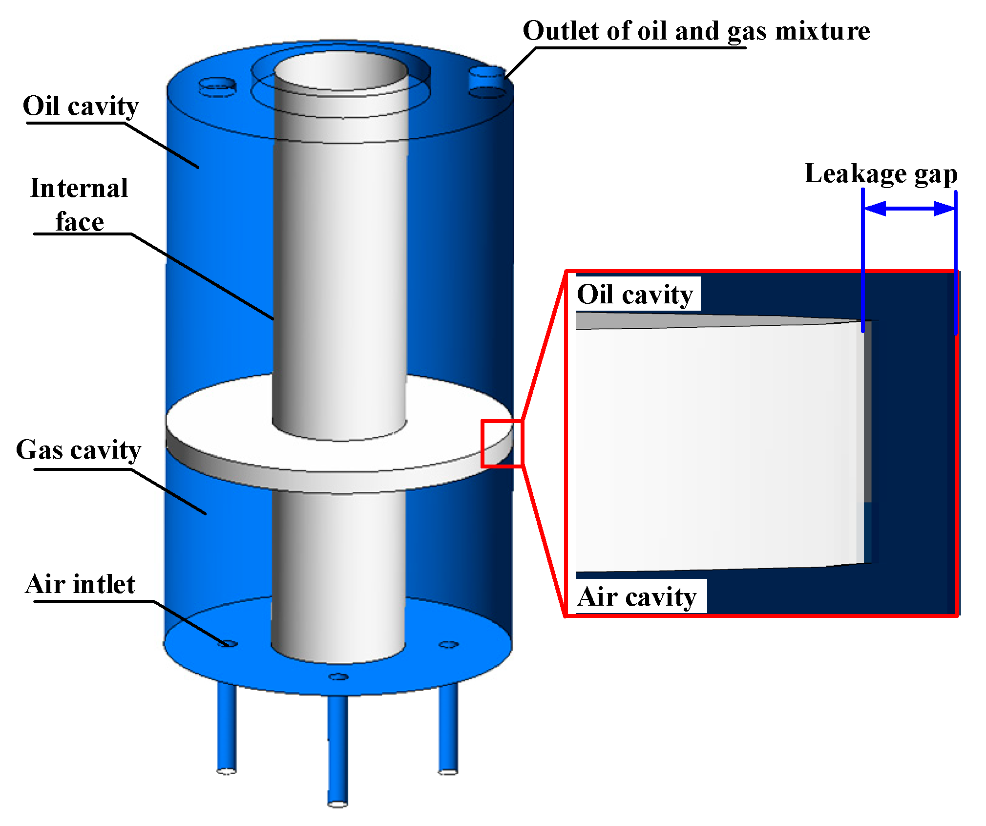
Figure 2 is the simulation model diagram of the oil–gas two-phase leakage flow experimental device with a small gap in the bearing cavity. Since the oil height of the numerical simulation can be given by the initial conditions; therefore, the model ignores the fuel tank part and retains the main parts such as the gas cavity, the oil cavity, and the sealing gap control disk. Figure 3 is the mesh division of the model, and the mesh is encrypted at the leakage gap. When the leakage gap is 0.2 mm, the number of meshes is selected to be 3.714 million after the independence verification. The setting of boundary conditions is shown in Table 2.

2.2.4. Comparison Validation

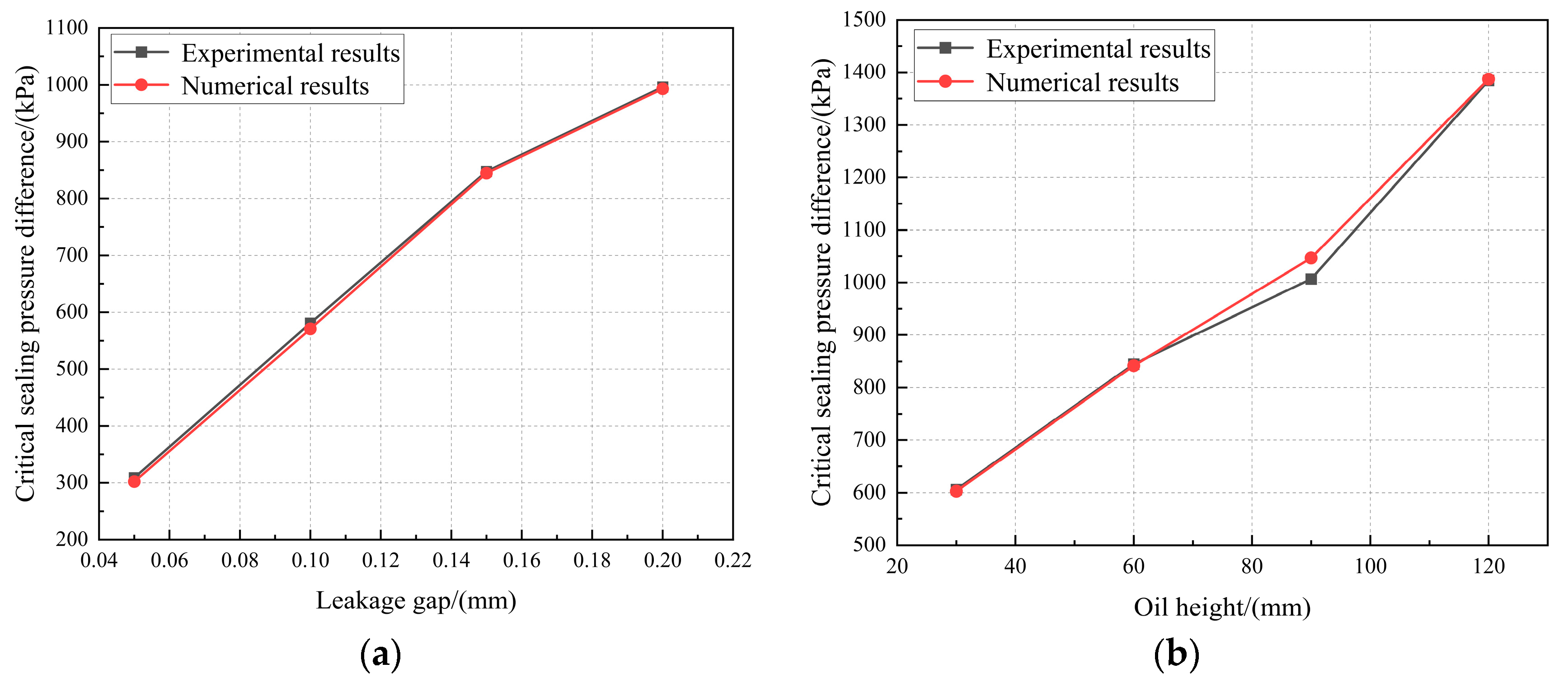
According to the experimental structure and working conditions of this section, numerical simulation work is carried out, the variation of critical sealing pressure difference with the size of leakage gap and the height of lubricating oil height is obtained, and the comparison between the simulation results and the experimental values is shown in Figure 4. As a whole, it can be seen that as the leakage gap decreases, the critical sealing pressure difference gradually decreases, and as the oil height increases, the required sealing pressure difference increases. The simulation results are consistent with the experimental results. The relative errors of the critical sealing oil pressure difference of different leakage gaps and oil height are all within 5%. The two-phase flow numerical simulation method used in this paper can meet the simulation and analysis of the oil–gas two-phase leakage flow characteristics of the bearing cavity sealing system.

3. Characteristic Analysis of the Bearing Cavity Sealing System

3.1. Geometric Model

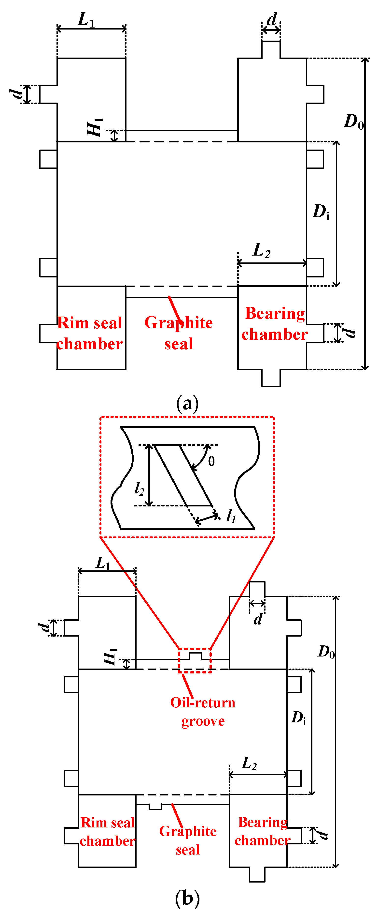
A two-dimensional structural diagram of the bearing cavity sealing system investigated in this study is presented in Figure 5. The sealing cavity, graphite sealing, and bearing cavity are interconnected consecutively. A sealing cavity with eight uniformly distributed air inlet ports is present on the left side. The central part involves a simplified uniform ring gap representing the graphite sealing gap. The bearing cavity equipped with eight evenly spaced oil supply ports is present on the right side. Additionally, an air vent structure is located above the bearing cavity, while an oil-return port structure can be found below the cavity.
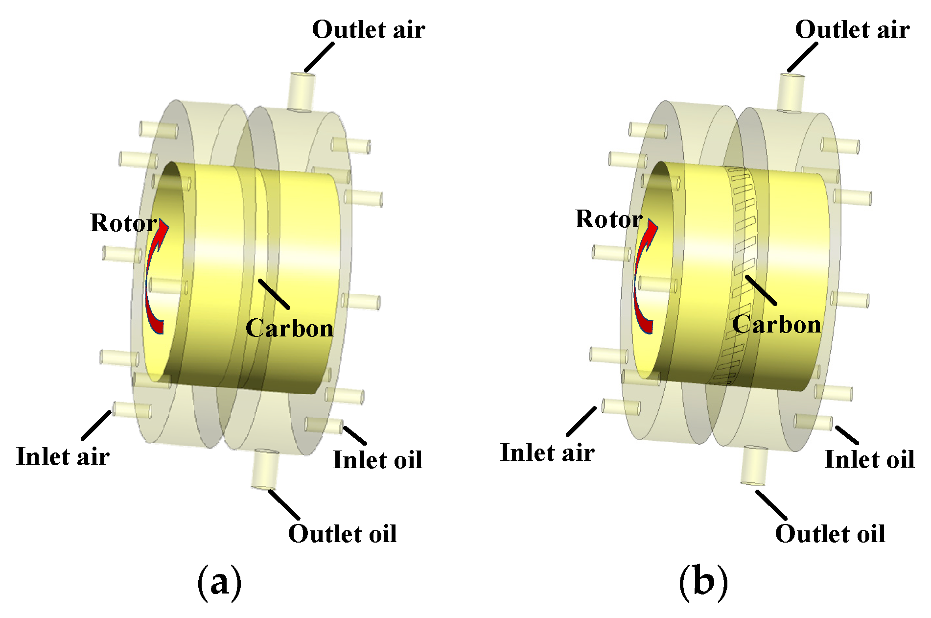
The numerical simulation employed a three-dimensional fluid domain model, as illustrated in Figure 6. The diameters of the sealing gas inlet, lubricating oil inlet, air vent, and oil-return port are all denoted as d. The width of the sealing cavity and bearing cavity are denoted as L1 and L2, respectively. The cavity possesses an inner diameter of Di and an outer diameter of D0. The dimensions of the groove, including its width (l1), length (l2), and angle (θ), are provided in Table 3.

3.2. Grid Division and Boundary Conditions

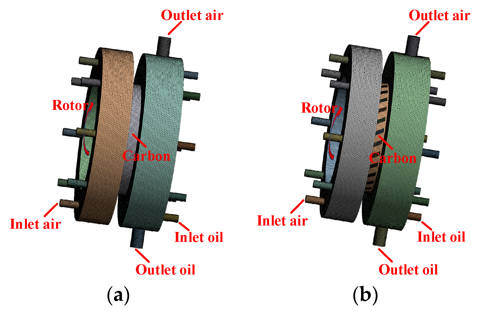
The geometric model of the bearing cavity sealing system was meshed using ANSYS 2020 R1 Meshing. The graphite seal area is a regular annular gap and needs to capture the oil film shear force with high precision; therefore, the structured grid is used, and the other areas are unstructured grids, as illustrated in Figure 7.
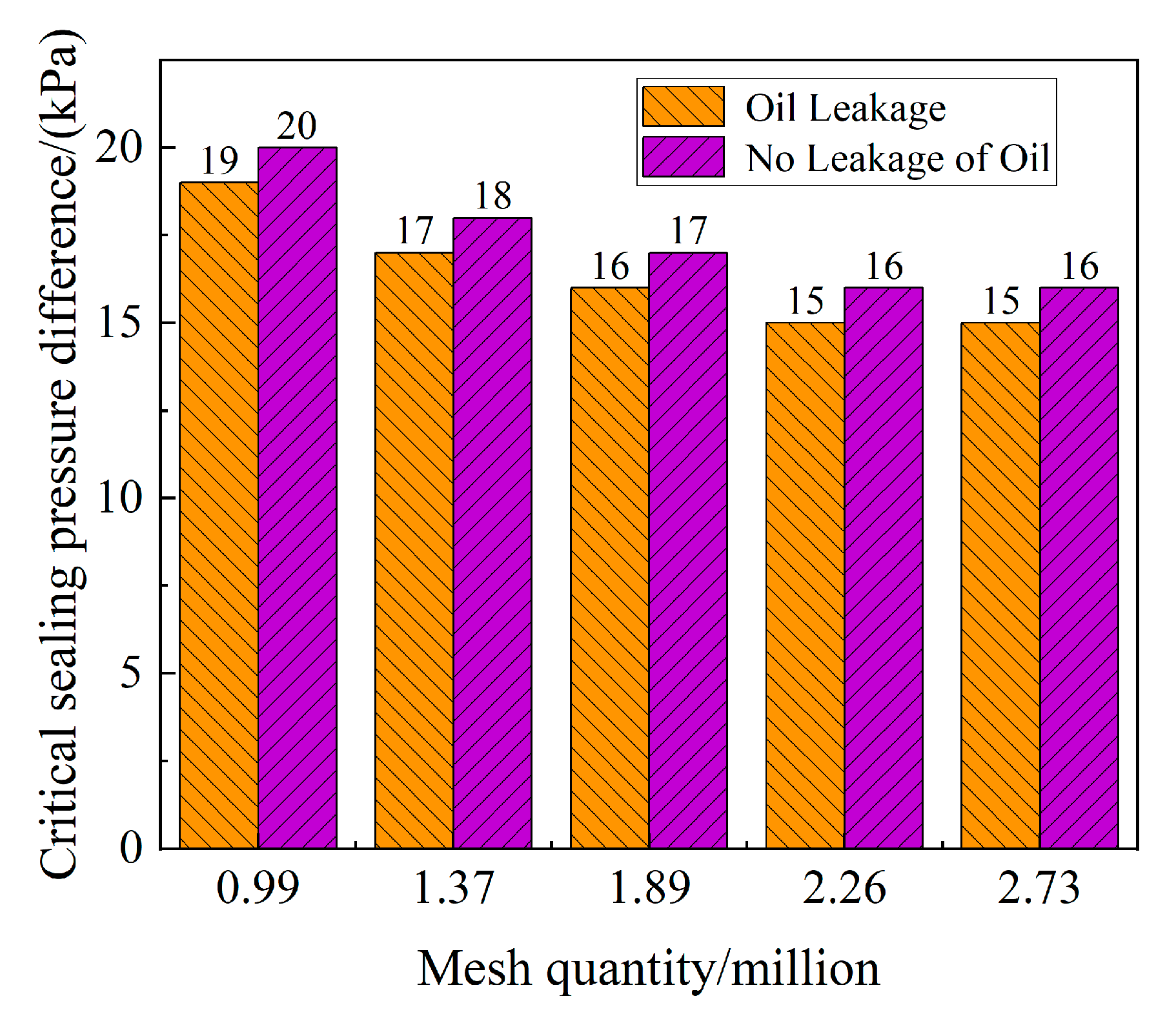
The graphite without oil-return groove bearing cavity sealing system was selected to carry out the grid independence verification. As shown in Figure 8, with the increase in the number of grids, the critical oil sealing pressure difference gradually stabilized after 2.26 million; therefore, the number of grids was determined to be 2.26 million.
The sealing gas inlet is set to the pressure inlet boundary, the oil inlet is the mass flow inlet boundary, the vent and the oil-return port are the pressure outlet boundaries, and the walls are non-slip walls. The specific boundary setting parameters are shown in Table 4.
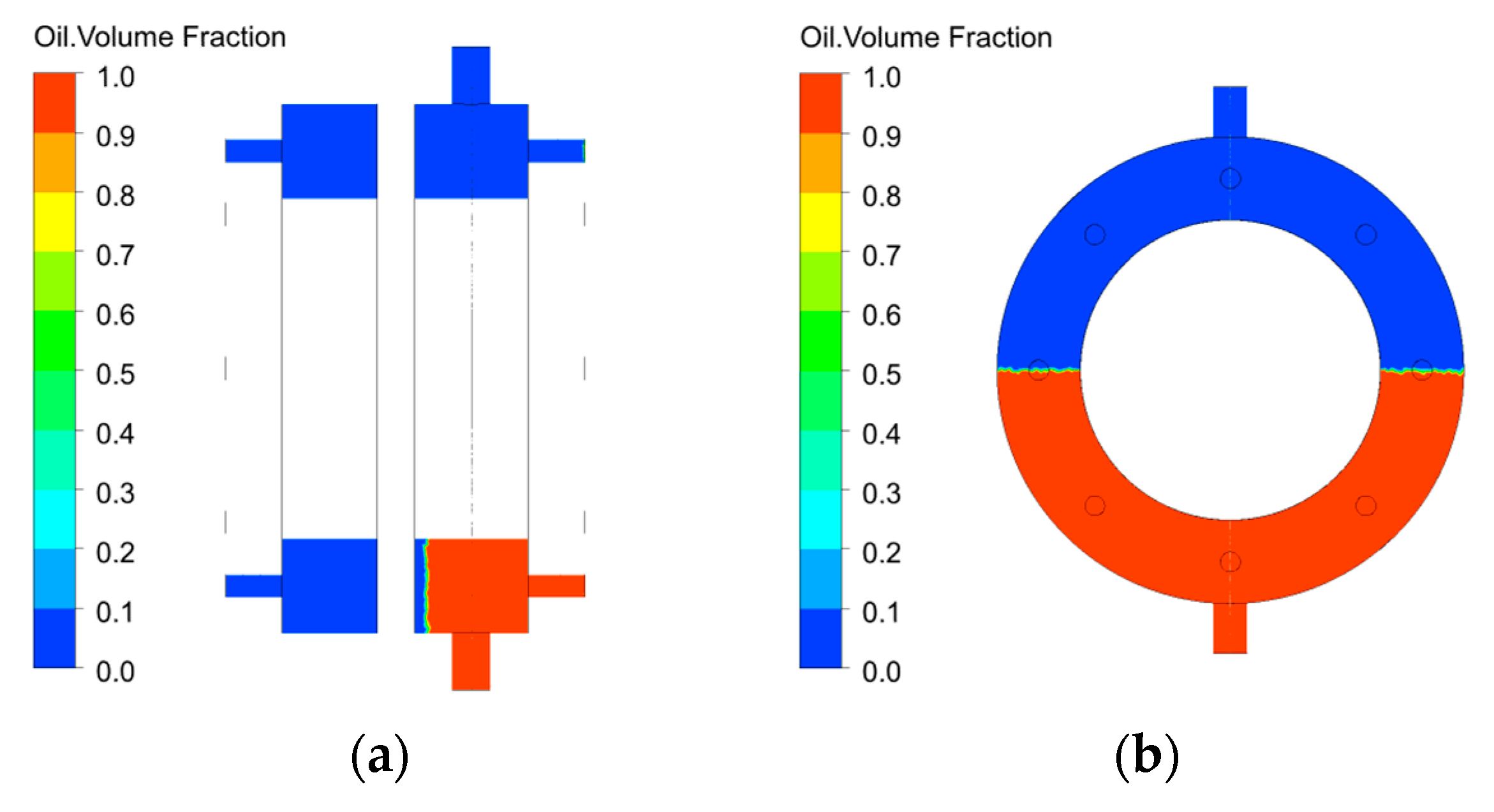
To judge the leakage state of the lubricating oil more quickly and accurately, it is assumed that there is lubricating oil under the bearing cavity in the initial time of the simulation. At the initial moment, there is no lubricating oil in the sealing cavity and the graphite sealing gap, and the initial oil height is shown in Figure 9.

3.3. Analysis of the Transient Characteristics of the Oil–Gas Two-Phase Flow Field in the Bearing Cavity

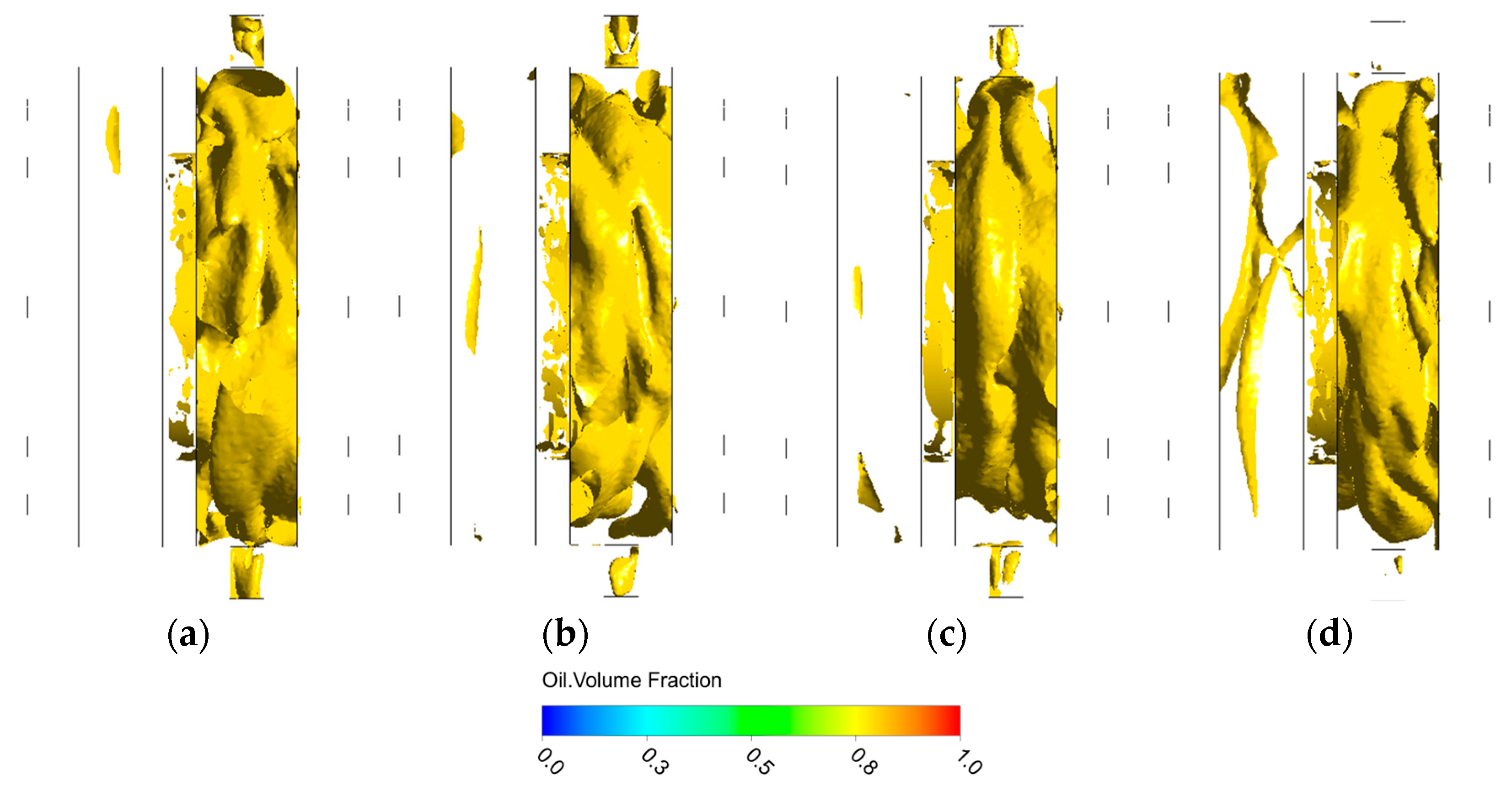
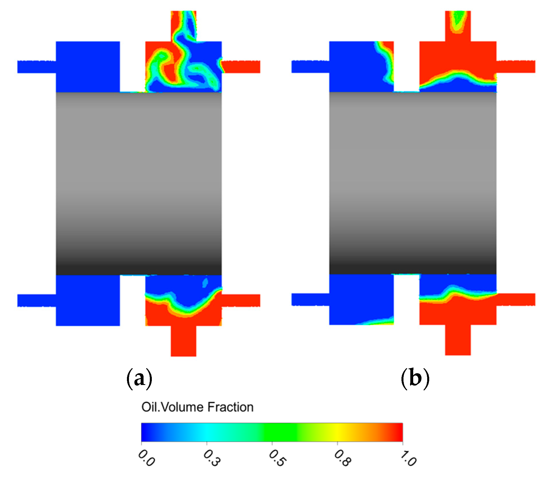
Figure 10 and Figure 11 show the oil volume fraction 0.8 contour map and the oil–gas two-phase distribution cloud map of the sealing cavity-graphite seal-bearing cavity sealing system under a pressure difference of 3 kPa, a rotate speed of 15,000 r/min, an oil flow rate of 0.1 kg/s, and an oil temperature of 60 °C, respectively.
From Figure 10, with the increase in time, the oil in the bearing cavity leaks through the graphite sealing gap into the sealing cavity, and the oil flow in the sealing cavity gradually increases. When t = 1.0 s, the oil flow in the sealing cavity is very small. With time, the lubricating oil in the bearing cavity gradually leaks into the sealing cavity through the sealing gap. At t = 3.0 s, the area with an oil volume fraction of 0.8 in the sealing cavity was significantly larger than that at t = 1.0 s. It is shown that the leakage of lubricating oil occurs in the bearing cavity system without oil-return groove. It can also be seen from Figure 11 that the area where the oil volume fraction is 1 at t = 4.5 s is significantly larger than that at t = 0.5 s. The sealing pressure difference under this condition is insufficient, which slightly hinders the flow of lubricating oil through the graphite sealing area in the bearing cavity, resulting in the leakage of lubricating oil into the sealing cavity. With time, the lubricating oil in the sealing cavity increases continuously.

3.4. Lubricating Oil Leakage Characteristics

3.4.1. Analysis of the Oil Leakage Characteristics of the Conventional Bearing Cavity Sealing System

  • Effect of sealing width on oil leakage characteristics
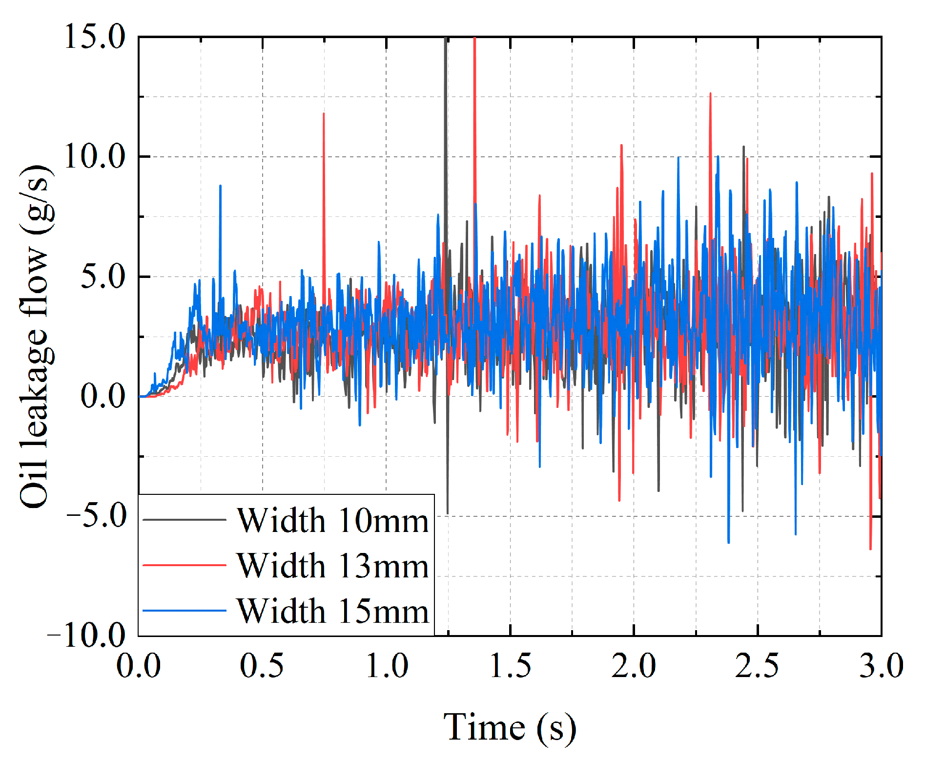
Figure 12 shows the variation in oil leakage with time according to different sealing widths of the conventional bearing cavity sealing system under the conditions of a pressure difference of 1 kPa, a rotate speed of 15,000 r/min, an oil flow rate of 0.1 kg/s, and an oil temperature of 60 °C.
The sealing width did not have a significant impact on oil leakage, as illustrated in Figure 12. Prior to 1.5 s, the oil leakage remained below 5 g/s. After 1.5 s, the leakage of oil increases, and the leakage reaches 10 g/s at local time. When the sealing width before 1.5 s is 10 mm, 13 mm, and 15 mm, respectively, the average leakage flow of lubricating oil is 2.45 g/s, 2.51 g/s, and 2.62 g/s, respectively. When the sealing width after 1.5 s is 10 mm, 13 mm, and 15 mm, respectively, the average leakage flow of lubricating oil is 2.79 g/s, 3.05 g/s, and 3.20 g/s, respectively. It can be seen that compared with the change in sealing width, the change in oil leakage is smaller. Given that the gap and flow area remain unchanged, along with consistent gas obstruction efficiency toward the oil within the bearing cavity, the variations in the sealing width exhibit limited sensitivity toward oil leakage.
2.
Effect of rotate speed on oil leakage characteristics
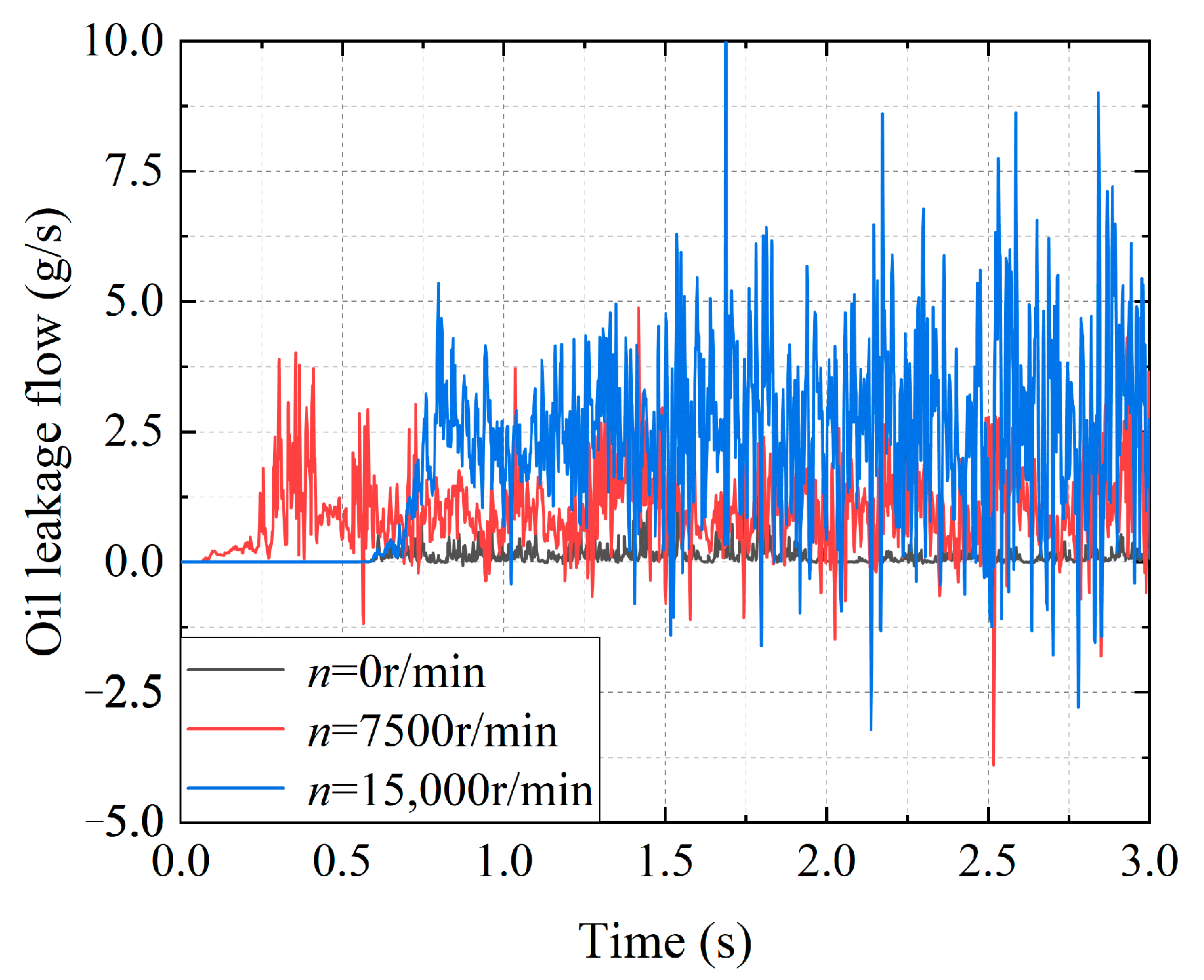
Figure 13 shows the pressure difference of 1 kPa, the oil flow rate of 0.1 kg/s, and the oil temperature of 60 °C, under different speed conditions. The oil leakage of the conventional bearing cavity sealing system changes with time.
From Figure 13, it can be seen that the higher the speed, the greater the oil leakage. When the rotate speed is 0 r/min, the leakage is close to 0 g/s. This is due to the low turbulence of the lubricating oil in the bearing cavity caused by the static rotation of the rotating shaft, and there is not enough kinetic energy to flow across the graphite sealing gap into the sealing cavity. When the rotate speed is 7500 r/min, the oil leakage is relatively obvious, and the oil leakage flow rate basically fluctuates in the range of 0~2.5 g/s. Although the rotate speed increases, the oil leakage in the bearing cavity is still small due to the low rotate speed. When the rotate speed is 15,000 r/min, the leakage flow of lubricating oil increases obviously. Most of the time, the leakage flow is in the range of 0~5 g/s, and the local leakage flow reaches 10 g/s. Due to the large rotation speed, the effect of air shear force on the lubricating oil increases, and more lubricating oil is thrown to the wall surface of the bearing cavity, which promotes the leakage of the lubricating oil along the graphite sealing gap into the sealing cavity.

3.4.2. Analysis of the Lubricating Oil Leakage Characteristics of the Graphite with Oil-Return Groove Bearing Cavity Sealing System

  • Impact of oil-return groove on the lubricating oil leakage characteristics
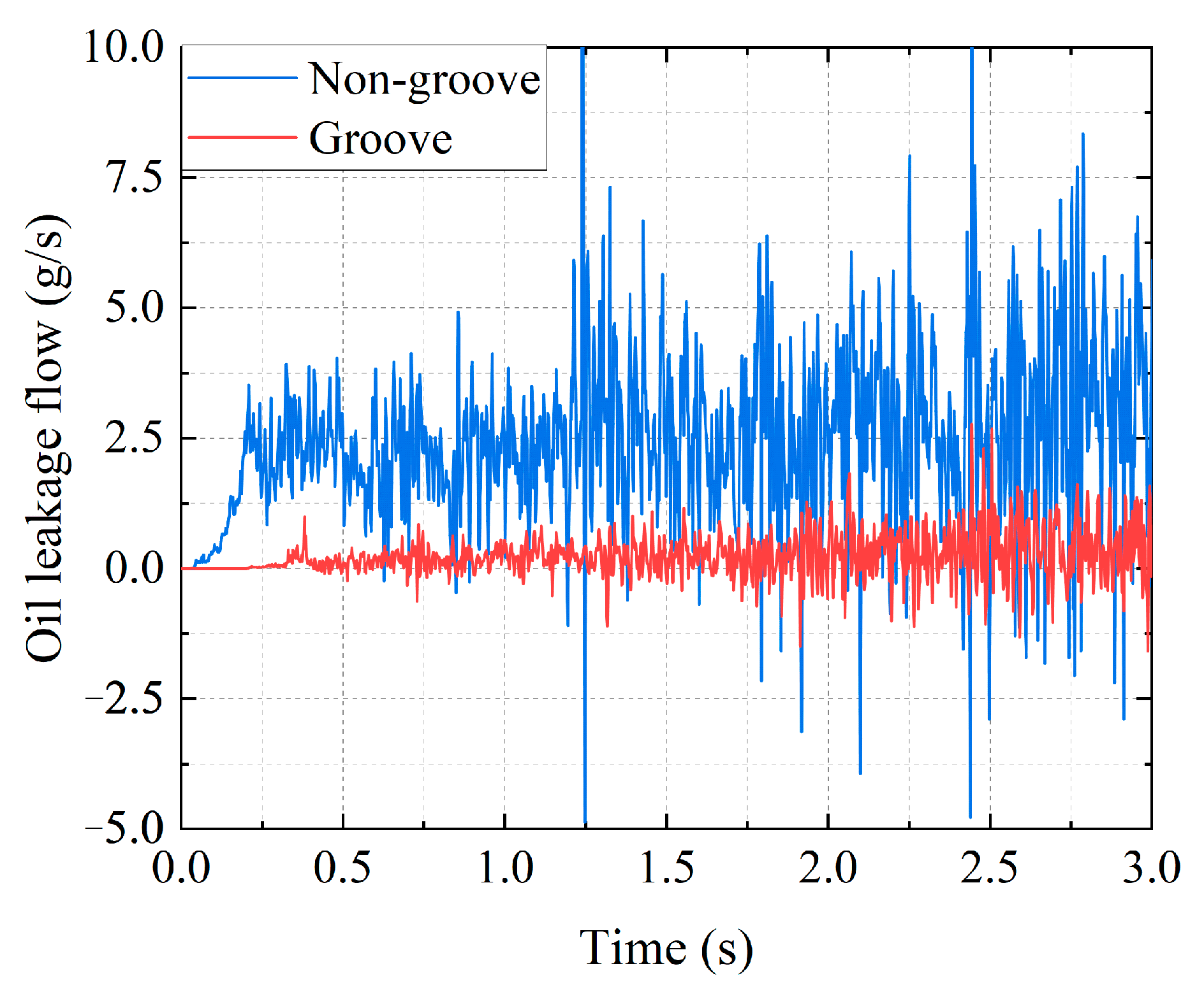
Figure 14 shows the variation in oil leakage with time in the sealing system of the bearing cavity with and without the oil-return groove graphite under the conditions of a pressure difference of 1 kPa, oil flow rate of 0.2 kg/s, oil temperature of 60 °C, and a rotate speed of 15,000 r/min.
As depicted in Figure 14, the oil leakage of the bearing cavity system without oil-return groove graphite is mainly in the range of 6.0 g/s, and it reaches 10 g/s at local time. The oil leakage of the bearing cavity sealing system with the oil-return groove graphite is obviously reduced, and it is within the range of 1.25 g/s. This may be attributed to the effect of the oil-return groove on the oil flowing through the graphite seal gap, resulting in the pumping action. A portion of the lubricating oil flowing into the graphite seal gap is pumped back into the bearing cavity, which reduces the leakage.
2.
Impact of oil-return groove length on the lubricating oil leakage characteristics
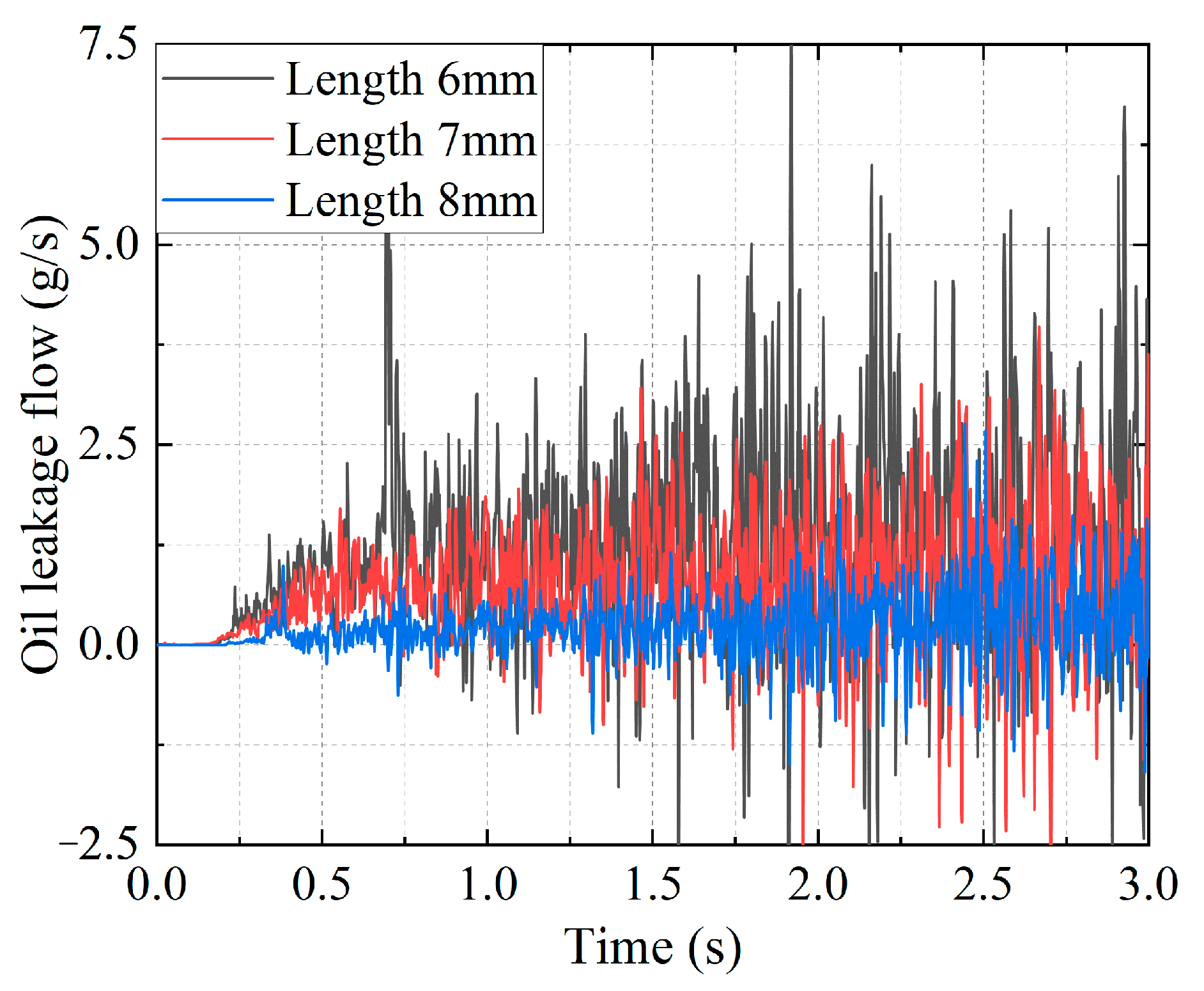
Figure 15 shows the impact of different oil-return groove lengths on the oil leakage of the bearing cavity sealing system under the conditions of a pressure difference of 1 kPa, oil flow rate of 0.2 kg/s, oil temperature of 60 °C, and oil-return groove of 15,000 r/min.
From Figure 15, it can be seen that with time, the leakage of lubricating oil increases from 0 g/s to stable. Before t = 0.25 s, there is less lubricating oil leaking from the bearing cavity into the sealing gap, and the pumping effect of the oil-return groove is obvious. After t = 0.25 s, the oil flow from the bearing cavity to the sealing gap first increases and then tends to be stable. At this time, the oil-return groove is not sufficient to completely pump the lubricating oil into the sealing gap back to the bearing cavity, resulting in leakage in the sealing cavity. When the length of the oil-return groove is 6 mm, the oil leakage is approximately 5 g/s, and the local time can reach 7.5 g/s. When the length of the oil-return tank is 7 mm, the oil leakage is approximately 2.5 g/s. When the length of the oil-return tank is 8 mm, the oil leakage is approximately 1.25 g/s. Thus, it can be concluded that with the increase in the length of the oil-return groove, the leakage of the lubricating oil decreases obviously. This is because the oil-return groove works on the oil in the sealing gap along the axial direction, so that the oil flows reversely. At the same time, the longer the oil-return groove is, the more work is conducted along the axial direction, so that more oil is pumped back to the bearing cavity.
3.
Impact of oil-return groove width on the lubricating oil leakage characteristics
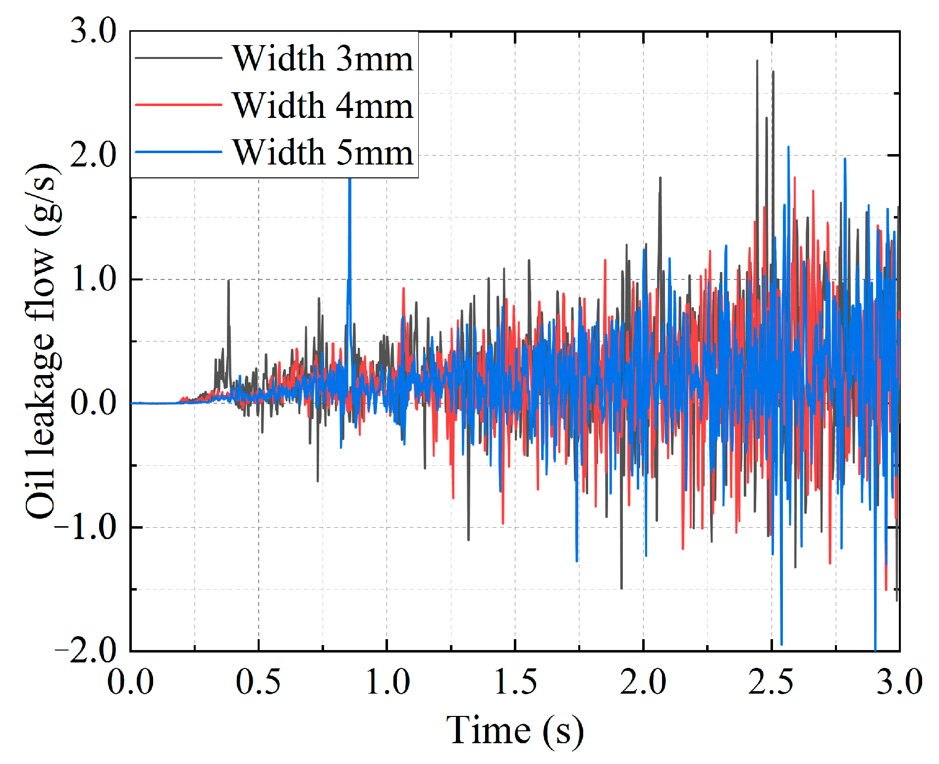
Figure 16 shows the impact of different oil-return groove widths on the oil leakage of the bearing cavity sealing system under the working conditions of a pressure difference of 1 kPa, oil flow rate of 0.2 kg/s, oil temperature of 60 °C, and rotate speed of 15,000 r/min.
From the figure, it can be seen that with time, the leakage of lubricating oil increases first and then tends to be stable from 0 g/s. When the width of the oil-return groove is 3, 4, and 5 mm, the oil leakage is approximately 1.5 g/s, and it may exceed 2 g/s in local time. It can be concluded that with the increase in the width of the oil-return groove, the change in oil leakage is not apparent. The oil-return groove widened, leading to a change in the length along the circumferential direction. Here, the axial length did not change, and thus, the sealing gap in the oil work change is not obvious; the oil leakage is basically same.
4.
Impact of the number of oil-return grooves on the leakage characteristics of the lubricating oil
Figure 17 shows the impact of different numbers of oil-return grooves on the oil leakage of the bearing cavity sealing system under the conditions of a pressure difference of 1 kPa, oil flow rate of 0.2 kg/s, oil temperature of 60 °C, and a rotate speed of 15,000 r/min.
It can be seen from Figure 17 that as the number of oil-return grooves increases, the leakage of lubricating oil decreases. This is because with the increase in the number of oil-return grooves, grooves perform more work to the oil flowing through the graphite sealing gap, thereby strengthening the pumping capacity. When the number of oil-return grooves is 10, the lubricating oil leaks before 0.25 s. This is because the number of oil-return grooves is small, and the pumping effect is weak, resulting in early leakage of lubricating oil compared with the other two structures. At the same time, most of the time, the leakage is less than 6 g/s, and the local time can reach 9 g/s. When the number of oil-return grooves is 20, the oil leakage is less than 4.5 g/s most of the time, and it can reach 7.5 g/s at local time. When the number of oil-return grooves is 30, the oil leakage most of the time is in the range of 1.5 g/s. The number of oil-return grooves increased from 20 to 30, and the pumping capacity was significantly enhanced, as a result, the lubricating oil leakage reduced.
5.
Impact of oil-return groove parameters on the mean value of oil leakage
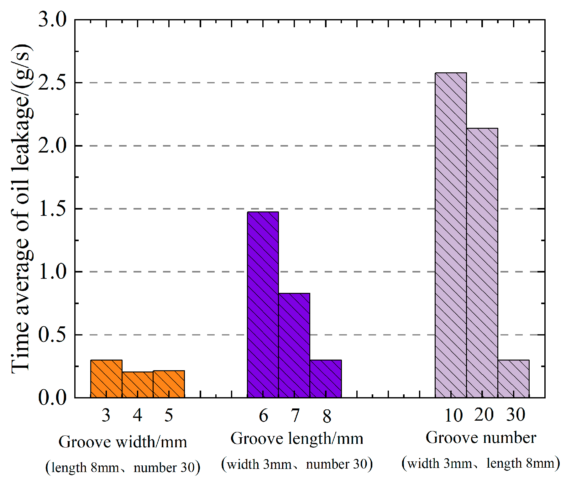
Figure 18 shows the impact of the oil-return tank parameters on the mean value of the oil leakage under the conditions of a pressure difference of 1 kPa, oil flow rate of 0.2 kg/s, oil temperature of 60 °C, and an oil-return tank parameter of 15,000 r/min.
The figure shows that as the width of the oil-return tank increases, the average value of the oil leakage decreases slightly, and the range of variation is very small. With the increase in the length of the oil-return tank, the time-average value of the oil leakage decreases approximately linearly. As the number of oil-return grooves increases, the average value of oil leakage decreases. The decrease in the range of the average value of oil leakage from 10 to 20 oil-return grooves is less than that from 20 to 30 oil-return grooves. It can be concluded that the width of the oil-return tank is not sensitive to the mean value of the oil leakage, and the mean value decreases when the length and number of the oil-return tank increase the oil leakage.

3.5. Critical Sealing Oil Characteristics

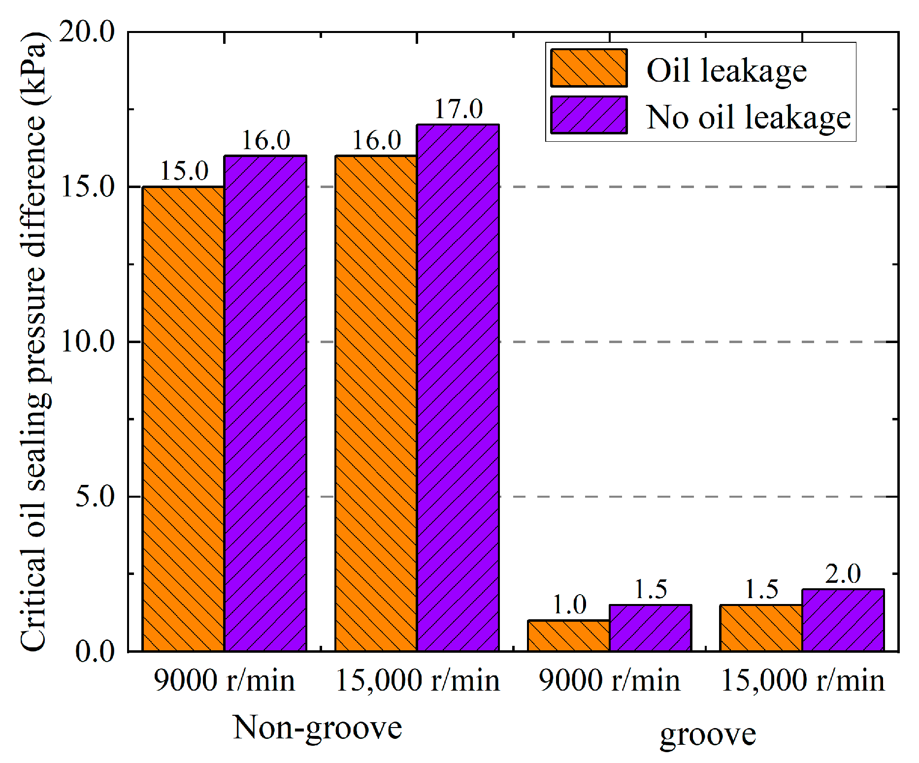
The variation in the critical sealing pressure difference with the rotate speed is depicted in Figure 19, considering an oil flow rate of 0.2 kg/s and an oil temperature of 60 °C.
From the figure, it can be seen that the pressure difference of the conventional bearing cavity sealing system without oil leakage at 15,000 r/min is higher than that at 9000 r/min. At a rotate speed of 9000 r/min, oil leaks into the sealing cavity with a pressure difference of 15 kPa, while no oil leakage occurs with a pressure difference of 16 kPa; the critical sealing pressure difference range can be determined between 15 and 16 kPa. However, at a rotate speed of 15,000 r/min, oil leaks into the sealing cavity with a pressure difference of 16 kPa, whereas no leakage occurs with a pressure difference of 17 kPa. Thus, the critical sealing pressure difference range can be established between 16 and 17 kPa. This is due to the increase in rotate speed, which promotes the leakage of lubricating oil across the graphite sealing gap into the sealing cavity, resulting in an increase in the critical sealing pressure difference. The critical sealing pressure difference of the graphite with oil-return groove bearing cavity sealing system is in the range of 1–1.5 kPa at a speed of 9000 r/min. When the speed is 15,000 r/min, the critical sealing pressure is in the range of 1.5–2.0 kPa. Compared with the conventional bearing cavity sealing system, the critical oil sealing pressure difference of the graphite with oil-return groove bearing cavity sealing system is reduced by more than 90%. This is because the oil-return groove works on the oil in the graphite sealing gap, and thus, some part of the oil is reversely pumped back into the bearing cavity, thereby reducing the oil flowing into the sealing cavity, and a smaller pressure difference is required to suppress the oil leakage.
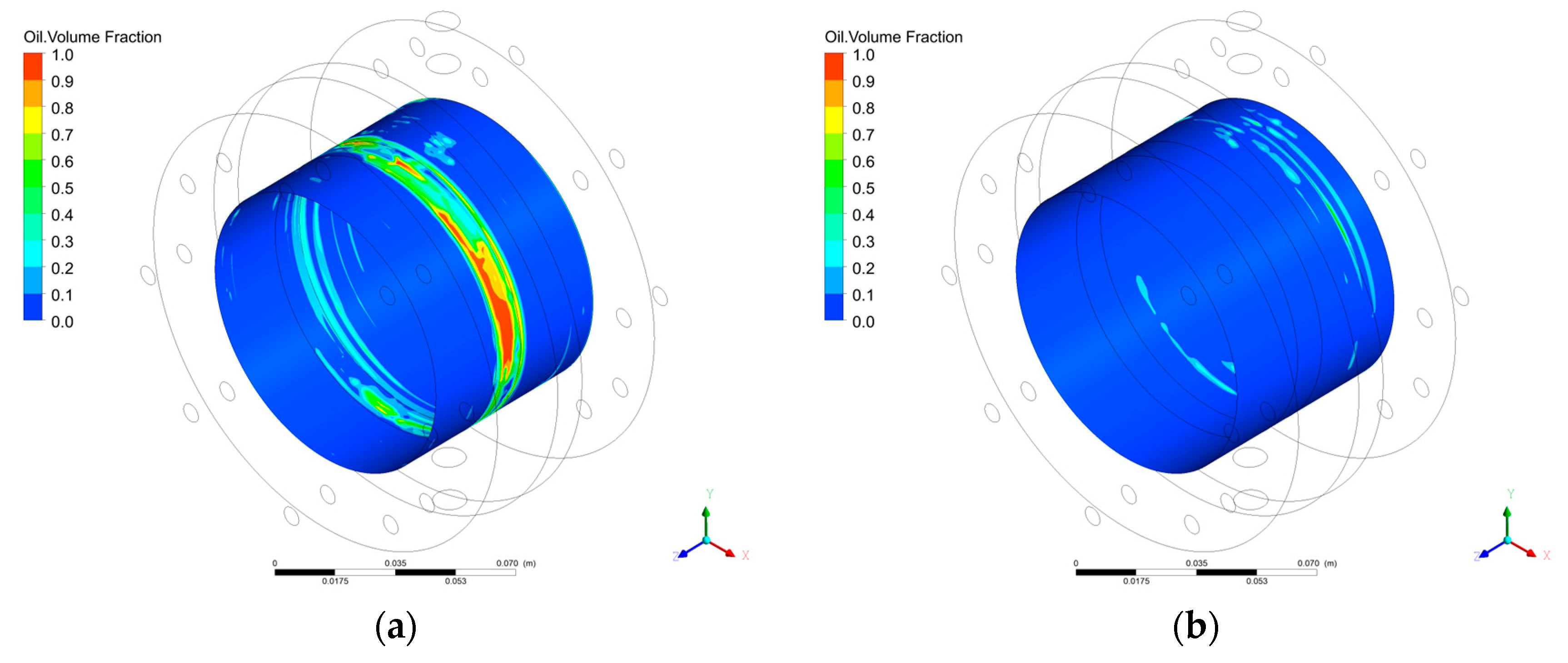
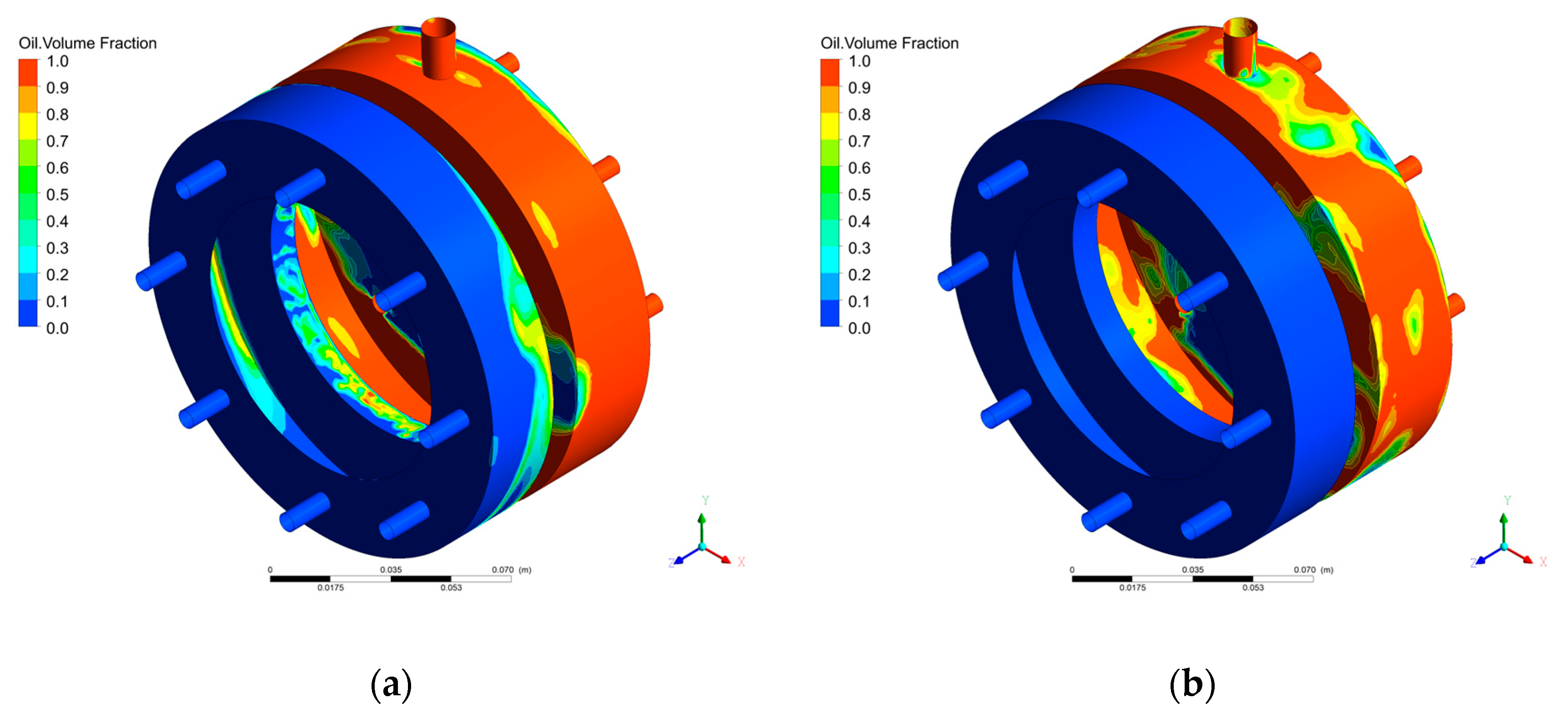
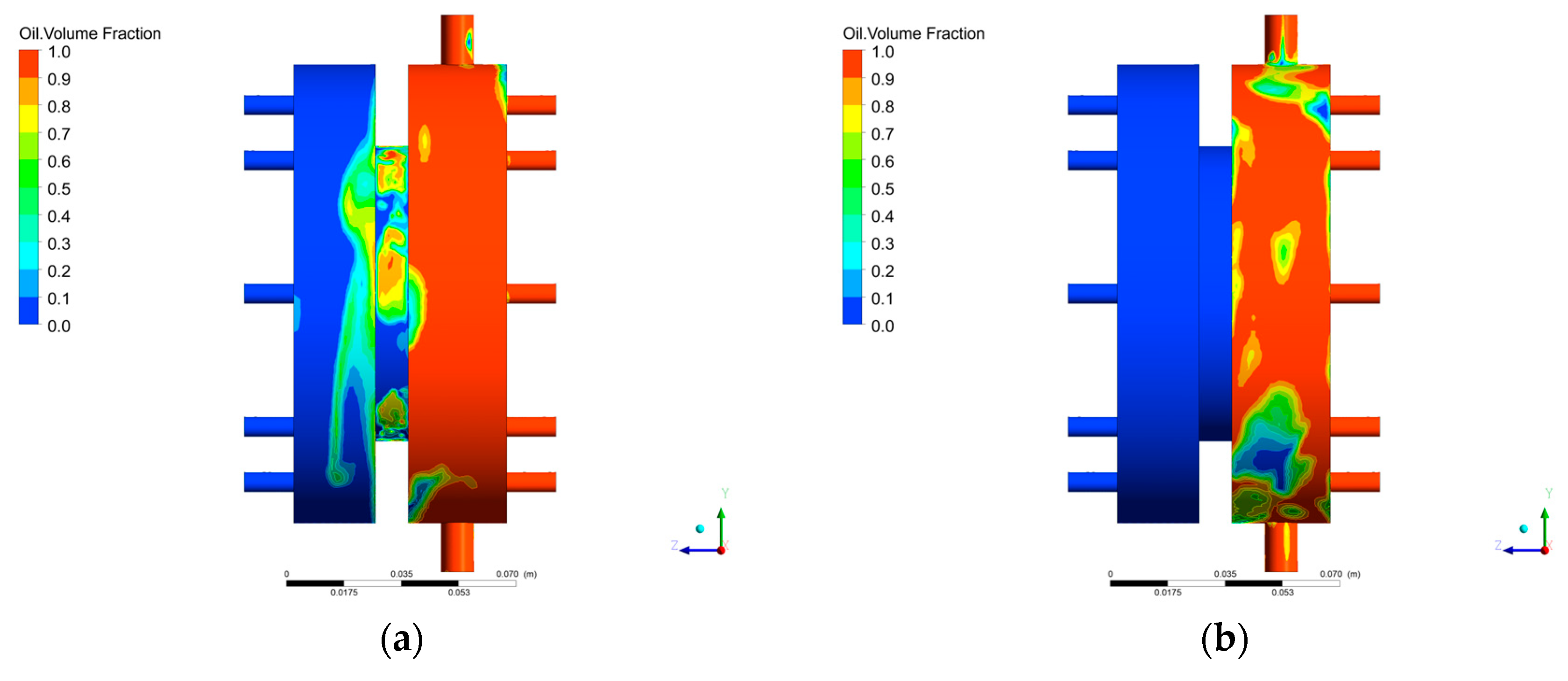
In order to further determine the critical sealing oil pressure difference of the conventional bearing cavity sealing system at 9000 r/min, Figure 20 and Figure 21, respectively, show the effects of different sealing pressure differences on the oil–gas distribution on the rotor surface and stator surface of the bearing cavity sealing system under the working conditions of 9000 r/min speed, 0.2 kg/s oil flow rate, and 60 °C oil temperature. Figure 22 shows the distribution of lubricating oil in the graphite seal gap under this working condition.
It can be seen from the figure that when the sealing pressure difference is 15 kPa, there is a small amount of lubricating oil on the rotor surface of the sealing cavity, and there is more lubricating oil on the stator surface. The graphite sealing gap is filled with more lubricating oil, indicating that the lubricating oil in the bearing cavity leaks into the sealing cavity through the graphite sealing gap. When the pressure difference is 16 kPa, there is no obvious lubricating oil on the rotor surface and stator surface of the sealing cavity, and there is no lubricating oil in the graphite sealing gap, indicating that the gas in the sealing cavity flows into the bearing cavity through the sealing gap. The pressure of the sealing gas meets the sealing requirements, and the lubricating oil in the bearing cavity does not leak. By judging, the critical sealing oil pressure difference is in the range of 15 kPa~16 kPa under this working condition.
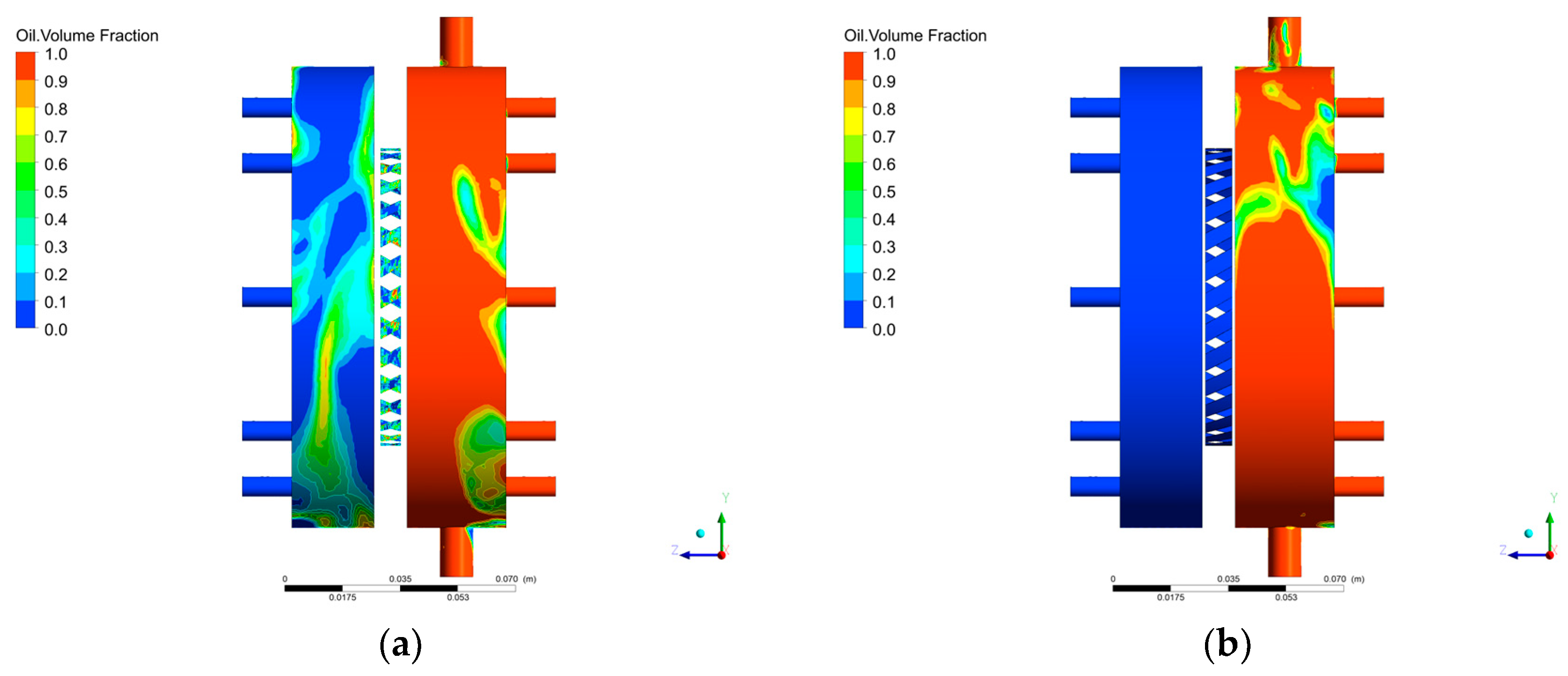
In order to further determine the critical sealing pressure difference of the graphite with oil-return groove bearing cavity sealing system at 15,000 r/min, Figure 23 and Figure 24, respectively, show the effects of different sealing pressure differences on the oil–gas distribution on the rotor surface and stator surface of the bearing cavity sealing system under the working conditions of 15,000 r/min speed, 0.2 kg/s oil flow rate, and 60 °C oil temperature. Figure 25 shows the distribution of lubricating oil in the graphite sealing gap under this working condition.
It can be seen from the diagram that when the pressure difference is 1.5 kPa, there is no obvious accumulation of lubricating oil on the rotor surface of the sealing cavity, there is a small amount of lubricating oil on the stator surface, and the graphite sealing gap is filled with more lubricating oil, indicating that the lubricating oil in the bearing cavity leaks under this working condition. When the pressure difference is 2.0 kPa, there is no lubricating oil in the sealing cavity and the graphite sealing gap, indicating that there is no leakage of lubricating oil. According to the judgment, the critical sealing oil pressure difference is in the range of 1.5 kPa~2.0 kPa under this working condition.

4. Conclusions

In this study, the numerical simulation method of the oil–gas two-phase flow and leakage characteristics of the bearing cavity sealing system is established. Furthermore, the reliability of the method is verified through the experiment of the oil leakage characteristics through a small gap. The simulation analysis was conducted for the conventional bearing cavity sealing system and the graphite with oil-return groove bearing cavity sealing system. The two-phase flow characteristics, leakage characteristics, and critical oil sealing characteristics of the two structures were obtained. The following conclusions were obtained:
  • With time, the lubricating oil in the sealing cavity gradually increased.
  • For the conventional bearing cavity sealing system, the change in sealing width has no obvious effect on the oil leakage, and the oil leakage is approximately 10 g/s. The oil leakage increases with speed. At 0 r/min, the oil leakage is less than 0.5 g/s, and at 15,000 r/min, the oil leakage is less than 10 g/s.
  • Under the working condition of 1 kPa, the oil leakage of the graphite with oil-return groove structure reduced. The oil leakage decreases by 87.6% at 1 s, 82.3% at 2 s, and 98.1% at 3 s. Furthermore, the length and number of oil-return groove increased, and the leakage of lubricating oil decreased. The effect of change in the width of the oil-return groove on oil leakage is negligible.
  • The critical sealing pressure difference of the conventional bearing cavity sealing system is 15~16 kPa when the rotate speed is 9000 r/min, and the critical sealing pressure difference is 16~17 kPa when the rotate speed is 15,000 r/min. The critical sealing pressure difference of the bearing cavity sealing system with oil-return groove graphite is 1~1.5 kPa when the rotate speed is 9000 r/min, and the critical sealing pressure difference is 1.5~2.0 kPa when the rotate speed is 15,000 r/min. Under the same working conditions, the critical sealing oil pressure difference of the graphite with oil-return groove bearing cavity sealing system is more than 90% lower than that of the conventional bearing cavity sealing system.
For the conventional bearing cavity sealing system, the improved method of graphite with oil-return groove can enhance the sealing performance of the bearing cavity system and reduce the leakage of lubricating oil. Increasing the length and number of oil-return grooves can more effectively reduce the oil leakage of the bearing cavity.

Author Contributions

Writing—original draft preparation, R.W.; writing—review and editing, G.R.; supervision, W.X.; project administration, D.S.; funding acquisition, Y.L. All authors have read and agreed to the published version of the manuscript.

Funding

This research received no external funding.

Data Availability Statement

Data is contained within the article.

Acknowledgments

The authors are grateful to the reviewers for their careful and detailed comments.

Conflicts of Interest

The authors declare no conflicts of interest.

References

  1. Attia, H.A.; Chandra, B.; Toomer, C. Computational and experimental representation of simplified gas turbine bearing chamber geometries. Int. J. Thermofluids 2025, 26, 101097. [Google Scholar] [CrossRef]
  2. Xu, Y.; Hu, J.; Lyu, Y.; Liu, Z. Experimental study of shear-driven film flows in aeroengine bearing chamber. J. Braz. Soc. Mech. Sci. Eng. 2025, 47, 171. [Google Scholar] [CrossRef]
  3. Farrall, M.; Hibberd, S.; Simmons, K. The Effect of Initial Injection Conditions on the Oil Droplet Motion in a Simplified Bearing Chamber. ASME J. Eng. Gas Turbines Power 2008, 130, 012501. [Google Scholar] [CrossRef]
  4. Farrall, M.; Simmons, K.; Hibberd, S.; Gorse, P. A Numerical Model for Oil Film Flow in an Aeroengine Bearing Chamber and Comparison to Experimental Data. ASME J. Eng. Gas Turbines Power 2006, 128, 111–117. [Google Scholar] [CrossRef]
  5. Chen, B.; Chen, G.D.; Sun, H.C.; Zhang, Y.H. Effect of oil droplet deformation on its deposited characteristics in an aeroengine bearing chamber. Proc. Inst. Mech. Eng. Part G J. Aerosp. Eng. 2014, 228, 206–218. [Google Scholar] [CrossRef]
  6. Li, Y.; Li, R.; Tian, A.; Xu, X.; Zhang, H. Research on leakage characteristics of labyrinth seal based on air-oil two-phase flow. Multidiscip. Model. Mater. Struct. 2025, 21, 270–290. [Google Scholar] [CrossRef]
  7. Aissa, D.O.H.; Lysytsia, O.; Mykhailenko, T.; Petukhov, I. CFD modeling of multiphase flows in the gas turbine engines oil cavities. East.-Eur. J. Enterp. Technol. 2020, 2, 104. [Google Scholar] [CrossRef]
  8. Ren, G.; Li, Y.; Zhao, H.; Yan, Y.; Xu, W.; Sun, D. Research on Oil–Gas Two-Phase Flow Characteristics and Improvement of Aero-Engine Bearing Chamber. Lubricants 2023, 11, 360. [Google Scholar] [CrossRef]
  9. Li, S.; Li, C.; Wang, W. Simulation of Unsteady Flows of Oil/Gas in the Ventless Bearing Chamber of an Aero-Engine. Aerospace 2022, 9, 211. [Google Scholar] [CrossRef]
  10. Farrall, M.; Simmons, K.; Hibberd, S.; Gorse, P. A numerical model for oil film flow in an aero-engine bearing chamber and comparison with experimental data. In Proceedings of the ASME Turbo Expo: Power for Land, Sea, and Air, Vienna, Austria, 14–17 June 2004; pp. 409–417. [Google Scholar] [CrossRef]
  11. Wen, B.; Li, Y.; Li, Y.; Wang, M.; Zhai, J. Influence and Optimization of Nozzle Position on Lubricant Distribution in an Angular Contact Ball Bearing Cavity. Lubricants 2024, 12, 419. [Google Scholar] [CrossRef]
  12. Li, J.; Qu, B.; Qian, Y.; Liu, Z.; Li, Z. Identification of Oil and Gas Two-Phase Flow Patterns in Aero-Engine Bearing Chambers Based on Kriging Method. Int. J. Comput. Fluid Dyn. 2023, 37, 316–332. [Google Scholar] [CrossRef]
  13. Lu, P.; Fang, L.; Wang, X.; Wang, Q.; Zhang, J. Influences of the Geometry of the Scavenge Pipe on the Air-Oil Two-Phase Flow and Heat Transfer in an Aero-Engine Bearing Chamber. ACS Omega 2019, 4, 15226–15233. [Google Scholar] [CrossRef] [PubMed]
  14. Adeniyi, A.A.; Morvan, H.P.; Simmons, K.A. A Transient CFD Simulation of the Flow in a Test Rig of an Aeroengine Bearing Chamber. In Volume 5C: Heat Transfer, Proceedings of the ASME Turbo Expo 2014: Turbine Technical Conference and Exposition, Düsseldorf, Germany, 16–20 June 2014; ASME: New York, NY, USA, 2014. [Google Scholar] [CrossRef]
  15. Arghir, M.; Mariot, A. Theoretical analysis of the static characteristics of the carbon segmented seal. J. Tribol. Trans. ASME 2017, 139, 062202. [Google Scholar] [CrossRef]
  16. Tam, L.T.; Przekwas, A.J.; Muszynska, A.; Hendricks, R.C.; Braun, M.J.; Mullen, R.L. Numerical and analytical study of fluid dynamic forces in seals and bearings. J. Vib. Acoust. 1988, 110, 315–325. [Google Scholar] [CrossRef]
  17. Duan, W.; Chu, F.; Kim, C.H.; Lee, Y.B. A bulk-flow analysis of static and dynamic characteristics of floating ring seals. Tribol. Int. 2007, 40, 470–478. [Google Scholar] [CrossRef]
  18. Zhou, X.; Chen, C.; Li, J.; Wu, Y. Study on Radial Clearance Sealing Performance of Graphite Ring. J. Press. Vessel. Technol. 2021, 143, 031703. [Google Scholar] [CrossRef]
  19. Gao, B.C.; Meng, X.K.; Shen, M.X.; Peng, X.D. Transient thermal-mechanical coupling behavior analysis of mechanical seals during start-up operation. IOP Conf. Ser. Mater. Sci. Eng. 2016, 129, 012025. [Google Scholar] [CrossRef]
  20. Xue, B.; Wei, C.; Hu, J.B. Study of separation characteristics of micro-groove rotary seal considering different cavitation boundary conditions. Tribol. Lett. 2017, 65, 119. [Google Scholar] [CrossRef]
  21. Li, Z.; Li, Y.; Cao, H.; Hao, M.; Liu, F.; Meng, D. Investigation of cavitation evolution and hydrodynamic performances of oil film seal with spiral groove. Tribol. Int. 2021, 157, 106915. [Google Scholar] [CrossRef]
  22. Ren, G.Z.; Li, Y.P.; Zhao, H.; Xu, W.; Sun, D.; Yan, Y. Research on leakage flow characteristics of bearing chamber sealing system based on oil-gas two-phase flow. J. Aerosp. Power 2024, 40, 20230471. [Google Scholar] [CrossRef]
  23. Guo, J.; Zhao, H.; Wang, P.; Sun, D.; Wang, S. Numerical and Experimental Study on Oil-air Two-phase, Eakage Flow Characteristics Based on Air-bleeding Oil-sealing Mode in Seal Clearance of Bearing Cavity. J. Mech. Eng. 2024, 60, 214–225. [Google Scholar] [CrossRef]
  24. Ren, G.; Tang, H.; Yan, Y.; Xu, W.; Sun, D. Study on Oil Flow and Leakage Characteristics of Bearing Chamber Graphite Sealing Structure Considering Cavitation Effect. J. Aerosp. Power 2025. [Google Scholar] [CrossRef]
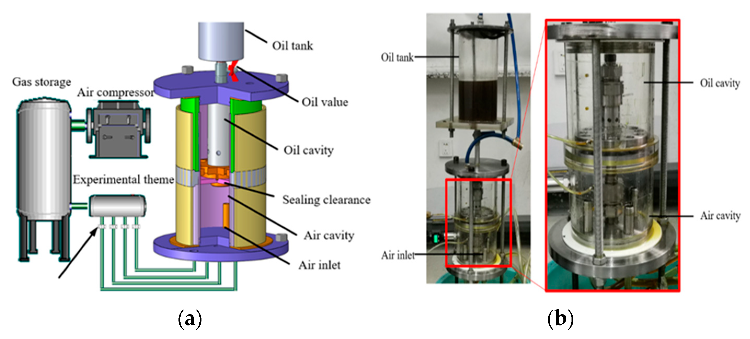
Figure 1. Experimental facility: (a) Diagrammatic drawing; (b) Object pictures.
Lubricants 13 00384 g001
Figure 2. Experimental device model.
Lubricants 13 00384 g002
Figure 3. Experimental device grid.
Lubricants 13 00384 g003
Figure 4. Accuracy verification: (a) Effect of leakage gap on critical sealing pressure difference; (b) Effect of oil height on critical sealing pressure difference.
Lubricants 13 00384 g004
Figure 5. Two-dimensional schematic diagram of the bearing cavity sealing system: (a) Graphite without oil-return groove; (b) Graphite with oil-return groove.
Lubricants 13 00384 g005
Figure 6. Geometric model of the bearing cavity sealing system: (a) Graphite without oil-return groove structure; (b) Graphite with oil-return groove structure.
Lubricants 13 00384 g006
Figure 7. Meshing of the bearing cavity sealing system: (a) Graphite without oil-return groove structure; (b) Graphite with oil-return groove structure.
Lubricants 13 00384 g007
Figure 8. The influence of the number of grids on the critical sealing pressure difference.
Lubricants 13 00384 g008
Figure 9. Initial oil height: (a) Left view; (b) Main view.
Lubricants 13 00384 g009
Figure 10. Isosurface diagram of lubricating oil volume fraction of 0.8 (Δp = 3 kPa and n = 15,000 r/min): (a) 1.0 s; (b) 1.5 s; (c) 2.0 s; (d) 3.0 s.
Lubricants 13 00384 g010
Figure 11. Effect of time on oil–gas distribution (Δp = 3 kPa and n = 15,000 r/min): (a) 0.5 s; (b) 4.5 s.
Lubricants 13 00384 g011
Figure 12. Effect of sealing width on oil leakage (Δp = 1 kPa and n = 15,000 r/min).
Lubricants 13 00384 g012
Figure 13. Effect of rotation on oil leakage (Δp = 1 kPa).
Lubricants 13 00384 g013
Figure 14. Effect of groove on oil leakage (Δp = 1 kPa and n = 15,000 r/min).
Lubricants 13 00384 g014
Figure 15. Effect of length on oil leakage (Δp = 1 kPa and n = 15,000 r/min).
Lubricants 13 00384 g015
Figure 16. Effect of width on oil leakage (Δp = 1 kPa and n = 15,000 r/min).
Lubricants 13 00384 g016
Figure 17. The effect of number on oil leakage (Δp = 1 kPa and n = 15,000 r/min).
Lubricants 13 00384 g017
Figure 18. Time-average value of oil leakage varies with the parameters of the oil-return groove (Δp = 1 kPa and n = 15,000 r/min).
Lubricants 13 00384 g018
Figure 19. Effect of rotate speed on critical oil sealing pressure difference.
Lubricants 13 00384 g019
Figure 20. The oil–gas two-phase distribution on the rotor surface of the conventional bearing cavity sealing system at 9000 r/min: (a) 15 kPa; (b) 16 kPa.
Lubricants 13 00384 g020
Figure 21. The oil–gas two-phase distribution on the stator surface of the conventional bearing cavity sealing system at 9000 r/min: (a) 15 kPa; (b) 16 kPa.
Lubricants 13 00384 g021
Figure 22. The oil–gas two-phase distribution on the graphite sealing gap of the conventional bearing cavity sealing system at 9000 r/min: (a) 15 kPa; (b) 16 kPa.
Lubricants 13 00384 g022
Figure 23. The oil–gas two-phase distribution on the rotor surface of the graphite with oil-return groove bearing cavity sealing system at 15,000 r/min: (a) 1.5 kPa; (b) 2.0 kPa.
Lubricants 13 00384 g023
Figure 24. The oil–gas two-phase distribution on the stator surface of the graphite with oil-return groove bearing cavity sealing system at 15,000 r/min: (a) 1.5 kPa; (b) 2.0 kPa.
Lubricants 13 00384 g024
Figure 25. The oil–gas two-phase distribution on the graphite sealing gap of the graphite with oil-return groove bearing cavity sealing system at 15,000 r/min: (a) 1.5 kPa; (b) 2.0 kPa.
Lubricants 13 00384 g025
Table 1. The main structural parameters of the experimental device.
ParameterValue
Oil cavity, gas cavity diameter/mm155.00
Leakage gap size/mm0.05~0.20
Sealing gap length/mm10.00
Oil cavity height/mm155.00
Gas cavity height/mm90.00
Inlet hole diameter/mm8.00
Table 2. Boundary conditions.
ParameterValue
Inlet total pressure/Pa200~2000
Outlet static pressure/Pa0
Reference pressure/atm1
Gravity acceleration/(m/s2)9.8
Oil height/mm30~120
Oil temperature/°C25
Two-phase flow modelMixture
Turbulence modelSST
Table 3. Structural parameters.
ParameterValue
Inside diameter Di/mm78.6
Outside diameter D0/mm98
Sealing gap H1/μm50
Width of sealing cavity L1/mm30
Width of bearing cavity L2/mm30
Cavity height e/mm15
Sealing length L3/mm10
Width of groove l1/mm3
Length of width l2/mm8
Angle θ30
Table 4. Boundary setting parameters.
ParameterValue
Gas inlet pressure/MPa0.101~0.105
Oil inlet mass flow/kg/s0.1, 0.2
Ventilation pressure/MPa0.1
Oil-return port pressure/MPa0.1
Rotate speed/r/min0, 7500, 9000, 15,000
Disclaimer/Publisher’s Note: The statements, opinions and data contained in all publications are solely those of the individual author(s) and contributor(s) and not of MDPI and/or the editor(s). MDPI and/or the editor(s) disclaim responsibility for any injury to people or property resulting from any ideas, methods, instructions or products referred to in the content.