Article

Mechanical and Tribological Performance of Additively Manufactured Nanocrystalline Aluminum via Cryomilling and Cold Spray

by
Amanendra K. Kushwaha
1,2,
Manoranjan Misra
2 and
Pradeep L. Menezes
1,*
1
Department of Mechanical Engineering, University of Nevada, Reno, NV 89557, USA
2
Department of Chemical and Materials Engineering, University of Nevada, Reno, NV 89557, USA
*
Author to whom correspondence should be addressed.
Lubricants 2025, 13(9), 386; https://doi.org/10.3390/lubricants13090386 (registering DOI)
Submission received: 8 July 2025 / Revised: 23 August 2025 / Accepted: 28 August 2025 / Published: 28 August 2025
(This article belongs to the Special Issue Wear and Friction in Hybrid and Additive Manufacturing Processes)

Abstract

In this study, nanocrystalline (NC) aluminum (Al) and magnesium (Mg)-doped Al bulk components were fabricated using a hybrid manufacturing process that combines cryomilling and high-pressure cold spray (HPCS) additive deposition techniques. Yttria-stabilized zirconia (YSZ) was also added during the HPCS process to improve deposition efficiency and build-up thickness via peening. The evolution of morphology, crystallite size, and elemental composition of both cryomilled powders and cold-sprayed (CS’ed) components was systematically characterized using X-ray Diffraction (XRD), Scanning Electron Microscopy (SEM), and Transmission Electron Microscopy (TEM). Mechanical characterization was performed using Vickers microhardness and uniaxial tensile testing, while the tribological behavior was assessed using sliding wear tests under dry/lubricated conditions. XRD analysis revealed that increased cryomilling duration led to significant crystallite refinement, which directly correlated with enhanced hardness and strength. This mechanical strengthening was accompanied by an increase in coefficient of friction (COF) and lower wear rates. The results also showed that the Mg-doped Al exhibited superior hardness, tensile strength, and tribological performance compared to pure Al. The study further explores the underlying mechanisms responsible for these enhancements, highlighting the potential of solute-assisted grain boundary stabilization in tailoring high-performance NC Al alloys.

1. Introduction

Conventional polycrystalline materials have long served as essential building blocks across engineering sectors due to their ease of processing and tailorable properties [1]. However, with the growing demand for materials capable of withstanding increasingly complex service environments ranging from high thermal loads to aggressive tribological conditions, the limitations of traditional alloys have become more distinct. Therefore, enhancing the surface integrity and mechanical performance of conventional materials using post-processing techniques without sacrificing the scalability has thus emerged as a key challenge [2]. Recent advancements in manufacturing and characterization techniques have significantly broadened our insights into how the processing methodology influences the structure and properties of materials. These technological developments have enabled the design of novel materials with tailored microstructures and enhanced properties, expanding the scope of performance-driven engineering solutions. To understand this processing-structure-property relationship for polycrystalline materials, it is essential to consider that their mechanical behavior is primarily dictated by the movement of dislocations along the crystallographic planes. This mechanism becomes increasingly dominant in materials with finer grain structure, where grain boundaries (GBs) act as barriers that influence dislocation dynamics and thereby the mechanical properties [3]. The concept of improving the properties of a material through nano-structuring was first introduced in 1984 [4]. Nanocrystalline (NC) materials refer to single or multiphase polycrystalline solids characterized by an average crystallite size under 100 nm [5]. This results in a high density of GBs within a small volume. The enhanced mechanical properties of NC arise from the increased density of GBs, which serve as effective barriers to dislocation motion. As crystallite size decreases, the volume fraction of GBs rises, impeding dislocation mobility and causing dislocation pileups. This accumulation necessitates greater applied stress to initiate plastic deformation, thereby elevating the yield strength per the Hall–Petch relationship, which correlates the reduction in crystallite size with an increase in yield stress [6]. The relationship is governed by the classical Hall-Petch Equation (1):
σ y = σ 0 + k D 1 / 2
where σ y is the yield stress, σ 0 represents the lattice friction stress, k is a material-specific strengthening coefficient, and D is the average crystallite size. This equation implies that the yield stress of the material increases with decreasing grain. The strengthening effect becomes increasingly significant as the crystallite size falls below 100 nm, due to the enhanced sensitivity introduced by the inverse square-root dependence of flow stress on crystallite size. However, when grains are further refined below 10 nm, the volume fraction of disordered or amorphous GB regions becomes significant, often diminishing the Hall-Petch effect due to reduced dislocation barrier efficiency at the GBs. This phenomenon is known as the Inverse Hall-Petch effect [7].
To obtain a finer structure, severe plastic deformation (SPD) techniques have emerged as a powerful means of enhancing both surface integrity and mechanical performance [8]. By generating gradient nanostructured layers at the material’s surface, SPD can significantly improve hardness [9], strength [10], fatigue life [11,12], corrosion resistance [13] and other functional properties related to demanding engineering applications. However, the effect of the SPD process is typically limited to a shallow depth of a few microns and often necessitates intensive post-processing. This limitation can be addressed by employing bulk powder-based nano-structuring approaches, enabling deeper and more uniform microstructural refinement throughout the material.
NC materials can be synthesized using various techniques, with high-energy ball milling (HEBM) and cryomilling being the most widely adopted for bulk powder processing [7]. Among these, cryomilling stands out as an environmentally friendly and energy-efficient method for bulk production. Cryomilling is a high-energy ball milling technique performed at cryogenic temperatures, which enhances the brittleness of metallic powders, thereby facilitating more effective particle fracture and refinement. Leveraging liquid nitrogen (LN2) as the cooling medium, it facilitates rapid grain refinement while minimizing contamination and preventing material degradation. The process yields only nitrogen gas (N2) as a by-product, which is safely released into the atmosphere, making the process environmentally friendly. Additionally, the cryogenic conditions inhibit grain recovery and recrystallization, resulting in superior crystallite size reduction and enhanced microstructural stability compared to conventional approaches [14]. Cryomilling can achieve comparable levels of nanocrystallinity within 4 to 8 h, significantly reducing processing time compared to the 24 to 48 h typically required by HEBM. Recent studies on NC materials have also demonstrated substantial improvements in mechanical performance, including enhanced tensile strength [15,16], increased hardness [17,18], superior fatigue resistance [19,20,21], and improved tribological behavior [22,23]. These advancements have broadened their application across various sectors, such as structural engineering [24,25,26], aerospace [27,28], automotive [29,30], nuclear [31,32], and biomedical industries [33,34].
Despite their enhanced mechanical behavior, such as increased hardness, strength, and wear resistance, their widespread adoption in structural applications remains constrained by their intrinsic thermodynamic instability. This instability arises from the GB energy associated with their ultrafine microstructures, as extensively documented in the literature [35]. Since NC structure results in a high volume fraction of GBs in a small region, lattice mismatches occur between adjacent grains, such that atoms often deviate from ideal positions, forming high-energy boundary regions. These GBs store significantly more energy than the grain interiors, making the structure thermodynamically unstable. In contrast, coarse-grained counterparts exhibit lower GB energy and enhanced structural stability. As a result, NC materials tend to readily undergo grain growth at relatively low temperatures, undermining their long-term structural integrity [36]. Consequently, despite their promising performance metrics, NC materials often face limitations in high-temperature or prolonged service environments where microstructural stability is critical. To counteract this, secondary phase doping has emerged as an effective strategy, lowering GB energy through preferential segregation and pinning mechanisms while preserving the NC structure [37,38].
Traditionally, to prepare bulk components from metal powders, methods like hot isostatic pressing (HIP) [39] and selective laser sintering (SLS) [40] are very effective. However, unwanted thermal exposure during the manufacturing process can cause unwanted grain growth. To overcome these limitations, high-pressure cold spray (HPCS) offers a compelling solid-state additive manufacturing route for processing NC metal powders, providing an effective alternative to conventional techniques. During HPCS, metal powders are accelerated to supersonic velocities using heated inert gases such as nitrogen or helium, enabling particles to deform plastically and adhere upon impact without melting. This cold spray (CS) process reduces thermal exposure while achieving high deposition density and strong bonding between particles through mechanical interlocking and localized metallurgical fusion driven by severe strain [41]. Thus, HPCS is well-suited for processing heat-sensitive nanostructured materials [42]. To further enhance the deposition efficiency and achieve greater built-up thickness in HPCS, ceramic powders such as yttria-stabilized zirconia (YSZ) are often incorporated into the powder feedstock. Due to its high hardness, YSZ promotes an intensified peening effect during high-velocity impact, facilitating superior particle deformation and interfacial bonding. This enhances the coating consolidation and facilitates the development of thicker bulk samples, helping to overcome key limitations in additive manufacturing using HPCS. This approach is adopted because the objective of the study is to fabricate a bulk material with sufficient thickness to enable subsequent machining or shaping into functional components. Achieving an adequate cross-sectional dimension is critical to ensure the structural integrity, mechanical performance, and manufacturability of the final parts, especially when targeting applications that demand robust, load-bearing geometries. In recent years, the HPCS process has significantly extended its applications across aerospace [43], automotive [44], marine [45], and biomedical sector [46,47], supporting a diverse range of functionalities, ranging from a targeted surface repair and refurbishment of an in-situ component on remote aircraft to the fabrication of advanced materials with tailored microstructures engineered for specific mechanical or tribological applications.
The choice of the base material was also driven by the inherent qualities of aluminum (Al), especially its low density (2.70 g/cm3), which makes it perfect for weight-sensitive structural parts, like those in aerospace and automotive industries. Despite its benefits in weight savings, Al naturally has lower mechanical strength compared to traditional metals like steel. Therefore, improving Al’s strength and wear resistance without adding much weight has become a major challenge in materials engineering. By refining its microstructure using nano-structuring techniques, it is possible to greatly enhance Al’s strength-to-weight ratio. This enhancement is essential for creating next-generation lightweight materials with excellent mechanical and tribological properties. The choice of Magnesium (Mg) was based on simulation studies conducted on fifty-one potential secondary phase dopants, identifying Mg, Lanthanum, and Silicon as promising candidates capable of promoting GB segregation and enhancing thermodynamic stability within the NC regime of Al [37,38]. The primary objectives of this study are: (1) to enhance mechanical properties through grain refinement and Mg-induced GB strengthening, and (2) to evaluate the mechanical tribological performance of the resulting high-strength lightweight bulk components.
In this study, a hybrid manufacturing approach combining cryogenic milling with HPCS is used to produce high-strength, lightweight bulk components. To begin with, Al powders, with and without 5 wt.% Mg powders were cryomilled for varying durations to induce grain refinement. The changes in powder morphology, crystallite size, and elemental composition were analyzed using X-ray diffraction (XRD), scanning electron microscopy (SEM), and transmission electron microscopy (TEM) coupled with energy-dispersive X-ray spectroscopy (EDX). Subsequently, the cryomilled powders were consolidated using YSZ-assisted HPCS. The addition of YSZ aimed to improve the overall deposition efficiency and build-up thickness via peening, which is crucial to make bulk components. The mechanical properties of the resulting bulk components were then assessed using Vickers microhardness tests and uniaxial tensile tests. The dry and lubricated friction studies were also conducted to thoroughly assess the tribological performance of the manufactured bulk components. The study also presents the inherent mechanisms for strengthening Al alloy by cryomilling and Mg doping. The study also discusses the mechanism for the friction and wear response of the manufactured components in dry and lubricated conditions.

2. Materials and Methods

2.1. Materials

In the present study, high-purity, commercially available metal powders of Al (99.5% purity) and Mg (99.85% purity) were procured from Alfa Aesar (Haverhill, MA, USA). These powders were produced via the gas atomization technique, which ensures rapid solidification and results in powders with predominantly aspherical morphology. The average particle size of both Al and Mg powders was less than 45 µm (corresponding to −325 mesh size), making them suitable for advanced powder metallurgy and additive manufacturing applications.

2.2. Sample Preparation

2.2.1. Cryomilling

To prepare the metal powders, a cryogenic milling process was carried out using a modified Union Process 01-ST attritor mill to process a physically blended mixture of 95 wt.% Al and 5 wt.% Mg. The cryomilling was conducted at approximately −190 °C by continuously introducing LN2 into the milling chamber. To achieve this, the desired temperature (−190 °C) is preset into the cryo-controller, which autonomously controls the opening and closing of the valve of the cryo-pump as shown in Figure 1. The temperature inside the attrition chamber is measured using a thermocouple inserted into the chamber (about 3 inches) from its top cover. Until the internal temperature of the chamber is less than the set temperature on the cryo-controller, the pump valve remains closed. The valve opens only when the temperature rises above the preset temperature, pumping LN2 into a jacketed attrition chamber through insulated cryogenic tubes. These insulation tubes, along with the jacketed attrition chamber, help maintain an average temperature of −190 °C or lower during the cryomilling process. To mitigate particle agglomeration and prevent cold welding during the milling process, 0.1 wt.% stearic acid (C18H36O2) was incorporated as a process control agent (PCA). The presence of PCA reduces the surface energy of the particles, enhancing powder flowability and dispersion throughout the cryomilling process.
The cryomilling was performed for durations of up to 8 h to investigate the influence of milling time on the microstructural and mechanical properties of the powders and bulk components. Stainless steel milling balls with a diameter of 6.3 mm were utilized, maintaining a ball-to-powder weight ratio (BPR) of 30:1. During operation, a central stirring rod at 180 revolutions per minute (RPM) imparted kinetic energy to the milling balls, inducing repeated collisions with the powder particles. This high-energy mechanical action promotes repeated cycles of cold welding, fracturing, and rewelding of the particles. These dynamic processes result in the progressive refinement of grain structure, ultimately yielding an NC microstructure with modified particle morphology, which is critical for enhancing the material’s mechanical performance. After the milling process was completed, the powders were extracted from the attrition chamber and stored in a sealed container inside a glove box. The inert environment during the extraction and the storage was achieved using nitrogen gas to prevent oxidation or any other undesirable chemical reactions.

2.2.2. High-Pressure Cold Spray (HPCS)

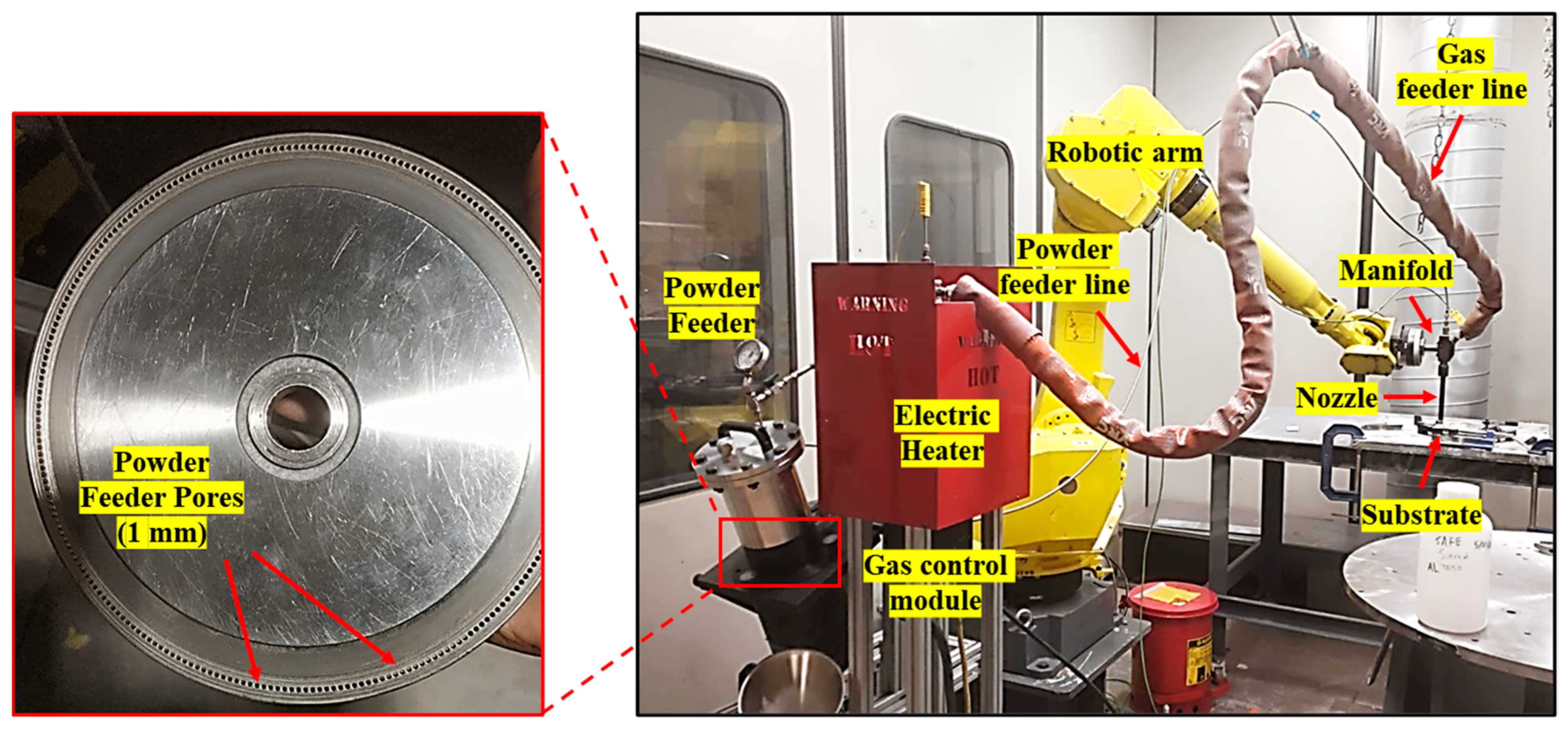
To manufacture bulk components from the cryomilled powders, an additive manufacturing approach based on HPCS deposition was employed. This solid-state technique enables the layer-by-layer deposition of metallic particles without thermal melting, thereby preserving the refined microstructure achieved through cryomilling. The deposition process was conducted using GEN IIITM advanced robotic CS equipment at VRC Metal Systems (Box Elder, SD, USA), as illustrated in Figure 2. The system’s high kinetic energy and precise robotic control facilitated uniform build-up and strong interparticle bonding, making it particularly suitable for consolidating NC powders into dense, near-net-shape components.
In a typical HPCS process, an inert carrier gas (typically nitrogen or helium) is used to accelerate powder particles to supersonic velocities. The process begins by loading the cryomilled powder into the equipment’s powder feeder unit. Concurrently, nitrogen gas enters the gas control module, where it is split into two separate paths. One stream is directed into the powder feeder to transport the powder toward the nozzle, while the second stream is passed through a heating system, elevating the gas temperature to approximately 400 °C. These streams are subsequently merged at a manifold positioned just upstream of the nozzle entrance. The resulting powder-gas mixture is accelerated through a converging–diverging de Laval nozzle, reaching particle velocities over 600 m/s. The particles impact an Al 6061 substrate located at a standoff distance of 15 mm from the nozzle exit. Upon collision with the substrate, the particles undergo intense plastic deformation, promoting strong mechanical interlocking and localized metallurgical bonding. This deposition process is repeated layer-by-layer, gradually forming a dense, consolidated structure through solid-state accumulation of metallurgically bonded particles. Once the desired thickness is achieved, the deposited material is separated from the substrate using a horizontal milling setup in a CNC machine, yielding robust freestanding bulk specimens suitable for downstream mechanical, tribological, and microstructural evaluation.
In the current study, the focus is on obtaining high deposition thickness to make bulk components. Table 1 presents the HPCS parameters used to obtain a thick coating were determined as per the industry standard for the CS of pure Al powders, and trial tests conducted with cryomilled Al powders. YSZ was also added during the CS process to obtain a thicker coating due to its high hardness, which helps in peening the deposited layer and improves deposition efficiency [31]. The addition of YSZ may also induce compressive stress, which can improve the mechanical properties of bulk components.
It is also important to note that the standard CS deposition process was stopped only in 3 cases: (1) if the powders in the powder feeder run out, (2) the powder feeder gas flow pressure reduces (particles getting stuck in the feeder), or (3) if the powder particles start causing intense pitting on the surface. This is because, once the pitting starts, the subsequent coating will keep increasing the pitted coating, making it a non-usable component.

2.3. Mechanical Testing

To evaluate the mechanical properties of CS’ed specimens, microhardness testing was performed using a Wilson® Tukon 1202 microhardness tester (Buehler, IL, USA), applying a load of 50 g with a dwell time of 10 s. Five indentations were made at random locations on each sample surface, and the average Vickers hardness was calculated to ensure reproducibility and minimize local variation.
In parallel, uniaxial tensile tests were conducted to evaluate the tensile strength and ductility of the CS’ed components. The tests were conducted using an Instron 3400 Series universal testing machine (UTM) under strain-controlled conditions. Specimens were machined into standard dog-bone geometries per ASTM E8 specifications for metallic tensile testing. All tensile tests were performed at a constant crosshead displacement rate of 0.1 mm/min until complete fracture.

2.4. Pin on Disk Tests

Scratch tests were conducted to evaluate the surface response under controlled mechanical loading conditions. The testing was performed over a linear distance of 10 mm at a constant sliding velocity of 2 mm/s. Normal loads of 20 N, 40 N, and 80 N were systematically applied using a precision RTEC MFT-5000 tribometer (RTEC Instruments, San Jose, CA, USA). H13 tool steel served as the counter surface due to its high hardness and thermal stability. CS’ed Al and Al-5Mg bulk components were used to make pins for scratch tests. The pins had a cylindrical cross-section with a 3 mm diameter and a hemispherical end. Each pin was subjected to four single scratches of 10 mm length at constant load. Separate pins were used for each applied load to avoid cumulative deformation. Figure 3 shows the scratch test setup on the tribometer, showing the tribo-pair in the magnified view. The scratch tests were first cconducted under dry conditions to determine the coefficient of friction (COF) and the transfer layer formation on the counterpart, and then under lubricated conditions using mineral oil, simulating realistic operating environments. The resulting tracks were then analyzed to assess friction behavior and wear mechanisms.

Estimation of Wear Volume, Wear Rate, and Wear Coefficients

In this tribo-pair, the pin material is relatively softer than the counter surface (steel) and undergoes wear during scratch tests, resulting in the flattening of the pin tip. To accurately estimate the wear volume, the geometry of this worn-out pin tip was analyzed to determine the overall material loss. The flat top diameter, D of the pin is measured using an optical microscope or a profilometer. Assuming that the wear scar forms a spherical cap on the pin tip, the wear depth, h can be derived using a geometric approach based on the profile of the worn surface using the following Equation (2):
h = R R 2 d 2 2
where R is the radius of the pin (1.5 mm), and d is the flat top diameter. Now, the amount of material loss or the wear volume, V lost from the pin tip can be calculated as the volume of the spherical cap removed, as given by the following Equation (3):
V = π h 2 3 R h 3
Since each pin was used for four scratches, the total wear volume was obtained as a cumulative value for the four scratches, L = 0.04 m. Now, to calculate the wear rate such that it reflects the intrinsic wear resistance of the material and allows meaningful comparison across different loads and materials, the specific wear rate, K was calculated by normalizing the wear volume with respect to both the applied load and sliding distance using the following Equation (4):
K = V F L
where F is the applied load (N) and s is the total sliding distance in meters. Additionally, the dimensionless wear coefficient, k was calculated to relate the experimental wear to fundamental material properties and provide a comparison across different materials, loads, and experimental conditions using classical Archard’s law Equation (5):
k = V H F L
where, H is the hardness of the softer material (pin).

2.5. Material Characterization

2.5.1. X-Ray Diffraction

To evaluate the crystalline structure and estimate the crystallite size of the samples, XRD analysis was carried out using a Bruker D8 Advance diffractometer (Bruker, Madison, WI, USA). The scans were performed over a 2θ range of 30° to 90°, with an angular increment of 0.01° and a dwell time of 0.1 s per step to ensure high-resolution data with optimal signal-to-noise ratio. The resulting diffraction patterns were analyzed using the standard reference JCPDS card (04-0787) for Al to identify peak positions. Crystallite size, internal lattice strain, and dislocation density were calculated through the Williamson-Hall (W-H) analysis, utilizing the full-width at half maximum (FWHM) values of selected diffraction peaks. The W-H equation is given in (6):
β T c o s θ = ε 4 s i n θ + K λ D
where β T is the peak broadening (radians), θ is the Bragg angle, ε represents microstrain, K is the Scherrer constant (taken as 0.94), λ is the X-ray wavelength (Cu-Kα radiation, λ = 1.54178 Å), and D is the average crystallite size. By plotting β T c o s θ against 4 s i n θ for multiple diffraction peaks, a linear fit is obtained. The slope of this line yields the lattice strain (ε), while the y-intercept corresponds to K λ D , from which the crystallite size is deduced. This analytical method allows simultaneous consideration of strain-induced and size-induced peak broadening, making it particularly suitable for materials processed through SPD methods such as cryomilling.
After crystallite size estimation, the dislocation density δ which indicates the density of line defects within the crystal lattice, was calculated using the following relationship (7):
δ = 1 D 2
where δ is expressed in units of nm−2 and D is the crystallite size in nanometers.

2.5.2. Microscopic Characterization

The morphological evolution of the powders before and after cryomilling was examined using SEM. Two systems were utilized: a JSM-6010LA InTouchScope SEM (JEOL, Tokyo, Japan) and an FEI Quanta 600 FEG SEM (FEI, Hillsboro, OR, USA). SEM analysis was performed under an accelerating voltage of 10 kV in secondary electron (SE) and backscattered electron (BSE) imaging mode to capture surface features, morphological, and compositional changes. Elemental mapping, particularly detecting the presence of Mg, was assessed via EDX integrated into the SEM systems.
For nanoscale analysis, TEM was conducted using a JEOL 2800 scanning TEM equipped with a field-emission gun (FEG). This allowed high-resolution imaging of both the cryomilled powders and the CS’ed bulk samples. Elemental mapping was performed using dual EDX detectors in the TEM to verify the distribution of Mg and Al.

3. Results and Discussion

3.1. Powder Processing

3.1.1. Morphology and Elemental Analysis of Powders

The morphological characterization of powders was carried out using SE imaging in SEM to analyze the effect of cryomilling. Figure 4a,b shows the morphology and particle size distribution of the as-received Al and Mg powders, respectively. The imaging revealed that the Al powders (Figure 4a) were predominantly irregular in shape, with smooth surfaces. In contrast, the Mg powders (Figure 4b) displayed an irregular morphology with rough surface texture and sharper edges. Figure 4c presents the morphology and particle size distribution of 8-h cryomilled Al–5Mg powders, showing irregular surface features indicative of extensive fracturing and plastic deformation. The cryomilled powders also exhibited a relatively narrow particle size distribution ranging primarily from around 20 to 45 μm, which is well suited for CS applications. It is also important to note that while most particles remained within acceptable size limits, agglomeration was occasionally observed, resulting from excessive cold welding of fragmented particles. These oversized particles were deemed unsuitable for deposition due to poor impact deformability and a tendency to rebound or cause nozzle clogging. This aligns with the findings reported through simulation studies that particle size uniformity, flow rate, and impact dynamics directly influence coating build-up within the de Laval nozzle [48]. In the present study, nozzle blockage was encountered during initial trials with unsieved cryomilled powder. To resolve this, all cryomilled powders were sieved using a −325 mesh (45 μm) screen to eliminate oversized agglomerates, thereby improving flowability and deposition consistency.
Figure 4d shows a closer examination of cryomilled powder, confirming the presence of surface cracks, cold-welded fragments, and fractured fragments as a result of repeated cycles of cold welding and fracturing. To confirm the compositional integrity of the cryomilled powder and evaluate the distribution of Mg, SEM-EDX analysis was performed. Figure 4e shows the EDX elemental mapping showing the distribution of Mg in the Al, implying successful mechanical alloying after the cryomilling process. Figure 4f shows the EDX plot for the elemental mapping, indicating a composition of 93.84 wt.% Al, 5.42 wt.% Mg, and 0.74 wt.% oxygen. The presence of oxygen, though minimal, suggests slight surface oxidation likely introduced during handling and post-processing exposure to ambient air.
The observed morphological and compositional changes confirm that cryomilling effectively promotes homogeneous alloying. This is critical in achieving strong particle bonding and high-density builds during CS deposition. However, careful control of particle size distribution and surface characteristics is essential to ensure optimal deposition efficiency and avoid nozzle clogging or coating defects.

3.1.2. Crystallite Size Refinement Through Cryomilling

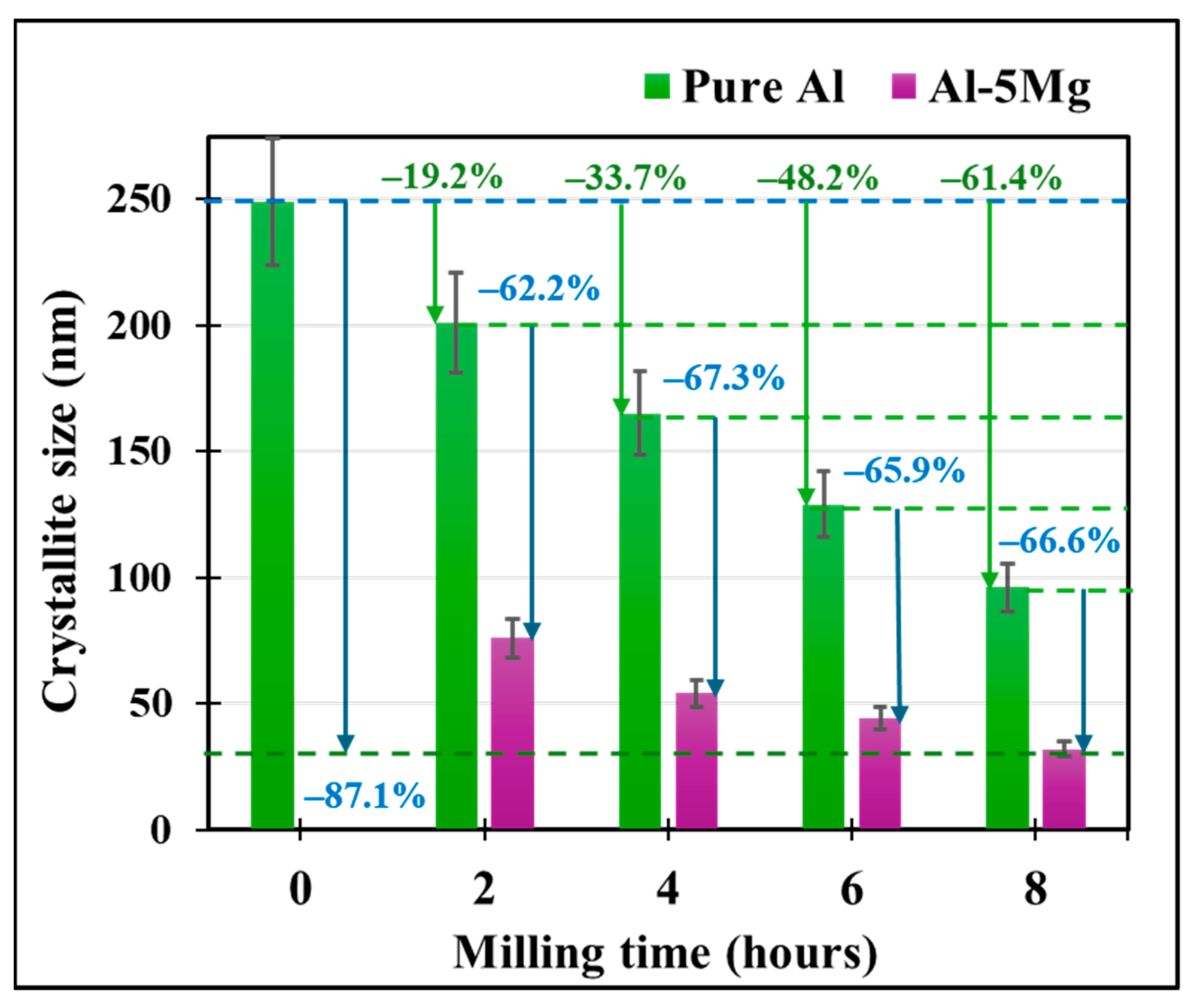
In addition to changing the morphology and surface features of the powders, the cryomilling process also significantly refines the crystallite size. Figure 5 shows the crystallite size evolution of both pure Al and Al-5Mg powders as a function of cryomilling duration. The results show a substantial decrease in crystallite size with increasing milling time, indicative of the progressive grain refinement characteristic of cryogenic mechanical alloying process. For pure Al powders, the crystallite size decreases from an initial value of 249 nm for the unmilled powders to 96 nm after 8 h of cryomilling, showing a 61.4% reduction. In comparison, Al-5Mg powders exhibit a more substantial refinement, with a reduction in crystallite size of approximately 87.1% to reach a minimum of 32 nm after 8 h of milling. This enhanced grain refinement in the Mg-doped system can be attributed to the segregation of Mg at the high-energy GBs, which lowers the interfacial energy, thereby improving thermodynamic stability. Additionally, Mg acts as a pinning agent at the GBs, effectively hindering the movement of dislocations and suppressing dynamic recovery (grain coarsening).
Grain coarsening is a common challenge in NC metals due to the thermodynamic instability of a huge volume of high-energy GBs associated with grain refinement. Under typical thermally activated conditions, these high-energy NC lattice structures tend to stabilize themselves by rearranging the atoms, leading to the formation of much coarser and stable grains. However, the method used in the current study employs cryogenic temperatures that significantly restrict such thermal activation, thereby impeding grain coarsening and promoting rapid size reduction. This suppression of thermal recovery enables a much faster and effective grain refinement within 4 to 8 h of cryomilling, which is substantially shorter than the 24 to 48 h often required for conventional HEBM systems [7]. Additionally, the embrittlement induced at low temperatures accelerates brittle fracture and promotes repeated cold welding. Furthermore, the presence of Mg enhances atomic diffusion and work hardening, increasing dislocation generation and further promoting crystallite fragmentation.
This combination of cryogenic temperature, high strain rates, and Mg doping thus creates a highly favorable environment for generating and stabilizing NC structures. These mechanisms collectively facilitate rapid structural refinement. Overall, these findings underscore the significance of solute-assisted GB strengthening in tailoring powder properties for advanced processing methods such as HPCS.

3.1.3. Dislocation Density and Micro-Strain Measurement

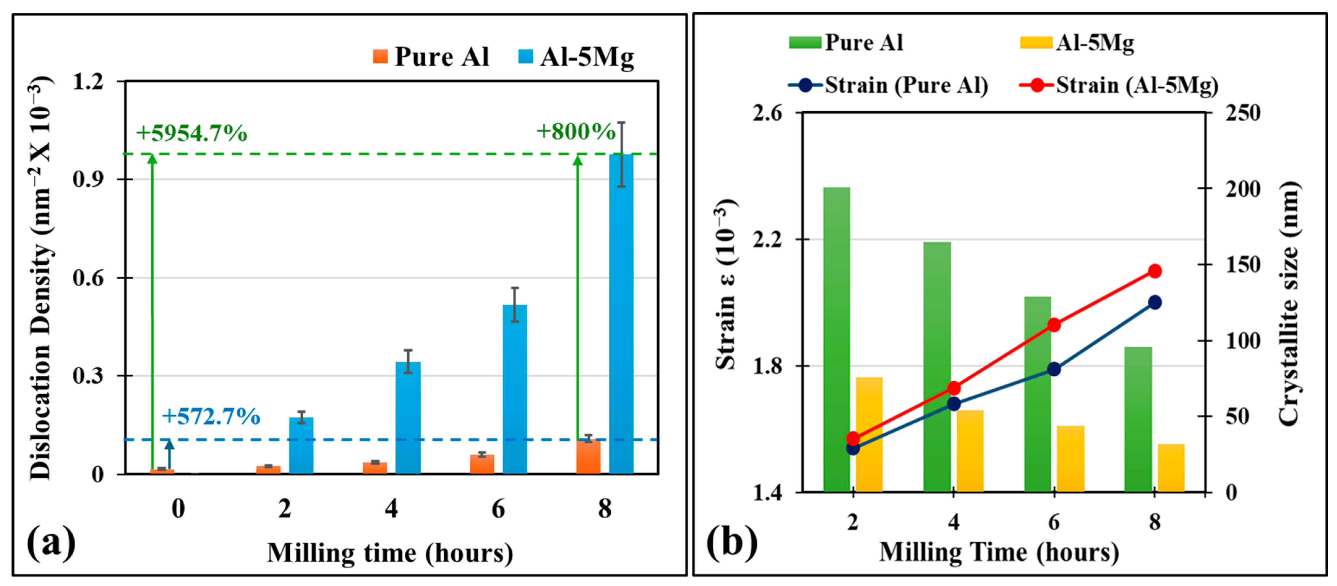
In addition to crystallite size refinement, cryomilling also substantially increases the dislocation density of the powders; a factor that directly contributes to mechanical strengthening. Figure 6a shows that the dislocation density for unmilled pure Al increased from 0.0161 × 10⁻³ nm−2 to 0.1085 × 10⁻³ nm−2 after 8 h of cryomilling, corresponding to a 572.7% increase. Remarkably, the Al-5Mg system displayed an even greater increase, reaching 0.9765 × 10⁻³ nm−2 which is approximately 60 times greater than that of the as-received pure Al powder, and 800% higher than that of cryomilled pure Al. These values were derived using the inverse-square relationship between crystallite size and dislocation density, highlighting the close coupling between microstructural refinement and formation of dislocations during SPD processes.
Besides crystallite size and dislocation density, micro-strain within the material can also be quantified using the W-H equation, which separates the size-induced and strain-induced contributions to peak broadening in XRD. Cryomilling is primarily an SPD process that introduces significant internal strain in the material as a result of its high strain rates. During cryomilling, the repeated fracturing, shearing, and cold welding of powder particles impose intense lattice distortion. These deformations lead to the generation of non-uniform strain fields, which manifest as broadening of the diffraction peaks in the XRD pattern. This accumulation of high levels of strain is particularly noticeable in NC powders, where GB densities are high and the resistance to dislocation motion promotes elevated internal stress states. Figure 6b shows that the internal strain levels for both the pure Al and Al-5Mg increased with an increase in milling time, as evidenced by XRD peak broadening and quantified via the W-H method. For pure Al, strain increased from 1.54 × 10⁻³ for 2 h of milling to 2.00 × 10⁻³ after 8 h of milling. Similarly, Al-5Mg powders also exhibited slightly higher strain across all durations, culminating in a value of 2.10 × 10⁻³ after 8 h of milling. These higher strain values for Mg-doped powders are attributed to solute-dislocation interactions at the GBs and enhanced resistance to dislocation motion as a result of Zener pinning, which amplifies the work hardening in the material.

3.1.4. Grain Boundary (GB) Stabilization Through Mg Segregation

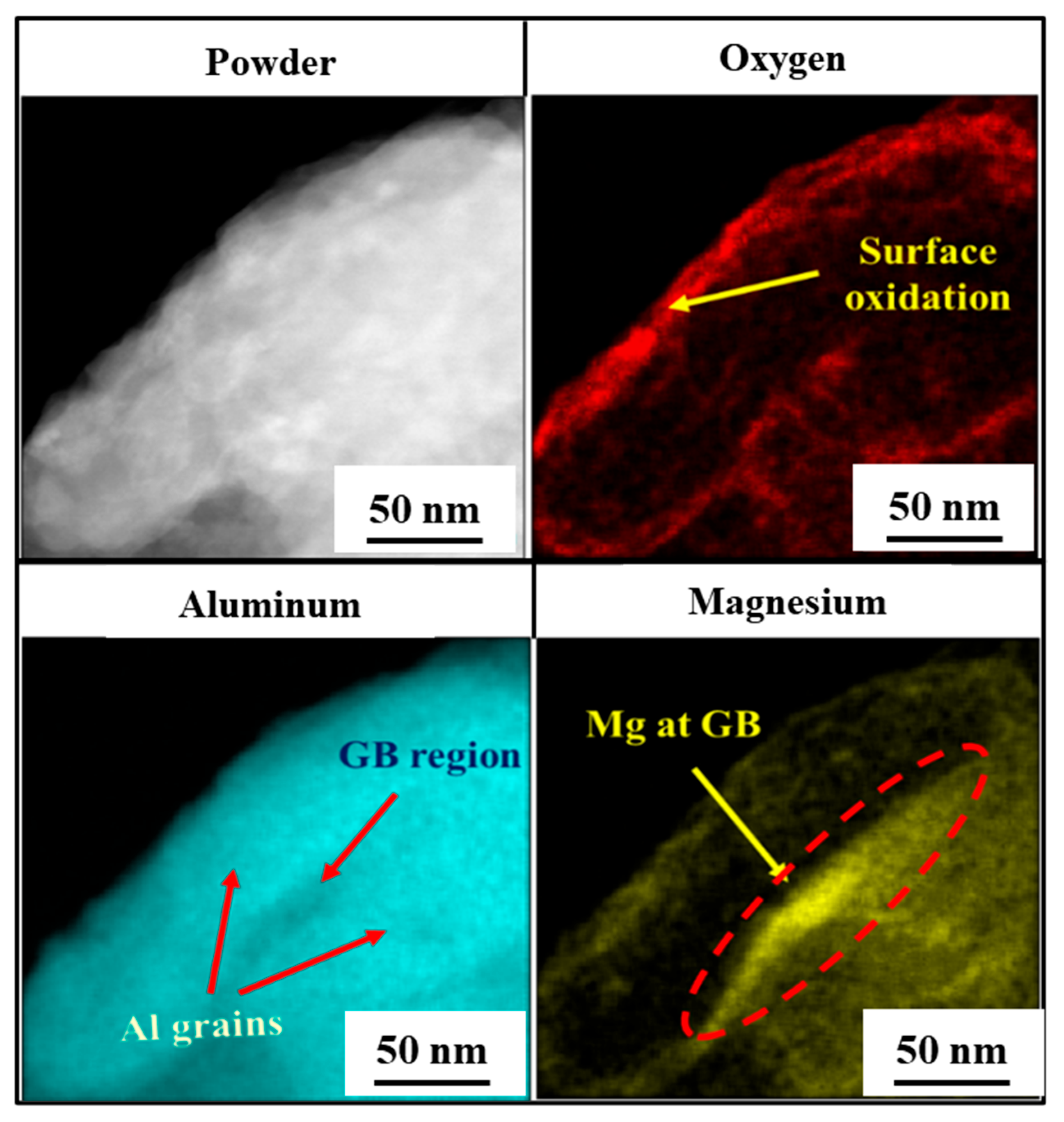
Despite the advantages offered by severe grain refinement, NC materials often suffer from intrinsic instability due to their high-energy GBs. In case of pure Al, the cryomilling process reduces the crystallite size at the cost of increased GB energy. These high-energy GBs induce thermodynamic instability, rendering the refined microstructure susceptible to grain coarsening even under moderate thermal exposure. However, the introduction of Mg as a dopant, which preferentially segregates at the GBs, alters this behavior. Figure 7 presents the TEM–EDX analysis of cryomilled Al–5 wt.% Mg powder showing the segregation of Mg atoms at GBs of Al, while the Al remains uniformly distributed. This preferential segregation provides clear evidence of Mg’s role in stabilizing the NC Al. Thermodynamically, this behavior is driven by the Al-Mg binary system such that the enthalpy of Mg segregation from Al is more favorable than its enthalpy of mixing, thereby promoting solute segregation at GBs [49].
Therefore, by lowering local interfacial energy and suppressing GB mobility, Mg segregation effectively inhibits grain growth to stabilize the GBs. This energy reduction mechanism enables the retention of ultrafine grains under cryogenic processing and post CS deposition conditions. These observations are consistent with the literature and simulation studies [37,50] that suggest that even small amounts of solute additions in NC materials with high-energy GBs can significantly improve microstructural stability. Thus, Mg plays a critical role in facilitating grain refinement during milling and maintaining the refined structure during post-processing, thereby resulting in improved structural integrity and performance of NC Al-based alloys.

3.2. Cold Spray (CS) Additive Manufacturing

CS technology has evolved into a versatile materials processing method, broadly categorized into: (1) low-pressure cold spray (LPCS) and (2) HPCS variants, each serving distinct applications. LPCS is predominantly employed for applying thin metallic coatings, typically in the range of a few microns, onto engineering surfaces. These coatings are designed to enhance tribological behavior by improving wear resistance, minimizing friction, and promoting lubricant retention. A common industrial example includes the deposition of titanium coatings onto ball bearings, which significantly improves their surface performance and operational lifespan under cyclic loading.
However, LPCS is generally limited in its capability to build substantial material volume, owing to relatively lower particle velocities and deposition efficiencies. In contrast, HPCS offers supersonic particle impact velocities by utilizing high-pressure carrier gases such as nitrogen or helium. This enhancement allows HPCS not only to deposit robust coatings but also to conduct structural repairs and manufacture bulk materials, particularly for temperature-sensitive alloys and geometries that are incompatible with traditional fusion-based processes like arc or laser welding. HPCS can also achieve a higher layer thickness (a few millimeters), enabling layer-by-layer additive manufacturing of components. The solid-state nature of the process ensures minimal thermal input, preserving phase stability and avoiding oxidation, grain growth, or distortion commonly associated with high-temperature techniques. This makes HPCS particularly useful for fabricating or repairing components in aerospace, automotive, and defense industries, where dimensional precision and thermal stability are critical [51,52].
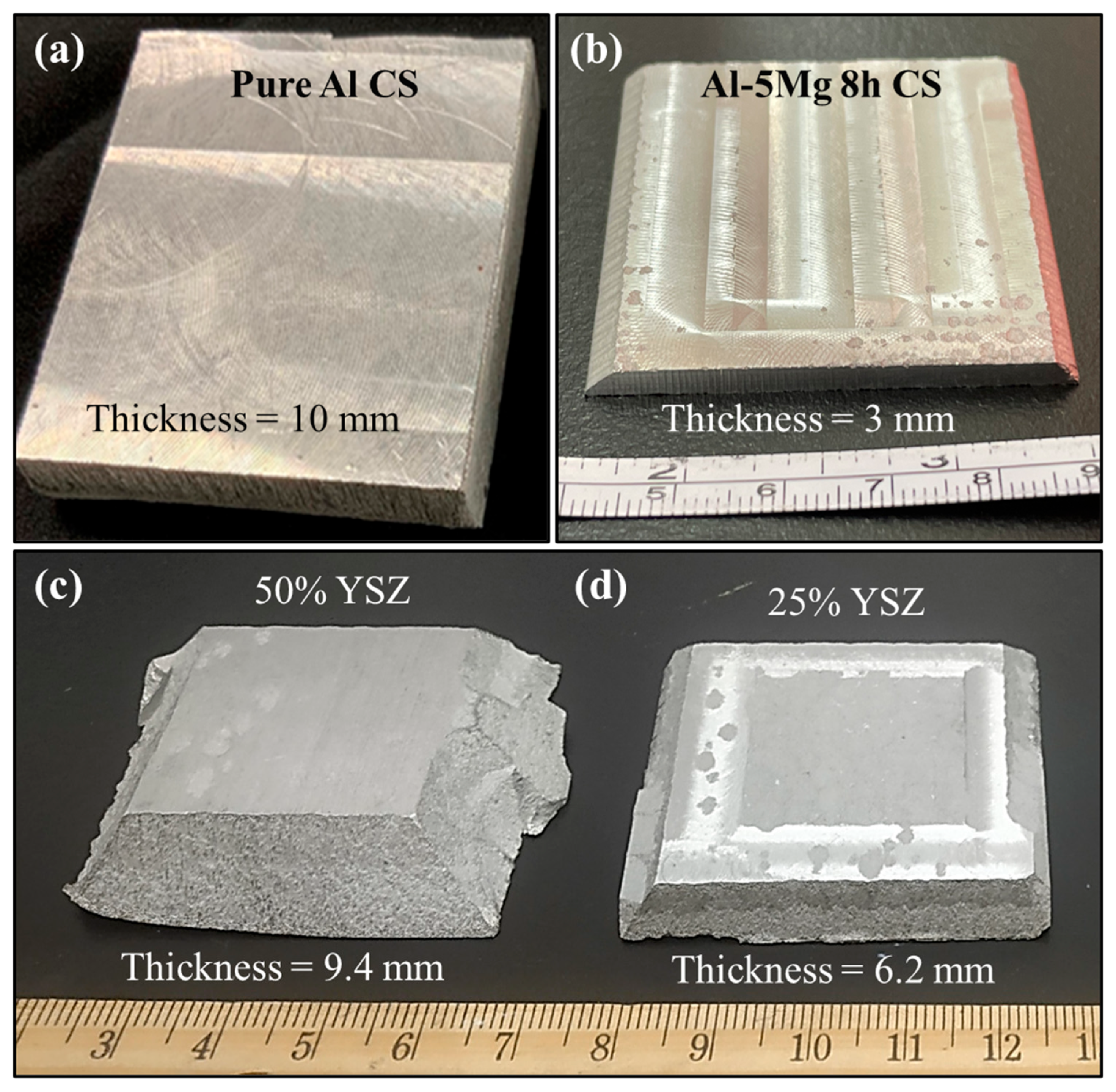
The HPCS process typically deposits material on the substrate surface (Al 6061). Upon collision with this substrate, the impacting particles undergo SPD, facilitating mechanical interlocking and localized metallurgical bonding with the substrate. Through successive layer-by-layer deposition, the HPCS process yields a dense, consolidated structure composed of interlocked and bonded particles. Following deposition, this consolidated structure (bulk component) is then separated from the substrate by precision CNC horizontal surface milling, allowing for the isolation of dense freestanding samples for further microstructural characterization and mechanical testing. The manufactured bulk components exhibited a density of approximately 98.8% of the theoretical density, indicating high deposition quality with minimal porosity. Figure 8a shows a free-standing HPCS deposited sample of 8-h cryomilled pure Al with a thickness of approximately 10 mm. In contrast, the corresponding Al-5Mg sample (Figure 8b), processed under identical spray conditions, achieved a significantly lower thickness of around 3 mm. This disparity is primarily attributed to the increased hardness of the Al–5Mg powders. During the HPCS process, the harder Al-5Mg particles exhibited reduced plastic deformation upon impact, inhibiting the formation of strong metallurgical bonds with the substrate. Consequently, a substantial portion of these particles rebounded rather than adhering, resulting in reduced material buildup per deposited layer despite identical spraying conditions.

3.2.1. Effect of YSZ Addition During CS Deposition

To address the inherently low deposition efficiency typically observed with cryomilled powders during the CS process, YSZ ceramic particles were introduced as a secondary phase for spraying Al-5Mg powders. The incorporation of YSZ aims to enhance deposition behavior by promoting localized plastic deformation through particle-assisted peening effects. This dynamic interaction is expected to facilitate improved particle-substrate bonding and increase the overall density and thickness of the deposited material. The presence of hard YSZ particles not only contributes to improving deposition efficiency but also induces beneficial compressive residual stresses within the coating, potentially enhancing mechanical performance such as hardness and wear resistance.
Figure 8c,d illustrates the standalone components obtained using CS Al-5Mg 8-h cryomilled powders with 50 wt.% and 25 wt.% additions of YSZ powders, respectively. Both samples exhibited a significant increase in the build-up thickness, reaching approximately 9.4 mm for the 50 wt.% YSZ and 6.2 mm for the 25 wt.% YSZ as compared to 3 mm for Al-5Mg 8-h cryomilled samples. This notable enhancement underlines the effectiveness of YSZ-assisted CS in improving layer consolidation and coating buildup in cryomilled feedstock systems. Figure 9a,b shows the embedded YSZ particles on the surface of Al-5Mg 8 h cryomilled components CS’ed with 50 wt.% and 25 wt.% YSZ. The particle matrix bonding at the surface of each YSZ particle is similar to that of a metal matrix composite (MMC) with ceramic reinforcements. These reinforcements can significantly enhance the mechanical properties by contributing to load-bearing capability, abrasion resistance, and overall hardness. These particles act as dispersed reinforcements within the metallic matrix, promoting localized strengthening and resistance to deformation under applied loads [53].
However, the reinforcing effectiveness of ceramic particles largely depends on the strength of their interfacial bonding with the surrounding metallic matrix. In CS processing, adhesion is primarily achieved through mechanical interlocking and localized plastic deformation. However, due to the inherently brittle nature and limited deformability of ceramic particles, establishing robust metallurgical bonding remains a significant challenge. This limitation often results in weak interfaces or particle-matrix debonding, particularly under bulk loading or elevated strain conditions, undermining the structural integrity of the composite. Therefore, while the inclusion of ceramic reinforcements can enhance hardness and wear resistance, insufficient bonding at the interface may detrimentally impact ductility and toughness [54]. Apart from this, the reinforcing YSZ ceramic particles were also observed to fracture upon impact and get embedded in the Al-5Mg matrix, as shown in Figure 9c. These fractured particle edges act as stress concentration sites for microcrack initiation.

3.2.2. TEM Analysis of CS Sample

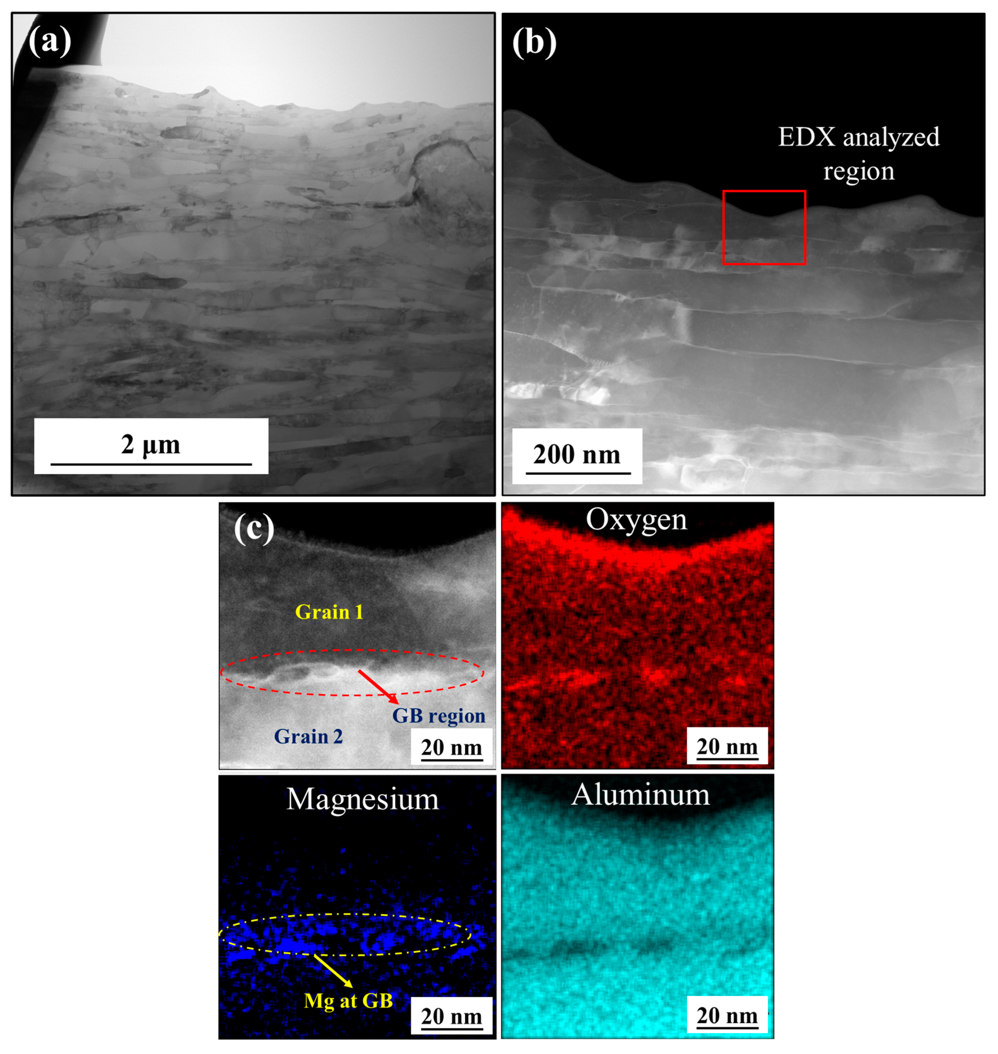
While TEM–EDX analysis of cryomilled powder confirmed the segregation of Mg at the GBs of Al, it is critical to assess whether this microstructural characteristic remains intact after the HPCS process. This is because, during deposition, cryomilled particles experience high-velocity impact, leading to significant localized heating, plastic deformation, and metallurgical bonding, all of which could influence the elemental distribution, introduce contamination, or trigger phase transformations. These thermomechanical effects raise the possibility of Mg redistribution, loss of boundary segregation, or interfacial contamination during deposition. Therefore, post-deposition characterization is necessary to determine the extent to which Mg segregation at GBs is retained, and to evaluate its implications for thermal stability and mechanical performance of the consolidated bulk material.
Figure 10a,b presents the bright field (BF) and dark field (DF) TEM images for the bulk Al-5Mg 8 h cryomilled CS samples. The TEM image shows the microstructure of the CS’ed sample, showing grains with elongated, non-equiaxed morphologies, aligned in a common orientation relative to the adjacent grains. This structural anisotropy and grain size reduction are primarily attributed to the SPD during the cryomilling process, which generates high strain rates. These elevated strains lead to intense shear forces that promote grain elongation and fragmentation, ultimately resulting in a refined, directionally oriented grain structure. To determine the presence of Mg at GB, TEM-EDX elemental analysis was conducted on a representative region as indicated in Figure 10b. Figure 10c presents a high-resolution view of a region within the CS’ed Al-5 Mg sample showing the elemental mapping. The results clearly indicate the presence of Mg at the GBs of the Al grains. This observation confirms that the segregation of Mg at GBs initially induced during cryomilling is retained throughout the CS process, with no appreciable elemental redistribution, interdiffusion, or phase decomposition.
This analysis demonstrates the capability of the HPCS technique to maintain the chemical and structural integrity of NC material, which is critical for ensuring the thermal stability and mechanical reliability of components fabricated via solid-state additive manufacturing.

3.3. Mechanical Properties

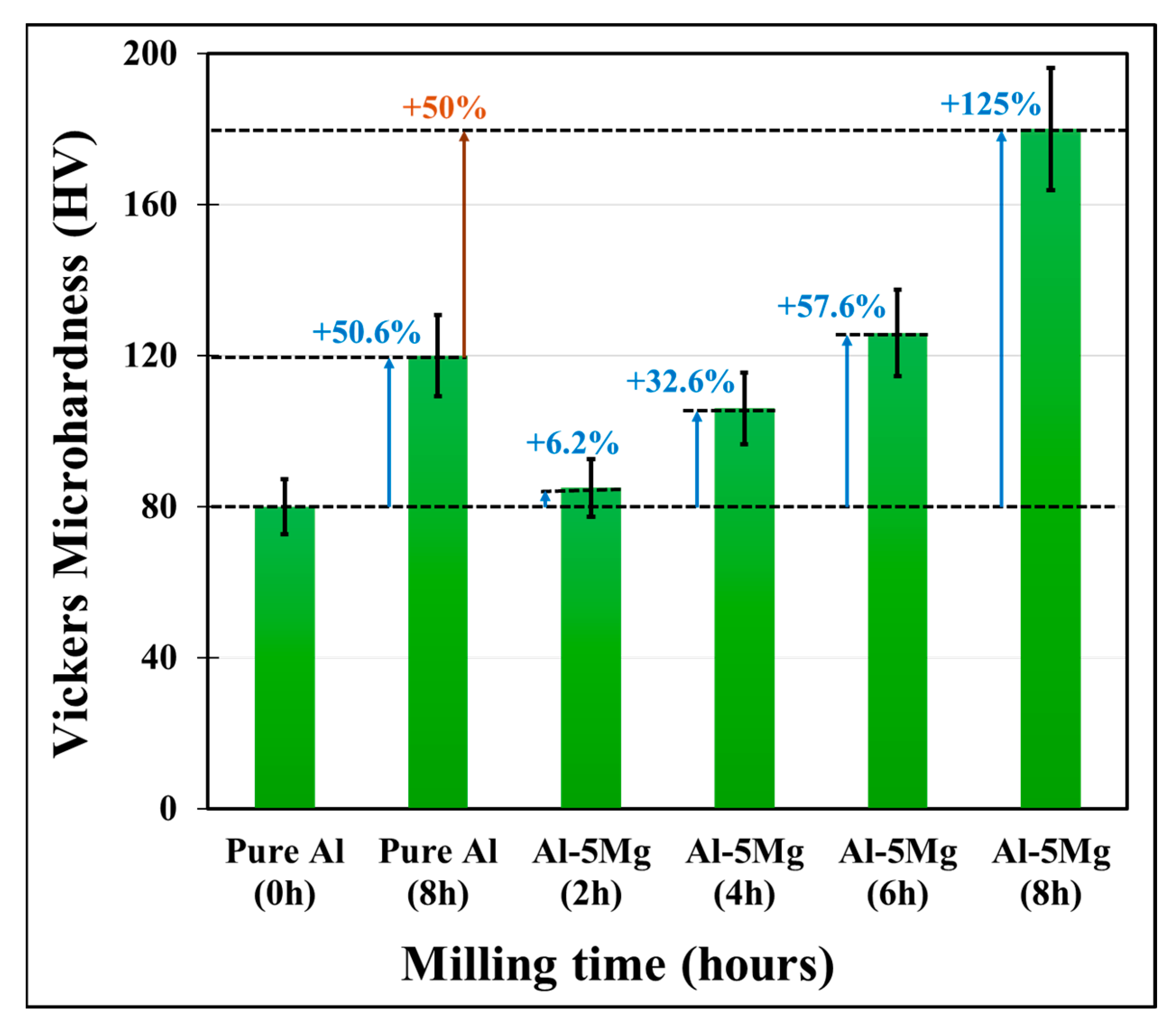
Crystallite size analysis using XRD confirmed that crystallite size consistently decreased with increasing cryomilling duration. According to the Hall–Petch relationship, this grain refinement directly enhances material hardness due to the increased volume fraction of GBs, which act as effective barriers to dislocation motion. Notably, Mg doping further promoted crystallite size reduction, which led to a more pronounced improvement in hardness. Figure 11 shows the variation in the Vickers microhardness for pure Al and Al-5Mg with an increase in cryomilling duration. The results show that the microhardness of CS’ed pure Al increased by 50.6%, reaching 120 HV after 8 h of cryomilling. In contrast, Al-5Mg CS samples exhibited a more substantial hardness increase with an increase in cryomilling duration. The 2-h cryomilled Al-5Mg sample recorded a hardness of 85 HV, which increased to 106.1 HV and 126.1 HV after 4 and 6 h of cryomilling, respectively. The maximum average hardness of 180 HV was observed for the 8-h cryomilled Al-5Mg sample, representing a 125% increase relative to the CS’ed pure Al sample.
To assess the tensile performance of the CS’ed samples, uniaxial strain-controlled tensile tests were performed on 8-h cryomilled pure Al and Al-5Mg specimens. Both materials exhibited relatively brittle failure characteristics, with limited strain to failure. Ultimate tensile strength (UTS) of pure Al was measured at approximately 142.9 MPa, while the Al-5Mg sample showed a significantly higher UTS of 289 MPa, a little more than double that of the pure Al counterpart (around 102.2% increase). In terms of ductility, the pure Al sample exhibited an elongation of around 1.84%, while the Al-5Mg sample showed ductility of around 3.51%. These values fall within expected ranges for CS’ed components where the additive deposition process produces a hybrid bonding network of mechanical interlocking and localized metallurgical bonding [52]. This kind of bonding leads to the formation of micron-scale interfacial voids and porosity, which serve as stress concentrators and promote premature crack initiation during tensile deformation [55]. Thus, the ductility of CS’ed components remains limited despite their refined microstructure and improved strength.
Overall, the significant enhancements in hardness and UTS are attributed to the synergistic effects of crystallite refinement and the GB stabilization by Mg. The presence of Mg atoms at GBs not only contributes to pinning dislocations but also mitigates grain growth, sustaining the refined nanostructure during the CS process. Therefore, these results highlight the efficacy of Mg doping in tailoring the mechanical performance of NC Al alloys.

Effect of YSZ Addition on Mechanical Properties

While the conventional HPCS process using cryomilled powders was effective in producing relatively thicker deposits (compared to coatings) suitable for component fabrication, limitations in the rate of buildup and overall deposition efficiency persisted. To address this, YSZ ceramic powders were introduced into the feedstock during the CS process, which resulted in a substantial increase in overall deposit thickness, enabling the formation of larger and more structurally robust components. This increase in deposition thickness is attributed to the role of YSZ in modifying particle-substrate interactions, promoting local particle anchoring, and potentially altering deposition dynamics by increasing surface roughness and interfacial friction. However, it is equally critical to quantitatively assess the mechanical properties of the deposited components to evaluate the extent of property evolution induced by the change in deposition process. Figure 12a illustrates the variation in Vickers microhardness as a function of cryomilling duration for CS’ed pure Al, cryomilled Al–5 wt.% Mg (8 h), and hybrid samples deposited with 25 wt.% and 50 wt.% YSZ ceramic powders. Notably, the incorporation of YSZ led to a substantial increase in microhardness. Specifically, the CS’ed samples with 25 wt.% and 50 wt.% YSZ exhibited higher hardness values of approximately 206 HV and 214 HV, respectively, corresponding to an increase of roughly 157.5% and 167.5% relative to the CS pure Al. This enhancement is attributed to the strain-induced hardening mechanisms activated during particle impact and consolidation.
However, the incorporation of YSZ particles into the CS’ed Al–5 wt.% Mg matrix resulted in a pronounced reduction in tensile properties, as shown in Figure 12b. For Al-5Mg powders cryomilled for 8 h, the addition of 25 wt.% and 50 wt.% YSZ led to UTS values of approximately 139.5 MPa and 128.7 MPa, respectively, representing decreases of 51.7% and 55.5% relative to the YSZ-free counterpart (289 MPa). Figure 12c presents the stress-strain curves for the corresponding bulk samples. The figure demonstrates a substantial increase in strength and ductility for the Al-5Mg samples cryomilled for 8 h, attributed to Mg doping. Conversely, the incorporation of YSZ leads to a marginal enhancement in ductility, which is likely due to the dispersion of YSZ particles that may act as stress concentrators, facilitating localized plasticity. However, this comes at the expense of reduced tensile strength, possibly due to the disruption of the metallic matrix continuity and a reduced load-bearing capacity. As the YSZ content increases from 25% to 50%, both strength and ductility exhibit a progressive decline, indicating a detrimental effect of excessive ceramic reinforcement on the mechanical performance. This deterioration in tensile properties is primarily attributed to the brittle nature of YSZ and the limited interfacial bonding between ceramic particles and the Al matrix, which likely promotes interfacial debonding, increased porosity, and microcrack formation under tensile loading. These localized defects may act as stress concentration sites and reduce the material’s capacity to withstand both elastic and plastic deformation. illustrating the trade-off between enhanced hardness and compromised tensile property in ceramic-reinforced CS’ed composites.

3.4. Tribological Properties

To comprehensively evaluate the tribological behavior of the fabricated materials, both dry and lubricated friction tests were performed using a single-pass scratch test methodology. The tests aimed to assess frictional response, track morphology, and material transfer under both dry and lubricated conditions, thereby offering insights into the tribological performance of cryomilled and CS’ed components.

3.4.1. Dry Friction Tests

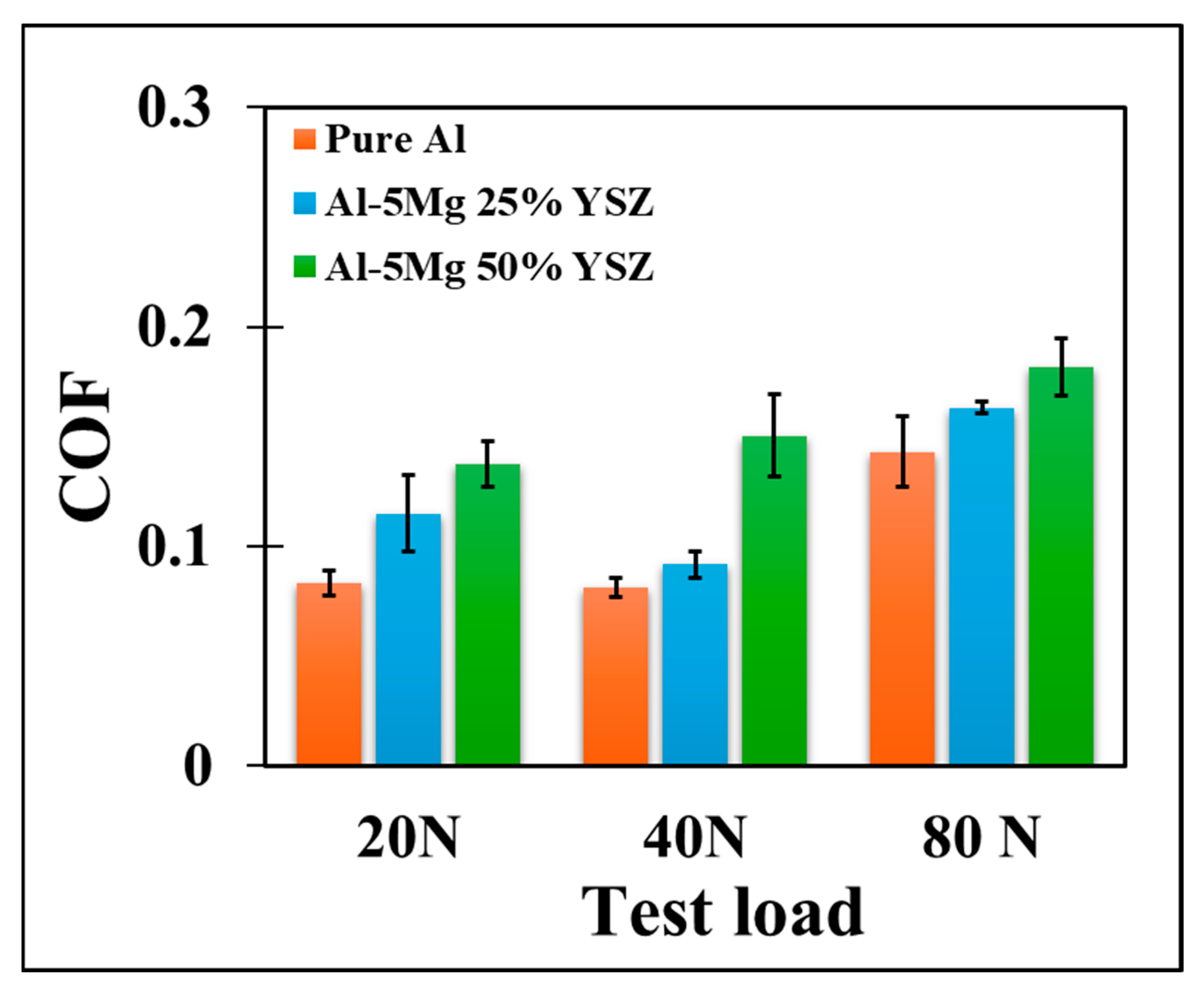
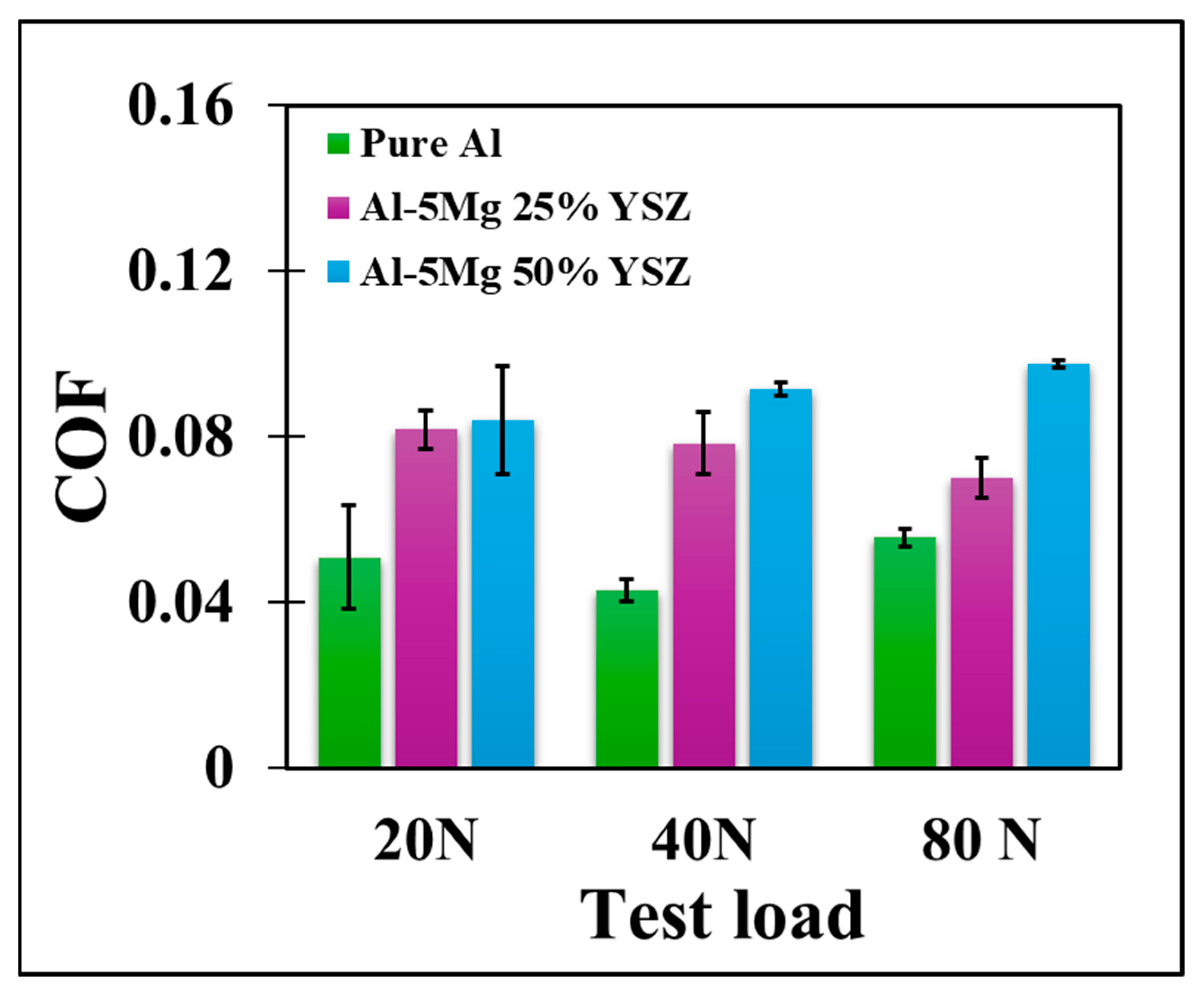
The dry friction tests were carried out in ambient temperature and humidity conditions. The pure Al or YSZ-reinforced Al-5Mg CS’ed samples were used as pins on the H13 tool steel counter surface, which is a high-hardness, wear-resistant alloy. The scratch tests were conducted multiple times and at varying loads of 20, 40, and 80 N and for a sliding distance of 10 mm. Figure 13 presents the dry friction test results for scratch tests for CS’ed samples. The results reveal that the COF increases with rising normal load (N) as well as with the increasing percentage of YSZ ceramic reinforcements. This trend can be attributed to several interrelated factors involving surface contact mechanics, interfacial adhesion (between the pin and harder counter surface), and the role of hard particle phases (YSZ) during tribological interaction. Under increasing test loads, the real area of contact between the sliding surfaces grows due to higher deformation at asperity junctions. For Al, this leads to increased adhesive interactions and material transfer, promoting greater resistance to sliding. Furthermore, elevated loads intensify the plowing and shearing actions at the interface, resulting in greater energy dissipation and, thus, a higher COF.
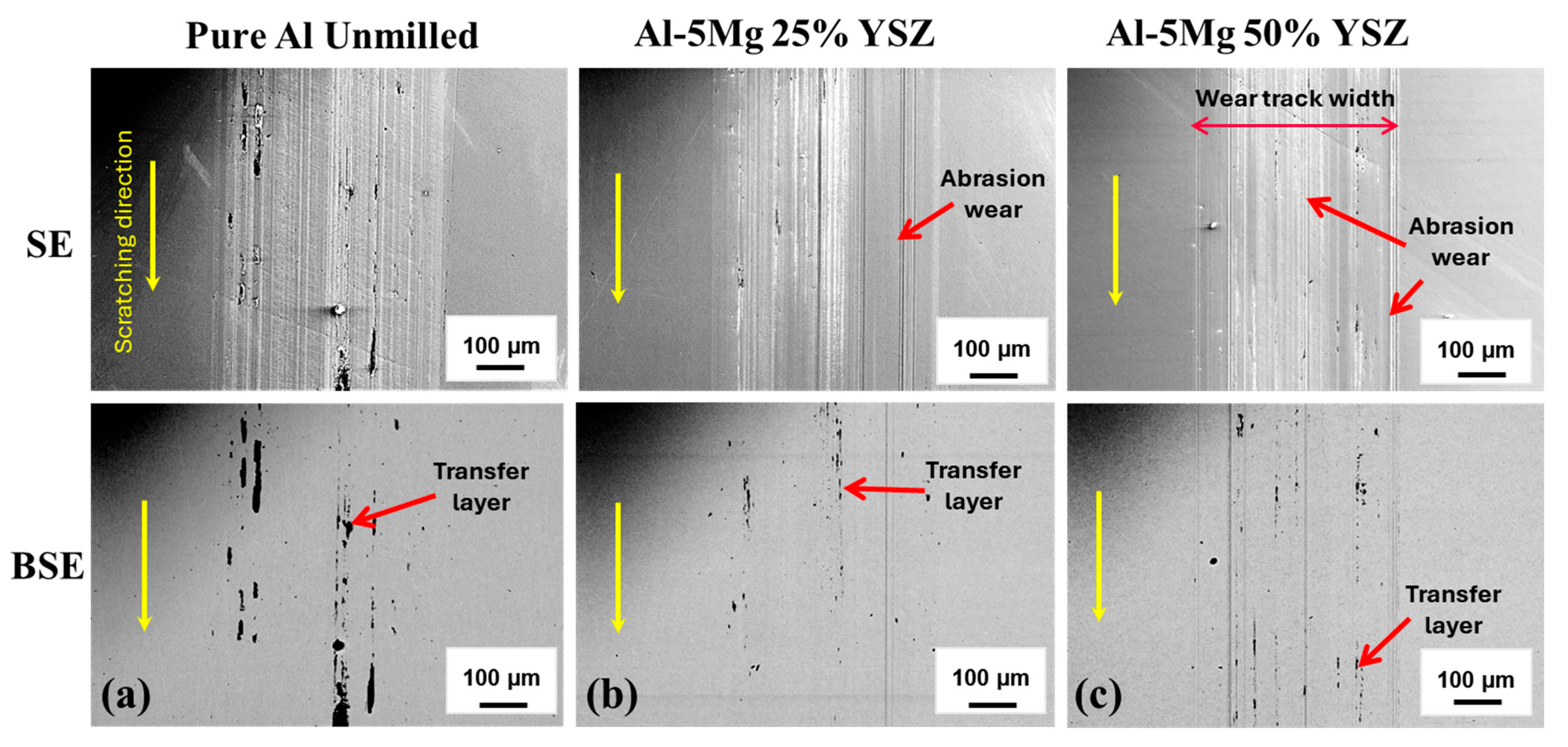
While the incorporation of YSZ ceramic reinforcements enhances the hardness and wear resistance of Al-5Mg composites, it simultaneously introduces additional complexity to their tribological behavior. Due to their intrinsic brittleness and high stiffness, YSZ particles embedded within the comparatively ductile Al-5Mg matrix disrupt surface continuity and increase contact roughness. Their presence at or near the contact interface promotes asperity interlocking and inhibits smooth plastic flow during sliding. The exposed ceramic phases increase interfacial shear stresses and intensify plowing mechanisms, both of which contribute to an increased COF under dry sliding conditions. Figure 14 presents the SE and BSE imaging in SEM showing wear track width, transfer layer, and abrasive wear for CS’ed samples. The BSE image shows a high amount of transfer layer for unmilled pure Al, indicating an adhesive mode of friction. The softer material (Al) wears out and forms a transfer layer on the counter surface (Figure 14a). However, with the introduction of the YSZ, the exposed ceramic particles contribute to the COF by introducing a shear stress and plowing of the counter surface, causing abrasive wear. The asperity interlocking and adhesion still lead to the formation of a transfer layer, as shown in Figure 14b,c.
In order to quantify the wear properties, the pin samples were then analyzed to calculate the overall material loss and the wear rate. Table 2 summarizes the calculated values for the respective wear volume, wear rate, and wear coefficients at varying normal loads for pure Al, Al-5Mg 25% YSZ, and Al-5Mg 50% YSZ samples. Each pin specimen underwent four successive scratches under identical loading conditions. Therefore, the total wear volume reported for each sample represents the cumulative material loss across all four scratches. This cumulative volume was subsequently used to determine the corresponding wear rates and wear coefficients. The results reveal that the wear volume increases with the increasing load, showing a consistent trend across all three material systems. For instance, pure Al exhibited a wear volume increase from 0.265 × 10⁻³ mm3 for 20 N load to 4.017 × 10⁻³ mm3 for 80 N load. Similarly, the Al-5Mg 25%YSZ showed an increase from 0.109 × 10⁻³ mm3 to 1.235 × 10⁻³ mm3 while Al-5Mg 50%YSZ demonstrated the lowest wear volumes, rising from 0.042 × 10⁻³ mm3 to 0.616 × 10⁻³ mm3 over the same load range. This progressive increase in wear volume and wear rate with load is attributed to enhanced asperity-asperity interactions at higher contact pressures. As the normal load increases, the real area of contact between the tribo-pair increases, intensifying localized stress and promoting material removal through plastic deformation and micro-fracture mechanisms. Apart from wear rate, wear coefficients were also calculated using Archard’s law, which relates wear volume to the applied load and the sliding distance, providing a normalized metric for comparative analysis. The reported values clearly show lower wear coefficients for YSZ-reinforced composites, which means that less material is removed per unit of load and sliding distance, suggesting the surface is more resilient to mechanical abrasion or adhesive wear. This further validates the improvement in wear resistance properties, particularly at higher levels of ceramic reinforcement.
In conclusion, pure Al exhibited the highest wear volumes and wear rates across all load levels, with material loss escalating sharply due to severe adhesive interactions and plastic deformation due to lower hardness. The lack of lubrication also facilitated greater metal-to-metal contact, promoting the formation and subsequent fracture of adhesive junctions, which contributed to accelerated wear and transfer layer formation. In contrast, the YSZ-reinforced composites demonstrated significantly improved wear resistance, with the Al-5Mg 50% YSZ sample showing the lowest wear volumes and wear coefficients. This enhancement is attributed to the presence of hard ceramic particles, which increase surface hardness, reduce the real area of contact, and act as micro-barriers against plowing and material transfer. Additionally, the reinforcement also helps distribute contact stresses more evenly, suppressing subsurface crack propagation and minimizing wear-induced damage.

3.4.2. Lubricated Friction Tests

To simulate realistic service conditions and minimize direct asperity-asperity contact, scratch tests were also conducted under lubricated conditions using mineral oil. The application of the lubricant creates a boundary layer condition that reduces interfacial shear stresses by minimizing asperity-asperity contact, mitigates frictional heating, and suppresses third-body abrasion. Therefore, this approach enables a more representative approach for evaluation of the tribological behavior of CS’ed YSZ reinforced Al-Mg composites simulating realistic operating environments such as in gears, bearings, or reciprocating engine components.
Similar to the dry conditions, the lubricated friction tests also showed a progressive increase in the COF with increasing normal load and YSZ reinforcement. However, across all tested conditions, the COF values remained significantly lower than those observed under dry sliding, highlighting the effectiveness of lubrication in reducing interfacial shear stresses and suppressing direct asperity-asperity contact (adhesion interactions), as presented in Figure 15. The increase in COF with load and ceramic content suggests a shift from boundary lubrication regime towards the mixed lubrication regime, where asperity contact still plays a role despite the presence of mineral oil. However, as normal load intensifies, the lubrication regime shifts left, allowing for a slightly greater asperity-asperity contact [56]. This results in elevated frictional resistance, particularly in the presence of rigid ceramic reinforcements such as YSZ, which protrude from the matrix and interact with the counter surface. Composites with higher YSZ content exhibited relatively higher COF under lubrication compared to unreinforced samples due to the surface-embedded YSZ particles disrupting lubricant film continuity and increasing micro-scale asperity interactions. These hard inclusions resist plastic deformation and act as local stress risers, amplifying plowing and shearing at the sliding interface despite the presence of lubricant.
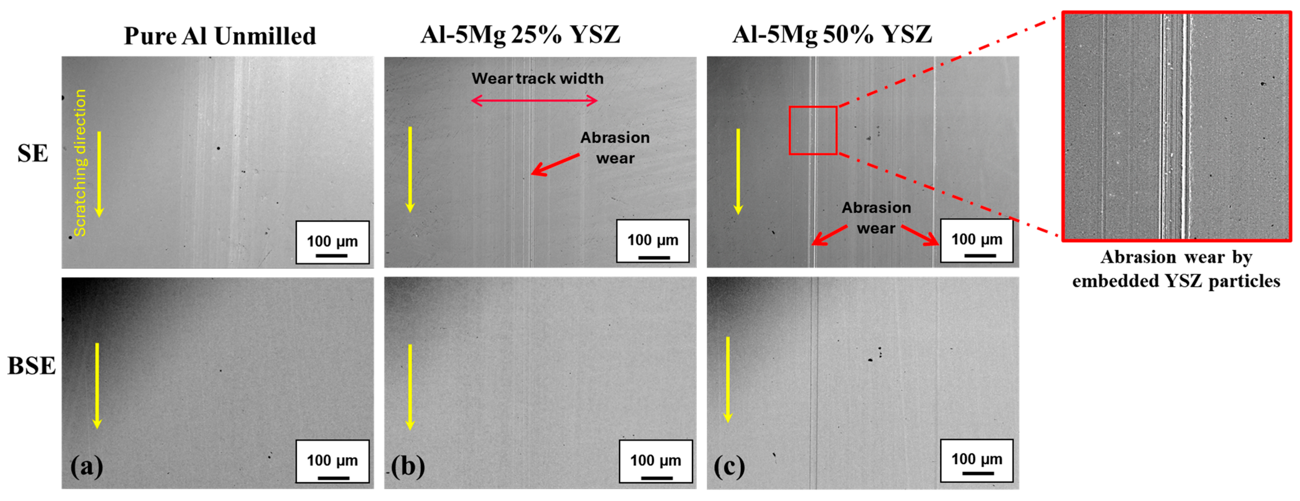
Despite the observed rise in COF with increasing test load and YSZ content, the overall frictional resistance under lubricated conditions remained significantly lower than that in dry sliding, confirming the efficacy of the lubricant in suppressing thermal buildup and limiting adhesive interactions. Figure 16 presents SE and BSE SEM images depicting wear track morphology for the CS’ed samples tested under lubricated sliding. Notably, the BSE images reveal an absence of transfer layers across all samples, indicating minimal adhesive wear and confirming the dominance of a mixed lubrication regime throughout testing.
However, with the increasing YSZ reinforcement, the width of the wear tracks broadens, and the severity of abrasive features intensifies, particularly in samples with higher YSZ content (Figure 16b,c). This trend correlates with the elevated COF values and suggests that, in the absence of significant adhesion, the primary friction mechanism transitions to plowing. The protruding YSZ particles act as rigid asperities that mechanically interact with the counter surface, disrupting lubricant film continuity and enhancing abrasive contact. These findings emphasize that, under lubricated conditions, friction is governed more by surface topography and third-body interactions than by interfacial adhesion.
Thereafter, the pin samples under lubricated sliding conditions were also analyzed to quantify the wear properties as presented in Table 3. The results revealed a consistent increase in wear volume with rising normal load across all material systems, reflecting the classical load-dependent nature of tribological degradation. Pure Al exhibited the highest cumulative wear volumes, escalating from 1.340 × 10⁻⁶ mm3 at 20 N to 16.581 × 10⁻⁶ mm3 at 80 N, indicative of its limited resistance to plastic deformation and adhesive wear. In contrast, the Al-5Mg 25%YSZ composite showed a marked reduction in material loss, ranging from 0.204 × 10⁻⁶ mm3 to 3.019 × 10⁻⁶ mm3, while the Al-5Mg 50%YSZ system demonstrated superior wear resistance, with volumes confined between 0.083 × 10⁻⁶ mm3 and 2.147 × 10⁻⁶ mm3 over the same load range. The corresponding wear rates, normalized by load and sliding distance, followed similar trends, with YSZ-reinforced samples exhibiting significantly lower values, especially at higher reinforcement levels. The wear coefficient further substantiated these findings, where the pure Al samples displayed the highest coefficients. At the same time, the 50% YSZ composite consistently yielded the lowest, underscoring its enhanced surface durability and reduced susceptibility to mechanical wear.
The enhanced wear resistance observed in YSZ-reinforced Al-5Mg composites under lubricated conditions is primarily attributed to the synergistic effects introduced by the ceramic particle dispersion. The incorporation of YSZ significantly elevates the surface hardness of the composite, thereby reducing susceptibility to plastic deformation, micro-plowing, and adhesive wear. Additionally, the hard ceramic phase contributes to more uniform stress distribution across the contact interface, mitigating localized stress concentrations that typically initiate subsurface damage and material removal. Beyond mechanical reinforcement, ceramic particles also play a critical role in stabilizing the boundary lubricating film. The embedded YSZ particles also promote micro-texturing and lubricant retention on the surface, which helps maintain separation between tribo-pair and suppresses direct asperity-asperity interaction. Collectively, these mechanisms help to significantly reduce wear volume, lower wear rates, and minimize wear coefficients.

3.4.3. Friction and Wear Mechanisms

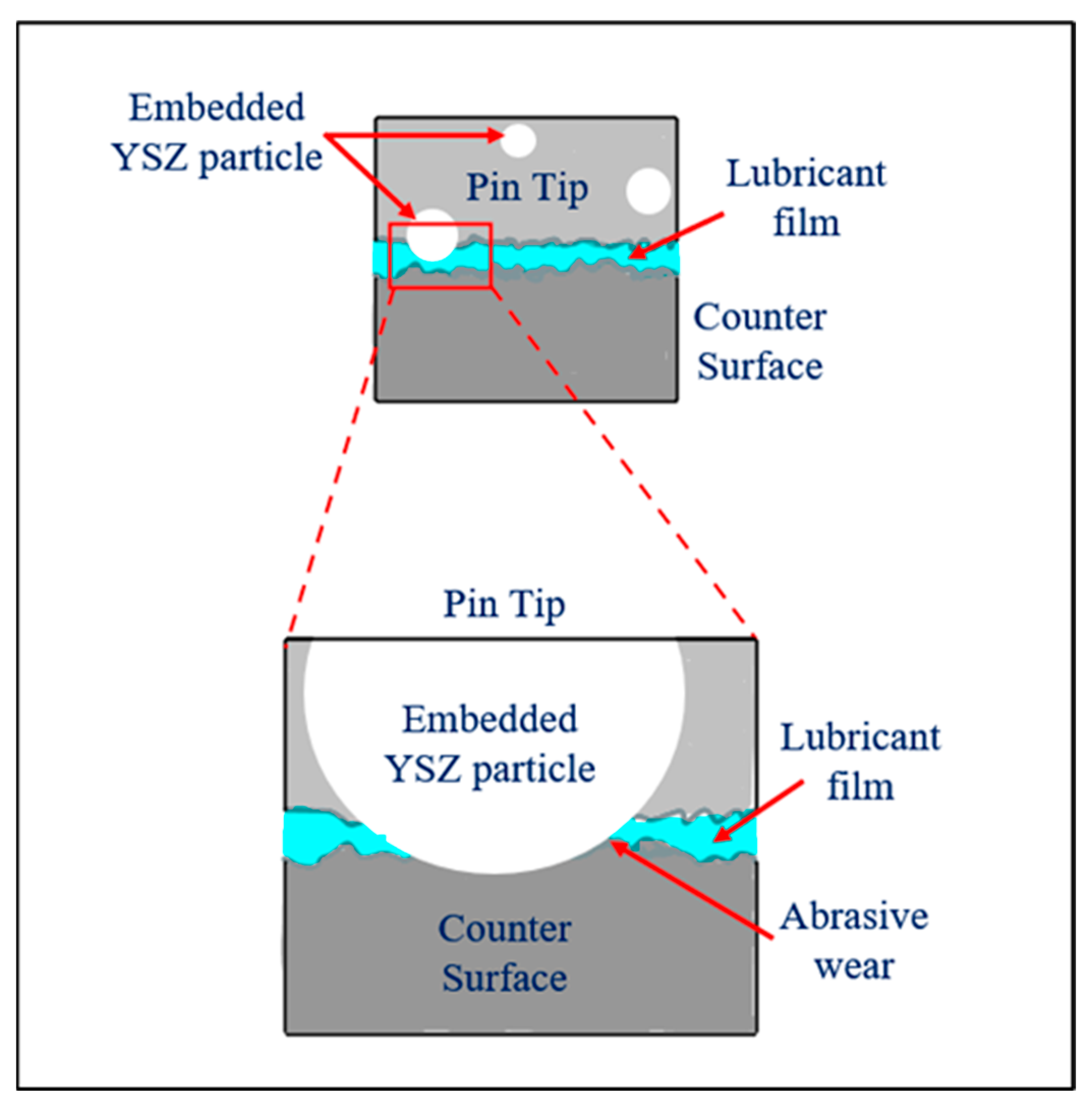
A representative schematic diagram of the friction and wear mechanism for the tribo-pair used in the current study is presented in Figure 17, showing the abrasive wear due to YSZ particles in the presence of the lubricant film. The tribological behavior of CS’ed YSZ reinforced Al-5Mg composites is governed by a dynamic interplay between adhesion, plowing, and third-body abrasion, each influenced by the test environment (dry vs. lubricated), applied load, and reinforcement content [57]. These mechanisms can be conceptually summarized using the fundamental expression (8):
μtotal = μadhesion + μplowing
In dry sliding conditions, where no lubrication is present, the adhesion component of friction dominates. As the normal load increases, the true contact area between asperities also rises due to plastic deformation of surface peaks. This enlarged contact area leads to stronger adhesive interactions at the interface, which results in an increased coefficient of friction (μdry) as given by Equation (9):
μdry = Adhesion friction (No μlubricated)
In reinforced samples, hard YSZ particles disrupted the smooth sliding interface, producing greater surface roughness and acting as third-body abrasives. These particles contributed to micro-grooving and surface plowing, resulting in additional frictional resistance. SEM analysis of worn surfaces revealed prominent wear tracks and fragmented transfer films, indicating a combination of adhesive and abrasive wear. Thus, the frictional load is shared between adhesive bonding and ceramic-induced micro plowing, amplifying friction as YSZ content increases, as given by Equation (10):
μdry = μadhesion + μplowing (both active)
By contrast, under lubricated conditions, the adhesive component is suppressed by the formation of a boundary lubricant film, effectively eliminating adhesive junctions. As a result, the frictional response shifts toward plowing-dominated behavior, especially in composite samples where YSZ particles disrupt the continuity of the lubricant film. Since the lubricant reduces the effective area of contact and aids in surface separation, the coefficient of friction (μlubricated) drops substantially compared to its dry counterpart.
While overall COF values under lubrication remain significantly lower than in dry tests, a gradual increase is still observed with both rising load and YSZ content. This is attributed to the high contact stress degrading the oil film, causing a left shift in the lubrication regime. The increase in COF is also attributed to localized plowing and shearing of the countersurface by protruding hard ceramic particles through the soft matrix. Overall, the friction in the lubricated conditions is given by Equation (11):
μlubricated = μplowing (adhesion suppressed)
In summary, the observed tribological response can be rationalized by considering the interplay of adhesion, plowing, and third-body abrasion. Table 4 presents the friction mechanisms and COF trends for different test conditions used in the current study. In dry conditions, enhanced adhesion drives up friction, while under lubrication, plowing and abrasive interactions, especially in the presence of YSZ particles, become more significant, ultimately shaping the overall wear and friction characteristics of the system.

4. Applications and Future Scope

The YSZ reinforced Al-5Mg composite system exhibits superior mechanical and tribological properties, making it useful for deployment in high-demand environments. Owing to the synergistic effects of grain refinement via cryomilling and reinforcement through YSZ particulates, the composite demonstrates improvements in hardness, tensile strength, and wear resistance. The single-pass scratch tests conducted under dry and lubricated conditions revealed substantial reductions in friction coefficients in lubricated tests, indicating superior resistance to adhesive and abrasive wear mechanisms. These properties support its usage in aerospace components, including structural casings, landing gear subassemblies, and actuator housing, where strength and surface stability are critical under cyclic loading and thermal fluctuations. Its abrasion resistance and minimal wear track formation also make it a viable material for tooling applications, including precision cutting tools and wear-resistant dies subjected to sliding contact and thermal cycling.
In the automotive sector, the composite’s enhanced hardness and tribological response are well-suited for brake rotors, cylinder liners, and piston rings, particularly in hybrid engine configurations where low friction and thermal stability are key to operational efficiency. Beyond transportation, the corrosion-resistant nature of the Al-Mg matrix, further stabilized by YSZ, extends its utility to marine applications such as pump housings and underwater fasteners. However, further studies on the corrosion performance of the material need to be conducted.
These mechanical and tribological performance attributes of stable NC Mg-doped alloys, coupled with the environmentally friendly nature of cryomilling and CS processing, also make it a promising solution for on-site restoration of vital components such as pumps, shafts, gear parts, fuselage, fasteners, etc., where conventional repair methods are impractical or logistically challenging, such as in aerospace and marine applications. The enhanced properties and broad application potential of the YSZ-reinforced Al-5Mg composite system affirm its viability for next-generation engineering materials, especially in applications demanding a high strength-to-weight ratio, superior tribological performance, thermal efficiency, and long-term durability.

5. Conclusions

The current study presents a hybrid approach for manufacturing bulk NC Al-5Mg alloys via cryomilling and HPCS. The addition of Mg dopant during the cryomilling process helps in stabilizing the NC structure and inhibits grain growth during CS deposition. This enables microstructural preservation without high-temperature processing, resulting in enhanced mechanical and tribological performance. Here are some broad conclusions of the current study:
  • Cryomilling process significantly refined crystallite sizes in Al-5Mg powders (~87.1% reduction), outperforming pure Al (~61.4%), due to segregation of Mg at GBs (as observed in TEM-EDX). This hinders dislocation motion and promotes a greater reduction in crystallite size.
  • The CS’ed Al-5Mg sample exhibited a UTS of 289 MPa, an increase of approximately 102.2% over pure Al (142.9 MPa), alongside improved ductility of 3.51% over 1.84% for pure Al.
  • Addition of YSZ powders helped in improving the deposition efficiency and the hardness by peening; however, the tensile strength reduces due to particle-matrix debonding during uniaxial loading.
  • The friction mechanism in dry friction conditions is primarily adhesion-dominated; however, with the addition of YSZ, the friction mechanism changes to a mix of adhesion and plowing.
  • In lubricated conditions, friction is plowing-dominated with minimal adhesion. With increasing YSZ content and load, the COF increases due to enhanced abrasive interaction.
  • Wear volume and wear rate increased with load for all materials; however, YSZ-reinforced composites exhibited significantly lower wear compared to pure Al, with the Al-5Mg 50% YSZ showing the best wear resistance due to enhanced hardness and reduced asperity-asperity interactions.
  • Under lubricated conditions, all materials demonstrated lower wear volumes and wear coefficients, with YSZ reinforcement further amplifying wear resistance by promoting stress distribution and lubricant film stability.
Overall, this study establishes a broadly applicable framework for enhancing the properties of NC alloys through secondary phase dopants, offering scalable solutions for diverse applications. This approach may also be helpful for in-situ repair of critical components, particularly in remote or inaccessible environments such as aerospace and marine systems.

Author Contributions

Conceptualization, M.M. and P.L.M.; methodology, A.K.K.; experimentation and analysis, A.K.K.; writing—original draft preparation, A.K.K.; writing—review and editing, A.K.K. and P.L.M.; supervision, M.M. and P.L.M.; funding acquisition, M.M. and P.L.M. All authors have read and agreed to the published version of the manuscript.

Funding

The authors acknowledge financial support from the US Department of Energy (DOE) within the project number DE-EE0009116.

Data Availability Statement

The original contributions presented in the study are included in the article, further inquiries can be directed to the corresponding author.

Acknowledgments

The authors acknowledge the support of the Department of Chemistry at the University of Nevada, Reno (UNR) for providing access to the powder diffractometer, acquired through NSF award CHE-1429768, for conducting XRD analysis. The authors are also grateful to VRC Metal Systems, Box Elder, SD, USA, for providing the HPCS facility, which enabled the successful execution of the additive manufacturing component of this study. The authors further acknowledge the valuable assistance of Brian Van Devener at the Nanofab facility, University of Utah, whose expertise and resources, supported by the USTAR program and NSF award DMR-1121252, were instrumental in conducting advanced material characterization. The authors also thank the Mechanical Engineering department and the Chemicals and Materials Engineering department for providing the needed laboratory resources and equipment for conducting this research.

Conflicts of Interest

On behalf of all authors, the corresponding author states that there is no conflict of interest.

Abbreviations

The following abbreviations are used in this manuscript:
NCNanocrystalline
AlAluminum
MgMagnesium
HPCSHigh-pressure cold spray
CSCold spray
XRDX-ray diffraction
SEMScanning electron microscopy
TEMTransmission electron microscopy
COFCoefficient of friction
GBGrain boundary
SPDSevere plastic deformation
HEBMHigh-energy ball milling
LN2Liquid nitrogen
N2Nitrogen gas
HIPHot isostatic pressing
SLSSelective laser sintering
EDXEnergy-dispersive X-ray spectroscopy
PCAProcess control agent
BPRBall-to-powder weight ratio
RPMRevolutions per minute
CNCComputer numerical control
YSZYttria stabilized zirconia
SLMStandard liters per minute
UTMUniversal testing machine
FWHMFull width at half maximum
JCPDSJoint Committee on Powder Diffraction Standards
ASTMAmerican society for testing and materials
SESecondary electron
BSEBackscattered electron
FEGField-emission gun
LPCSLow-pressure cold spray
BFBright field
DFDark field
UTSUltimate tensile strength

References

  1. Das, G.; Mazdiyasni, K.S.; Lipsitt, H.A. Mechanical Properties of Polycrystalline TiC. J. Am. Ceram. Soc. 1982, 65, 104–110. [Google Scholar] [CrossRef]
  2. Mahmood, M.A.; Chioibasu, D.; Ur Rehman, A.; Mihai, S.; Popescu, A.C. Post-Processing Techniques to Enhance the Quality of Metallic Parts Produced by Additive Manufacturing. Metals 2022, 12, 77. [Google Scholar] [CrossRef]
  3. Prangnell, P.B.; Bowen, J.R.; Apps, P.J. Ultra-Fine Grain Structures in Aluminium Alloys by Severe Deformation Processing. Mater. Sci. Eng. A 2004, 375–377, 178–185. [Google Scholar] [CrossRef]
  4. Birringer, R.; Gleiter, H.; Klein, H.-P.; Marquardt, P. Nanocrystalline Materials an Approach to a Novel Solid Structure with Gas-like Disorder? Phys. Lett. A 1984, 102, 365–369. [Google Scholar] [CrossRef]
  5. Meyers, M.A.; Mishra, A.; Benson, D.J. Mechanical Properties of Nanocrystalline Materials. Prog. Mater. Sci. 2006, 51, 427–556. [Google Scholar] [CrossRef]
  6. Kushwaha, A.K.; Maccione, R.; John, M.; Lanka, S.; Misra, M.; Menezes, P.L. Influence of Cryomilling on Crystallite Size of Aluminum Powder and Spark Plasma Sintered Component. Nanomaterials 2022, 12, 551. [Google Scholar] [CrossRef]
  7. Kushwaha, A.K.; John, M.; Misra, M.; Menezes, P.L. Nanocrystalline Materials: Synthesis, Characterization, Properties, and Applications. Crystals 2021, 11, 1317. [Google Scholar] [CrossRef]
  8. Baral, S.K.; Thawre, M.M.; Ratna Sunil, B.; Dumpala, R. A Review on Developing High-Performance ZE41 Magnesium Alloy by Using Bulk Deformation and Surface Modification Methods. J. Magnes. Alloys 2023, 11, 776–800. [Google Scholar] [CrossRef]
  9. Zhang, H.; He, Z.; Gao, W. Effect of Surface Severe Plastic Deformation on Microstructure and Hardness of Al Alloy Sheet with Enhanced Precipitation. Mater. Lett. 2023, 333, 133632. [Google Scholar] [CrossRef]
  10. Wu, B.; Fu, H.; Zhou, X.; Qian, L.; Luo, J.; Zhu, J.; Lee, W.B.; Yang, X.-S. Severe Plastic Deformation-Produced Gradient Nanostructured Copper with a Strengthening-Softening Transition. Mater. Sci. Eng. A 2021, 819, 141495. [Google Scholar] [CrossRef]
  11. Gebretsadik, B.T.; Ali, A.N. Improving the Fatigue Strength of Superelastic NiTi by Using Constrained Groove Pressing Severe Plastic Deformation Deform 3D Modeling and Microstructural Analysis. Mater. Sci. Eng. A 2023, 885, 145628. [Google Scholar] [CrossRef]
  12. Estrin, Y.; Vinogradov, A. Fatigue Behaviour of Light Alloys with Ultrafine Grain Structure Produced by Severe Plastic Deformation: An Overview. Int. J. Fatigue 2010, 32, 898–907. [Google Scholar] [CrossRef]
  13. Hamu, G.B.; Eliezer, D.; Wagner, L. The Relation between Severe Plastic Deformation Microstructure and Corrosion Behavior of AZ31 Magnesium Alloy. J. Alloys Compd. 2009, 468, 222–229. [Google Scholar] [CrossRef]
  14. Kumar, N.; Biswas, K. Cryomilling: An Environment Friendly Approach of Preparation Large Quantity Ultra Refined Pure Aluminium Nanoparticles. J. Mater. Res. Technol. 2019, 8, 63–74. [Google Scholar] [CrossRef]
  15. Wang, S.G.; Liu, S.Y.; Sun, M.; Tian, B.H.; Zhang, Z.D. Improved Tensile Properties, Stable Microstructures and Isotropic Deformation of Nanocrystalline 304 Stainless Steel. J. Mater. Res. Technol. 2023, 23, 331–347. [Google Scholar] [CrossRef]
  16. Chen, C.; Chen, Y.; Yu, J.; Liu, M.; Zhang, J. Microstructural Evolution and Multi-Mechanism Strengthening Model of Nanocrystalline Al-Mg Alloys. J. Alloys Compd. 2024, 983, 173905. [Google Scholar] [CrossRef]
  17. Khan, M.U.F.; Mirza, F.; Gupta, R.K. High Hardness and Thermal Stability of Nanocrystalline Mg–Al Alloys Synthesized by the High-Energy Ball Milling. Materialia 2018, 4, 406–416. [Google Scholar] [CrossRef]
  18. Polat, G.; Tekïn, M.; Kotan, H. Role of Yttrium Addition and Annealing Temperature on Thermal Stability and Hardness of Nanocrystalline CoCrFeNi High Entropy Alloy. Intermetallics 2022, 146, 107589. [Google Scholar] [CrossRef]
  19. An, X.; Lin, Q.; Wu, S.; Zhang, Z. Improved Fatigue Strengths of Nanocrystalline Cu and Cu–Al Alloys. Mater. Res. Lett. 2015, 3, 135–141. [Google Scholar] [CrossRef]
  20. Kushwaha, A.K.; Misra, M.; Menezes, P.L. Enhancement in Mechanical Properties of Bulk Nanocrystalline Aluminum by Grain Boundary Strengthening Mechanism. J. Mater. Eng. Perform. 2023, 34, 735–748. [Google Scholar] [CrossRef]
  21. Kale, C.; Srinivasan, S.; Sharma, S.; Hornbuckle, B.C.; Koju, R.K.; Grendahl, S.; Darling, K.; Mishin, Y.; Solanki, K. Exceptional Fatigue Strength of a Microstructurally Stable Bulk Nanocrystalline Alloy. Acta Mater. 2023, 255, 119049. [Google Scholar] [CrossRef]
  22. Zhang, J.; Jian, Y.; Zhao, X.; Meng, D.; Pan, F.; Han, Q. The Tribological Behavior of a Surface-Nanocrystallized Magnesium Alloy AZ31 Sheet after Ultrasonic Shot Peening Treatment. J. Magnes. Alloys 2021, 9, 1187–1200. [Google Scholar] [CrossRef]
  23. Morshed-Behbahani, K.; Farhat, Z.; Nasiri, A. Effect of Surface Nanocrystallization on Wear Behavior of Steels: A Review. Materials 2024, 17, 1618. [Google Scholar] [CrossRef] [PubMed]
  24. Suryanarayana, C.; Al-Joubori, A.A.; Wang, Z. Nanostructured Materials and Nanocomposites by Mechanical Alloying: An Overview. Met. Mater. Int. 2022, 28, 41–53. [Google Scholar] [CrossRef]
  25. Gil Sevillano, J.; Aldazabal, J. Ductilization of Nanocrystalline Materials for Structural Applications. Scr. Mater. 2004, 51, 795–800. [Google Scholar] [CrossRef]
  26. Froes, F.H.; Suryanarayana, C. Nanocrystalline Metals for Structural Applications. JOM 1989, 41, 12–17. [Google Scholar] [CrossRef]
  27. Pandey, V.; Seetharam, R.; Chelladurai, H.; Immanuel, R.J. Fabrication and Characterization of Al Alloy Composites Reinforced with Nanocrystalline Al4CrFeMnTi0.25 High-Entropy Alloy Particles via Double Ultrasonic Stir Casting for Aerospace Applications. J. Alloys Compd. 2025, 1010, 177900. [Google Scholar] [CrossRef]
  28. Qi, X.; You, J.; Zhou, J.; Qiu, K.; Cui, X.; Tian, J.; Li, B. A Review of Fe-Based Amorphous and Nanocrystalline Alloys: Preparations, Applications, and Effects of Alloying Elements. Phys. Status Solidi (a) 2023, 220, 2300079. [Google Scholar] [CrossRef]
  29. Bewilogua, K.; Bräuer, G.; Dietz, A.; Gäbler, J.; Goch, G.; Karpuschewski, B.; Szyszka, B. Surface Technology for Automotive Engineering. CIRP Ann. 2009, 58, 608–627. [Google Scholar] [CrossRef]
  30. Dudnik, O.V.; Lakiza, S.M.; Marek, I.O.; Red’ko, V.P.; Makudera, A.O.; Ruban, O.K. Advanced Approaches for Producing Nanocrystalline and Fine-Grained ZrO2-Based Powders (Review) II. Wet Chemistry Methods: Hydrothermal, Solvothermal, and Supercritical Water Synthesis. Powder Met. Met. Ceram. 2025, 63, 532–548. [Google Scholar] [CrossRef]
  31. John, M.; Islam, M.S.; Misra, M.; Menezes, P.L. Understanding the Stress Corrosion Cracking Resistance of Laser Shock Surface Patterned Austenitic Stainless-Steel Weld Joints. Int. J. Adv. Manuf. Technol. 2024, 131, 4089–4105. [Google Scholar] [CrossRef]
  32. Kalita, P.; Ghosh, S.; Sattonnay, G.; Singh, U.B.; Monnet, I.; Avasthi, D.K. Radiation Response of Nano-Crystalline Cubic Zirconia: Comparison between Nuclear Energy Loss and Electronic Energy Loss Regimes. Nucl. Instrum. Methods Phys. Res. Sect. B Beam Interact. Mater. At. 2018, 435, 19–24. [Google Scholar] [CrossRef]
  33. Kushwaha, A.K.; Rahman, M.H.; Hart, D.; Hughes, B.; Saldana, D.A.; Zollars, C.; Rajak, D.K.; Menezes, P.L. 3-Fundamentals of Stereolithography: Techniques, Properties, and Applications. In Tribology of Additively Manufactured Materials; Kumar, P., Misra, M., Menezes, P.L., Eds.; Elsevier Series on Tribology and Surface Engineering; Elsevier: Amsterdam, The Netherlands, 2022; pp. 87–106. ISBN 978-0-12-821328-5. [Google Scholar]
  34. Nayak, S.; Bhushan, B.; Jayaganthan, R.; Gopinath, P.; Agarwal, R.D.; Lahiri, D. Strengthening of Mg Based Alloy through Grain Refinement for Orthopaedic Application. J. Mech. Behav. Biomed. Mater. 2016, 59, 57–70. [Google Scholar] [CrossRef]
  35. Murty, B.S.; Datta, M.K.; Pabi, S.K. Structure and Thermal Stability of Nanocrystalline Materials. Sadhana 2003, 28, 23–45. [Google Scholar] [CrossRef]
  36. Lu, L.; Tao, N.R.; Wang, L.B.; Ding, B.Z.; Lu, K. Grain Growth and Strain Release in Nanocrystalline Copper. J. Appl. Phys. 2001, 89, 6408–6414. [Google Scholar] [CrossRef]
  37. Hohl, J.; Kumar, P.; Misra, M.; Menezes, P.; Mushongera, L.T. Thermodynamic Stabilization of Nanocrystalline Aluminum. J. Mater. Sci. 2021, 56, 14611–14623. [Google Scholar] [CrossRef]
  38. Kushwaha, A.K.; Misra, M.; Menezes, P.L. Effect of Magnesium Dopant on the Grain Boundary Stability of Nanocrystalline Aluminum Powders during Cryomilling. Crystals 2023, 13, 541. [Google Scholar] [CrossRef]
  39. Yao, H.; Xu, X.; Luo, Y.; Han, T.; Zhou, Q. Microstructure and Properties of a HIP Manufactured SiCp Reinforced High Alloyed Al–Zn–Mg–Cu–Zr–Ti Aluminum Matrix Composite. J. Mater. Res. Technol. 2024, 30, 4856–4867. [Google Scholar] [CrossRef]
  40. Kushwaha, A.K.; Rahman, M.H.; Slater, E.; Patel, R.; Evangelista, C.; Austin, E.; Tompkins, E.; McCarroll, A.; Rajak, D.K.; Menezes, P.L. 1-Powder Bed Fusion–Based Additive Manufacturing: SLS, SLM, SHS, and DMLS. In Tribology of Additively Manufactured Materials; Kumar, P., Misra, M., Menezes, P.L., Eds.; Elsevier Series on Tribology and Surface Engineering; Elsevier: Amsterdam, The Netherlands, 2022; pp. 1–37. ISBN 978-0-12-821328-5. [Google Scholar]
  41. Hussain, T.; McCartney, D.G.; Shipway, P.H.; Zhang, D. Bonding Mechanisms in Cold Spraying: The Contributions of Metallurgical and Mechanical Components. J. Therm. Spray Technol. 2009, 18, 364–379. [Google Scholar] [CrossRef]
  42. Tejero-Martin, D.; Rezvani Rad, M.; McDonald, A.; Hussain, T. Beyond Traditional Coatings: A Review on Thermal-Sprayed Functional and Smart Coatings. J. Therm. Spray Technol. 2019, 28, 598–644. [Google Scholar] [CrossRef]
  43. Kafle, A.; Silwal, R.; Koirala, B.; Zhu, W. Advancements in Cold Spray Additive Manufacturing: Process, Materials, Optimization, Applications, and Challenges. Materials 2024, 17, 5431. [Google Scholar] [CrossRef] [PubMed]
  44. Yin, S.; Cavaliere, P.; Aldwell, B.; Jenkins, R.; Liao, H.; Li, W.; Lupoi, R. Cold Spray Additive Manufacturing and Repair: Fundamentals and Applications. Addit. Manuf. 2018, 21, 628–650. [Google Scholar] [CrossRef]
  45. Krebs, S.; Gärtner, F.; Klassen, T. Cold Spraying of Cu-Al-Bronze for Cavitation Protection in Marine Environments. J. Therm. Spray Technol. 2015, 24, 126–135. [Google Scholar] [CrossRef]
  46. Bandala, E.; Raymond, L.; Mitchell, K.; Rubbi, F.; Thella, J.; Osho, B.O.; Kushwaha, A.K.; Elahifard, M.; Su, J.; Zhang, X.; et al. Distance-Controlled Direct Ink Writing of Titanium Alloy with Enhanced Shape Diversity and Controllable Porosity. npj Adv. Manuf. 2025, 2, 4. [Google Scholar] [CrossRef]
  47. Kumar, A.; Rathor, S.; Vostrak, M.; Houdkova, S.; Kant, R.; Singh, H. Exploring Potential of Cold Spray Technology for Medical Devices: Current and Future Scenario. Mater. Today Commun. 2024, 40, 109534. [Google Scholar] [CrossRef]
  48. Ozdemir, O.C.; Widener, C.A. Influence of Powder Injection Parameters in High-Pressure Cold Spray. J. Therm. Spray Technol. 2017, 26, 1411–1422. [Google Scholar] [CrossRef]
  49. Ye, W.; Hohl, J.; Misra, M.; Liao, Y.; Mushongera, L.T. Grain Boundary Relaxation in Doped Nano-Grained Aluminum. Mater. Today Commun. 2021, 29, 102808. [Google Scholar] [CrossRef]
  50. Kushwaha, A.K.; Misra, M.; Menezes, P.L. Manufacturing Bulk Nanocrystalline Al-3Mg Components Using Cryomilling and Spark Plasma Sintering. Nanomaterials 2022, 12, 3618. [Google Scholar] [CrossRef]
  51. Krishnamoorthy, R.R.; Rozani, N.; Marius, D. Chapter Four—Mechanical and Stability Testing of Aerospace Materials. In Aerospace Materials; Sultan, M.T.H., Uthayakumar, M., Korniejenko, K., Mashinini, P.M., Najeeb, M.I., Krishnamoorthy, R.R., Eds.; Aerospace Engineering; Elsevier: Amsterdam, The Netherlands, 2025; pp. 75–101. ISBN 978-0-443-22118-7. [Google Scholar]
  52. Kushwaha, A.K.; Misra, M.; Menezes, P.L. Smart Manufacturing Approach to Manufacture Bulk Nanocrystalline Aluminum for Lightweight Applications. Int. J. Adv. Manuf. Technol. 2024, 134, 5175–5190. [Google Scholar] [CrossRef]
  53. Ghandvar, H.; Farahany, S.; Abu Bakar, T.A. A Novel Method to Enhance the Performance of an Ex-Situ Al/Si-YSZ Metal Matrix Composite. J. Alloys Compd. 2020, 823, 153673. [Google Scholar] [CrossRef]
  54. Ikubanni, P.P.; Mosadomi, A.O.; Adeleke, A.A.; Agboola, O.O.; Ajayi, S.A.; Adesina, O.S.; Faloye, O.T. Tensile and Fracture Behaviour of Aluminium MMCs with Ceramic Particles—A Review. Can. Metall. Q. 2025, 0, 1–30. [Google Scholar] [CrossRef]
  55. Rokni, M.R.; Nutt, S.R.; Widener, C.A.; Champagne, V.K.; Hrabe, R.H. Review of Relationship Between Particle Deformation, Coating Microstructure, and Properties in High-Pressure Cold Spray. J. Therm. Spray Technol. 2017, 26, 1308–1355. [Google Scholar] [CrossRef]
  56. Stephan, S.; Schmitt, S.; Hasse, H.; Urbassek, H.M. Molecular Dynamics Simulation of the Stribeck Curve: Boundary Lubrication, Mixed Lubrication, and Hydrodynamic Lubrication on the Atomistic Level. Friction 2023, 11, 2342–2366. [Google Scholar] [CrossRef]
  57. Gao, Z.; Li, Z.; Wen, G.; Wu, J.; Li, Y.; Zhao, Y.; Jin, M. Investigation of the Tribological Mechanisms of TiN-ZrO2-B4C Ternary Ceramic-Reinforced Copper-Metal Matrix Composites. Tribol. Int. 2024, 196, 109705. [Google Scholar] [CrossRef]
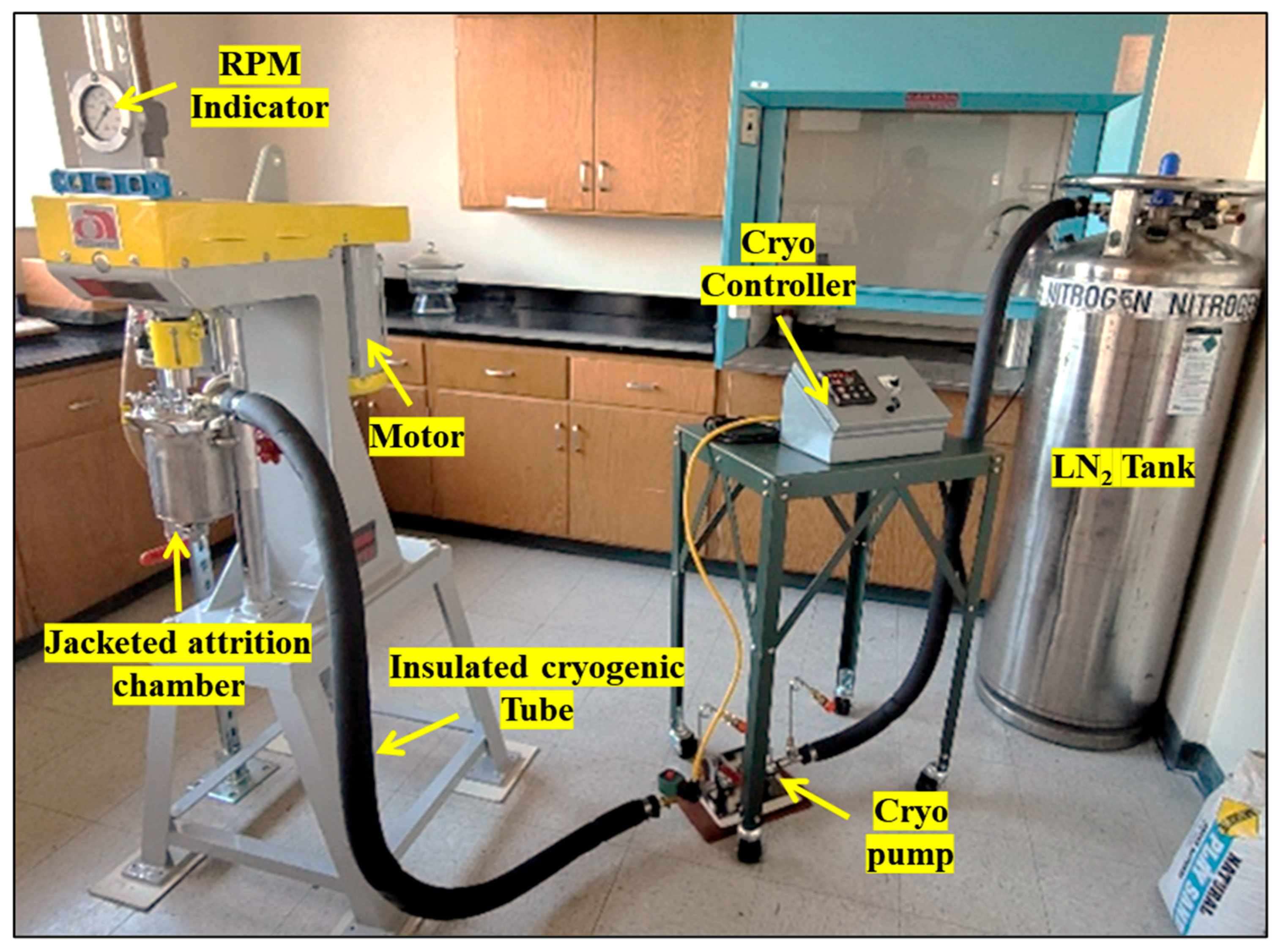
Figure 1. Cryogenic attrition milling setup.
Lubricants 13 00386 g001
Figure 2. GEN IIITM advanced robotic HPCS equipment showing the magnified view of the base of the powder feeder unit. (Image courtesy—VRC Metal Systems).
Lubricants 13 00386 g002
Figure 3. Scratch test setup on the tribometer showing the magnified view of the tribo-pair.
Lubricants 13 00386 g003
Figure 4. SEM micrograph showing the morphology and particle size distribution for (a) pure Al powders, (b) pure Mg powders, (c) Al-5Mg 8 h cryomilled powders, and (d) a magnified view of a cryomilled powder. (e) EDX elemental mapping and (f) EDX plot for Al-5Mg 8 h cryomilled powder.
Lubricants 13 00386 g004
Figure 5. Plot showing the variation in crystallite size with an increase in cryomilling milling durations for pure Al and Al-5Mg powders.
Lubricants 13 00386 g005
Figure 6. Plot showing the variation in (a) dislocation density and (b) internal strain with an increase in cryomilling milling durations for Pure Al and Al-5Mg powders.
Lubricants 13 00386 g006
Figure 7. TEM-EDX elemental mapping of 8 h cryomilled Al-5Mg powder showing the presence of Mg at the GBs of pure Al.
Lubricants 13 00386 g007
Figure 8. Free-standing CS’ed components manufactured using (a) Pure Al, and (b) 8 h cryomilled Al-5Mg powders. Standalone CS’ed samples of Al-5Mg 8 h cryomilled powders prepared with (c) 50% and (d) 25% addition of YSZ powders.
Lubricants 13 00386 g008
Figure 9. SEM imaging showing the embedded YSZ particles on the surface of Al-5Mg 8 h cryomilled components CS’ed with (a) 50% YSZ and (b) 25% YSZ. A magnified view of an embedded particle (c) showing a particle fracture.
Lubricants 13 00386 g009
Figure 10. TEM imaging showing the (a) DF image, (b) BF image (indicating EDX analyzed area), and (c) the elemental mapping using EDX for CS’ed Al-5Mg 8 h cryomilled component.
Lubricants 13 00386 g010
Figure 11. Plot showing the variation of Vickers microhardness with an increase in cryomilling duration for pure Al and Al-5Mg CS’ed components.
Lubricants 13 00386 g011
Figure 12. Plot showing the variation of (a) Vickers microhardness, (b) UTS, and (c) the corresponding stress-strain curves for CS’ed pure Al, pure Al 8 h cryomilled, Al-5Mg 8 h cryomilled, and Al-5Mg 8 h samples CS’ed with 25 and 50 wt.% of YSZ powders.
Lubricants 13 00386 g012
Figure 13. Plot showing the variation of COF for the dry friction scratch tests for CS’ed pure Al and YSZ reinforced Al-5Mg samples.
Lubricants 13 00386 g013
Figure 14. SE and BSE imaging in SEM showing wear track width, transfer layer, and abrasive wear for CS’ed (a) Unmilled pure Al, (b) 25% YSZ reinforced Al-5Mg, and (c) 50% YSZ reinforced Al-5Mg samples under dry friction conditions.
Lubricants 13 00386 g014
Figure 15. Plot showing the variation of COF for the lubricated friction scratch tests for CS’ed pure Al and YSZ reinforced Al-5Mg samples.
Lubricants 13 00386 g015
Figure 16. SE and BSE imaging in SEM showing wear track width and abrasive wear for CS’ed (a) Unmilled pure Al, (b) 25% YSZ reinforced Al-5Mg, and (c) 50% YSZ reinforced Al-5Mg samples under lubricated friction conditions.
Lubricants 13 00386 g016
Figure 17. Representative schematic diagram showing friction and wear mechanism for the tribo-pair.
Lubricants 13 00386 g017
Table 1. HPCS parameters used for the preparation of bulk components.
CS ParameterStandard Value
SubstrateAl 6061 alloy
Spray powderPure Al and cryomilled Al alloy powders
Spray additive (optional)YSZ
Spray pressure900 psi
Nozzle diameter2 to 6.3 mm
Spray Velocity>600 m/sec
Spray angle90° (Perpendicular to surface)
Standoff distance15 mm
Step size for raster1 mm
Powder feeder RPM12 RPM
Powder feeder gas flow150 SLM (standard liters per minute)
Powder feeder pore size1 mm
Carrier gas temperature400 °C
Carrier gas flow1715 SLM
Table 2. Calculated wear volume, wear rate, and wear coefficient at different loads under dry friction conditions.
Pin SampleLoad (N)Total Wear Volume
(×10−3 mm3)
Wear Rate
(×10−3 mm3/Nm)
Wear Coefficient
(×10−2)
Pure Al200.2650.3321.304
401.6101.0061.975
804.0171.2551.231
Al-5Mg 25YSZ200.1090.1361.372
400.3440.2151.086
801.2350.3860.974
Al-5Mg 50YSZ200.0420.0530.560
400.1740.1090.572
800.6160.1930.505
Table 3. Calculated wear volume, wear rate, and wear coefficient at different loads under lubricated friction conditions.
Pin SampleLoad (N)Total Wear Volume
(×10−6 mm3)
Wear Rate
(×10−6 mm3/Nm)
Wear Coefficient
(×10−5)
Pure Al201.3401.6756.579
404.7932.9955.879
8016.5815.1815.084
Al-5Mg 25YSZ200.2040.2552.579
400.7860.4912.477
803.0190.9432.380
Al-5Mg 50YSZ200.0830.1041.109
400.4240.2651.391
802.1470.6711.761
Table 4. Friction mechanisms and COF trends for different test conditions.
ConditionFriction MechanismCOF Trend
Dry, low YSZAdhesion-dominatedHigh COF, increases with load
Dry, high YSZMixed: Adhesion + Third-body abrasion (plowing)Even higher COF, enhanced wear
Lubricated, low YSZPlowing-dominated, minimal adhesionLow COF, stable with moderate load
Lubricated, low YSZReinforcement-driven micro plowing increases COFCOF increases with load and YSZ content
Disclaimer/Publisher’s Note: The statements, opinions and data contained in all publications are solely those of the individual author(s) and contributor(s) and not of MDPI and/or the editor(s). MDPI and/or the editor(s) disclaim responsibility for any injury to people or property resulting from any ideas, methods, instructions or products referred to in the content.