1. Introduction
Turbochargers (TCs) are widely used in modern internal combustion engines to increase power density by forcing more air into the cylinders. A key enabler of turbocharger performance is the bearing system, which must support high-speed rotating shafts while maintaining dynamic stability, minimizing friction losses, and ensuring durability. Among commercially adopted solutions, two types of hydrodynamic journal bearings are commonly employed: fully floating ring bearings (FFRBs) and semi-floating ring bearings (SFRBs) [
1].
The FFRB configuration features a floating ring that rotates freely between the shaft and housing, forming two concentric oil films—inner and outer [
2]. This design offers favorable load distribution and reduced friction under certain conditions but introduces complex dynamic interactions due to ring inertia, oil film coupling, and thermal effects. In contrast, the SFRB system constrains the ring’s rotation using a mechanical pin or stop, causing the outer oil film to function as a squeeze film damper (SFD), which significantly improves damping and stabilizes the rotor-bearing system [
3].
Although the structural differences between FFRB and SFRB systems appear subtle, they have substantial implications for rotordynamic performance. Turbochargers routinely operate at shaft speeds exceeding 200 krpm (thousands of revolutions per minute), crossing critical speeds and encountering unbalance excitation and oil-induced instabilities. Sub- and supersynchronous vibration modes, oil-whirl and whip phenomena, frequency jumps, and hysteresis effects all pose design challenges. These behaviors are further influenced by the lubricant’s physical properties, with oil temperature and pressure having pronounced effects on film thickness, damping, and power loss [
4].
A number of prior studies addressed these challenges. Macinnes and Johnston [
1] compared power losses in FFRB and SFRB systems, showing that FFRBs result in greater heat rejection under high oil pressure. San Andrés and Kerth [
5] highlighted the importance of thermal effects on floating ring behavior, showing decreased outer film clearance during operation. Holt et al. [
2] explored the influence of lubricant properties on subsynchronous motion under cold-start conditions, while Gjika et al. [
6] and San Andrés et al. [
7,
8,
9] conducted detailed experimental and modeling studies of turbochargers supported on SFRBs. These works established the critical role of nonlinear dynamics and lubricant conditions in determining stability margins.
Building on these foundations, additional studies provide further depth. Wang and Khonsari [
10] experimentally demonstrated hysteresis in the onset of rotor-bearing system instability, using a flexible Jeffcott rotor supported on oil film bearings. Their results showed that the instability threshold speed varies nonlinearly with oil temperature—ranging from 20 °C to 100 °C—and that even a single subsynchronous component can exhibit strong sensitivity to thermal conditions. Perge et al. [
11] investigated friction losses in automotive turbochargers with FFRBs, isolating bearing drag torque by eliminating aerodynamic effects. Their findings confirmed that power loss rises substantially with oil temperature and pressure, particularly above 100 krpm. In a related study, Eling et al. [
12] examined a high-speed Laval rotor supported on floating ring bearings, showing that oil feed conditions significantly influence both synchronous and subsynchronous response amplitudes, especially at elevated speeds. Notably, oil pressure primarily affected behavior at higher speeds, while oil temperature influenced power losses across the full speed range.
Liang et al. [
13] improved the predictive accuracy of numerical simulations for turbocharger vibration characteristics by using a three-dimensional thermohydrodynamic model. This sophisticated approach allowed them to resolve temperature and viscosity gradients across the oil film thickness.
San Andrés et al. [
4,
14,
15] conducted comprehensive numerical investigations into how oil supply conditions influence the performance of axially grooved semi-floating ring bearings (SFRBs). Their findings indicated that lower oil temperatures or elevated supply pressures increased heat generation due to shear within the oil film. Furthermore, while axial grooves were shown to enhance dynamic stability, they also introduced additional drag losses, with most heat dissipating through the lubricant. Building upon these insights, rotordynamic analyses were performed numerically, demonstrating that specific combinations of unbalance mass configurations could substantially reduce subsynchronous vibration. Machado et al. [
16] experimentally examined the influence of inner axial groove geometry in SFRBs on turbocharger vibration behavior, revealing that groove shape plays a critical role in determining the amplitude of both synchronous and subsynchronous vibrations.
Ryu and Yi [
17] proposed a novel SFRB design for turbochargers that incorporated wire mesh dampers to effectively suppress vibration levels. Similarly, Chatzistavris and Chasalevris et al. [
18] predicted the vibration characteristics of turbochargers equipped with wire mesh dampers, with their optimized design parameters resulting in the elimination of subsynchronous vibration components.
Koutsovasilis [
19] and Peixoto et al. [
20] highlighted the influence of the thrust bearing on the nonlinear lateral vibrations of the turbocharger. Ziese et al. [
21,
22] advanced numerical modeling by incorporating both a thrust bearing and a mass-conserving cavitation oil film model, replacing the traditional half Sommerfeld cavitation approach for greater accuracy. Zhang et al. [
23] conducted nonlinear transient analyses, revealing that a three-lobe floating ring bearing with preload significantly mitigates subsynchronous vibrations. Tarlani and Beris [
24] applied optimization techniques to determine bearing stiffness and damping parameters that minimize fluid reaction forces and displacement responses, subsequently predicting the dynamic characteristics of the turbocharger based on these force coefficients. However, their rotordynamic analysis was limited to a linear approach, and the predicted vibration modes, while stable, lacked experimental validation.
Zhang et al. [
25,
26] predicted the existence of stable operating regions contingent on the ratio of outer to inner oil film thickness and the oil supply temperature. Their findings indicated that a lower oil supply temperature leads to an expansion of the stable speed range. Furthermore, an appropriately introduced unbalance mass was shown to suppress subsynchronous vibrations and promote stable operation. Wang et al. [
27] investigated the effect of the phase angle of the unbalance mass on the dynamic behavior of a floating ring bearing (FRB) turbocharger, demonstrating that maintaining the phase angle between the compressor wheel and the turbine wheel within the range of 0 to 60 degrees significantly ensures stable operation. Zhong et al. [
28] predicted that in an FRB turbocharger, an increase in oil supply temperature causes outer oil film whirl to occur at lower speeds. Pesthy et al. [
29,
30] studied the jump phenomenon of subsynchronous frequency vibrations in relation to supply oil type, temperature, and pressure, finding that the speed at which this jump occurs increases with a high-pressure and low-temperature lubricant.
Despite these important contributions, there remains a lack of direct experimental comparison between FFRB and SFRB systems under matched, controlled test conditions. The present study addresses this gap by evaluating two commercial automotive turbochargers—one supported by FFRBs and the other by SFRBs—across a range of oil temperatures and pressures, with speeds reaching up to 200 krpm. Using cold compressed air to drive the rotors and employing high-speed data acquisition, triaxial accelerometers, and infrared (IR) thermal imaging, we investigated vibrational responses, instability onset, frequency jumps, and heat generation patterns.
This comparative analysis contributes original insights into the rotordynamic behavior and thermal performance of two bearing architectures, offering data-driven guidance for bearing selection in turbocharger systems. The results have strong implications for the design of next-generation turbochargers where durability, NVH (noise, vibration, and harshness) mitigation, and thermal efficiency are critical.
2. Experimental Facility
The experimental campaign was conducted using a purpose-built cold air-driven test rig designed to isolate and characterize the vibrational and thermal behavior of automotive turbochargers supported by FFRB and SFRB configurations.
Figure 1,
Figure 2 and
Figure 3 provide visual documentation of the bearing schematics, rig layout, and instrumentation setup.
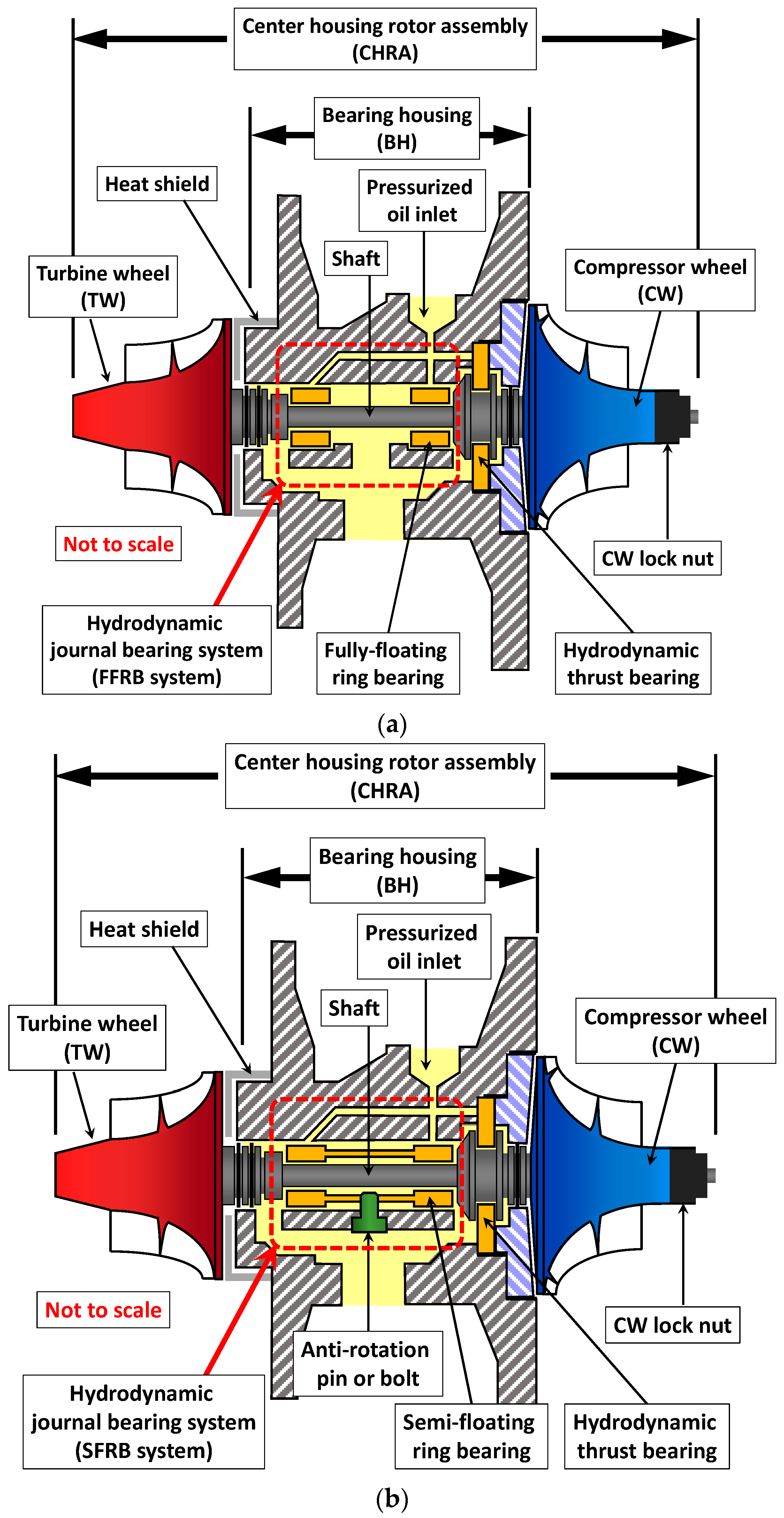
Figure 1 presents cross-sectional schematics of the two bearing configurations. In the FFRB system (
Figure 1a), the floating ring rotates between the shaft and the bearing housing, forming both inner and outer fluid films. This structure introduces dynamic complexity due to ring inertia and dual film interaction. In the SFRB configuration (
Figure 1b), ring rotation is mechanically constrained by a pin or a bolt, and the outer film acts as a squeeze film damper, providing additional damping without ring-induced instability. These schematic views are conceptual and not to scale but effectively highlight the structural differences.
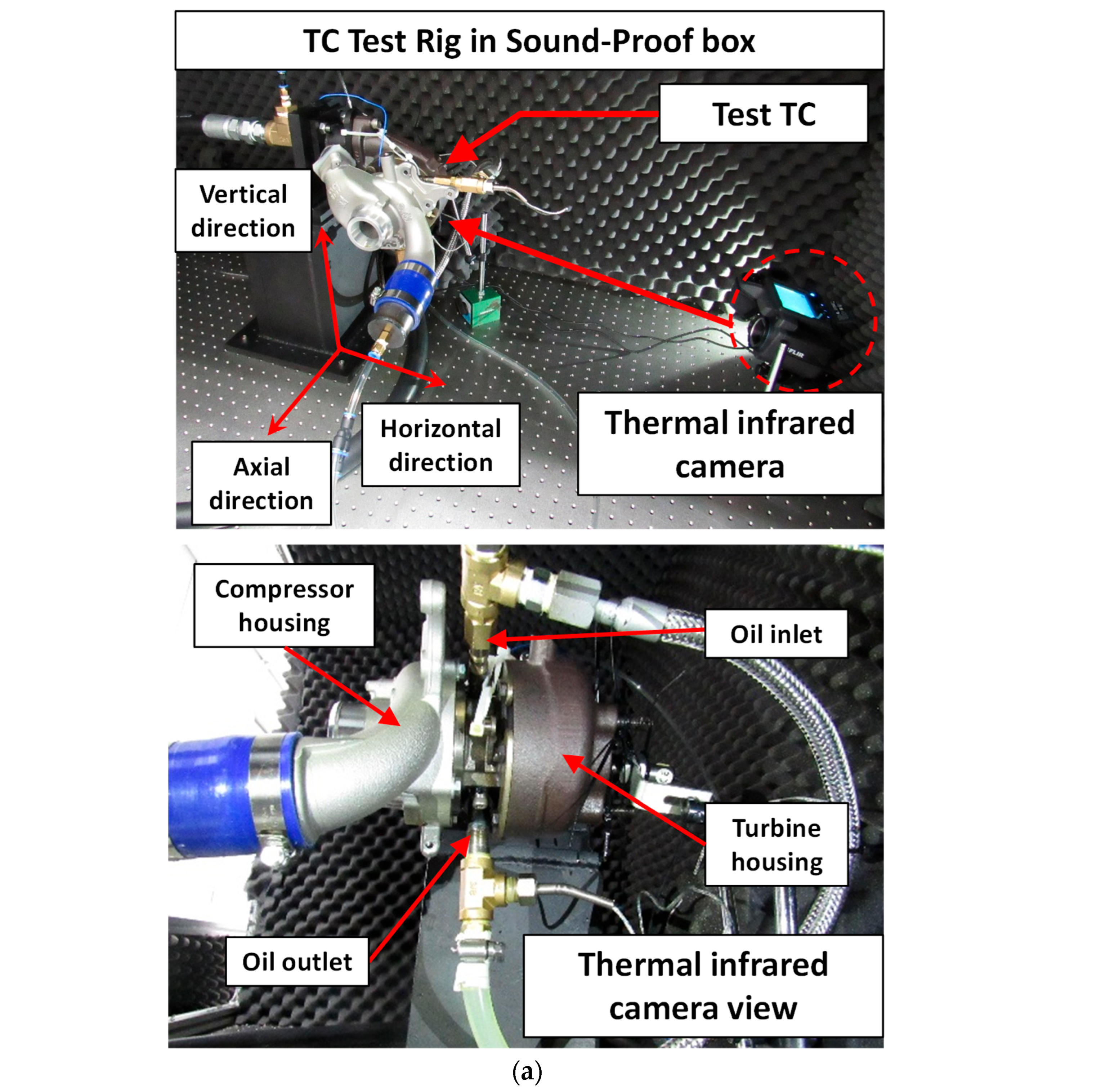
Figure 2a shows the assembled test rig inside an acoustic enclosure to minimize environmental noise. The turbocharger is mounted horizontally on an air-damped vibration isolation table, which reduces the influence of external disturbances such as those originating from the compressor or oil pump. Compressed air stored in high-capacity tanks is used to drive the turbine. A ball valve upstream of the turbine inlet provides manual control of rotor speed. To maintain consistent test conditions, the wastegate valve is fully closed, and the variable turbine geometry (VTG) vanes are fixed at their minimum opening angle.
Figure 2b depicts a schematic of the experimental loop. The lubrication system consists of an oil reservoir, electric gear pump (1 HP/750 W), bypass pressure relief valve, immersion-type electric heater, and thermocouple instrumentation. Oil (SAE 0W30) is supplied at a controlled flow rate and pressure, with inlet temperatures set between 30 °C and 70 °C. The system allows rapid switching between operating conditions to evaluate thermal and dynamic responses. A manual ball valve allows for simple changes in the supply pressure from 4 bar (g) to 2 bar (g) within approximately 2 s. The electric heater, with a capacity of 3 kW, is sufficient to heat 20 L of oil from 50 °C to 70 °C within 10 min.
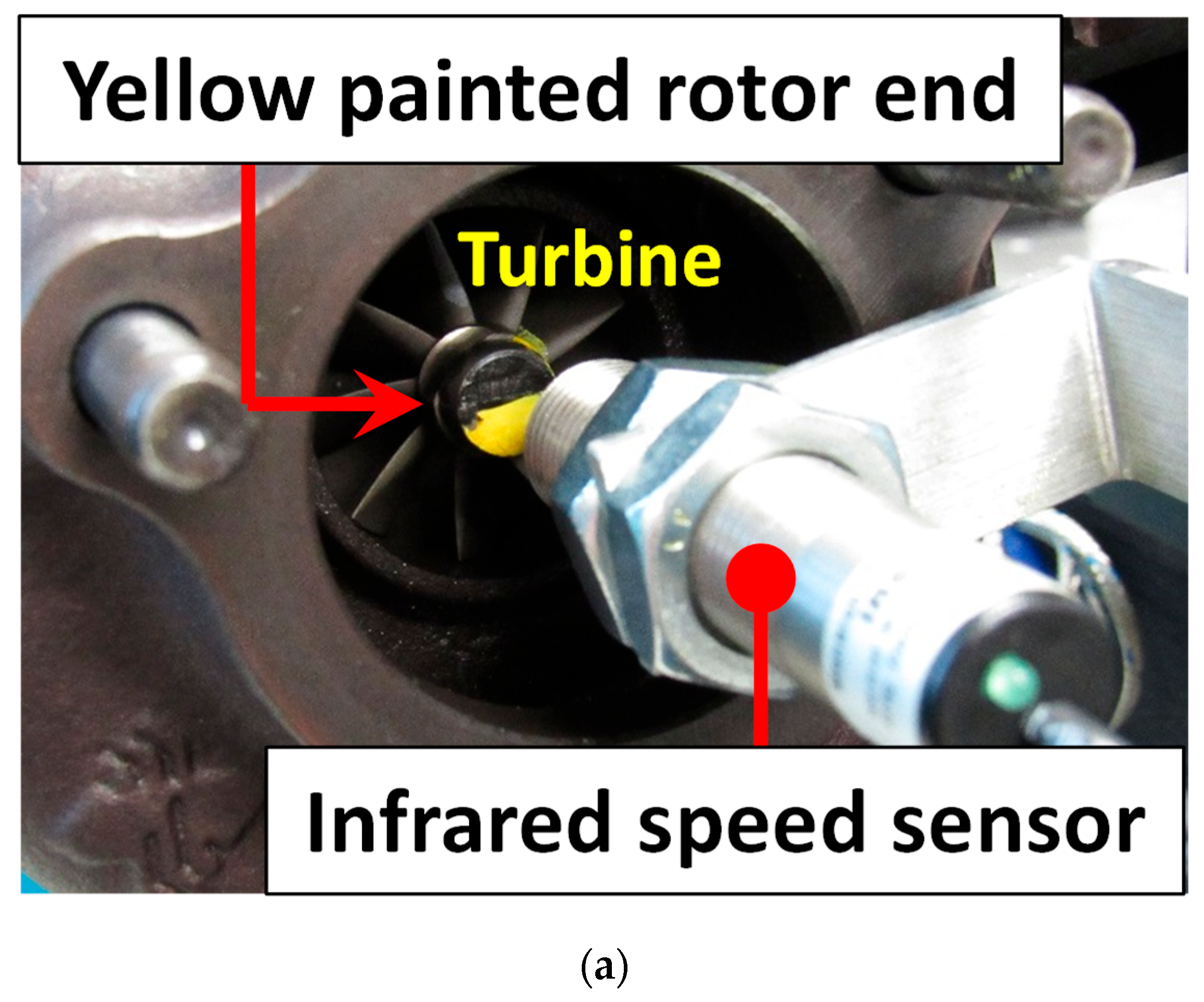
Figure 3 illustrates the two key sensors used for data acquisition. An IR speed sensor (
Figure 3a) measures rotor speed by detecting a reflective yellow-painted mark on the turbine wheel, generating one pulse per revolution. A triaxial accelerometer (
Figure 3b) is mounted directly on the bearing housing and measures vibrational acceleration in the vertical, axial, and horizontal directions.
Table 1 provides specifications of the two commercial test turbochargers. TC1, equipped with an FFRB, represents a small gasoline engine application (1.0–1.1 L), while TC2, using an SFRB, corresponds to a mid-sized diesel engine platform (2.0–2.2 L). Due to manufacturing constraints, internal disassembly was not permitted; therefore, bearing dimensions and clearances were estimated from manufacturer data and nominal design specifications. Notably, TC1 featured a smaller shaft diameter (6 mm) and shorter bearings than TC2 (7 mm shaft), allowing TC1 to reach higher rotor speeds (up to ~200 krpm) compared to TC2 (~150 krpm).
All analog signals were acquired using a commercial data acquisition (DAQ) system with a sampling rate of 76.8 kHz. Spectral data were processed using fast Fourier transforms (FFTs) with a frequency resolution of 4.688 Hz and a Hanning window to minimize spectral leakage. For thermal diagnostics, a calibrated IR camera was used to monitor surface temperatures of the bearing housing, oil inlet, and outlet lines. The IR imaging system offered high temporal resolution and enabled full-field thermal visualization. The standard uncertainty for vibration measured using an accelerometer was 0.58 m/s2. For temperature and the standard uncertainties obtained by the IR camera and thermocouples are 1.15 °C and 1.27 °C, respectively.
This experimental configuration enables simultaneous evaluation of the turbocharger’s vibrational and thermal response under varying oil supply conditions, replicating real-world transient effects while isolating rotor-bearing behavior from combustion-related phenomena.
3. Measurements of Bearing Housing Acceleration: Waterfall Plots
Waterfall plots of bearing housing acceleration provide a spectral overview of vibration behavior as a function of increasing rotor speed. These plots allow for the visualization of subsynchronous and synchronous frequency components, their evolution with speed, and the identification of jump phenomena and nonlinear dynamic transitions. The results reveal substantial differences between the FFRB and SFRB systems in both frequency content and amplitude growth.
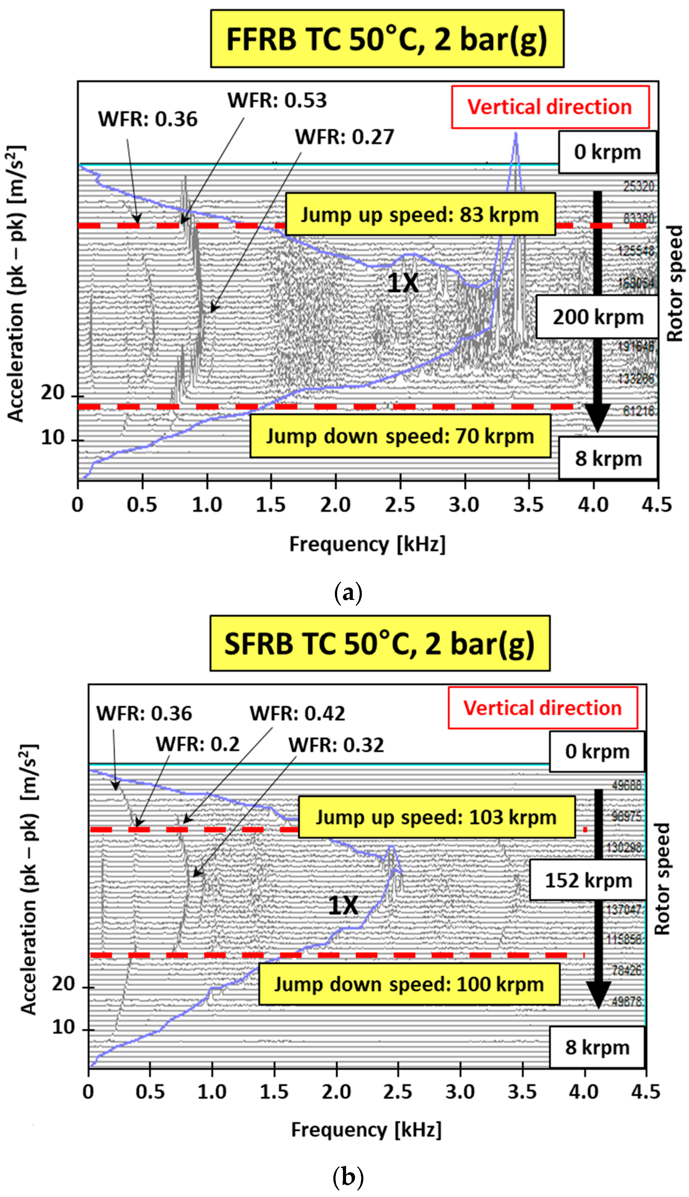
Figure 4 compares the acceleration spectra for both turbochargers under a common oil condition of 50 °C and 2 bar (g). The FFRB-supported unit exhibits stronger subsynchronous components, with multiple distinct frequency jumps occurring at approximately 70 krpm and 83 krpm. In contrast, the SFRB configuration shows similar phenomena but at higher speeds, around 100 and 103 krpm, and with a significantly reduced amplitude. This suggests that the squeeze film damping effect in the SFRB suppresses instability growth and delays the onset of critical motion.
Across the speed range, the FFRB-supported turbocharger also exhibited higher synchronous amplitudes, reflecting reduced damping and greater sensitivity to unbalance excitation. Whirl frequency ratios (WFRs) associated with subsynchronous components decreased from approximately 0.5 toward 0.3 as speed increased, consistent with the behavior of nonlinear whirl modes under increasing rotor momentum.
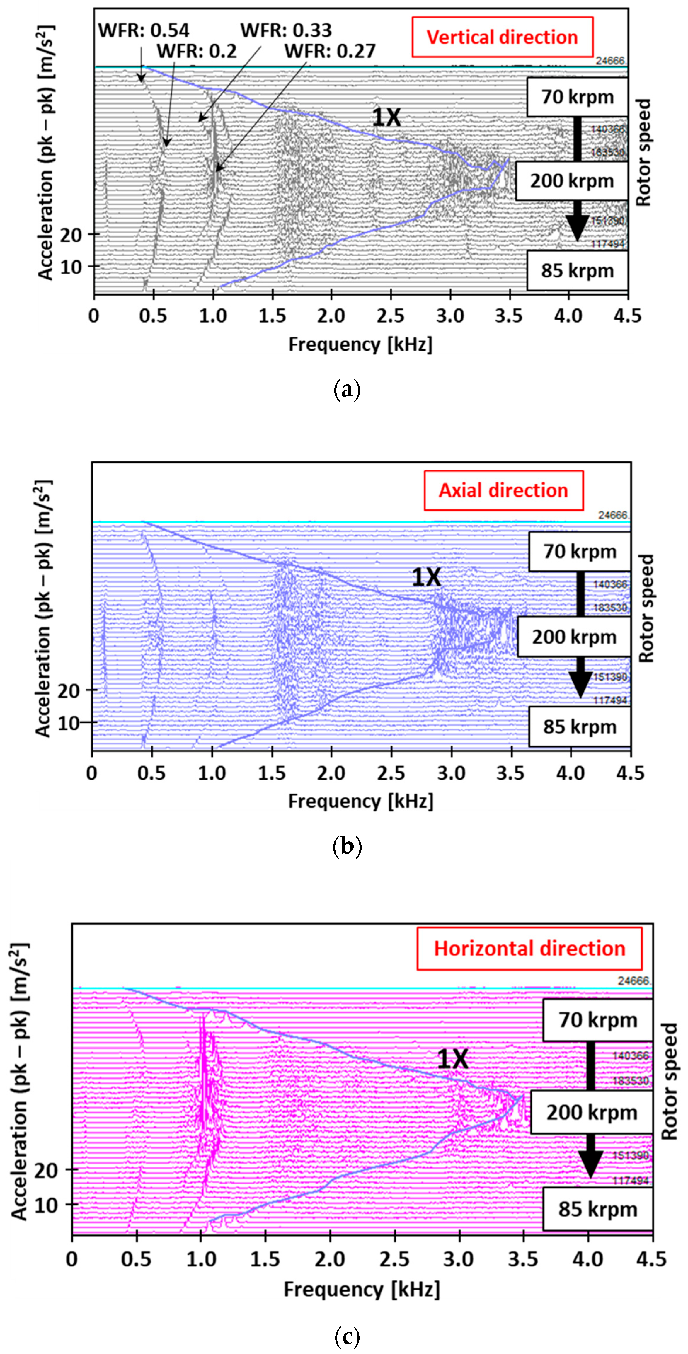
To investigate the influence of lubricant conditions on FFRB behavior,
Figure 5 and
Figure 6 present waterfall plots from three measurement directions (vertical, axial, horizontal) under contrasting oil supply settings.
Figure 5 reflects a low-temperature, high-pressure case (30 °C, 4 bar (g)), while
Figure 6 corresponds to high-temperature, low-pressure operation (70 °C, 2 bar (g)).
Under the high pressure in
Figure 5, the system demonstrated multiple subsynchronous frequency components prior to the jump, including visible harmonics at twice the base frequency. Following the jump, the spectral content consolidated into a dominant mode with a higher amplitude, which exceeded the synchronous component at top speed. This indicates that while high-pressure oil can postpone instability onset, it also permits substantial energy accumulation once instability occurs.
In contrast, the high-temperature case in
Figure 6 shows a relatively simpler spectral profile. The jump occurred earlier, near 60 krpm, and the synchronous component remained dominant throughout the speed range. The critical speed appeared near 150 krpm, though without pronounced resonance peaks. Post-jump, subsynchronous components grew moderately but remained lower in amplitude compared to the cooler oil case.
Directional variations are also evident. In both cases, the vertical and axial directions tended to show stronger subsynchronous activity than the horizontal direction. At top speed, the whirl frequency ratios across all cases tended to converge toward approximately 0.27, regardless of the operating condition.
These results affirm that oil supply conditions significantly impact the onset and severity of nonlinear vibration behavior. Lower oil temperatures and higher pressures increase fluid film stiffness, improving stability margins but amplifying post-jump responses. SFRBs, by comparison, exhibit a flatter vibrational response with delayed and less severe subsynchronous activity, validating the damping effectiveness of their constrained-ring architecture.
4. Measurements of Bearing Housing Acceleration: Bode Plots
To complement the spectral overview provided by the waterfall plots, Bode plots were constructed to quantify vibration amplitude trends as a function of rotor speed. These plots enable the tracking of both synchronous and subsynchronous vibration magnitudes and provide insight into jump phenomena, amplitude growth rates, and the influence of lubricant conditions. The plots shown in
Figure 7,
Figure 8,
Figure 9 and
Figure 10 are based on accelerometer data from the vertical direction and filtered using order-tracking techniques.
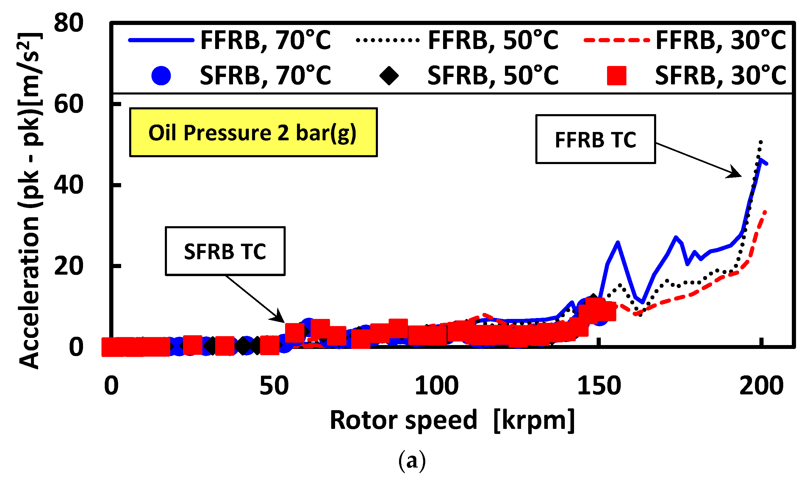
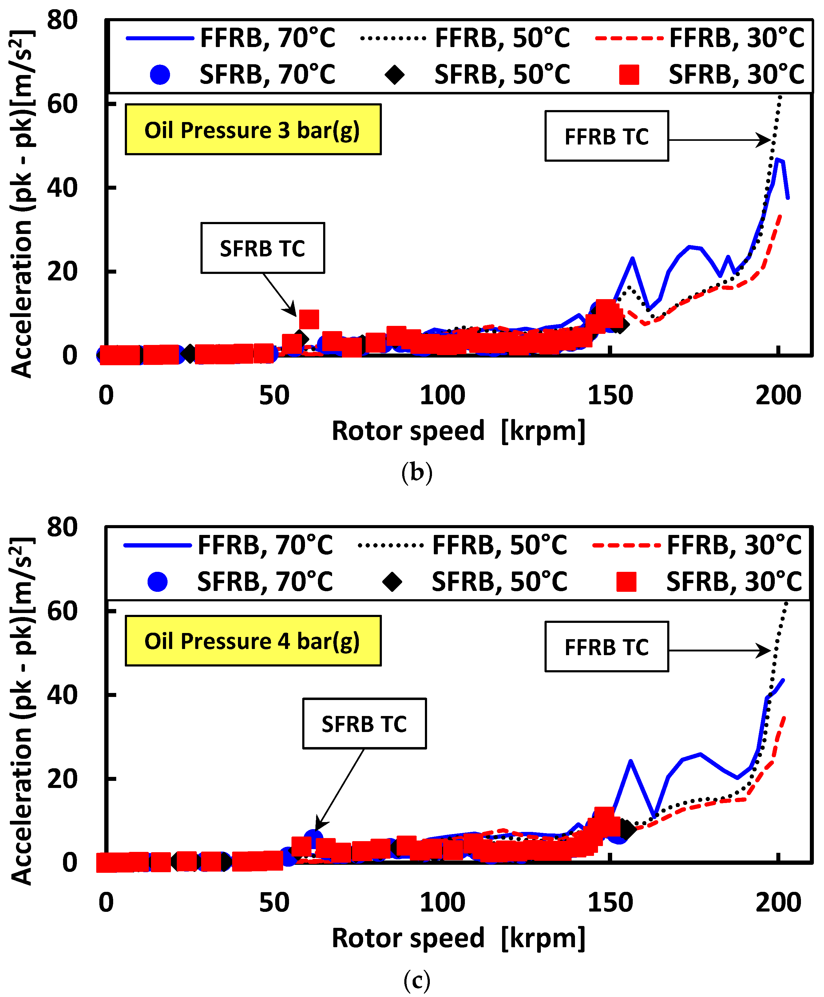
Figure 7 presents synchronous acceleration amplitudes for both FFRB- and SFRB-supported turbochargers under a fixed oil temperature of 30 °C and three different oil pressures: 2 bar (g), 3 bar (g), and 4 bar (g). Up to approximately 150 krpm, both systems showed relatively low and stable synchronous responses. Beyond this speed, the FFRB system exhibited a rapid increase in amplitude, particularly at the lowest pressure, indicating proximity to a resonance or loss of dynamic stiffness. In contrast, the SFRB system maintained a smoother and lower synchronous response across the entire speed range, with minimal influence from oil pressure.
Figure 8 illustrates the sum of subsynchronous components under the same test conditions. In the FFRB system, subsynchronous amplitudes rose sharply above 70 krpm and exhibited a distinct jump associated with nonlinear instability. This jump was particularly prominent at lower pressures. The SFRB system, on the other hand, exhibited a more gradual and linear increase in subsynchronous response, with no clear jump and much lower peak amplitudes. This difference underscores the stabilizing influence of the SFRB architecture.
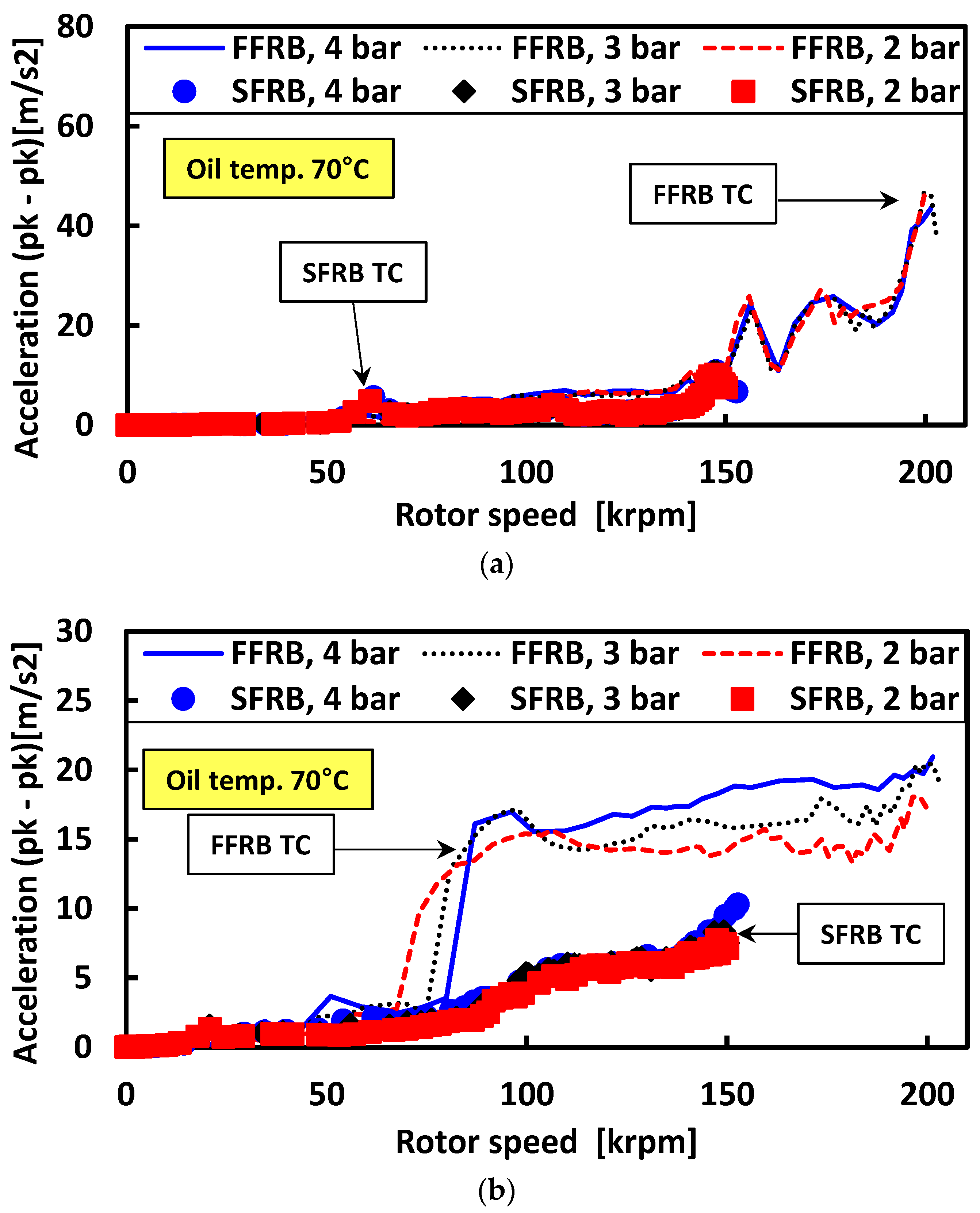
Figure 9 further examines the impact of oil pressure on both synchronous and subsynchronous amplitudes at a fixed oil temperature of 70 °C. For the FFRB turbocharger, increasing pressure led to a noticeable delay in the onset of subsynchronous growth and reduced post-jump amplitudes. The synchronous response, however, remained relatively unaffected by pressure. The SFRB results showed little variation with pressure, reaffirming the robustness of this configuration to changes in lubrication conditions.
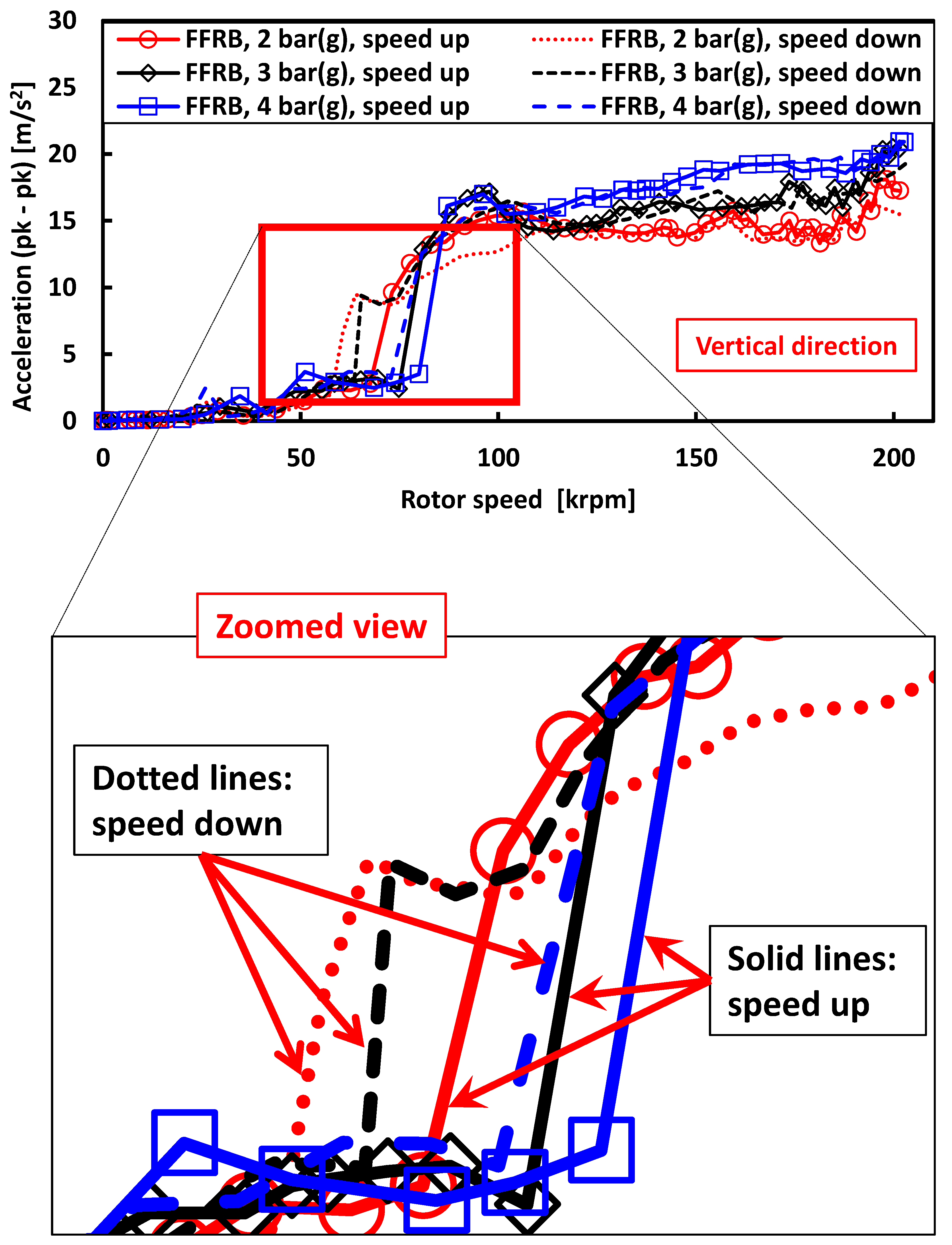
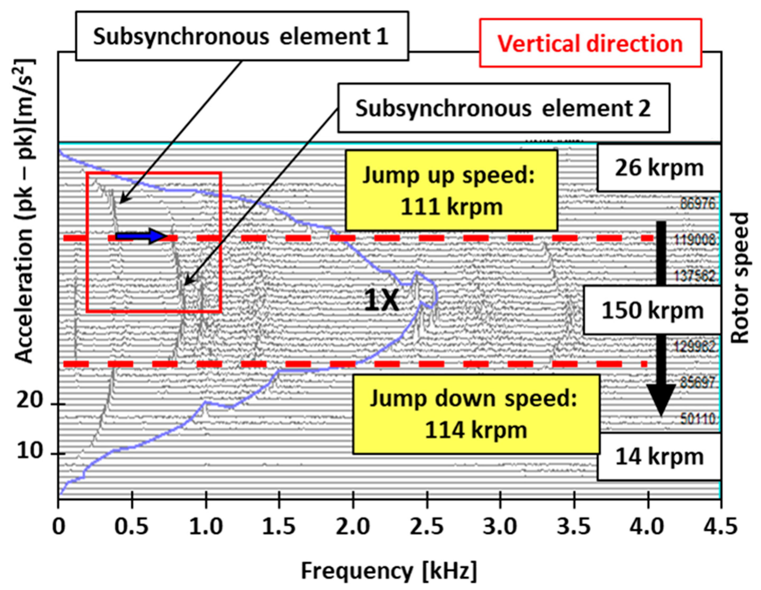
Figure 10 investigates hysteresis effects in the FFRB turbocharger at 70 °C by comparing acceleration and deceleration runs. A clear hysteresis loop is observed in the subsynchronous amplitude profile, with the frequency jump occurring at a higher speed during acceleration (~111.5 krpm) than during deceleration (~103 krpm). This behavior indicates nonlinear memory effects and energy storage in the system, a characteristic absent in the SFRB results.
Bode plot analysis reveals that the FFRB system is highly sensitive to lubricant conditions and prone to amplitude jumps and hysteresis behavior. In contrast, the SFRB-supported turbocharger maintains consistent performance with smaller vibration amplitudes, stable trends, and no observable hysteresis, making it the more robust and predictable solution under high-speed operation.
5. Measurements of Jump Speed and Hysteresis Characteristics
To further quantify the onset of instability in both bearing systems, jump speeds were extracted from the Bode plots of subsynchronous vibration amplitudes. These jump speeds indicate the rotor speed at which a sudden increase in subsynchronous activity occurs, marking the transition to a nonlinear or unstable vibrational regime. The presence or absence of hysteresis in these transitions also provides insight into the dynamic stiffness and damping characteristics of the bearing systems.
Figure 11,
Figure 12,
Figure 13 and
Figure 14 summarize these findings.
Figure 11 shows the jump speeds of both the FFRB- and SFRB-supported turbochargers as a function of oil pressure at a constant oil temperature of 70 °C. In the FFRB configuration, increasing oil pressure from 2 bar (g) to 4 bar (g) resulted in a marked increase in jump speed—from approximately 72 krpm to 85 krpm. This trend is attributed to enhanced film stiffness and damping at higher pressures. By contrast, the SFRB turbocharger displayed only a modest increase in jump speed with pressure, remaining in a relatively stable range around 98–100 krpm. This suggests that the SFRB’s damping mechanism is inherently less sensitive to changes in lubrication pressure.
Figure 12 illustrates the effect of oil temperature on jump speed at a fixed pressure of 2 bar (g). As oil temperature increased from 30 °C to 70 °C, the jump speed for the FFRB-supported turbocharger decreased from approximately 83 krpm to 61 krpm, reflecting the reduced viscosity and lower film stiffness at elevated temperatures. Conversely, the SFRB-supported unit showed minimal change in jump speed over the same temperature range, again indicating its robust damping behavior.
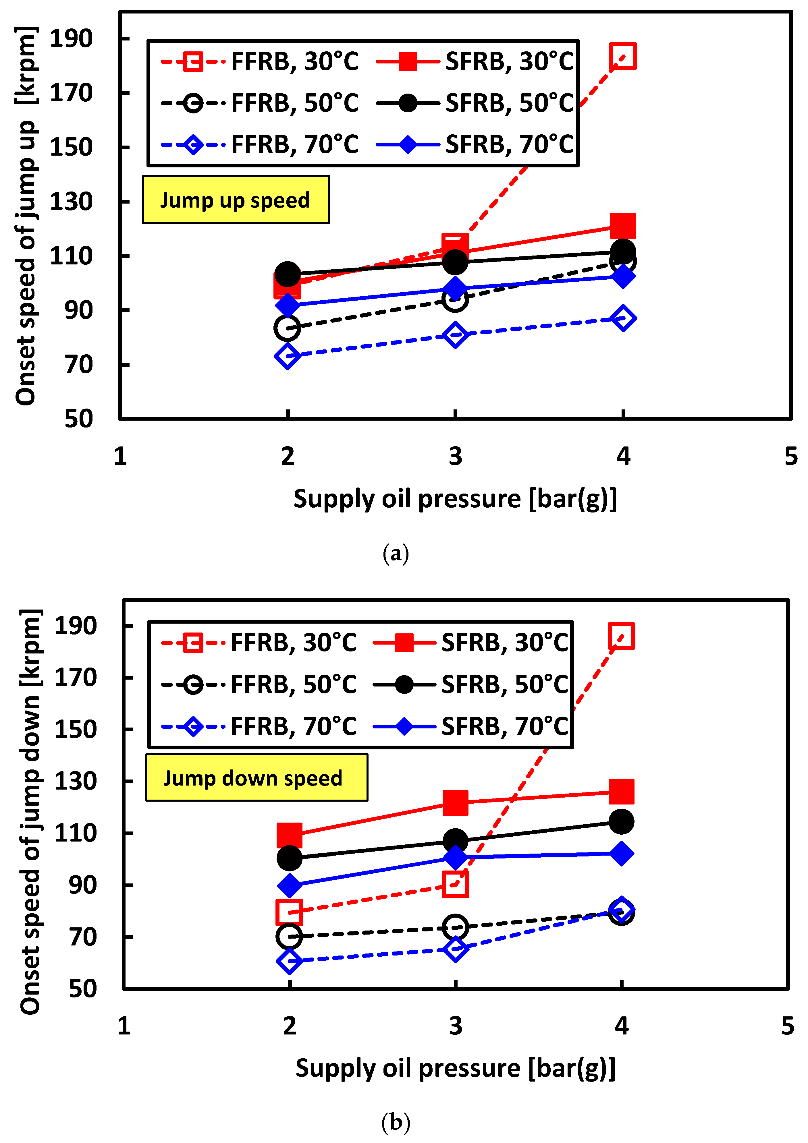
Figure 13 compares the jump-up and jump-down speeds for both turbochargers at 30 °C across varying pressures. The FFRB system exhibited significant hysteresis: the jump-up speed rose with increasing pressure, while the jump-down speed remained notably lower. This separation is indicative of nonlinear stiffness characteristics and energy dissipation delays. In contrast, the SFRB-supported turbocharger displayed tightly grouped jump-up and jump-down speeds with minimal hysteresis, supporting the assertion of a more linear and predictable dynamic response.
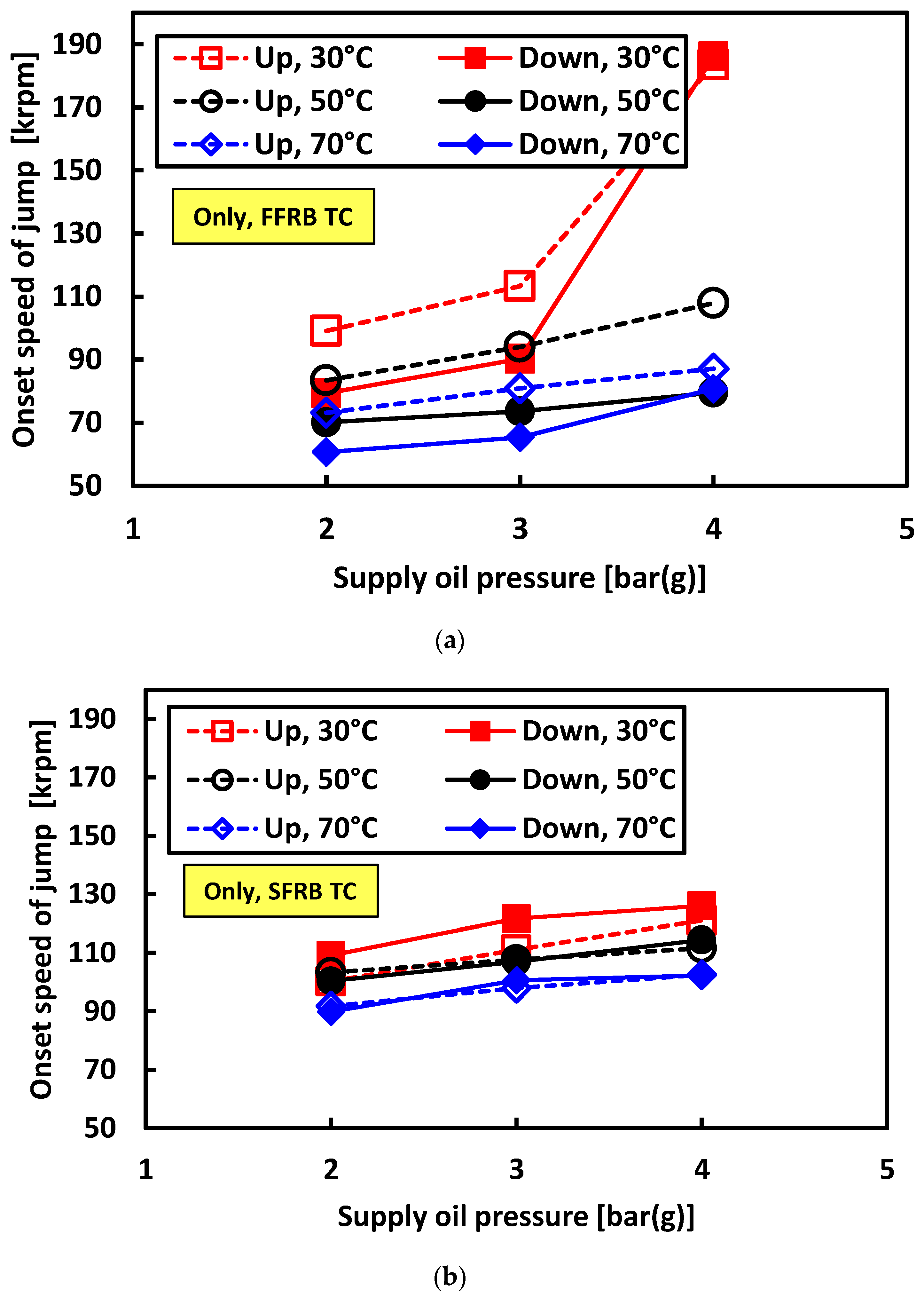
Figure 14 aggregates jump speed data across all tested oil pressures and temperatures. The FFRB turbocharger displayed a wide spread of jump speeds, confirming its high sensitivity to operating conditions. As
Figure 14a shows, the jump speed increased sharply when the supply pressure was 4 bar (g) and the supply temperature was 30 °C. Both lower lubricant viscosity and higher supply pressure tend to delay this jump speed. The SFRB turbocharger, however, maintains a narrow band of jump speeds across the entire test matrix. This clear difference further underscores the SFRB’s insensitivity to changes in oil properties and its superior rotordynamic stability.
The observed hysteresis behavior in the FFRB configuration, consistent with the findings in
Figure 10, suggests a strong dependence on the operating trajectory. Such characteristics may lead to persistent vibration even as speed is reduced, complicating control strategies in variable-speed applications. The SFRB system’s lack of hysteresis and reduced sensitivity to pressure and temperature shifts make it a more robust solution for consistent high-speed operation.
6. Measurements of Thermal Response: IR Imaging and Oil Outlet Temperature
In addition to vibrational analysis, thermal behavior was assessed using IR imaging and oil outlet temperature measurements. These diagnostics offered critical insight into frictional power loss, energy dissipation, and the relative thermal efficiency of the bearing systems under high-speed operation.
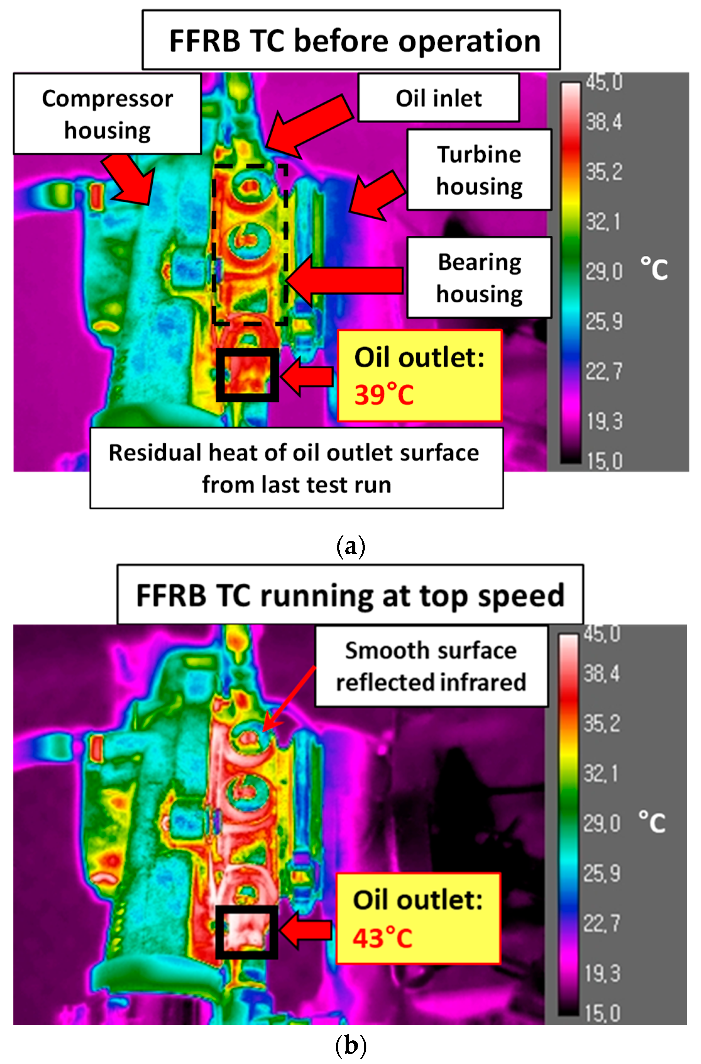
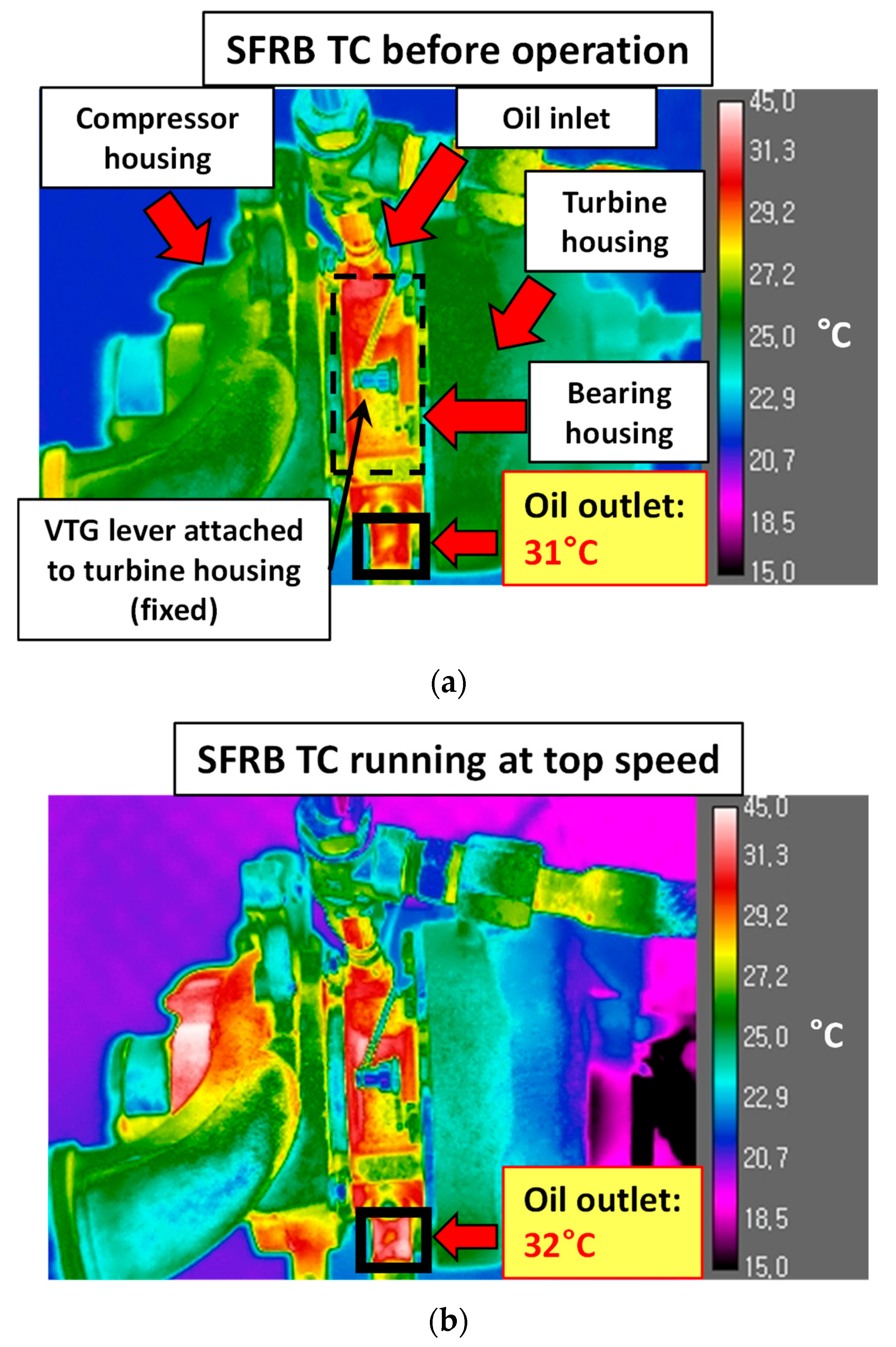
Figure 15 and
Figure 16 present the IR thermal images of the FFRB- and SFRB-supported turbochargers, respectively, under steady-state operation with an oil inlet temperature of 30 °C and a supply pressure of 2 bar (g). In the FFRB configuration (
Figure 15), a noticeable increase in temperature was observed at the bearing housing—particularly near the turbine-side journal bearing and the oil outlet region. The oil outlet temperature rose approximately 4 °C above the inlet, indicating significant internal heat generation. In contrast, the SFRB turbocharger (
Figure 16) showed a more uniform and subdued thermal profile, with only a 1 °C temperature increase. The reduction in thermal rise implies improved energy dissipation and less frictional heating, attributed to the constrained-ring design and enhanced damping performance of the SFRB.
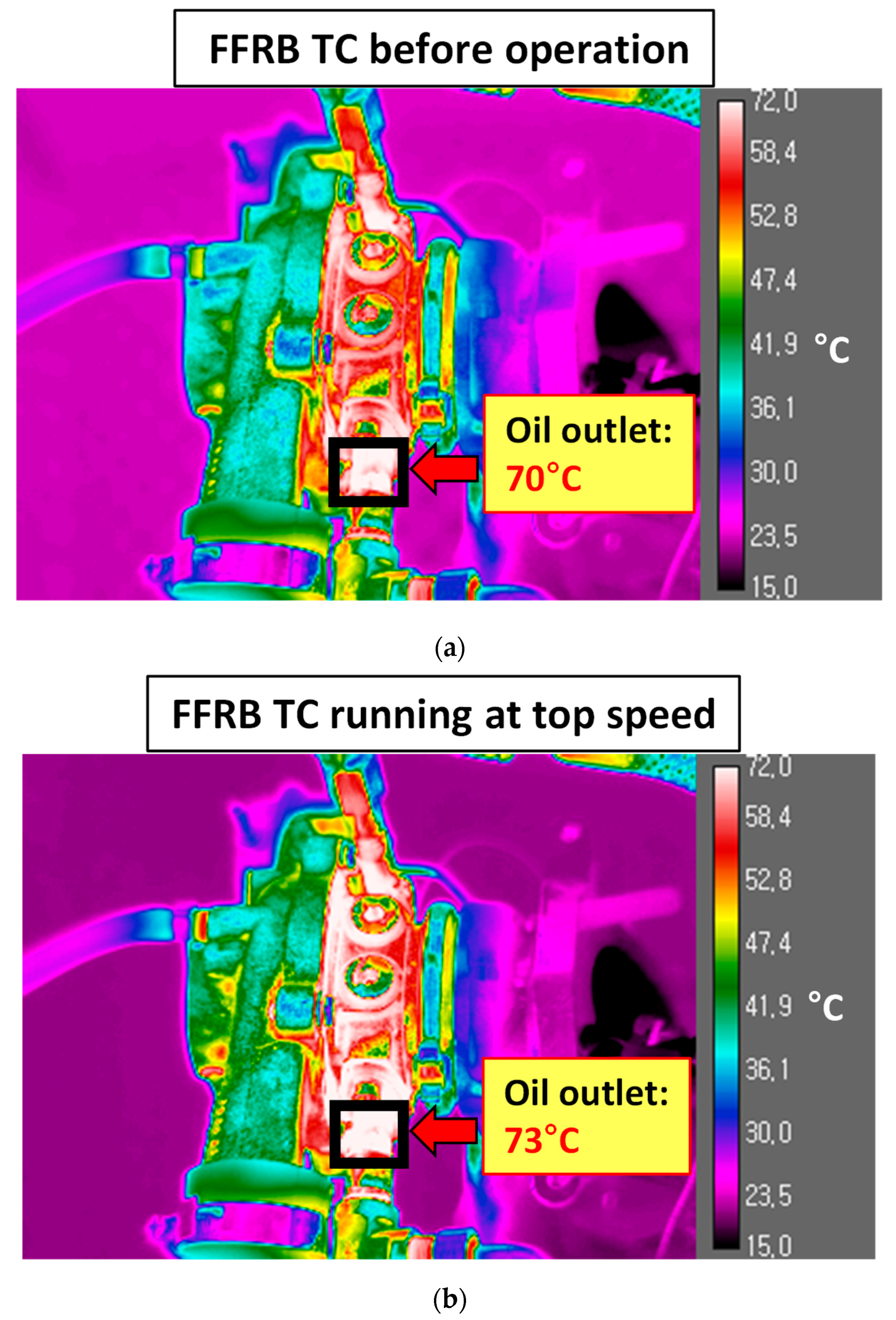
At elevated oil inlet temperatures of 70 °C (
Figure 17 and
Figure 18), the thermal contrast between the inlet and outlet narrowed in both turbochargers. Nevertheless, the FFRB still exhibited a greater overall temperature gradient. These results indicate that although baseline thermal levels rise with oil temperature, the relative thermal loading difference between bearing configurations remains consistent.
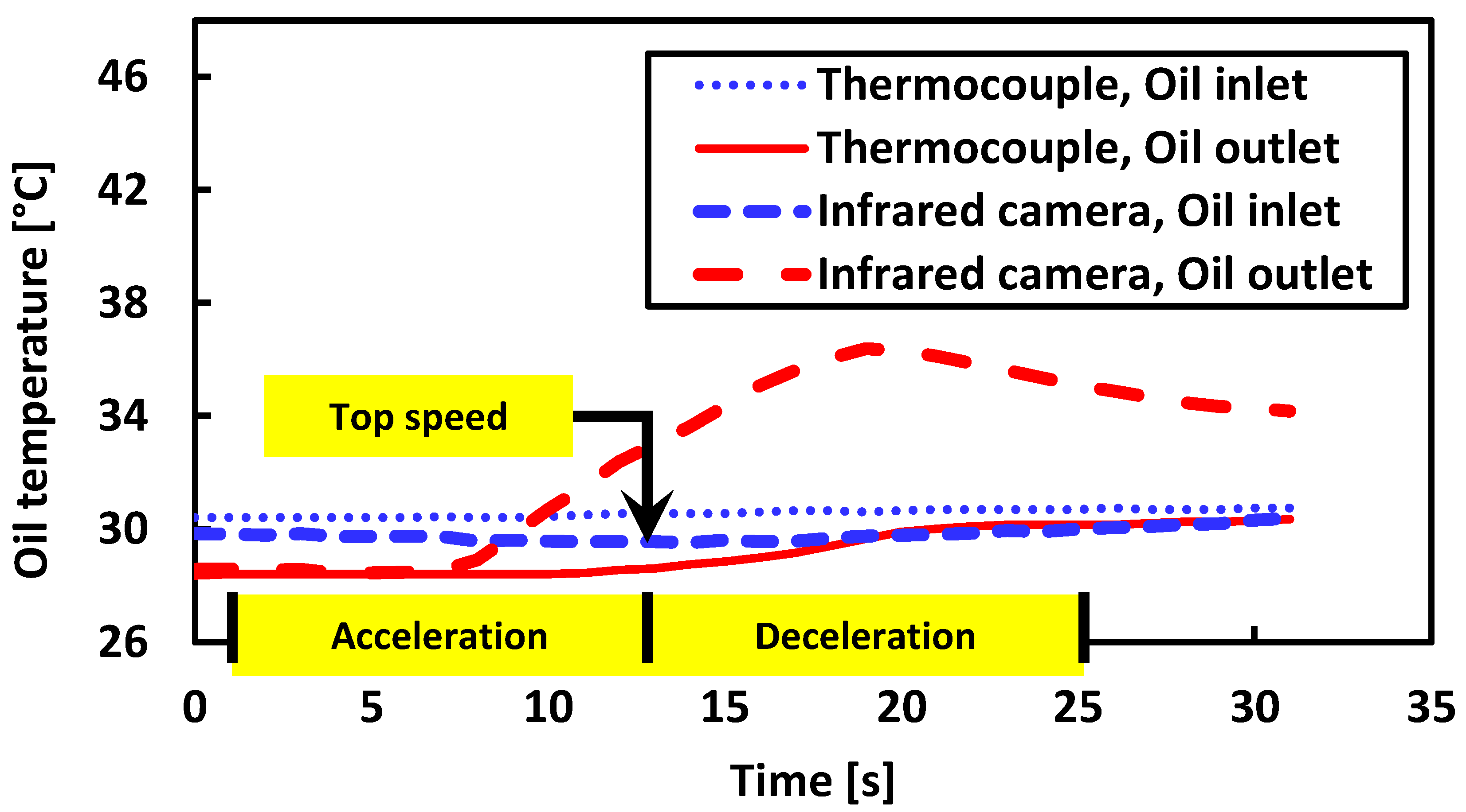
Figure 19 compares time-resolved oil outlet temperatures measured using both thermocouples and IR images in the FFRB turbocharger. The two methods show good agreement in steady-state conditions. However, during rapid acceleration events, the IR camera captures transient temperature changes more effectively, thanks to its faster response and non-contact measurement capability. This makes it particularly useful for diagnosing short-term thermal fluctuations and spatial heating trends.
The thermal results complement the vibrational analysis. The FFRB configuration, which exhibits stronger subsynchronous activity, also dissipates more energy through fluid shear and friction, leading to higher local and outlet temperatures. The SFRB configuration, on the other hand, generates less heat under equivalent test conditions, reinforcing its suitability for applications where thermal management is critical.
The IR images and outlet temperature data demonstrate that SFRB-supported turbochargers operate under reduced thermal loads. This finding, in tandem with the vibration suppression advantages, highlights the superior mechanical and thermal performance of the SFRB architecture in high-speed turbocharging environments.
7. Conclusions
This study presents a comprehensive experimental comparison of fully floating ring bearing (FFRB) and semi-floating ring bearing (SFRB) configurations in automotive turbochargers, with particular emphasis on rotordynamic stability and thermal behavior under high-speed operating conditions. Through a series of controlled tests using a cold air-driven rig, vibration and temperature responses were systematically evaluated across a range of oil supply pressures and temperatures. For the FFRB TC, the jump speed of the subsynchronous vibrations varied from 61 krpm to 186 krpm depending on the lubricant supply conditions, resulting in a variation range of 125 krpm. In contrast, for the SFRB, the jump speed changed from 90 krpm to 126 krpm, with a narrower variation range of 36 krpm. Overall, the FFRB TC exhibited a jump speed variation due to lubricant supply conditions that was approximately 3.47 times larger than that of the SFRB TC.
The results clearly demonstrate that the FFRB-supported turbocharger exhibited a higher sensitivity to lubricant conditions. It was prone to early onset of subsynchronous instability, characterized by frequency jumps, increased vibration amplitudes, and a pronounced hysteresis loop between the acceleration and deceleration phases. In addition, thermal measurements showed a greater oil outlet temperature rise and more intense localized heating in the bearing housing of the FFRB unit, consistent with elevated frictional losses and dynamic instability.
In contrast, the SFRB-supported turbocharger consistently exhibited greater vibrational robustness, with lower amplitudes, delayed instability onset, and minimal hysteresis under varying oil conditions. Thermal analysis revealed a significantly lower heat generation, confirming the effectiveness of the SFRB design in suppressing dynamic excitation and enhancing thermal efficiency. These advantages stem from the SFRB’s constrained ring configuration, which enables the outer oil film to function as a squeeze film damper.
Taken together, the findings highlight the superior rotordynamic and thermal performance of the SFRB configuration. Its reduced sensitivity to oil pressure and temperature, lower vibrational excitation, and improved thermal stability position it as a more reliable and efficient solution for modern high-speed turbocharger applications. These results provide important guidance for bearing selection in advanced engine systems, particularly where durability, noise control, and thermal management are design priorities.
Future work may extend this study to include hot gas-driven operation in a gas stand facility, long-term durability assessments, and advanced modeling of squeeze film dynamics to further validate the performance benefits observed experimentally.


