Abstract
In industrial applications, rolling is commonly performed with lubrication to prevent undesirable modification of the sheet. Although it is well established that lubrication influences the microstructure and texture of deformed sheets through its effect on shear deformation, the underlying mechanisms remain insufficiently understood. In this study, we investigated how lubrication affects slip system activity during asymmetrical rolling, using viscoplastic modeling of BCC ferritic steel. Two conditions—lubricated and non-lubricated samples—were examined under asymmetrical rolling. Slip system activity was inferred from the rotation axes between pairs of orientations separated by low-angle grain boundaries, based on the assumption that such boundaries represent the simplest form of orientation change. A Viscoplastic Self-Consistent (VPSC) model employing an affine linearization scheme was used. This proved sufficient for evaluating slip system activity in BCC polycrystalline metals undergoing early-stage plastic deformation involving either plane strain or combined plane strain and shear. The results demonstrated that lubrication had a limiting effect by reducing the penetration of shear deformation through the thickness of the sample. Understanding this effect could enable the optimization of lubrication strategies—not only to minimize defects such as bending, but also to achieve microstructural characteristics favorable for industrial applications.
1. Introduction
An intriguing aspect of rolling deformation lies in its association with two mixed deformation modes: plane strain and shear strain [1]. It has been postulated that an asymmetrical rolling process allows the enhancement of shear strain, which is favorable for achieving grain refinement and an acceptable level of isotropy [2]. One of the most important parameters in asymmetrical rolling is lubrication. Lubrication is primarily employed to prevent sample bending [3] and to regulate thickness reduction during sheet rolling processes [4]. However, it has also been reported to influence the deformation mode so that the existence of lubricant on the sheet surface may convert surface shear deformation into plane strain, as evidenced by the emergence of shear texture at the expense of typical rolling texture [5]. A clearer conceptual understanding of the connection between lubrication and shear deformation is needed. Fortunately, in the case of AR, strain distribution is well-characterized. In AR, shear is dominant near the surface while plane strain is dominant at the center, making it easier to model the role of shear strain, even in 2D. Moreover, AR allows analysis of a wide range of strain levels through control of the processing parameters.
Plastic deformation has been frequently interpreted through the lens of slip system activity. Several studies have linked slip system activation to the development of anisotropy in crystalline materials [6,7]. One comprehensive review further explored which slip systems are most effective and fundamental in driving crystallographic rotation and kink formation [8]. Notably, Chen et al. [9] provided strong evidence that grain rotation under tensile deformation in face-centered cubic aluminum alloys can be predominantly explained by the activation of one or two specific slip systems. Lunt et al. incorporated slip system activity to correlate a complex condition of strain heterogeneity and strain patterns with the resulting microstructure and microtexture [10]. Building upon these findings, it is also essential to examine how complex deformation modes such as shear influence slip system activity, particularly in the context of asymmetrical rolling (AR) parameters such as lubrication.
Shear deformation is recognized as a complex mode of plastic deformation. To evaluate slip system activity under this condition, our experimental investigation was constrained by specific criteria. First, the sample was in the early stages of deformation, when the majority of grain boundaries are low-angle, thereby simplifying the analysis. Chen et al. [9] demonstrated that lattice rotation from low-angle boundaries can be interpreted through activation of the slip systems exhibiting the highest and second-highest Schmid factors. Similarly, Das et al. [11] identified low-strain amplitude regions as ideal for investigating dominant activity in a solo slip system. Therefore, our second criterion was to focus exclusively on regions where a solo slip system was active. Notably, one study utilizing dual-energy irradiation specifically examined the behavior of solo slip systems [12]. To complement our experimental observations, simulations were conducted using the Viscoplastic Self-Consistent (VPSC) model. Fergani et al. [13] applied the VPSC framework to study texture evolution in polycrystalline materials subjected to machining-induced deformation involving shear. Additionally, Wang et al. [14] integrated orientation imaging microscopy via EBSD with VPSC modeling to examine slip system activation during plastic deformation. In this study, a VPSC model was employed using a simple affine scheme, which was sufficient for the intended analysis. BCC ferritic metals were selected as the material system, as their texture development is primarily governed by the nature of the activated slip systems—making them well-suited for the present investigation focused on slip system activity.
This study aimed to elucidate the role of shear deformation in influencing slip system activity and texture evolution in BCC ferritic metals. To achieve this, our research was guided by the following objectives: (1) to simulate deformation under plane strain and plane + shear strain conditions using the VPSC model on grains with different orientation; (2) to identify and compare the active slip systems in lubricated and non-lubricated sample; and (3) to assess how lubrication as an asymmetrical rolling (AR) parameter may influence slip system selection. It was hypothesized that shear deformation would promote activation of slip systems differently compared to plane strain, resulting in a distinct process of texture evolution.
2. Materials and Methods
2.1. Material
The material used in this study was ferritic steel with the following chemical composition: Fe—0.0065 wt% C—0.157 wt% Mn—0.0243 wt% P—0.0004 wt% S—16.93 wt% Cr—0.128 wt% Ni—0.2322 wt% Ti, which provided extra titanium as stabilizer (by weight percentage). The initial sample, after homogenization of 950 °C for 1 h with furnace cooling, exhibited a microstructure with average grain size of ~70 µm and random texture. Yield strength and tensile strength were 275 MPa and 442 MPa, respectively.
2.2. Experimental Setup
Rolling was performed using two identical rolls, each with a diameter of 220 mm, as shown in Figure 1. The AR process was performed with a roll speed ratio of 1:2 for the lower (V1) and upper (V2) rolls, while the velocity of the lower roll was fixed at 5 RPM. Samples with dimensions of 10 cm:4 cm:3 mm were rolled for 10 passes with equal reductions of 3.5% per pass and a total reduction of 30%. To achieve this, the rolling gate size—defined as the distance between the upper and lower rolls—was adjusted for each rolling pass to achieve a controlled thickness reduction. In the first pass, the gate size was set to 2.895 mm (i.e., a reduction in thickness of 3.5% from the initial 3.000 mm). Subsequent passes continued with a 3.5% thickness reduction per pass; for example, the second pass used a gate size of 2.794 mm (a 3.5% reduction from 2.895 mm), and this process was repeated until the tenth pass which had a final gate size of 2.100 mm. After each rolling step, the thickness of the steel sheet was measured using a digital micrometer with a resolution of 0.001 mm to ensure precision.
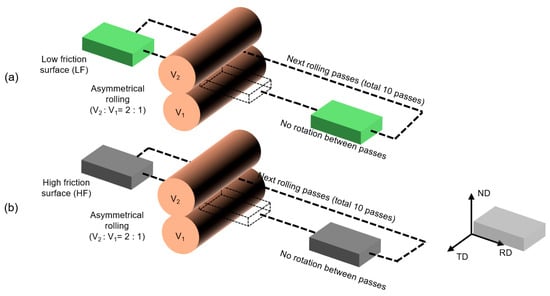
Figure 1.
Schematic of the asymmetrical rolling setup used for sample with (a) low-friction surface and (b) high-friction surface.
To establish two distinct conditions, non-lubricated and lubricated samples with graphite lubricant sprayed on their surfaces were made to generate samples with the high-friction roll-sheet condition and the low-friction roll-sheet condition, respectively. To see its effect on imposed shear strain, a dummy sample was made with indentation across the sample thickness and then rolled [15]. The shear was then calculated based on the following equation, as reported elsewhere [16]:
where εs is shear strain, r is thickness reduction in %, and is shear angle.
2.3. Characterization
To prepare the sample for EBSD observation, the sample surface was ground using SiC abrasive papers with grit sizes ranging from 180 to 1200 to obtain a smooth surface. Subsequently, polishing was carried out using a cloth and diamond suspensions of 1 µm and 0.25 µm to achieve a mirror-like finish. Final polishing was performed with colloidal silica (0.05 µm) to achieve a chemo-mechanical polish which combined mechanical polishing with etching.
The microstructure and the crystallographic texture of the deformed sample were characterized using a field-emission scanning electron microscope (FE-SEM) equipped with an electron backscatter diffraction (EBSD) detector. A step size of 2.5 microns, an accelerating voltage of 15 kV, an accelerating voltage of 41 μA, and a working distance of 20 mm were used. The EBSD data was compared with a ferrite phase database and further analyzed using the TSL-OIM software ver. 7.3.0 x64 [09-01-15]. For the inverse pole figure maps, two different boundaries, namely, low-angle boundaries (3 to 15° misorientation) and high-angle boundaries (15 to 65° misorientation), were used. The area of observation was limited to the center and upper surface because that asymmetrical rolling predominantly induces shear deformation on the upper surface.
2.4. Procedure for Active ‘Solo’ Slip System Determination
The suggested slip system method is shown in detail in Figure 2. Two rotation axes were obtained from experimental observations and from calculation using VPSC (pure red), as explained in detail in the figure. The first step was determination of an orientation pair (grain orientation vs grain substructure orientation) separated by low-angle boundaries. Grain orientation was selected based on its larger area inside the grain, compared with the grain substructure.
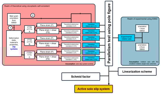
Figure 2.
Process diagram for determining the active solo slip systems of {110}<111>, {112}<111>, and {123}<111> based on theoretical predictions (under plane strain and plane + shear strain conditions) and experimental observations.
- The first step was identification of the theoretical rotation axis, in order to set up pole figures. To determine the theoretical rotation axis, grain orientation was inserted into the simulation parameter via the .tex file. VPSC was utilized using information for the orientation change that was obtained using electron backscatter diffraction (EBSD) in Bunge–Euler angle format (φ1, Φ, and φ2). One simulation was carried out for each case of a solo slip system.
- The second step was identification of the experimental rotation axis. To this end, two orientations (grain and grain substructure orientation) separated by low angle boundaries (LAB) were obtained using EBSD.
This study utilized the VPSC (version 7d) code written in the Fortran language developed by C.N. Tomé and R.A. Lebensohn (Los Alamos National Laboratory—Los Alamos, NM, USA) [17]. VPSC allows interconnection between rotation of individual crystals and crystallographically resolved mechanical responses on the slip system when subjected to external loading (in this study we incorporated asymmetrical rolling) [18]. In this study, the LIJ_HIST.DAT file was utilized to simulate rolling with the superimposed variable shear. Considering that the deformation occurs at an early stage, and that the rotation axes are derived from low-angle boundaries, each VPSC simulation includes only one slip system family as input. In the current study, we carried out separated simulations considering only the activity of the solo {110}<111>, {112}<111>, and {123}<111> slip systems. The initial critical resolved shear stress is assumed to be the same for all slip systems [19]. In polycrystalline aggregates, the local viscoplastic behavior of individual grains is characterized using a non-linear rate-sensitive constitutive equation.
Linearizing the equation above inside the domain of a grain gives the following:
Depending on the linearization assumption, (viscoplastic compliance) and (back-extrapolated) term of grain can be chosen differently.
Using affine,
Affine linearization was employed in this study, as it does not require commitment to either extreme (upper or lower bounds). Instead, it assumes that the response of the selected grains lies between the Taylor (upper) and Sachs (lower) bounds, offering a balanced approximation.
Crystal Option
In this study, a solo slip system was established in which the selected family was either , , or . In ferrite (BCC), 48 slip systems are equally likely to be active, namely, the 12 {110}<111>, 12 {112}<111>, and 24 {123}<111> systems [20,21]. The family members of each slip system are presented in Table 1.

Table 1.
List of the family members of {110}<111>, {112}<111>, and {123}<111> slip systems.
The strain rate sensitivity exponent n was set to be 20. An absence of hardening was assumed, and all slip systems were assigned the same initial CRSS of τ0 = 2 MPa. These, along with the slip system, will be incorporated into Equation (7). This study established that the {123}<111> glide systems contribute a considerable amount of shear which was formerly attributed exclusively to the {110}<111> and {112}<111> slip systems [22,23]. In the model, the activation of the {110}<111>, {112}<111>, and {123}<111> slip systems was considered using identical critical resolved shear stresses.
Most work was carried out was in accordance with the Schmid factor using complex deformation mode. The Schmid factor was used for two different reasons: (1) for confirming the Schmid behavior; and (2) for deciding which slip system was activated (slip system 1 or slip system 2 or slip system 3) in cases where two or three exhibited the same rotation axes.
During the asymmetrical rolling process, the applied stress tensor was the following:
where K is the proportion of the applied shear component. For symmetrical rolling, K = 0; in the case of asymmetrical rolling, K ranges between 0.1 and 0.3 (we used 0.2) [24]. The pair of orientation was based on the main grain orientation. Only grains with orientations close to {111}//ND and {001}//ND were investigated as main grain orientations (Figure 3) because these were predominantly found in rolled samples.
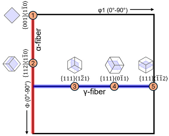
Figure 3.
Orientation distribution function (ODF) at φ2 = 45°, plotted with φ1 ranging from 0–90° and Φ from 0–90°, highlighting five grain orientations (labeled 1 to 5) selected for observation. These orientations are located along the α- and γ-fibers.
The orientations of {111}<-1-12> and {111}<1-21> were analyzed separately because these orientations are not equivalent to each other due to the lower symmetry in BCC, as compared to FCC. The grain orientations examined in this study are listed in Table 2.
Table 2.
Grain orientations selected for observation in this study.
3. Results
Figure 4a shows the inverse pole figure (IPF) maps obtained for initial, lubricated, and non-lubricated samples, with color following the orientation triangle. Two different regions were determined, namely, surface and center. Maps were superimposed with black-colored boundaries representing the boundaries, with misorientation ranging from 15° to 65°, so that grains could be separated from each other. The initial sample showed a microstructure of coarse equiaxed grains with random texture. After rolling deformation, most of the grains exhibited elongated grains along the rolling direction (RDs). To identify the five grain orientations (labeled 1 to 5) selected for observation, unique colored maps were generated (Figure 4b). It can be seen that ( and ) orientations exist both at the surface and at the center. From each of these grains, a pair of orientations (between grain orientation and grain substructure orientation) separated by low-angle boundaries (3 to 15° misorientation, 3 to 5° was used) was obtained.
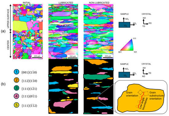
Figure 4.
(a) Inverse pole figures and (b) orientation maps with unique color coding based on five grain orientations (labeled 1 to 5) for both lubricated and non-lubricated samples. The analysis is limited to the microstructure at the top-surface and center regions. Also shown is a schematic illustration of a grain, indicating how grain orientation and grain substructure orientation are separated by low-angle grain boundaries.
We formed a set of visualizations of parallel tests using pole figures for all five orientations at the surface and center in the case of the lubricated sample. It is important to highlight that this is one representation, taken from among a number of observations (10 maps). Three pole figures were visualized when the center was the pole that ran parallel to the theoretical rotation axis (hkl // pole of the theoretical rotation axis of one slip system) for the three different slip systems ( , and ) using the theoretical parameter of affine linearization in Equations (4) and (5). Blue dots were used to represent the families of poles from the experimental rotation axis. When the poles from the theoretical rotation axis and the experimental rotation axis were parallel to each other, or the dots overlapped, this meant that the rotation axis between the theoretical and experimental were parallel to each other and the activity of that slip system was confirmed. A tolerance area with an error of around ~5 degrees was used.
Pole figures for the lubricated samples are presented in Figure 5a,b for the cases of surface and center, respectively. We categorized tendencies in slip system activity into three different categories. First, for and , the slip system was activated through the plane strain + shear (PS) mode of deformation at the surface and the plane strain (P) mode of deformation at the center, which is expected in general in the rolling process. These orientations predominantly activated the slip system in accordance with the Schmid factor rule (SF). Second, for , , and , the slip system was activated through only the plane strain (P) mode of deformation at both the surface and center, which is typical of the rolling process under lubrication where the shear effect is weakened. Third, , , and predominantly activated the , , and slip systems, respectively, in accordance with the Schmid factor rule (SF).
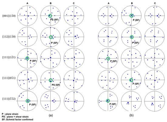
Figure 5.
Pole figures corresponding to the five selected grain orientations at the (a) surface and (b) center of the lubricated sample. Pole figures A, B, and C represent the {110}⟨111⟩, {112}⟨111⟩, and {123}⟨111⟩ slip systems, respectively. Activated single slip systems are highlighted with green circles, identified based on the parallelism test and Schmid factor analysis.
Pole figures of the non-lubricated samples are presented in Figure 6a,b for the cases of surface and center, respectively. The tendency in slip system activity was totally different to that in the lubricated sample. For instance, , showed a “switched” deformation mode where, instead of activating the slip system through shear at the surface, it activated it at the center. For , slip system activity was surprisingly high. Orientation was the only one that activated the slip system through plane strain both at the surface and center. However, a high number of slip systems were activated disregarding the Schmid factor rule, in this case in the activation of at the surface. Finally, and activated and , respectively, through plane + shear strain, following the Schmid factor rule.
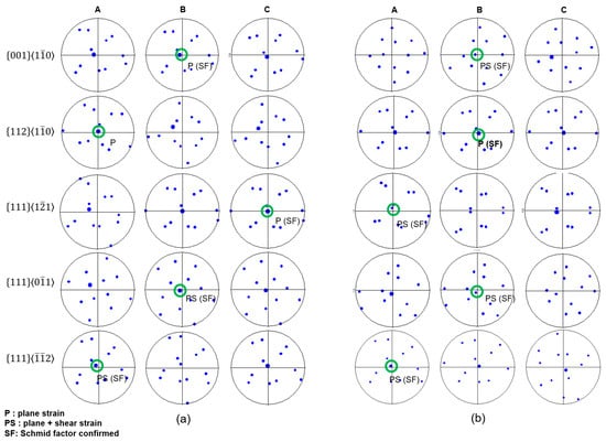
Figure 6.
Pole figures corresponding to the five selected grain orientations at the (a) surface and (b) center of the non-lubricated sample. Pole figures A, B, and C represent the {110}⟨111⟩, {112}⟨111⟩, and {123}⟨111⟩ slip systems, respectively. Activated single slip systems are highlighted with green circles, identified based on the parallelism test and Schmid factor analysis.
Figure 7 and Figure 8 show statistics for slip system activity in the lubricated and non-lubricated samples obtained using the method suggested in this study. The difference in numbers of active slip systems was considered significant in all cases where the dominant active slip system of its respective orientation assigned with letter a. Overall, the level of indexed slip system activity was higher in the case of lubricated sample as compared to the non-lubricated sample. In the lubricated sample, the level of indexed slip system activity was higher at the center.
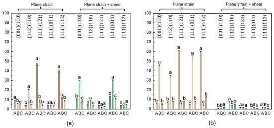
Figure 7.
Fractions of activated slip systems A, B, and C, corresponding to {110}⟨111⟩, {112}⟨111⟩, and {123}⟨111⟩, respectively, under plane strain and plane + shear strain conditions at the (a) surface and (b) center of the lubricated sample. Statistical analysis was performed using one-way ANOVA followed by Tukey’s post hoc test.
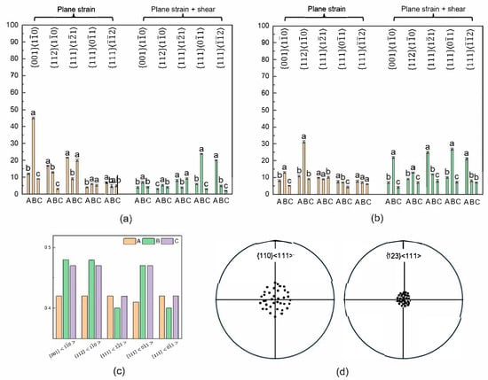
Figure 8.
Fractions of activated slip systems A, B, and C, corresponding to {110}⟨111⟩, {112}⟨111⟩, and {123}⟨111⟩, respectively, under plane strain and plane + shear strain conditions at the (a) surface and (b) center of the non-lubricated sample. (c) Distribution of Schmid factor in the case of plane strain. (d) Pole figure (showing only the center pole from 30 grains with orientation of ~{111}<11>) emphasizing {123}<111> slip system with closer theoretical rotation axis to the experimental rotation axis as compared to that of {110}<111> slip system. Statistical analysis was performed using one-way ANOVA followed by Tukey’s post hoc test.
As shown in Figure 7a,b, for the lubricated sample at the surface and center, respectively, orientation activated under plane + shear strain (30.2% ± 0.13) and under plane strain (46% ± 0.49) at the surface and center, respectively; orientation activated under plane strain (20.6% ± 0.48) and under plane strain (35% ± 0.49) at the surface and center, respectively; orientation activated under plane strain (47.8% ± 2.28) and under plane strain (61.4% ± 0.45) at the surface and center, respectively; orientation activated under plane+shear strain (30.5% ± 0.31) and under plane strain (55.5% ± 0.22) at the surface and center, respectively; orientation activated under plane strain (40.2% ± 1.57) and under plane strain (60.4% ± 0.22) at the surface and center, respectively.
As shown in Figure 8a,b, for the non-lubricated sample at the surface and center, respectively, orientation activated under plane strain (45.1% ± 0.50) and under plane + shear strain (21.9% ± 0.50) at the surface and center, respectively; orientation activated (16.7% ± 0.26) and (12.9% ± 0.46) under plane strain and under plane + shear strain (31.1% ± 0.74) at the surface and center, respectively; orientation activates under plane strain (21.6% ± 0.22) and under plane + shear strain (24.9% ± 0.6) at the surface and center, respectively. Notably, grains with a orientation exhibited a considerable level of slip system activity under plane strain conditions, with an average activity of 20% ± 0.7 at the surface—an occurrence considered rare. This slip system, along with , showed comparable Schmid factor values by incorporating Equation (8) (Figure 8c). To further support this observation, a specialized pole figure (Figure 8d) was generated, displaying only the central poles of 30 grains with the orientation. The pole figure demonstrated that the rotation axis associated with the slip system aligned more closely with the experimentally observed rotation axis than that of the system. It is important to note that all pole figures were constructed such that the central direction corresponded to the theoretically calculated rotation axis. As a result, the central axes of different grain groups varied depending on their orientations. Therefore, these particular pole figures should be interpreted in a qualitative rather than quantitative manner. It was found that orientation activated under plane + shear strain (23.8% ± 0.33) and under plane + shear strain (26.9% ± 0.62) at the surface and center, respectively; orientation activated under plane + shear strain (20% ± 0.33) and under plane + shear strain (21.1% ± 0.72) at the surface and center, respectively.
4. Discussion
The pronounced effect of shear deformation, usually indicated by the existence of shear texture near the surface region, is due to the heavy deformation applied during rolling without lubrication [25]. During rolling, the roll surface remains in direct contact with the metal surface. At the roll–sheet interface, the absence of lubrication and the presence of higher friction cause the surface layers in contact with the rolls to move relative to the inner material, resulting in surface shear deformation. This variation in deformation behavior leads to the development of a through-thickness texture gradient, which is more pronounced in non-lubricated samples, extending even to the sample center. The amount of shear strain can be calculated based on Equation (1). For lubricated and non-lubricated samples, the shear strains were ~0.1 (from φ = 15°) and ~0.4 (from φ = 45°), respectively. With the increase in strain amplitude, the activity of the single slip system decreases and that of the multiple slip system increases [11]. This is in agreement with the current study, in which the non-lubricated sample had a lower indexed active slip system, as compared to the lubricated sample, because of its higher strain which allowed more cases of a multiple slip system. Despite that, the impact of lubrication on shear deformation could still be seen by observing the active slip system and by determining whether its activation required the plane + shear strain mode of deformation. It is important to mention that in the non-lubricated sample, especially at the center, the level of slip system activity through plane + shear strain was higher than that in the lubricated sample. The results indicated that slip system activity at the sample center predominantly followed plane strain behavior in the lubricated condition. In contrast, the non-lubricated sample exhibited slip system activity characteristic of combined plane strain and shear deformation. In other words, the application of lubrication led to a lower contribution of shear deformation at the sample center, which is likely attributable to a shift in the dominant deformation mode from shear to plane strain. This may be considered as an indication that shear deformation penetration was hindered in the lubricated sample, as in the work reported by Kang et al. [5].
The orientation of grains played a more important role in determining slip system activity [23,26], despite reports suggesting that {110} planes are the principal slip planes in BCC crystals of iron, and {112} planes more generally, for the cases of twinning and anti-twinning [27]. Not only that, grains with different orientations may also show different lattice rotation effects when interacting with their differently oriented neighbors [28]. It was previously reported that {112} <111> slip systems mainly execute deformation of the texture components close to {001} <> and {112} <> [22]. In this study, , , and allowed activation of the slip system. In addition, {112}<111> and {110}<111> (multiple slip system) worked together around {112}<1-10>, resulting in difficulty in detection of solo slip system activity in that particular orientation using this method [22]. In this study, {112}<>, as compared to the other orientation, showed less solo slip system activity. For and , the most active slip system was . Slip system , using this method, could only be observed in grain with under the non-lubricated condition. The activation of {123}<111> in the non-lubricated sample might be associated with the very small difference of around ~0.42 between the Schmid factors of {110}<111> and {123}<111>. In addition, the non-lubricated condition also allowed slip system activity in disregard of the Schmid factor rule, which in this case was the activity of inside grain with orientation. Wijnen et al. suggested that stochastic effects dominate the behavior of ferrite crystals with dimensions in the order of a few micrometers, and that non-Schmid effects may not play a large role [29]. However, most of the cases followed the Schmid factor convention. This is in contrast with Marinelli et al., who suggested that the SF is not a decisive parameter for the development of plastic activity in the ferritic phase [30]. Thus, lubrication played a role in shear deformation in that increasing the shear strain (~0.4) by imposing the non-lubrication condition allowed shear deformation to penetrate the sample thickness toward the center of the sample. In addition, in the cases of lubricated and non-lubricated samples, with a different orientation, the slip system activity would also be different.
In this study, we were able to successfully identify the active slip systems by analyzing the grain rotation axes, even though the analysis was limited to cases involving solo/single slip system activity only. Vermeij et al. considered this as a necessary step before entering a more complex scenario [20]. Our results are consistent with findings obtained using other methods, indicating that the identification of slip system activity becomes increasingly difficult near the surface [31]. Although the current results revealed activation of the rare ‘solo’ slip system in the non-lubricated sample, the underlying mechanism remains unclear. Previous studies have reported that the involvement of shear deformation can lead to a high density of stacking faults, dislocations, and twin boundaries. These microstructural complexities significantly alter the dislocation arrangement, making it more challenging to accurately analyze the rotation axis and determine the corresponding slip system activity [32].
5. Conclusions
This study investigated the impact of lubrication on shear deformation in lubricated and non-lubricated samples subjected to asymmetrical rolling. Slip system activity for , , and was inferred by analyzing the rotation axes between orientations separated by low-angle grain boundaries. A Viscoplastic Self-Consistent (VPSC) model employing an affine linearization scheme was utilized to simulate deformation behavior. The results revealed distinct differences in slip system activity between lubricated and non-lubricated samples, clearly demonstrating that lubrication hinders the transmission of shear deformation through the sample thickness. Among the key findings, two grain orientations— and —were identified as favorable for shear propagation. Furthermore, asymmetrical rolling without lubrication enabled the activation of the additional slip system and exhibited signs of non-Schmid behavior, which may contribute to increased texture randomization.
The current fraction of indexed active slip systems is still considered small. Several key issues require further investigation to optimize the method to determine slip system activity and to further understand the role of the AR parameter.
- The selection of the linearization scheme can be modified according to the grain orientation. This is in accordance with the finding of the present study that only grain with orientation allowed activation of the slip system.
- As well as the Schmid factor, the geometric compatibility of slip systems in neighboring grains also plays an important role in slip system activation [33]. By increasing the number of available slip systems, an increase in phenomenological accuracy is achieved with no loss of numerical precision [7].
Author Contributions
Conceptualization, J.-H.K. and Y.G.K.; methodology, I.P.W., S.F., W.B., J.-H.K. and Y.G.K.; software, I.P.W. and W.B.; validation, I.P.W., S.F., W.B., J.-H.K. and Y.G.K.; formal analysis, I.P.W. and S.F.; investigation, I.P.W. and S.F.; resources, I.P.W. and S.F.; data curation, I.P.W. and W.B.; writing—original draft preparation, I.P.W. and S.F.; writing—review and editing, I.P.W., S.F., J.-H.K. and Y.G.K.; visualization, J.-H.K. and Y.G.K.; supervision, J.-H.K. and Y.G.K.; project administration, J.-H.K. and Y.G.K.; funding acquisition, J.-H.K. and Y.G.K. All authors have read and agreed to the published version of the manuscript.
Funding
This research received no external funding.
Data Availability Statement
The data presented in this study are available on request from the corresponding author. The data are not publicly available due to their containing information that could compromise the privacy of research participants.
Conflicts of Interest
The authors declare no conflict of interest.
Nomenclature
| AR | Asymmetrical rolling |
| BCC | Body-centered cubic |
| EBSD | Electron backscatter diffraction |
| VPSC | Viscoplastic self-consistent |
| εij | Deviatoric strain rate |
| εij(r) | Deviatoric strain rate after linearizing inside the domain of grain (r) |
| εijo(r) | Back-extrapolated term of grain (r) |
| mij | Symmetric Schmid tensor |
| mijkl(r) | Viscoplastic compliance |
| σkl | Deviatoric stress |
| σkl(r) | Deviatoric stress after linearizing inside the domain of grain (r) |
| γs | Local shear rate on slip system S |
| τ | Threshold stress |
| W0ij(r) | Skew-symmetric rotation rate inside the domain of grain (r) |
| n | Normal of slip system |
| b | Burger vectors of slip system |
References
- Segal, V. Review: Modes and Processes of Severe Plastic Deformation (SPD). Materials 2018, 11, 1175. [Google Scholar] [CrossRef] [PubMed]
- Gao, H.; Ramalingam, S.C.; Barber, G.C.; Chen, G. Analysis of Asymmetrical Cold Rolling with Varying Coefficients of Friction. J. Mater. Process. Technol. 2002, 124, 178–182. [Google Scholar] [CrossRef]
- Su, H.; Hou, L.; Tian, Q.; Wang, Y.; Zhuang, L. Understanding the Bending Behavior and Through-Thickness Strain Distribution during Asymmetrical Rolling of High-Strength Aluminium Alloy Plates. J. Mater. Res. Technol. 2023, 22, 1462–1475. [Google Scholar] [CrossRef]
- Thorp, J.M. Mechanism of Lubrication in Cold Rolling. Proc. Inst. Mech. Eng. 1961, 175, 593–603. [Google Scholar] [CrossRef]
- Kang, C.G.; Kang, H.G.; Kim, H.C.; Huh, M.Y.; Suk, H.G. Formation of Shear Texture Components during Hot Rolling of AA 1050. J. Mater. Process. Technol. 2007, 187–188, 542–545. [Google Scholar] [CrossRef]
- Orozco-Caballero, A.; Li, F.; Esqué-de los Ojos, D.; Atkinson, M.D.; Quinta da Fonseca, J. On the Ductility of Alpha Titanium: The Effect of Temperature and Deformation Mode. Acta Mater. 2018, 149, 1–10. [Google Scholar] [CrossRef]
- Hamelin, C.J.; Diak, B.J.; Pilkey, A.K. Multiscale Modelling of the Induced Plastic Anisotropy in Bcc Metals. Int. J. Plast. 2011, 27, 1185–1202. [Google Scholar] [CrossRef]
- Weinberger, C.R.; Boyce, B.L.; Battaile, C.C. Slip Planes in Bcc Transition Metals. Int. Mater. Rev. 2013, 58, 296–314. [Google Scholar] [CrossRef]
- Chen, P.; Mao, S.C.; Liu, Y.; Wang, F.; Zhang, Y.F.; Zhang, Z.; Han, X.D. In-Situ EBSD Study of the Active Slip Systems and Lattice Rotation Behavior of Surface Grains in Aluminum Alloy during Tensile Deformation. Mater. Sci. Eng. A 2013, 580, 114–124. [Google Scholar] [CrossRef]
- Lunt, D.; Thomas, R.; Atkinson, M.D.; Smith, A.; Sandala, R.; da Fonseca, J.Q.; Preuss, M. Understanding the Role of Local Texture Variation on Slip Activity in a Two-Phase Titanium Alloy. Acta Mater. 2021, 216, 117111. [Google Scholar] [CrossRef]
- Das, A. Slip System Activity during Cyclic Plasticity. Metall. Mater. Trans. A Phys. Metall. Mater. Sci. 2014, 45, 2927–2930. [Google Scholar] [CrossRef]
- Mengiste, E.; Piedmont, D.; Messner, M.C.; Li, M.; Stubbins, J.; Park, J.S.; Zhang, X.; Kasemer, M. Effect of Irradiation-Induced Strength Anisotropy on the Reorientation Trajectories and Fragmentation Behavior of Grains in BCC Polycrystals under Tensile Loading. Acta Mater. 2024, 263, 119503. [Google Scholar] [CrossRef]
- Fergani, O.; Tabei, A.; Garmestani, H.; Liang, S.Y. Prediction of Polycrystalline Materials Texture Evolution in Machining via Viscoplastic Self-Consistent Modeling. J. Manuf. Process. 2014, 16, 543–550. [Google Scholar] [CrossRef]
- Wang, Q.; Shankar, R.M.; Liu, Z. Visco-Plastic Self-Consistent Modeling of Crystallographic Texture Evolution Related to Slip Systems Activated during Machining Ti-6AL-4V. J. Alloys Compd. 2021, 853, 157336. [Google Scholar] [CrossRef]
- Kamikawa, N.; Sakai, T.; Tsuji, N. Effect of Redundant Shear Strain on Microstructure and Texture Evolution during Accumulative Roll-Bonding in Ultralow Carbon IF Steel. Acta Mater. 2007, 55, 5873–5888. [Google Scholar] [CrossRef]
- Park, J.H.; Hamad, K.; Widiantara, I.P.; Ko, Y.G. Strain and Crystallographic Texture Evaluation of Interstitial Free Steel Cold Deformed by Differential Speed Rolling. Mater. Lett. 2015, 147, 38–41. [Google Scholar] [CrossRef]
- Lebensohn, R.A.; Tomé, C.N. A Self-Consistent Anisotropic Approach for the Simulation of Plastic Deformation and Texture Development of Polycrystals: Application to Zirconium Alloys. Acta Metall. Mater. 1993, 41, 2611–2624. [Google Scholar] [CrossRef]
- Ochoa-Avendaño, J.; Sedighiani, K.; Galan-Lopez, J.; Bos, C.; Kestens, L.A.I. Comparative Analysis of Crystal Plasticity Models in Predicting Deformation Texture in IF-Steel. J. Mater. Res. Technol. 2024, 31, 3844–3859. [Google Scholar] [CrossRef]
- Tamimi, S.; Gracio, J.J.; Lopes, A.B.; Ahzi, S.; Barlat, F. Asymmetric Rolling of Interstitial Free Steel Sheets: Microstructural Evolution and Mechanical Properties. J. Manuf. Process. 2018, 31, 583–592. [Google Scholar] [CrossRef]
- Vermeij, T.; Peerlings, R.H.J.; Geers, M.G.D.; Hoefnagels, J.P.M. Automated Identification of Slip System Activity Fields from Digital Image Correlation Data. Acta Mater. 2023, 243, 118502. [Google Scholar] [CrossRef]
- Tian, C.; Ponge, D.; Christiansen, L.; Kirchlechner, C. On the Mechanical Heterogeneity in Dual Phase Steel Grades: Activation of Slip Systems and Deformation of Martensite in DP800. Acta Mater. 2020, 183, 274–284. [Google Scholar] [CrossRef]
- Raabe, D. Contribution of {123} <111> Slip Systems to Deformation of b.c.c. Metals. Phys. Status Solidi 1995, 149, 575–581. [Google Scholar] [CrossRef]
- Raabe, D. Simulation of Rolling Textures of Bcc Metals under Consideration of Grain Interactions and {110}, {112} and {123} Slip Planes. Mater. Sci. Eng. A 1995, 197, 31–37. [Google Scholar] [CrossRef]
- Uniwersał, A.; Wroński, M.; Wróbel, M.; Wierzbanowski, K.; Baczmański, A. Texture Effects Due to Asymmetric Rolling of Polycrystalline Copper. Acta Mater. 2017, 139, 30–38. [Google Scholar] [CrossRef]
- Bruna, R.G. Effects of Hot and Warm Rolling on Microstructure, Texture and Properties of Low Carbon Steel. Rem Rev. Esc. Minas 2011, 64, 57–62. [Google Scholar] [CrossRef]
- Liu, M.; Liu, Y.; Li, H. Deformation Mechanism of Ferrite in a Low Carbon Al-Killed Steel: Slip Behavior, Grain Boundary Evolution and GND Development. Mater. Sci. Eng. A 2022, 842, 143093. [Google Scholar] [CrossRef]
- Franciosi, P.; Le, L.T.; Monnet, G.; Kahloun, C.; Chavanne, M.H. Investigation of Slip System Activity in Iron at Room Temperature by SEM and AFM In-Situ Tensile and Compression Tests of Iron Single Crystals. Int. J. Plast. 2015, 65, 226–249. [Google Scholar] [CrossRef]
- Wang, R.; Lu, C.; Tieu, K.A.; Gazder, A.A. Slip System Activity and Lattice Rotation in Polycrystalline Copper during Uniaxial Tension. J. Mater. Res. Technol. 2022, 18, 508–519. [Google Scholar] [CrossRef]
- Wijnen, J.; Hoefnagels, J.P.M.; Geers, M.G.D.; Peerlings, R.H.J. Discrete Slip Plane Analysis of Ferrite Microtensile Tests: On the Influence of Dislocation Source Distribution and Non-Schmid Effects on Slip System Activity. arXiv 2024, arXiv:2402.14168. [Google Scholar] [CrossRef]
- Marinelli, M.C.; El Bartali, A.; Signorelli, J.W.; Evrard, P.; Aubin, V.; Alvarez-Armas, I.; Degallaix-Moreuil, S. Activated Slip Systems and Microcrack Path in LCF of a Duplex Stainless Steel. Mater. Sci. Eng. A 2009, 509, 81–88. [Google Scholar] [CrossRef]
- Bing, C.; Bieler, T.R.; Eisenlohr, P. A Computational Study of How Surfaces Affect Slip Family Activity. Acta Mater. 2023, 259, 119246. [Google Scholar] [CrossRef]
- Wang, J.; Wan, S.; Yi, G.; Yu, X.; Shan, Y. Microstructural Evolution of Emulsion-Lubricated Cold-Rolled Steel Interface. ACS Appl. Eng. Mater. 2024, 2, 2201–2218. [Google Scholar] [CrossRef]
- Chen, Z.; Daly, S.H. Active Slip System Identification in Polycrystalline Metals by Digital Image Correlation (DIC). Exp. Mech. 2017, 57, 115–127. [Google Scholar] [CrossRef]
Disclaimer/Publisher’s Note: The statements, opinions and data contained in all publications are solely those of the individual author(s) and contributor(s) and not of MDPI and/or the editor(s). MDPI and/or the editor(s) disclaim responsibility for any injury to people or property resulting from any ideas, methods, instructions or products referred to in the content. |
© 2025 by the authors. Licensee MDPI, Basel, Switzerland. This article is an open access article distributed under the terms and conditions of the Creative Commons Attribution (CC BY) license (https://creativecommons.org/licenses/by/4.0/).