Article

Analysis of Unbalance Response and Vibration Reduction of an Aeroengine Gas Generator Rotor System

1
College of Mechanical and Electrical Engineering, Central South University, Changsha 410083, China
2
State Key Laboratory of Precision Manufacturing for Extreme Service Performance, Central South University, Changsha 410083, China
3
Hunan Aviation Powerplant Research Institute, Aero Engine Corporation of China, Zhuzhou 412002, China
4
School of Civil Engineering, Central South University, Changsha 410075, China
*
Author to whom correspondence should be addressed.
Lubricants 2025, 13(6), 266; https://doi.org/10.3390/lubricants13060266
Submission received: 8 March 2025 / Revised: 8 June 2025 / Accepted: 13 June 2025 / Published: 15 June 2025

Abstract

To ensure the vibration safety of rotor support systems in modern aeroengines, this study develops a dynamic model of the aeroengine gas generator rotor system and analyzes its complex unbalance response characteristics. Subsequently, it investigates vibration reduction strategies based on these response patterns. This study begins by developing individual dynamic models for the disk–blade system, the circular arc end-teeth connection structure and the squeeze film damper (SFD) support system. These models are then integrated using the differential quadrature finite element method (DQFEM) to create a comprehensive dynamic model of the gas generator rotor system. The unbalance response characteristics of the rotor system are calculated and analyzed, revealing the impact of the unbalance mass distribution and the combined support system characteristics on the unbalance response of the rotor system. Drawing on the obtained unbalance response patterns, the vibration reduction procedures for the rotor support system are explored and experimentally verified. The results demonstrate that the vibration response of the modern aeroengine rotor support system can be reduced by adjusting the unbalance mass distribution, decreasing the bearing stiffness and increasing the bearing damping, thereby enhancing the vibration safety of the rotor system. This study introduces a novel integration of DQFEM with detailed component-level modeling of circular arc end-teeth connections, disk–blade interactions and SFD dynamics. This approach uniquely captures the coupled effects of unbalance distribution and support system characteristics, offering a robust framework for enhancing vibration safety in aeroengine rotor systems. The methodology provides both theoretical insights and practical guidelines for optimizing rotor dynamic performance under unbalance-induced excitations.

1. Introduction

The rotor system of an aero gas generator is a core component of an aeroengine, and its vibration characteristics significantly impact engine performance, reliability and lifespan. Rotor unbalance is a primary contributor to the vibration of the gas generator rotor system [1]. As aeroengine design rotational speeds increase, vibration phenomena resulting from rotor unbalance become more pronounced. This poses a risk to the safe operation of the engine and, in severe cases, can result in substantial economic losses and endanger human lives. Therefore, in-depth research on the unbalanced response characteristics of aero gas generator rotor systems is essential for ensuring the safe, sustained and efficient operation of aeroengines [2].
A series of research studies have been carried out on the modeling of aeroengine gas generator rotors to characterize the unbalance response and to improve the vibration safety of the rotor system. Chen [3] developed a new dynamic model for the rotor-ball-bearing-casing system of an aeroengine, using finite element and lumped parameter methods to model the rotor and support systems, respectively, and incorporating nonlinear factors and fault conditions. Jin et al. [4] proposed a new analytical model for the dynamics of a coupled-center tie-rotor-blade system considering end-teeth preload based on the theory of Timosinko beams and the Hamiltonian variational principle. Jin et al. [5] established a dynamic model for the dual rotor-bearing system of an aeroengine by using the finite element method. Then, they performed a two-stage reduction of the model and quickly analyzed the nonlinear vibration response of the rotor system under different bearing clearances. Tarkashvand et al. [6] studied the frequency response and stability of an unbalanced rotor disk bearing system considering shear deformation and rotational inertia based on the Timoshenko beam element. Yang et al. [7] used the finite element method and Timoshenko beam theory to establish the differential motion equation of a four-disk flexible hollow shaft rotor system in a non-inertial frame. Then, the vibration response of the rotor system under unbalanced force and bearing pulse displacement excitation were studied. Bonello and Hai [8] used three methods, namely, the impulsive receptance method (IRM), Newmark Beta method and receptance harmonic balance method (RHBM), to calculate the unbalanced response of a dual engine rotor system with extruded thin-film damping bearings. Ma et al. [9] established a dynamic model of the internal and external dual rotor system, studying the unbalanced vibration characteristics of the dual rotor system considering the coupling effect of the intermediate bearing. He et al. [10] proposed an unbalanced response updating method based on an adaptive Gaussian process model, and verified the effectiveness of the method through examples of gas generator rotors and dual-disk rotors. Yang et al. [11] established a dynamic model of a gas turbine rotor system based on the transfer matrix method, and analyzed its unbalanced response characteristics and the influence of eccentric mass on the unbalanced vibration of the rotor system. Chen et al. [12] conducted a comprehensive analysis of the unbalanced vibration characteristics of the dual rotor system in aircraft engines using Adams software.
Song and Chen [13] realized the prediction of the bilateral unbalance measure of the multi-stage assembled rotor of the aircraft engine and its acting phase by establishing a synchronous transfer model of the geometric-mass parameters of the multi-stage rotor, combining with the linear equations of the actual rotation axis and the calculation of the mass eccentricity error. Chen et al. [14] proposed a multi-stage rotor assembly unbalance optimization method based on the genetic algorithm to realize the unbalance optimization of the multi-stage rotor and determine the best assembly attitude of the rotor at different stages. Cruz et al. [15] used the finite element method to model the phenomena of the unbalance response of a seven-stage rotor. Hong et al. [16] introduced the bearing support system and its application in the design of an aeroengine, investigated its dynamic characteristics by simulation modeling and drew some meaningful conclusions for the safe design of the rotor system. Yao et al. [17] presented a method for identifying and optimizing the unbalance parameters of a rotor-bearing system, including methods based on modal expansion and inverse problems, and demonstrated the effectiveness of the method through simulation and experiments. Wang et al. [18] proposed a center-tie rotor model (RFR) based on D’Alembert’s principle considering imbalance, oil film force and contact nonlinearity between disks, analyzed the effect of imbalance on low-frequency instability and the nonlinear response, revealed that the imbalance amplitude and the phase difference are the key parameters and suggested that active balancing is achieved by using phase-difference adjustment to optimize the design of the RFR and vibration control.
Vibration mitigation methodologies for aeroengine rotor systems can be categorized into two principal methodologies: (1) active vibration control, which employs counteractive force generation to neutralize vibration sources, thereby achieving precise regulation of vibration responses; (2) passive vibration suppression, which utilizes energy conversion mechanisms to dissipate vibrational energy through alternative forms. Given the inherent structural constraints of aeroengine rotors, vibration mitigation in these systems predominantly relies on the strategic placement of damping devices at bearing locations. Based on operational paradigms, these damping devices are classified as (1) passive control systems, exemplified by squeeze film dampers (SFDs); (2) active control systems, including automatic balancing actuators, electrorheological devices and adaptive squeeze film controllers. Among these, SFDs have gained predominant adoption in aeroengine rotor-bearing systems due to their operational reliability and maintenance-free characteristics [19].
The influence of unbalanced mass on the vibration characteristics of rotor support systems constitutes a fundamental theoretical foundation for optimizing the effectiveness of damping devices in vibration reduction. Numerous scholars have dedicated extensive research efforts to this area. Qing and colleagues [20] explored the nonlinear dynamic responses of a single-disk rotor system, particularly under the combined effects of elastic supports and squeeze film dampers. Their work illuminated the complex interaction dynamics at play. He et al. [21], leveraging simulation software alongside a dual-disk rotor test rig equipped with squeeze film dampers (SFDs), meticulously analyzed and validated how rotor system parameters and film properties impact transient response characteristics during sudden unbalance conditions. This study provided valuable insights into parameter optimization for enhanced system stability. Sun and his team [22] took this further by developing an elastic rotor squeeze film damper (ERSFD) coupling model that accounts for fit tightness, examining its implications on the dynamic parameter characteristics of ERSFD, and uncovering how variations in fit tightness can significantly alter the dynamic behaviors and vibration reduction efficacy of rotor systems. In a practical approach, Li et al. [23] designed and constructed a rotor test bench featuring a composite support system, conducting in-depth studies on the vibration damping attributes of such systems, thereby contributing empirical evidence towards the advancement of rotor dynamics and vibration control techniques. Nie et al. [24] used the finite element method to establish a computational model of the gas generator rotor support system, and optimized the design of three test support structure schemes through simulation, which resulted in a significant reduction in the vibration of the gas generator rotor.
However, previous studies have typically simplified the rotor systems of aeroengines into generic disk-shaft configurations for theoretical analysis. Existing experimental research in this domain has largely focused on basic shafts with rigid disk structures [25], which falls short when addressing the complexities inherent in modern aeroengine rotor systems.
Contemporary aeroengines feature rotor support systems with intricate variable cross-sections, stiffness variations introduced by connecting structures and combined excitation forces from multiple supports, resulting in significantly more complex vibration characteristics compared to conventional rotor systems. To ensure effective vibration reduction in modern aeroengine rotor systems, these factors—detailed rotor geometry, structural stiffness changes and the dynamic interactions of combined support mechanisms—must be carefully considered.
This paper addresses these complexities by presenting a comprehensive dynamic model tailored to modern aeroengine rotor systems. The model incorporates the effects of the rotor’s complex variable cross-section, stiffness alterations from connecting structures and the dynamic forces exerted by combined supports. This approach facilitates an understanding of the imbalance response behaviors specific to aeroengine rotor systems, providing a solid theoretical foundation for their vibration reduction design. Specifically, this study utilizes a typical aeroengine gas generator rotor system as its subject. Initially, a dynamic model of the rotor system was established, considering variable cross-section blades, circular arc end-teeth connection structures and squeeze film damper support systems. Subsequently, the differential quadrature finite element method was employed to solve the model and obtain the unbalanced response characteristics of the rotor system. Furthermore, the characteristics of the combined support system and the influence of unbalanced mass position on rotor vibration reduction were explored. Finally, the effectiveness of the derived unbalanced response law and related vibration reduction strategies was verified through experiments, enhancing the design efficiency of aircraft engine rotor systems.
The main contribution of this paper is the creation of a comprehensive dynamics model for modern aircraft engine rotating systems that takes into account several key factors, including the complex variable cross-section of the rotator, the stiffness variation in the connecting structures and the combined excitation forces generated by multiple supports. By incorporating these factors, this paper provides unprecedented insights into the unbalanced response behavior of aircraft engine rotating systems and offers a solid theoretical basis for their damping design. Additionally, the investigation into the characteristics of the combined support system and the effect of the unbalanced mass position on vibration damping further enhances the practical value of this study. The experimental results strongly demonstrate the validity of our obtained unbalance response law and associated damping strategy, marking a substantial advancement in the design efficiency of aircraft engine rotating systems.

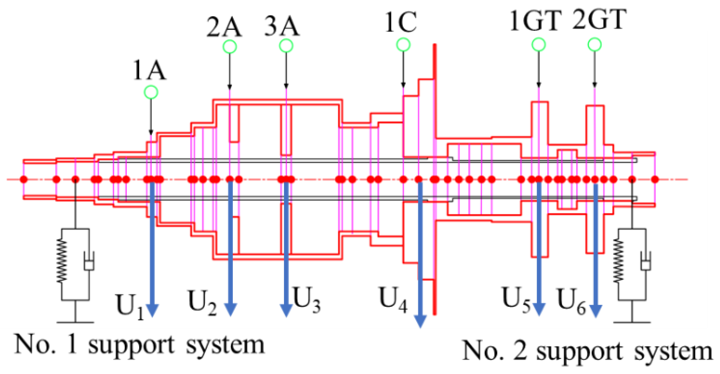
2. Dynamic Model of the Complex Variable Cross-Section Discontinuous Rotor Support System

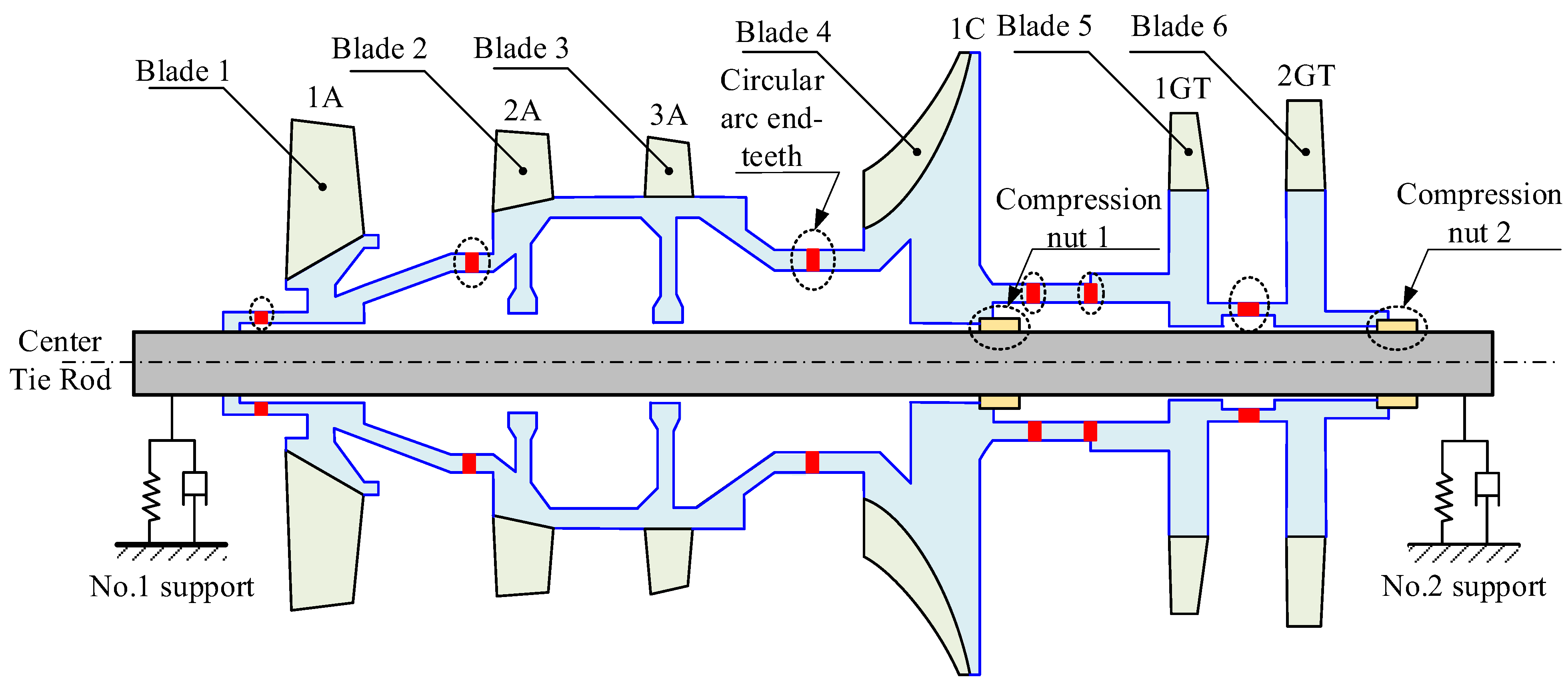
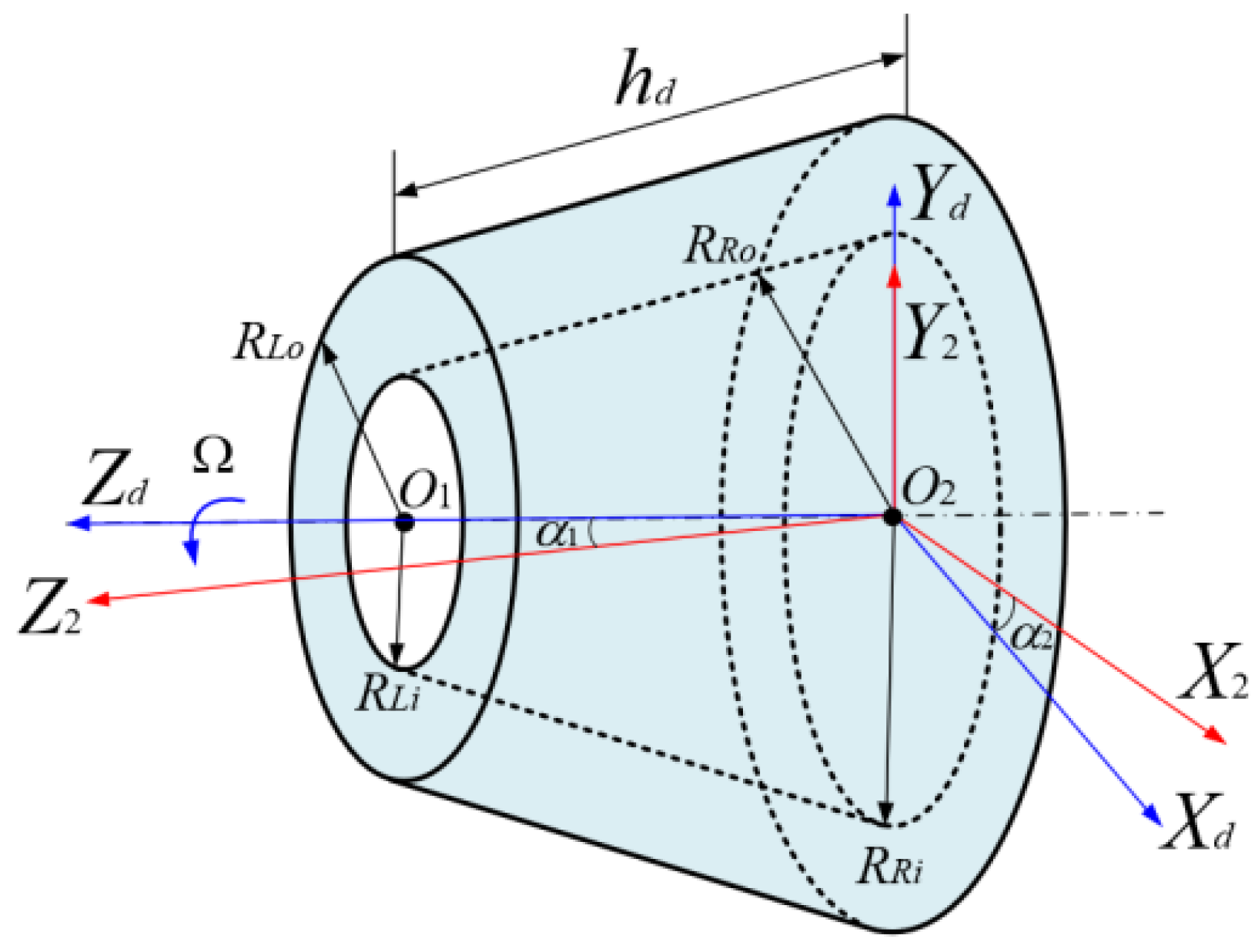
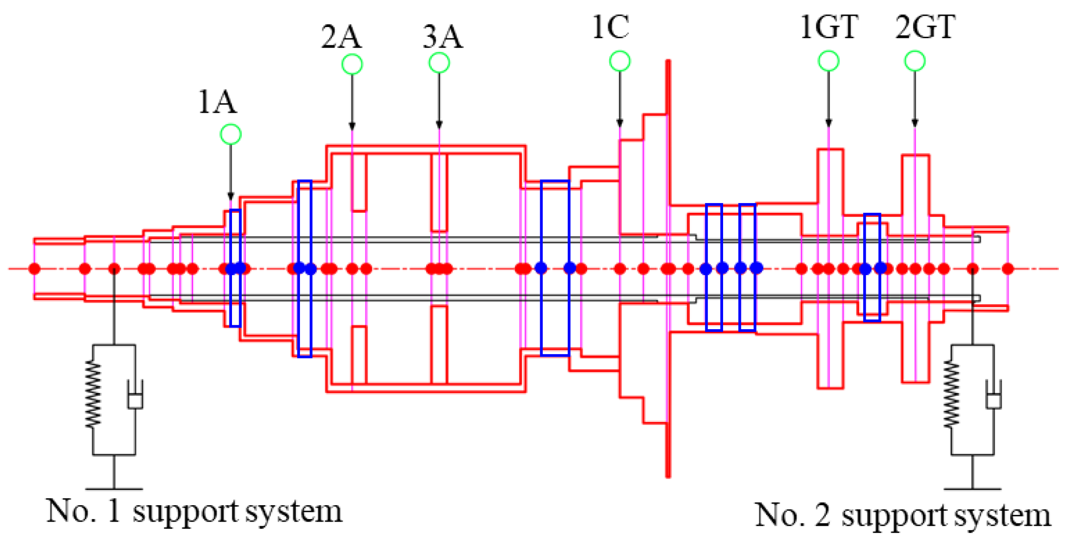
2.1. Description of the Model

As illustrated in Figure 1, a typical gas generator rotor system comprises critical components including the first-stage compressor blade disk (1A, TC4 titanium alloy), second/third-stage compressor blade disks (2A/3A, TC11 titanium alloy), centrifugal impeller rotor assembly (1C, TC11 alloy), first-stage gas turbine rotor assembly (1GT, GH4720Li superalloy), second-stage gas turbine rotor assembly (2GT, GH4720Li superalloy), central tie rod, preload nuts and bilateral support systems. To accurately capture the structural characteristics and dynamic properties of this complex system, the mathematical model must incorporate key elements: circular arc end-teeth connections, blade assemblies, compressor rotors, centrifugal impeller rotors, gas turbine rotors and support systems. Notably, operational factors such as residual rotor imbalance, misalignment and coaxial errors induce bending vibration effects in the circular arc end-teeth connections. These vibrations alter the mechanical behavior at the end-teeth contact interfaces, significantly impacting the overall dynamic performance of the turboshaft engine gas generator rotor system.
Through systematic equivalence processing of critical components (circular arc end-teeth, blades, compressor rotors and gas turbine rotors), this paper establishes a hierarchical modeling framework consisting of (1) an equivalent dynamic model for circular arc end-teeth connections, (2) a variable cross-section blade dynamics model and (3) a rotor disk dynamics model. This comprehensive model preserves the essential structural features of the gas generator rotor system (Figure 1) through the following component representations: the central tie rod is modeled using uniform cross-section beam elements, rotor disks and blades through variable cross-section beam elements, circular arc end-teeth structures via equivalent annular elements, preload effects at the centrifugal impeller and second-stage gas turbine assemblies through preload force simulations, and bilateral support systems through parallel spring-damper elements. Unlike many existing studies that simplify blade modeling to rigid-body assumptions for computational expediency, this paper critically incorporates a variable cross-section blade dynamics model, recognizing the significant influence of blade elastic deformation on overall system behavior. While often neglected, the first-order bending mode of the blades, although spatially distant from the rotor rigid-body mode, initiates elastic deformation that alters the distribution of rotational inertia of the disk, subsequently affecting the gyroscopic moment term—a factor that becomes paramount in high-speed rotation analysis. In the fundamental frequency vibration analysis, this deformation necessitates accounting for the aforementioned effect. Within this modeling framework, the rotor disks are treated as rigid bodies, while the remaining components are considered flexible bodies. This modeling strategy ensures faithful reproduction of the system’s mechanical characteristics while maintaining computational traceability.

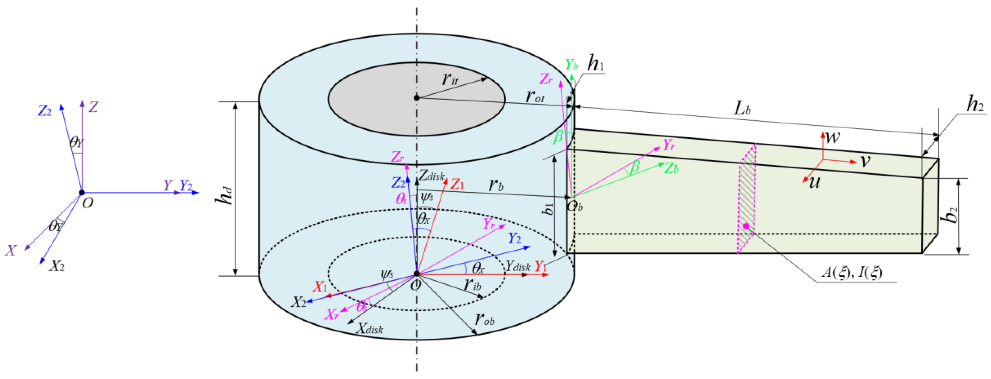
2.2. Model of Rotating Disk–Blade System

The rotor system of the gas generator comprises multiple rotor components arranged sequentially. To simplify the analysis, this section establishes a dynamic model of a disk–blade system using a hollow rigid disk and blades to represent various rotor components. The following assumptions are made to model the system:
(1)
The disk is treated as a rigid body, and its elastic deformation is disregarded;
(2)
The blade and disk are assumed to be rigidly connected, and nonlinear effects such as contact surface slip and clearance are ignored;
(3)
Load transfer occurs exclusively through the connection nodes, and local stress concentration or fatigue damage is not considered;
(4)
The influence of external excitations, such as aerodynamic loads and temperature gradients, is neglected.
The dynamic model of the disk was established using the centralized parameter method, as shown in Figure 2.
O2XdYdZd and O2X2Y2Z2 denote the position coordinate system and the swing coordinate system of the disk, respectively; α1 represents the angle between the coordinate axes Zd and Z2; α2 denotes the angle between the coordinate axes Xd and X2; RLi and RRi denote the inner diameters of the left and right ends of the disk, respectively; RLo and RRo separately denote the inner diameters of the left and right ends of the disk, respectively; and hd is the thickness of the disk. The expressions for the mass of the turntable Md, the diameter moment of inertia Jd and the pole moment of inertia Jp are shown below.
M d = M d i s k o d M d i s k i d ; M d i s k o d , i d = π ρ d h d R L o , i 2 + R L o , i R R o , i + R R o , i 2 3
J d = 1 2 J p o d J p i d + 1 12 M d i s k h d 2 ; J p = J p o d J p i d
J p o d , i d = 3 10 M d i s k o d , i d R 1 , 2 2 + M d i s k o d , i d d 1 , 2 2 + 3 sin 2 α 1 , 2 80 λ 1 , 2 h d 2 4 R 1 , 2 2 U ( x i y i )
where M d i s k i d and M d i s k o d denote the masses of the inner and outer disks, respectively. The detailed expression of R 1 2 , R 2 2 , λ1, λ2, α1, α2, d1 and d2 can be found in Ref. [26]. U(xiyi) is the step function.
Considering the transverse bending, axial deformation and torsional deformation of the rotor system, the kinetic energy expression of the disk is presented below.
T d i s k = 1 2 M d ( X . c 2 + Y . c 2 + Z . c 2 ) + 1 2 J d ( θ . X 2 + θ . Y 2 ) + 1 2 J p ( Ω + ψ . ) Ω + ψ . 2 θ . Y θ X
in which the symbols Xc, Yc and Zc represent the displacements of the disk center of mass along the Xd, Yd and Zd directions, respectively. θX and θY represent the transverse rotations along the Xd and Yd directions. Assuming that the disk has an eccentric mass in the thickness direction, the geometrical position relationship between the disk center of mass and the form center is shown below.
X c = X d i s k + e cos ( Ω t + ψ ) Y c = Y d i s k + e sin ( Ω t + ψ ) Z c = Z d i s k
wherein Xdisk, Ydisk and Zdisk denote displacements of the shape center of the disk along the Xd, Yd and Zd directions, respectively. e is the eccentric distance between the mass center and the shape center of the disk. Ω denotes the rotation speed, and ψ is the initial phase angle of the mass center of the disk.
The complex cross-sectional shape of blades in a gas generator rotor system is often simplified in existing studies to a concentrated mass point with centrifugal stiffening and gyroscopic effects, limiting the ability to characterize their form-face features. In this paper, the axial bending and tension–compression deformations of the blade cross-section are fully considered, and a variable cross-section beam unit is used to establish a variable cross-section blade dynamics model, effectively simulating geometrical changes in the width and thickness directions.
The model of the variable cross-section blade is shown in Figure 3. Lb denotes the length of the blade along the Xb direction. b1 and b2 separately represent the widths of the leaf root and tip positions along the Zb direction. h1 and h2 denote the thicknesses of the leaf root and tip positions along the Yb direction. u, v and w denote the deformation of the variable cross-section blade at any point Q on the tip of the blade in the Xb, Yb and Zb directions, respectively. ξ is the dimensionless position of any point of the variable-section blade along the Xb direction. The expressions for the blade width and thickness of any section of the variable-section blade along the Xb direction are as follows.
b ( ξ ) = b 1 1 + 1 η b ξ ; h ( ξ ) = h 1 1 + 1 η h ξ
in which ηb and ηh depict taper ratios of the variable cross-section blades along the Yb and Zb directions, respectively.
η b = 1 b 2 / b 1 ; η h = 1 h 2 / h 1
A(ξ) and I(ξ) denote the variable cross-section area and variable cross-section moment of inertia of the blade. When ξ = 0, A(ξ) and I(ξ) will degenerate to the variable cross-section area and variable cross-section moment of inertia at the leaf root of the variable cross-section blade, as expressed below.
A 1 = b 1 h 1 ; I 1 = b 1 h 1 3 / 12
Variable cross-section blades are typically mounted on the rotor disk assembly of an aerospace turboshaft engine. To facilitate the derivation of the energy expression for the rotating variable cross-section blades, the blades are modeled as cantilever beams and the disk as a centralized mass model, and a uniform distribution of nb variable cross-section blades is assumed. The i-th variable cross-section blade is selected for analysis, as shown in Figure 4.
In Figure 4, OXYZ, OXdiskYdiskZdisk, OXrYrZr and ObXbYbZb denote the overall coordinate system of the disk–blade coupling system, the disk coordinate system, the rotational coordinate system and the local coordinate system of the blade, respectively. Considering the elastic deformation of the i-th variable cross-section blade, the position vector of any point on the blade under the overall coordinate system of the disk–blade coupling system OXYZ is shown as follows.
r Q = X d i s k Y d i s k Z d i s k T + A 5 A 4 A 3 A 2 A 1 r b + x + u y φ v + y w T
where x, y and z denote the geometric coordinates of any point on the rotation variable-section blade along Xb, Yb and Zb under the local coordinate system ObXbYbZb, respectively. Xdisk, Ydisk and Zdisk denote the geometric coordinates of the disk along X, Y and Z under the overall coordinate system OXYZ, respectively. rb denotes the outer diameter of the disk at the blade connection position. Ai(i = 1,2,3,4,5) represent the transformation matrix between the coordinate systems OXYZ, OXdiskYdiskZdisk, OXrYrZr and ObXbYbZb, with the following expression.
A 5 = cos θ Y 0 sin θ Y 0 1 0 sin θ Y 0 cos θ Y ; A 4 = 1 0 0 0 cos θ X sin θ X 0 sin θ X cos θ X A 3 = 1 0 0 0 cos φ s sin φ s 0 sin φ s cos φ s ; A 2 = cos θ s sin θ s 0 sin θ s cos θ s 0 0 0 1 A 1 = 1 0 0 0 cos β sin β 0 sin β cos β
where β is the blade mounting angle; A1 denotes the rotational coordinate system OXrYrZr relative to the blade local coordinate system ObXbYbZb; A2 represents the disk coordinate system OXdiskYdiskZdisk relative to the rotational coordinate system OXrYrZr; A3 denotes the coordinate system OX1Y1Z1 relative to the disk coordinate system OXdiskYdiskZdisk; A4 denotes the coordinate system OX2Y2Z2 relative to the disk coordinate system OX1Y1Z1; and A5 denotes the coordinate system OXYZ relative to the disk coordinate system OX2Y2Z2.
The kinetic energy for the i-th rotating variable-section blade in a fixed coordinate system is given below.
T blade = 1 2 ρ b 0 L b A ( x ) r . Q 2 d x = 1 2 ( T 1 + T 2 + T 3 )
where ρb is the density of the blade. T1, T2 and T3 denote the kinetic energy without considering the torsional deformation of the rotating blade, considering the torsional deformation of the rotating blade or considering the rotation angle of the disk, which can be expressed as follows.
T 1 = ρ b 0 L b A ( x ) u . 2 + v . 2 2 u . θ . v cos β + 2 u v . θ . cos β + 2 ( x + r b ) v . θ . cos β + u 2 θ . 2 + v 2 θ . 2 cos 2 β + 2 u θ . 2 ( x + r b ) + θ . 2 ( r b + x ) 2 + x . d 2 + y . d 2 + 2 v . y . d s i n β d x + ρ b 0 L b I ( x ) ( 2 θ . φ . cos β + φ . 2 + θ . 2 cos 2 β + θ . 2 φ 2 ) d x
T 2 = ρ b 0 L b A ( x ) ψ [ 2 u . θ . ( R d + x ) + 2 ( x + R d ) v θ . 2 cos β ] + ψ 2 θ . 2 ( x + R d ) 2 + ψ . [ 2 u θ . ( x + R d ) + 2 θ . ( x + R d ) 2 + 2 v . ( x + R d ) cos β ] + ψ . 2 ( x + R d ) 2 d x + ρ b 0 L b I ( x ) ( 2 φ ψ θ . 2 + ψ 2 θ . 2 + 2 θ . ψ . cos 2 β + 2 φ . ψ . cos β + ψ . 2 cos 2 β ) d x
T 3 = ρ b 0 L b A ( x ) sin θ s ( 2 u . v . sin β 2 x ψ v . θ . sin β 2 v v . θ . cos β sin β 2 ψ v . θ . R d sin β 2 cos β v . x . d 2 u θ . x . d 2 x θ . x . d 2 x ψ . x . d 2 θ . R d x . d 2 ψ . R d x . d + 2 u . y . d 2 x ψ θ . y . d + 2 v θ . y . d cos β 2 ψ θ . R d y . d ) d x + ρ b 0 L b A ( x ) cos θ s 2 ( u + x ) v . θ . sin β + v . 2 sin 2 β + 2 v . θ . R d sin β + 2 v . ψ . ( x + R d ) sin β + 2 u . x . d 2 ( x + R d ) ψ θ . x . d 2 v θ . x . d cos β + 2 v . y . d cos β + 2 u θ . y . d + 2 ( x + R d ) θ . y . d + 2 ( x + R d ) ψ . y . d d x
Considering the effects of bending potential energy, axial compression, shear potential energy and centrifugal force, the potential energy expression for the i-th rotating variable cross-section blade is shown below.
U blade = 1 2 0 L b f c x v x 2 d x + 1 2 0 L b E b I ( x ) φ x 2 d x + 1 2 0 L b E b A ( x ) u x 2 d x + 1 2 0 L b κ b A ( x ) G b v x φ 2 d x
where Eb, Gb and κb denote the modulus of elasticity, shear modulus and shear factor of the variable cross-section blade, respectively. fc denotes the centrifugal force of the rotating variable cross-section blade, as shown in the following expression.
f c ( x ) = x L b d f c ( x ) = ρ b Ω 2 x L b A ( x ) ( r b + x ) d x
Based on the above derivation, the energy expression for the disk–blade system can be obtained as shown below.
T blade - disk = T disk + i = 1 n b T blade i U blade - disk = i = 1 n b U blade i
where nb is the number of blades in the disk.

2.3. The Model of the Circular Arc End-Teeth Connection Structures

In the gas generator rotor system of an aero-turboshaft engine, rotor components are interconnected through precisely machined circular arc end-teeth contact interfaces for power transmission and structural connection. Insufficient machining precision results in surface roughness at contact surfaces, leading to a reduced effective contact area, stress concentrations, geometric and mass discontinuities and subsequent stiffness degradation. Under bending loads, the diminished adhesive contact area further compromises load-bearing capacity and structural stiffness. Consequently, dynamic modeling of the rotor system must account for stiffness degradation caused by variations in contact area, alterations in contact characteristics and bending deformation of preloaded multi-rotor assemblies.
Based on the theory of solid mechanics and interface contact mechanics, stiffness loss caused by the circular end-tooth structure is primarily attributed to the following three reasons:
(1)
Variation in contact area at the contact interface of the circular end-teeth
The contact interface of circular arc end-teeth exhibits surface roughness. When surface roughness is non-zero, the actual contact area is smaller than the nominal contact area. Under the same load, this reduction in effective contact area leads to increased structural deformation and reduced overall stiffness. Furthermore, rotor-bending vibrations can induce separation at the tooth interface, further decreasing the effective contact area. Consequently, the loss coefficient of actual contact area relative to the theoretical value can be expressed as
η 1 = ( A C A a c t ) / A C
where AC denotes the nominal contact area of any contacting tooth face of the circular end-teeth, and Aact is the actual contact area of any contacting tooth face of the circular end-teeth.
(2)
Variation in contact properties at the contact interface of the circular end-teeth
The roughness of the circular arc end-tooth interface can be characterized by asperities with varying heights. Assuming material homogeneity, micro-asperities on the contact surface exhibit only geometric differences in morphology, with all other properties remaining consistent. The varying local deformation states of asperities under external loads lead to distinct contact characteristics, which can be categorized as elastic, elastoplastic and plastic contact. These differences in contact characteristics result in variations in contact stiffness under identical contact area conditions. To quantitatively characterize the impact of changing interface contact characteristics, the interface contact effect corrective coefficient η2 is typically employed:
η 2 = K 2 / K 2
where K2 is the interfacial stiffness without contact effects, and K 2 is the interface stiffness considering contact effects.
(3)
Bending deformation of preloaded combined rotors
The gas generator rotor employs axial preload to enhance structural stiffness; however, this process introduces additional torque, which degrades the connection structure’s stiffness. Consequently, when analyzing the bending deformation of the preloaded built-up rotor structure, a bending deformation correction factor η3 must be incorporated to accurately characterize the stiffness:
η 3 L = 1 1 3 u 1 3 tan u 1 u 1 ; η 3 R = 1 1 3 u 2 3 tan u 2 u 2
in which u1 and u2 denote the bending deformation produced by the preload force on the end-teeth structure at both ends, respectively.
To summarize, considering the stiffness loss caused by changes in contact area, contact characteristics and bending deformation of preloaded gas generator rotors, the overall stiffness loss correction factor for the circular arc end-tooth structure under bending vibrations is expressed as follows:
η = η 1 η 2 η 3
Therefore, the contact stiffness of the circular arc end-teeth structure can be derived by the stiffness degradation model [4].
K c o n t a c t = η K c o n t a c t p
in which Kcontact denotes the contact stiffness, and K c o n t a c t p represents the contact stiffness of smooth interfaces of the circular arc end-teeth structure under the initial preload axial load.
Based on the principle of an equivalent ring and Equation (22), this paper establishes an equivalent model of the circular arc end-teeth connection structure under the consideration of bending deformation-influencing factors, as shown in Figure 5.
The strain energy of the circular arc end-teeth connection structure under the normal preload force Fc is as follows.
W c = b L F c 2 2 E L A c + b R F c 2 2 E R A c + F c 2 2 K c o n t a c t
where EL and ER are the moduli of elasticity of the left and right end teeth; Ac denotes the contact area of the end-teeth structure; bL and bR denote the thicknesses of the left and right end teeth; and bc is the thickness of the connecting region of the end-teeth. The strain energy of the equivalent ring for the circular arc end-teeth is as follows.
W d = F c 2 2 E e q u A c b L + b R
in which Eequ denotes the elastic modulus of the equivalent ring. According to the principle that the strain energy remains unchanged before and after the equivalence of the circular end-tooth connection structure, Wc = Wd, the expression of Eequ is specified as follows.
E e q u = K c o n t a c t E L E R b L + b R K c o n t a c t b L E R + K c o n t a c t b R E L + A c E L E R
To maintain constant mass before and after the equivalent structure of the circular arc end-teeth connection, the expression for the density of the equivalent ring is specified as follows.
ρ e q u = ρ L V L + ρ R V R V L + V R
The equivalent Poisson’s ratio can be obtained from the relationship between the normal and transverse strains in the contact process of the circular arc end-teeth.
ε c = μ · ε h = μ L F c b L E L A c + μ R F c b R E R A c + F c μ L + μ R 2 K c o n t a c t b L + b R
where the symbols μL and μR indicate Poisson’s ratio of the left and right end-teeth. εc and εh denote the normal strain and transverse strain of the circular arc end-teeth connection structure, respectively, and the relationship between the normal strain and transverse strain of the equivalent ring is as follows:
ε e q u c = μ e q u ε e q u h = μ e q u F c E e q u A c
According to the principle that the normal strain remains unchanged before and after the equivalence of the circular arc end-teeth connection structure, the expression of Poisson’s ratio for the equivalent ring is specified as follows.
μ e q u = μ L F c b L E L A c + μ R F c b R E R A c + F c μ L + μ R 2 K c o n t a c t E e q u A c F c b L + b R
There are six circular arc end-teeth connection structures in the aeroengine rotor system studied in this paper, as shown in Figure 6. The equivalent ring modeling method based on the virtual material layer method is used for the equivalent substitution of the six circular arc end-teeth connection structures, and the resulting equivalent model parameters are shown in Table 1.

2.4. The Model of Support Systems with Squeezed Film Dampers

Squeezed film dampers (SFDs) offer several advantages, including a simple structure, effective vibration damping and high reliability, meaning they are widely used in aviation gas generator rotor support systems. In this paper, an elastic support model composed of parallel springs and damping units is used to simulate the SFD support system, and a dynamic model of the SFD support system is established. This is shown in Figure 7, where Figure 7a represents the elastic support model and Figure 7b represents the mechanical model of the squeeze film.
To develop an analytically tractable squeeze film dynamic model, this study adopts classical hydrodynamic lubrication theory based on the following four fundamental assumptions:
(1)
Negligible film inertia effects, excluding fluid acceleration terms from the momentum equations;
(2)
Incompressible Newtonian lubricant satisfying mass conservation;
(3)
Constant dynamic viscosity coefficient μ within operational temperature ranges;
(4)
Dominant circumferential pressure gradient over radial direction, establishing quasi-steady pressure distribution.
Based on the above assumptions, the simplified control equations for the extruded oil film force are as follows.
1 R S F D 2 θ h 3 p θ + z h 3 p z = 12 μ S F D ϕ . h θ + 12 μ S F D h t
where μSFD and RSFD denote the viscosity and radius of the oil film. ϕ . denotes the rotational angular velocity of the rotary axis; and p and h denote the pressure and thickness of the film, with the specific expressions as follows.
p θ , z = 6 μ S F D ϕ . C S F D ε S F D sin θ h 3
h = C S F D 1 ε S F D cos θ
where CSFD represents the radial clearance of the film; and eSFD and εSFD represent the eccentric distance and eccentricity ratio of the shaft neck, which exist the following relationship.
ε S F D = e S F D / C S F D
By solving Equation (30), the squeezing film force can be obtained, which can be decomposed to the radial and transversal squeezing film forces.
F r = μ S F D R S F D L S F D 3 C S F D 2 ϕ . e S F D 2 ε S F D 1 ε S F D 2 2 + e . S F D π 2 ε S F D 2 + 1 2 1 ε S F D 2 2.5 F t = μ S F D R S F D L S F D 3 C S F D 2 ϕ . e S F D π 2 1 ε S F D 2 1.5 + e . S F D 2 ε S F D 1 ε S F D 2 2
where LSFD denote the length of the oil film; and Fr and Ft denote the radial and tangential forces of the squeezing oil film. As shown in Figure 7a, through force decomposition and synthesis, the radial and tangential forces in the circumferential direction are transformed into forces in the x and y directions of coordinate system O-x-y:
F S F D x = F r cos ϕ F t sin ϕ = K x x C x x . F S F D y = F r sin ϕ + F t cos ϕ = K y y C y y .
in which FSFDx and FSFDy are the squeezing film force component in the coordinate system O-x-y; and Kx, Ky, Cx and Cy represent the oil film support stiffness and support damping in the x and y directions, which can be seen from Figure 7a. In the modeling of this article, it is assumed that the squeeze film damper satisfies the following conditions: 1. The structure is radially symmetrical and the oil film gap is uniform. 2. The external load is mainly radial unidirectional load, and circumferential disturbance can be ignored. 3. The neck movement speed is stable and does not cause significant oil film cross-coupling vibration. Based on the above conditions, the cross-coupling stiffness (Kxy, Kyx) and damping (Cxy, Cyx) components of the oil film reaction are much smaller than the radial principal components (Kx, Ky, Cx, Cy). Therefore, this part of the coupling effect is ignored in the model, and only the independent stiffness and damping parameters in the x/y direction are retained. Through coordinate transformation, the squeeze oil film force of Equation (35) in the rotating coordinate system can be expressed as
F S F D x F S F D y = K S F D ω C S F D ω C S F D K S F D x y
where x′ and y′ are the displacement component in the rotating coordinate system; and KSFD and CSFD indicate the oil film support stiffness and support damping provided by the SFD, respectively.
K S F D = 2 μ S F D R S F D L S F D 3 ε S F D ϕ . C S F D 3 1 ε S F D 2 2 ; C S F D = π μ S F D R S F D L S F D 3 2 C S F D 3 1 ε S F D 2 1.5

2.5. Solution Procedure

In summary, this paper has constructed the dynamic model of a disk-variable cross-section blade, the dynamic model of a circular arc end-teeth connection structure and the dynamic model of a support system containing SFD. In this section, the gas generator rotor system dynamics model will be solved by the differential quadrature finite element method (DQFEM) [27,28], as shown in Figure 8. As an efficient numerical method that combines the high-precision discretization characteristics of the differential quadrature method (DQM) with the structural adaptability of the finite element method (FEM), DQFEM constructs differential quadrature operators by introducing Lagrange interpolation polynomials within the elements, transforming complex differential equations into algebraic equations and proving particularly suitable for dynamic analysis of variable cross-section and discontinuous structures.
The DQFEM model of the actual rotor consists of 47 hollow beam elements; 6 elements, marked in blue, represent the six circular arc end-teeth coupling connection structures C1, C2, C3, C4, C5 and C6. After discretizing the actual rotor into beam elements, the mass matrix, gyroscopic matrix and stiffness matrix for each beam element are calculated based on their geometric and material parameters. Finally, these matrices are assembled to form the overall matrix. Consequently, the dynamic equation of the complex variable cross-section discontinuous rotor support system is as follows:
M T + M r q ¨ r + C t + C r + Ω G q . r + K t + K r q r = F u + F S F D
where MT, Mr, Ct, G and K are the system mass, rotational inertia, damping, gyroscopic and stiffness matrices, respectively; Ω represents the rotational angular velocity; Fe is the unbalance excitation force; FSFD represents the squeeze film force generated by the squeeze film damper on the shaft; and the displacement vector and damping matrix can be expressed as
q = [ x L , y L , θ x L , θ y L , x R , y R , θ x R , θ y R ] ;   C r = α M r + β K r
where α and β can be calculated by the following formula:
α = 2 ( ε 2 / ω 2 ε 1 / ω 1 ) / ( 1 / ω 1 1 / ω 2 ) β = 2 ( ε 2 ω 2 ε 1 ω 1 ) / ( ω 2 2 ω 1 2 )
where ε1 and ε2 are the damping coefficients of the rotor system, which are determined by the material loss factor and frequency response function; and ω1 and ω2 are the first two critical speeds of the rotors.
In the usual case, the unbalance of the rotor is distributed along the axial direction, with different eccentricities e and phase angles ϕu for each unit. Therefore, the unbalance at any axial position can be represented in the rotating coordinate system as follows:
U z = m z e z = u x z + i u y z = U z × e i ϕ u z
where m(z) represents the magnitude of the unbalance, and ϕu(z) represents the initial phase angle of the unbalance, both of which determine the unbalance vector U(z).
According to D’Alembert’s principle, when the rotor system is under steady-state conditions, the unbalance force at any position on the rotor can be expressed as
  F u = F ux F uy = m e Ω 2 cos ( Ω t + ϕ u ) m e Ω 2 sin ( Ω t + ϕ u ) e = e x + i e y = e × e i ϕ u

3. Numerical Example and Discussion

Following the establishment of the gas generator rotor system dynamics model, this section details the calculation and analysis of the rotor system’s unbalance response. Initially, the effects of axial and circumferential unbalance positions are quantified. Subsequently, a detailed analysis of the rotor system’s unbalance measure limit value is performed, and the model’s accuracy is verified through experimental study.

3.1. Analysis of Unbalance Response Characteristics of the Aeroengine Rotor Support System

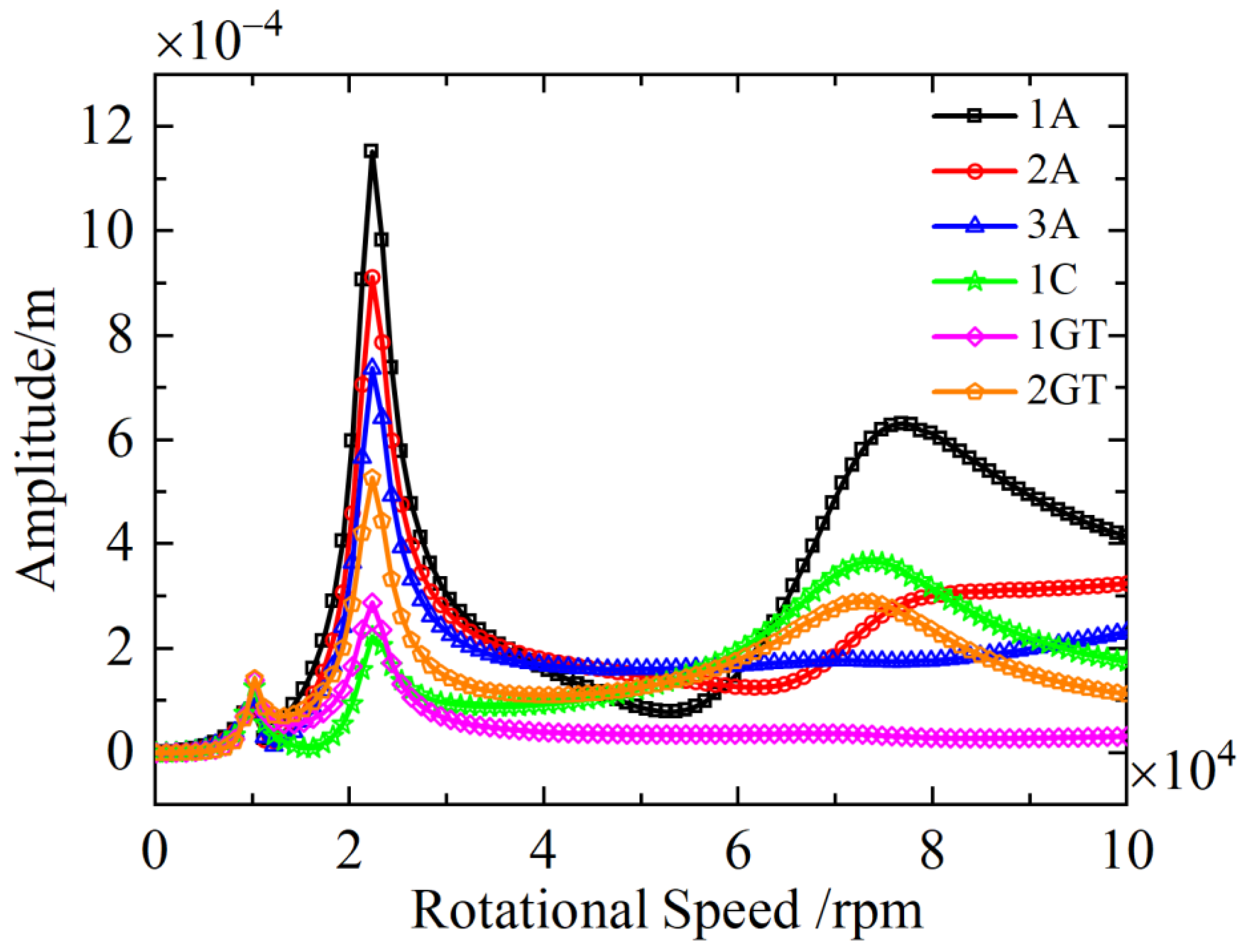
3.1.1. The Influence of Unbalance Mass at Different Axial Distributions on the Unbalance Response

Figure 9 shows a schematic diagram of the axial position distribution of unbalance mass in the aeroengine rotor shown in Figure 1. U1 represents the unbalance mass at 1A (first-stage axial flow compressor); U2 is the unbalance mass at 2A (second-stage axial flow compressor); U3 is the unbalance mass at 3A (third-stage axial flow compressor is considered); U4 is the unbalance mass at 1C (centrifugal compressor); U5 is the unbalance mass at 1GT (first-stage gas turbine); and U6 is the unbalance mass at 2GT (second-stage gas turbine).
Based on the presented dynamic model of the aeroengine rotor support system, the unbalanced response characteristics of the rotor with unbalance mass 12 g, which are provided by the balance accuracy grade G2.5, at six axial positions are studied, and the analysis results are shown in Figure 10 and Table 2.
Analysis of the data in Figure 10 and Table 2 reveals that the sensitivity of the unbalanced response to the axial position of the unbalance mass varies with different critical speeds. At the first critical speed, the unbalanced response exhibits high sensitivity to the unbalance mass across all axial positions; the amplitude of the response increases as the unbalance mass approaches the rotor support system’s center of mass (1C). At the second critical speed, the sensitivity decreases in the order of 1A, 2A, 2GT, 3A, 1GT and 1C, demonstrating that the rotor support system operating at this critical speed is more sensitive to excitations farther from the center of mass (1C). Finally, at the third critical speed, the unbalanced response is notably sensitive to the unbalance mass at positions 1A, 1C and 2GT, while the influence of the unbalance mass at positions 2A, 3A and 1GT is minimal.
Figure 11 presents the first three modal shapes of the aeroengine rotor system. As observed from the diagram, the first mode exhibits synchronous vertical vibrations across all disks with an identical phase and direction. The second mode demonstrates a two-segment vibration pattern with opposing directional characteristics, where the disks near the bearing supports exhibit pronounced amplitude responses. Notably, the amplitude distribution of the third mode is closely associated with the critical speed characteristics: as indicated in Figure 10, the critical speeds of components 2A, 3A and 1GT are significantly higher than those of 1A, 1C and 2GT, which results in relatively reduced peak responses in the third modal shape.
In summary, this analysis demonstrates that the axial positions of the unbalance masses at 1A, 1C and 2GT exhibit the highest sensitivity to vibrational responses. By implementing strategic adjustments to these axial positions, the unbalance-induced vibrations under the second- and third-order critical speeds can be substantially reduced. This underscores the critical importance of precise control over unbalance mass distribution at key components, including the first-stage axial-flow compressor, second-stage gas turbine and first-stage centrifugal compressor, to ensure structural vibration safety and operational stability. Furthermore, as revealed by the rotor modal shape diagram, the first three displacement modes of rotor vibration correspond to translational motion, pitching motion and first bending mode, respectively. By redistributing the unbalance mass, the localized vibration amplitudes (i.e., the vibrational responses at individual-stage disks) can be effectively regulated. This provides a targeted approach for mitigating high-amplitude oscillations at specific rotor sections while maintaining overall system stability.

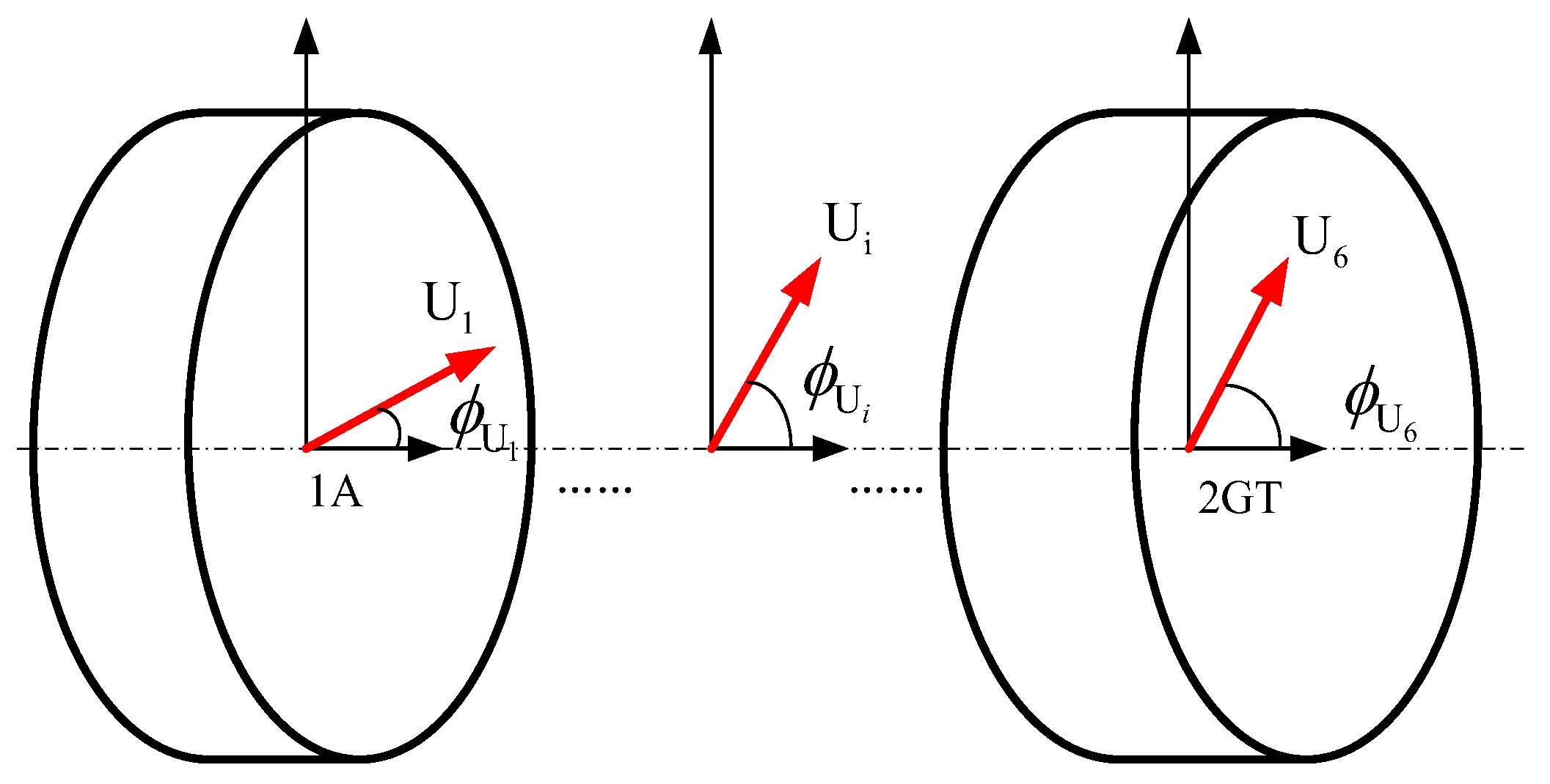
3.1.2. The Influence of Unbalance Mass at Different Circumferential Positions on the Unbalance Response

As depicted in Figure 12, the circumferential positions of the rotor’s unbalance mass can be represented by the phase angles of the unbalance mass. In this analysis, all phase angles are measured relative to the 1A sensor position (defined as 0° reference) according to rotor dynamics conventions. Given the centro symmetry of the rotor support system, the influences of phase angle differences of 30° and 330° relative to 1A are identical. Consequently, phase angle differences ranging from 0° to 180° relative to the 1A reference are representative, defining seven distinct circumferential unbalance distribution scenarios. This relative phase framework leverages the principle of phase invariance: since the rotor is centrosymmetric, any absolute angular reference (e.g., geometric datums) is unnecessary. Instead, we quantify unbalance distribution through the controlled relative phase difference between the 2GT and 1A measurement points. This approach sufficiently captures how an unbalance orientation affects the vibration response while circumventing complexities of absolute reference definitions—a well-established methodology in rotating machinery vibration analysis.
The simulation results of unbalance responses caused by the unbalance mass of seven circumferential positions at the most sensitive axial positions (1A and 2GT) are as shown in Figure 12 and Table 3.
Analysis of the data in Figure 13 and Table 3 reveals several key relationships between phase angle differences and unbalanced responses at various critical speeds. At the first and third critical speeds, unbalanced responses increase as the phase angle difference approaches 0°, whereas the response at the second critical speed diminishes. This suggests that near-alignment of unbalance masses (phase angle near 0°) amplifies specific vibration modes, the effect of which is dependent on the rotor’s operational speed. Conversely, as the phase angle difference approaches 180°, the unbalanced response at the second critical speed increases, while responses at the first and third critical speeds decrease. This indicates that positioning the unbalance masses approximately 180° apart tends to enhance vibrations at intermediate speeds while mitigating them at lower and higher speeds. Notably, when the phase angle difference surpasses 150°, the amplitude of the unbalanced response at the third critical speed may diminish so drastically as to almost disappear, with no discernible peak in the response curve. This phenomenon highlights the sensitive nature of high-speed rotor dynamics to the precise angular distribution of unbalance masses.
These observations indicate an inverse relationship between the impact of the circumferential unbalance mass position on responses at the first and third critical speeds and its effect at the second critical speed. Consequently, optimizing a rotor for one speed range may inadvertently exacerbate issues at others, emphasizing the need for a balanced design and operational approach. To effectively minimize the rotor vibration amplitude, adjustment of the circumferential phase angle difference in residual unbalance mass is crucial, tailored to the specific operating speed range. By carefully managing the relative positioning of unbalance masses, engineers can tailor the rotor’s dynamic behavior to achieve the optimal performance and stability across all operational scenarios.

3.2. Analysis of Vibration Reduction of the Aeroengine Rotor Support System

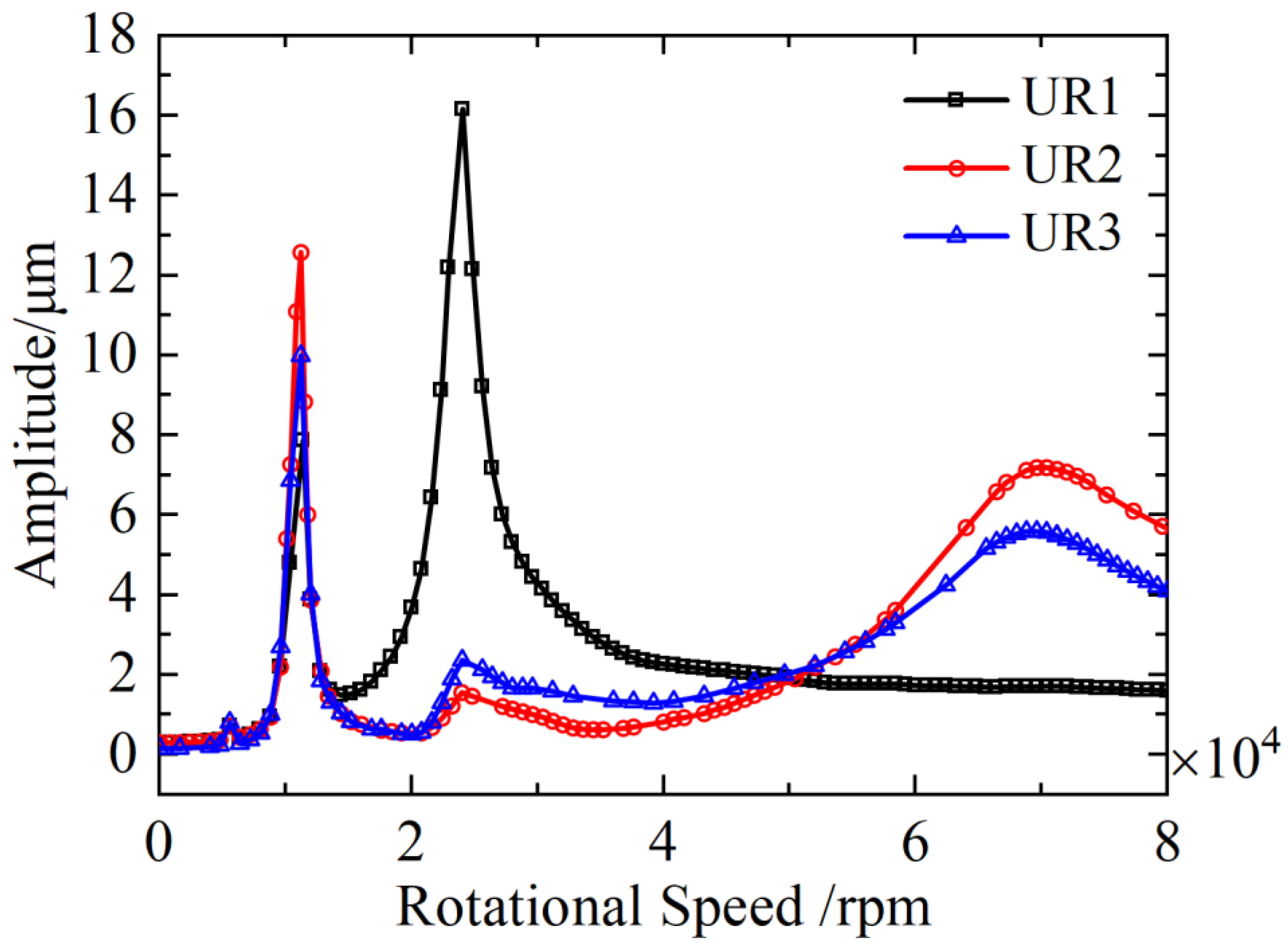
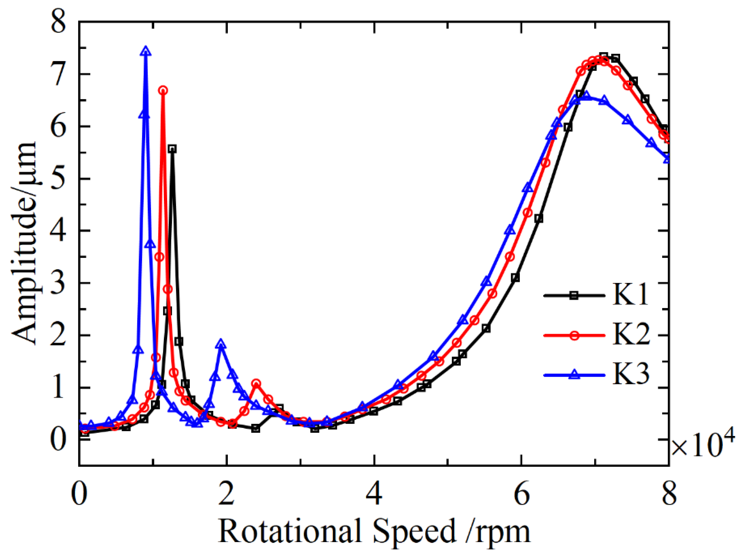
3.2.1. Vibration Reduction of Rotor Support Systems Based on the Unbalance Response Characteristics

Drawing on the unbalance response characteristics, which are affected by the position of the unbalance mass, three vibration reduction methods for the unbalance response of rotor support systems are proposed, as detailed in Table 4. With the unbalance mass set at 12 g, the vibration responses of the rotor support system corresponding to the three different unbalance distribution methods have been simulated, and the results are presented in Figure 9.
The analysis of Figure 14 reveals significant variations in rotor unbalance responses under different mass configurations. When maintaining a constant unbalance mass magnitude while altering its circumferential position, distinct patterns emerge across the first three critical speeds. Specifically, positioning the mass at UR 1 amplifies the first critical speed response while attenuating the second. Conversely, UR 2 placement maximizes third critical speed vibration while reducing second critical speed effects. The UR 3 configuration exhibits an inverse relationship, peaking at the second critical speed and diminishing responses at the first and third. This positional sensitivity demonstrates that strategic mass redistribution can effectively modulate vibrational energy distribution across critical speed regimes.
The vibration mitigation strategy leverages these operational characteristics through speed-dependent position optimization. For rotational speeds below 15,000 rpm, UR 1 positioning proves most effective in suppressing system vibration. As rotational speed increases between 15,000 and 50,000 rpm, optimal suppression shifts to the UR 2 configuration. At ultrahigh speeds exceeding 50,000 rpm, up to 80,000 rpm, the UR 3 positioning becomes the preferred countermeasure. This tiered approach aligns mass redistribution with dynamic system behavior across operational ranges, enabling targeted vibration control through coordinated phase manipulation within the combined support architecture.

3.2.2. Vibration Reduction of Rotor Support Systems Based on the Characteristics of Combined Support Systems

Simulation results of the unbalance responses with different parameters of the combined support system are shown in Figure 15 and Figure 16. The support stiffnesses are K1 (15,000 N/mm), K2 (25,000 N/mm) and K3 (35,000 N/mm), and the damping C1 and C2 are 1 N·s/m and 200 N·s/m.
Upon examining Figure 15 and Figure 16, several key insights emerge regarding the influence of support stiffness and damping on the critical speeds and vibration response amplitudes of a rotor support system. The support stiffness primarily affects both the critical speeds and the vibration response amplitudes of the rotor support system, playing a key role in determining the system’s natural frequencies. In contrast, damping primarily influences the vibration response amplitude and does not significantly alter the critical speeds, indicating that while damping is effective in controlling vibrations, it does not have a substantial impact in changing the system’s inherent dynamic characteristics. The first three critical speeds and their corresponding vibration response amplitudes exhibit a high sensitivity to variations in support stiffness. As the support stiffness decreases, there is a noticeable reduction in these critical speeds, and concurrently, the vibration response amplitudes at these critical speeds increase, highlighting the importance of maintaining adequate stiffness for stable operation.
Therefore, increasing damping can effectively mitigate the vibration response of the rotor system across its operating speeds. Based on these findings, a vibration reduction strategy utilizing combined support characteristics can be outlined. For rotor systems operating at speeds exceeding 30,000 rpm, it is advisable to maximize the support stiffness to ensure that the critical speeds are well above the operational range, thereby minimizing the risk of resonance and associated excessive vibrations. When the rotor operates at speeds below 30,000 rpm, the selection of support stiffness should be tailored to the specific rotational speed, allowing for optimal tuning of the system to achieve a balance between stability and vibration control, ensuring efficient and smooth operation while avoiding unnecessary stiffness increases that could lead to other mechanical issues.

3.3. Experimental Validation

To validate the unbalanced response law and vibration reduction method for the complex variable cross-section discontinuous rotor support system, a test bench was designed and constructed, as shown in Figure 17, following the methodology of simulated-rotor test benches commonly used for complex rotors. The test bench incorporates a discontinuous rotor connected by end-teeth couplings, a preloading device, couplings, the support system, an oil supply system, a base, a safety protection cover, a drive motor, a frequency converter controller and a vibration testing system. The test rotor was designed to exhibit dynamic characteristics similar to the actual rotor studied in this paper. To achieve this, the critical speeds of the test rotor were scaled to 1/16th those of the actual rotor. While the actual rotor’s first three critical speeds are 11,200 rpm, 24,000 rpm and 70,000 rpm, the corresponding scaled critical speeds for the test rotor are 700 rpm, 1500 rpm and 4250 rpm. Due to manufacturing tolerances and design constraints, the test primarily ensured dynamic similarity of the first two critical speeds. Considering the typical operating speeds of aeroengine rotors (15,000–50,000 rpm), the corresponding test rotor speeds ranged from 940 rpm to 3200 rpm. For safety reasons, the testing speed in this study was limited to 1500 rpm.

3.3.1. Experimental 1: Validation of the Vibration Reduction Method Based on the Unbalance Response Characteristics

The primary goal of this study is not to achieve engineering-level rotor balancing but to systematically quantify the impact of different unbalance distribution patterns on vibrational responses. Unlike traditional methods such as the Influence Coefficients Method (ICM) or Modal Balancing Method (MBM), which aim to eliminate unbalance, our approach enables precise control and manipulation of axial and circumferential unbalance distributions to investigate their causal relationship with vibrational behavior. To achieve that core objective, this section will present a vibration reduction method validation experiment based on unbalance response characteristics, with the specific experimental steps outlined below:
(1)
Install the test rotor on the test bench and deploy sensors: Acceleration sensors are installed at the positions of the left and right supports, an eddy current displacement sensor is installed at the centroid of the rotor and a photoelectric sensor is installed on the right side of the shaft. Then, open the testing software, configure the sensor information and set the test conditions;
(2)
Inspect and debug the equipment. The drive motor is connected to the right end of the rotor through a coupling to drive the rotor to rotate. The rotational speed of the rotor system is controlled by changing the voltage through the motor speed controller. The magnetic hydraulic control switch is used to fill the inside of the support structure with hydraulic oil. After low-speed trial operation is safe and error-free, turn off the relevant equipment;
(3)
Turn on the oil pump and start the motor to collect the vibration signals of the rotor support system at different rotational speeds;
(4)
Complete data collection work, disassemble and tidy up the test bench.
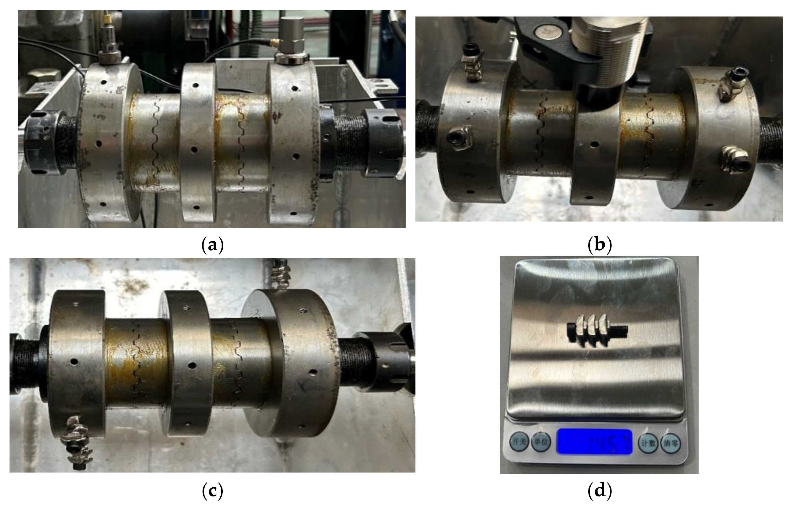
Three unbalance setting schemes are adopted in this test. Unbalance is added at different positions of the rotor disk through the combination of standard screws and counterweights, as follows:
(1)
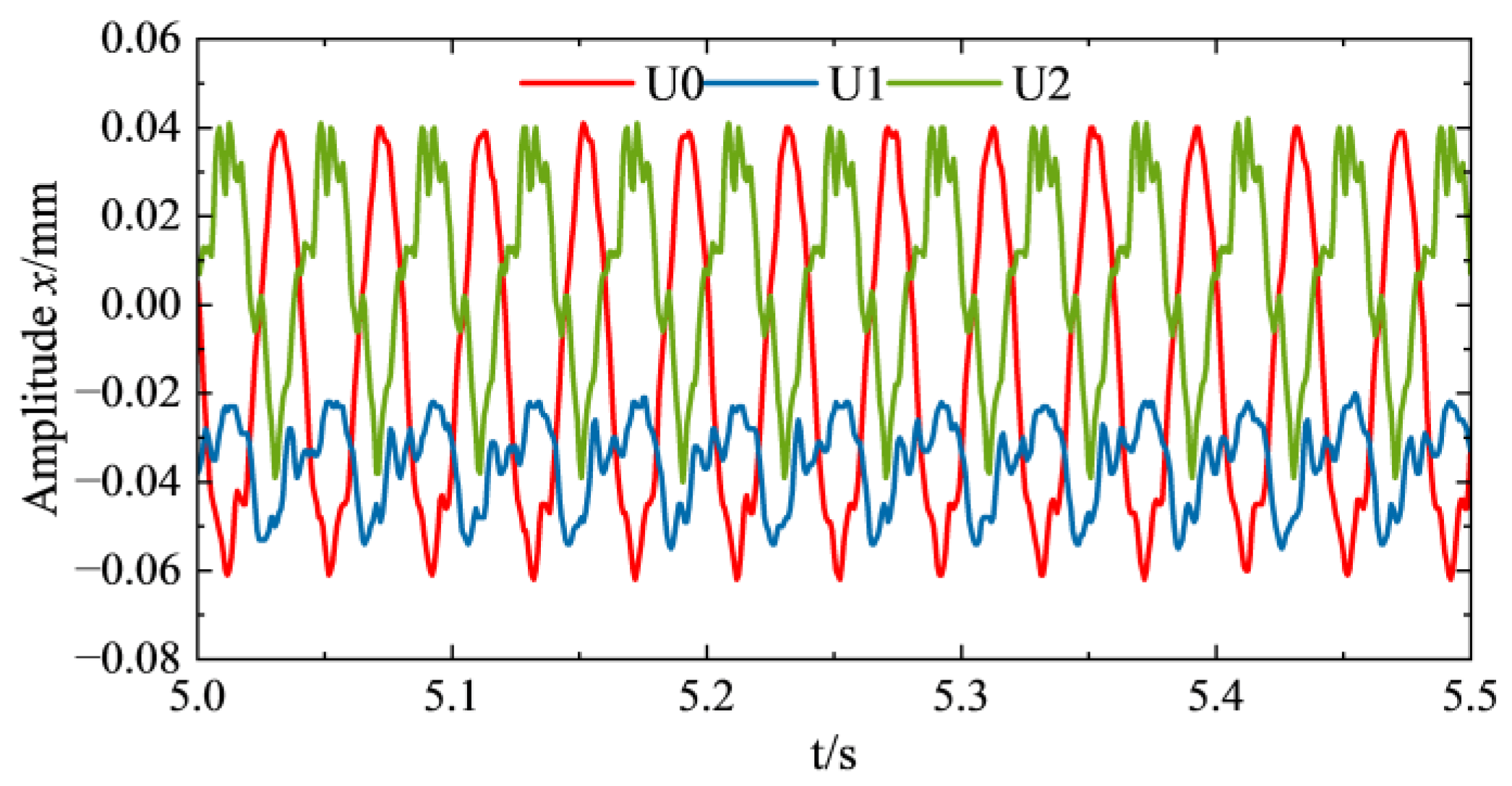
The three-point dynamic balancing method was used to calibrate the initial unbalance of the test rotor, and the initial unbalance mass of the left calibration disk was measured to be 81.92 g with a phase of 0° (as shown in Figure 18a), which was recorded as the initial unbalance state U0. The motor is started under this condition and the vibration response signal of the rotor system in the initial unbalance state is collected.
(2)
A weight block of 14.57 g (single mass block, as shown in Figure 18d) is attached via standard screws, and an unbalanced mass is attached at a specific circumferential position of the left and right calibration disks to adjust the initial unbalanced state U₀ to the U₁ state: 55 g unbalanced mass in the left disk at 0° phase, and 26.92 g unbalanced mass in the right disk at 0° phase (as shown in Figure 18b). After completing the counterweight installation, the test system is restarted to collect the rotor vibration response signals for this unbalance distribution state.
(3)
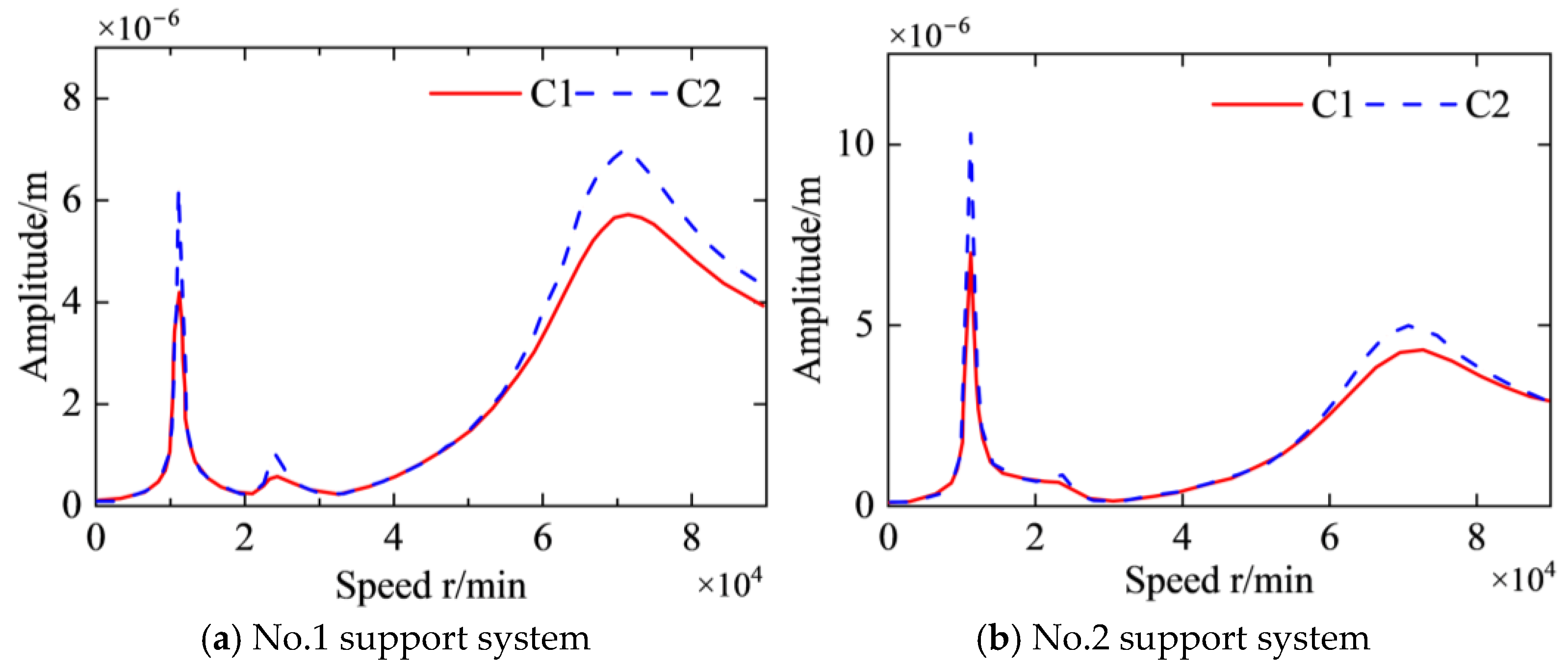
Keeping the unbalanced state of the left disk unchanged, a 14.57 g counterweight block is attached to the circumferential position of the right calibration disk by the same counterweight method, and the unbalanced phase of the right disk is adjusted to 180°, forming a U₂ state: 55 g/0° for the left disk and 26.92 g/180° for the right disk (as shown in Figure 18c). The test stand is started again to collect the rotor vibration response data under this axial asymmetric unbalance distribution.
Based on the experimental results presented in Figure 19 and Figure 20, several conclusions can be drawn. Adjusting the unbalance distribution pattern effectively reduces vibration responses in discontinuous rotor support systems while maintaining equivalent unbalance masses. Specifically, the U1 unbalance distribution predominantly excites first- and second-order vibration responses that dominate at lower rotational speeds, whereas the U2 distribution primarily induces third-order responses affecting higher-speed regions. Notably, the U1 configuration demonstrates optimal vibration suppression at 1500 rpm, a rotational speed situated between the first and second critical speeds. This finding underscores the necessity of tailoring unbalance distribution patterns according to operational speed ranges to achieve effective vibration mitigation in practical applications.
The experimental configurations employed three distinct unbalance distributions: U0 (single unbalance mass at position 1A), U1 (UR2 distribution pattern) and U2 (UR3 distribution pattern), with UR1 representing an alternative configuration at position 1C. Analysis of vibration response characteristics and damping effectiveness reveals a consistent hierarchy at 1500 rpm: U0 > UR1 > U2 > U1 in descending order of vibration magnitude. Figure 19 confirms remarkable consistency between experimental measurements and numerical simulations, thereby validating both the identified unbalance response mechanisms and the proposed vibration reduction methodology. This experimental–theoretical correlation provides robust verification for the vibration control strategies developed in this study.

3.3.2. Experimental 2: Validation of the Vibration Reduction Based on the Characteristics of Combined Support Systems

The experimental procedure for reducing the unbalance response in the rotor-bearing system, considering the influence of an unbalance distribution, is as follows:
(1)
The test rotor is mounted on the SFD-elastic support system and connected to the motor via diaphragm coupling, and sensors are then positioned;
(2)
The oil supply system is activated, the motor is started and vibration signals from the rotor support system are collected at various speeds;
(3)
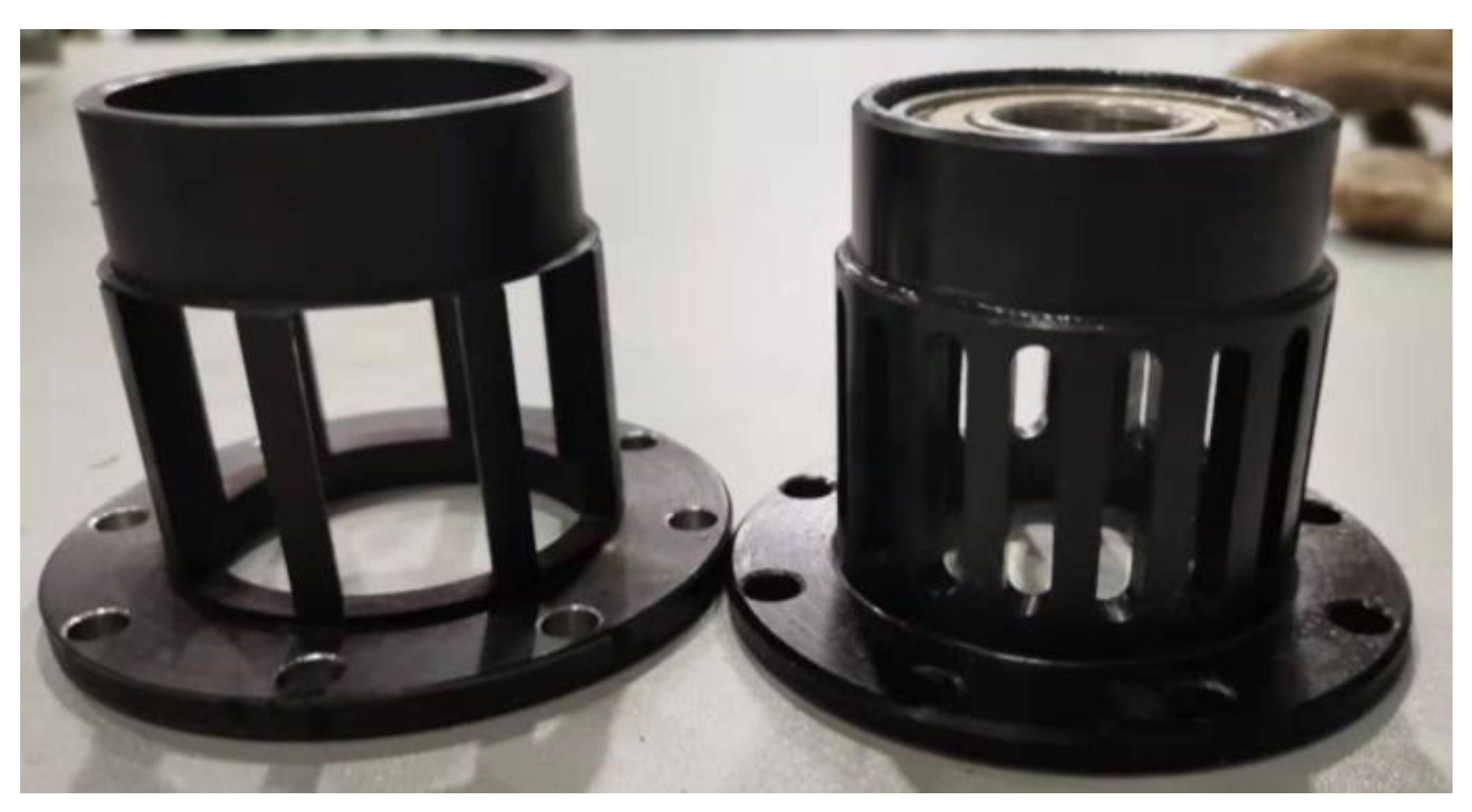
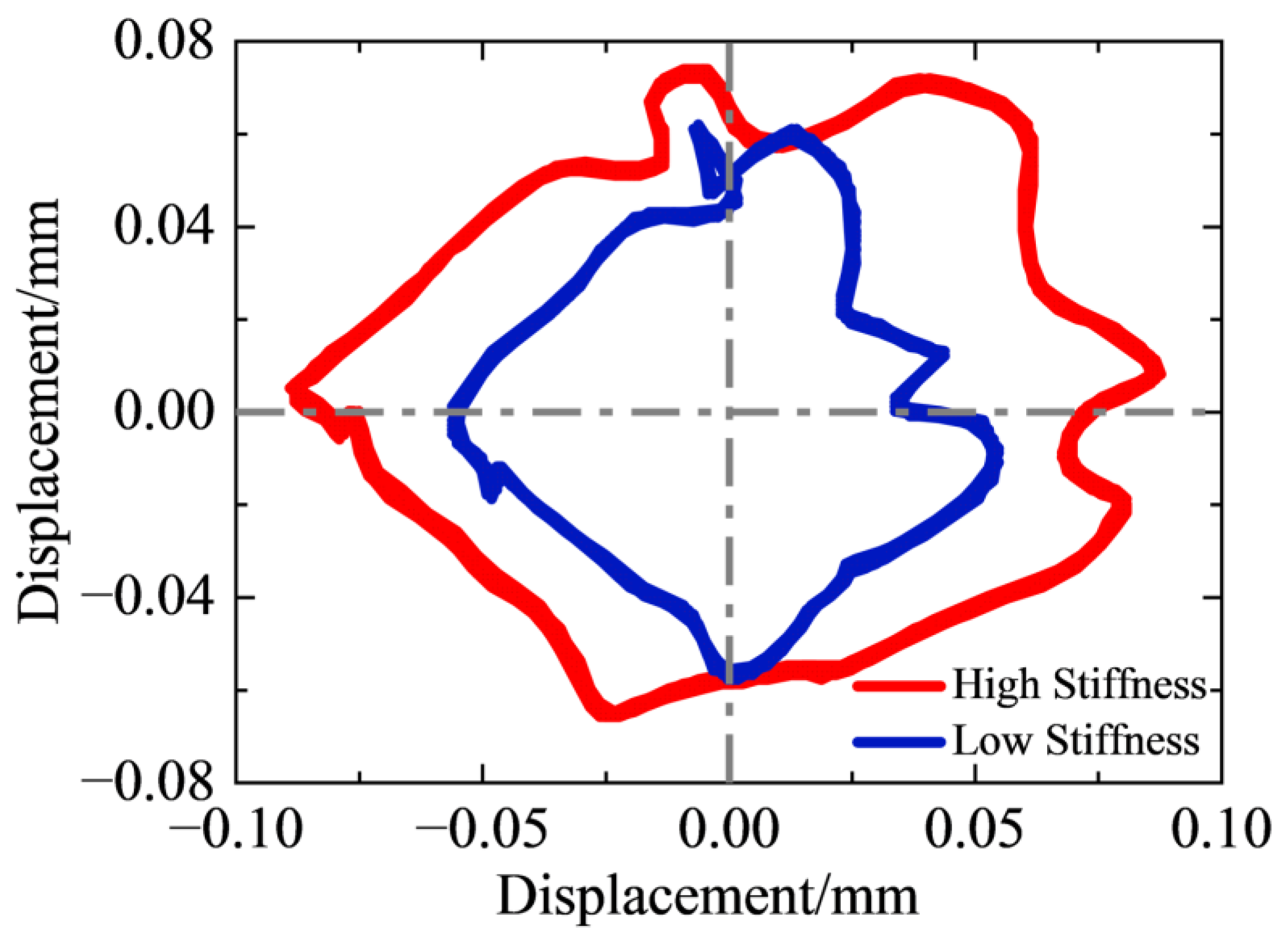
The cage-type elastic support of the squeeze film damper–elastic support system is modified, as shown in Figure 21, and the previous experimental steps are repeated to collect vibration signals at different stiffness levels;
(4)
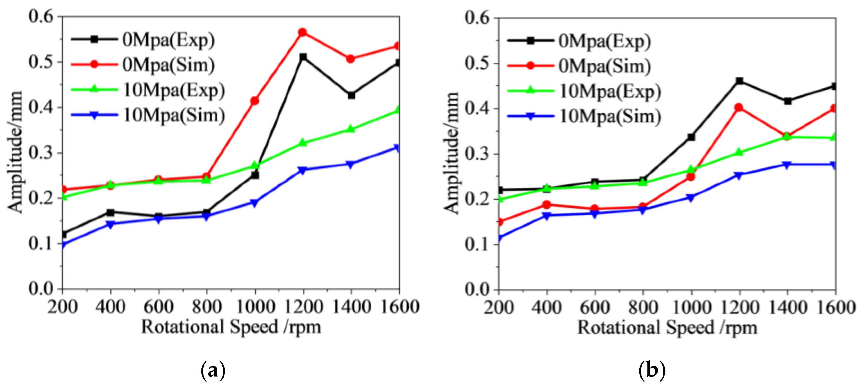
The oil pressure of the squeeze film damper–elastic support system is varied (0 to 10 MPa), and vibration signals are collected at different damping levels;
(5)
The experimental data are then organized.
As shown in Figure 22, the vibration response amplitude at the rotor’s center of mass increases with increasing stiffness. This is attributable to the test speed of 1500 rpm falling between the first critical speed and the second critical speed. Within this speed range, lower elastic support stiffness results in a smaller vibration response amplitude for the rotor with the SFD. It can also be seen from Figure 22 that the trajectory of the rotor is not elliptical, which may be due to the relatively light mass of the test rotor, amplifying the nonlinear effects of the rolling bearings. Moreover, the test point is located on the turntable at the center of mass of the rotor, which is affected by the machining accuracy and installation errors, and the rotor support may have misalignment errors, which together lead to the nonlinear characteristics of the motion trajectory.
As depicted in Figure 23, the damping of the combined support system demonstrably reduces the unbalance response amplitude. Furthermore, as the speed increases, the oil film pressure also rises, which in turn enhances the damping effect of the squeeze film damper on the rotor unbalance response. This indicates that the damping performance of the system is closely related to the operating speed.
Cross-referencing the findings from Figure 22 and Figure 23 reveals remarkable consistency between the experimental results and simulation outcomes. This alignment validates the combined support characteristics and vibration reduction methods presented in this paper and, to a degree, demonstrates the effectiveness of the dynamic modeling methods employed. The experimental data provides strong support for the reliability of our approach, reinforcing the significance of our findings in the context of rotor system dynamics.

4. Conclusions

This study presents a comprehensive dynamic modeling framework for aeroengine rotor systems, incorporating critical factors such as variable cross-section geometry, end-tooth coupling stiffness variations and combined support system excitations. By analyzing the unbalance response characteristics of complex discontinuous rotor support configurations and proposing theoretical vibration suppression strategies, this research provides a theoretical basis for optimizing rotor vibration control in high-speed aeroengine systems. Key findings are summarized as follow:
(1)
A robust dynamic model was established for aeroengine rotors with variable cross-sections, discrete support systems and end-tooth coupling-induced stiffness changes, forming the foundation for analyzing unbalance response mechanisms in discontinuous structures.
(2)
The axial positions of unbalance mass (1A, 1C, 2GT) were identified as highly sensitive to vibration characteristics, with phase angle differences between excitations directly affecting harmonic amplitude distributions. For instance, phase differences near 0° amplify the first and third harmonics while suppressing the second harmonic, whereas near 180° reduces the first and third harmonics and increases the second harmonic.
(3)
A practical vibration reduction framework was proposed, where support stiffness and damping are adjusted relative to operational speed. Stiffness maximization is recommended at speeds above 30,000 rpm, and UR1 (targeting 0–15,000 rpm), UR2 (15,000–50,000 rpm) and UR3 (50,000–80,000 rpm) are optimized for specific ranges, with damping enhancement further validated as an effective complement to stiffness control.

Author Contributions

Conceptualization, X.H.; Software, X.H.; Validation, H.Z. and K.L.; Formal analysis, X.H.; Investigation, H.Z. and K.L.; Resources, T.L.; Data curation, H.Z.; Writing—original draft, H.Z.; Writing—review & editing, T.L. and Q.W.; Supervision, A.W.; Project administration, A.W. and Q.W.; Funding acquisition, A.W. All authors have read and agreed to the published version of the manuscript.

Funding

This project was supported in part by the State Key Laboratory of Precision Manufacturing for Extreme Service Performance Foundation Project (No. ZZYJKT2021-07).

Data Availability Statement

The original contributions presented in the study are included in the article, further inquiries can be directed to the corresponding author.

Conflicts of Interest

Authors Haibiao Zhang and Kun Liu were employed by the company Hunan Aviation Powerplant Research Institute, AECC. The remaining authors declare that the research was conducted in the absence of any commercial or financial relationships that could be construed as a potential conflict of interest.

Nomenclature

α1Angle between the coordinate axes Zd and Z2α2Angle between the coordinate axes Xd and X2
RLi, RRiThe inner diameters of the left and right ends of the diskRLo, RRoInner diameters of the left and right ends of the disk
M d i s k o d , M d i s k i d Masses of the inner and outer disksMdMass of the turntable
U(xiyi)Step functionJdDiameter moment of inertia
h d Thickness of the diskJpPole moment of inertia
Xc, Yc, ZcDisk center of mass displacementeEccentric distance between center of mass and shape center
ΩRotation speedψInitial phase angle of disk mass center
LbLength of the blade along the Xb directionb1, b2Widths of the leaf root and tip positions along the Zb direction
h1, h2Thicknesses of the leaf root and tip positions along the Yb directionu, v, wDeformation on the tip of the blade in the Xb, Yb and Zb directions
ξDimensionless position of any point of the variable-section blade along the Xb directionηb, ηhTaper ratios of the variable cross-section blades along the Yb and Zb directions
A(ξ)Variable cross-section area of inertia of the bladeI(ξ)Variable cross-section moment of inertia of the blade
rQPosition vectors of any point on the bladex, y, zGeometric coordinates under the local coordinate system ObXbYbZb
Xdisk, Ydisk, ZdiskGeometric coordinates of the disk under the overall coordinate system OXYZrbOuter diameter of the disk at the blade connection position
Ai(i = 1,2,3,4,5)Transformation matrix between the coordinate systems OXYZ, OXdiskYdiskZdisk, OXrYrZr and ObXbYbZbβBlade mounting angle
TbladeKinetic energy for the rotating variable-section bladeρbDensity of the blade, denoting the kinetic energy without considering the torsional deformation of the rotating blade
T1, T2, T3Kinetic energy without considering the torsional deformation of the rotating bladeUbladePotential energy expression for blade
EbModulus of elasticity of the variable cross-section blade GbSshear modulus of the variable cross-section blade
κbShear factor of the variable cross-section blade fcCentrifugal force of the rotating blade
Tblade-diskKinetic energy for the blade–disk systemUblade-diskPotential energy for the blade–disk system
nbNumber of blades in the diskηOverall stiffness degradation correction coefficient of the circular arc end-teeth structure
η1, η2, η3Correction coefficients for interfacial contact area of the circular arc end-teeth, interfacial contact effect, and bending deformation of the rotor assembliesKcontactContact stiffness of circular arc end-teeth structure
K c o n t a c t p The contact stiffness of smooth interfaces of circular arc end-teeth structure under initial axial loadWcStrain energy of the circular arc end-teeth connection structure
FcNormal preload force EL, ERModulus of elasticity of the left and right end teeth
AcContact area of the end-teeth structure; bL, bRThickness of the left and right end teeth
bcThickness of the connecting region of the end-teethEequElastic modulus of the equivalent ring
ρ e q u Density of the equivalent ringμL, μREquivalent Poisson’s ratio of the left and right end teeth
εc, εhNormal strain and transverse strain of the circular arc end-teethμequPoisson’s ratio for the equivalent ring
μSFDViscosity of the oil filmRSFDRadius of the oil film
ϕ . Rotational angular velocity of the rotary axispPressure of the film
hThickness of the filmCSFDRadial clearance of the film
eSFDEccentric distance of the shaft neckεSFDEccentricity ratio of the shaft neck
LSFDLength of the oil filmMTSystem mass matrices
MrRotational inertia matricesCtDamping matrices of SFD
GGyroscopic matricesKStiffness matrices
FeUnbalance excitation forceFSFDSqueeze film force
qDisplacement vector C r Rayleigh damping matrices
α, βDamping coefficients of Rayleigh dampingε1, ε2Damping coefficient of the rotor system
ϕuPhase angles for each unitm(z)Magnitude of the unbalance
U(z)Unbalance vector

References

  1. Matsushita, O.; Tanaka, M.; Kanki, H.; Kobayashi, M.; Keogh, P. Vibrations of Rotating Machinery; Springer: Berlin/Heidelberg, Germany, 2017. [Google Scholar]
  2. Li, X.-Q.; Song, L.-K.; Bai, G.-C. Recent advances in reliability analysis of aeroengine rotor system: A review. Int. J. Struct. Integr. 2021, 13, 1–29. [Google Scholar] [CrossRef]
  3. Chen, G. Vibration modelling and verifications for whole aero-engine. J. Sound Vib. 2015, 349, 163–176. [Google Scholar] [CrossRef]
  4. Jin, M.; Wang, A.; Wang, Q.; Wang, L.; Ma, W. Dynamic Characteristics a Analysis of a New Type of Central Tie Rod Rotor-Blade-Bearing Coupling System Considering the End-Tooth Connection Structure. J. Mech. Eng. 2021, 57, 124–136. [Google Scholar]
  5. Jin, Y.; Lu, K.; Huang, C.; Hou, L.; Chen, Y. Nonlinear dynamic analysis of a complex dual rotor-bearing system based on a novel model reduction method. Appl. Math. Model. 2019, 75, 553–571. [Google Scholar] [CrossRef]
  6. Tarkashvand, A.; Golmohammadi, A.; Safizadeh, M.S. Stability and modal analysis of an unbalanced asymmetric multi-disk rotor system on bearings as viscoelastic substrate. Arch. Appl. Mech. 2022, 92, 2247–2271. [Google Scholar] [CrossRef]
  7. Yang, Y.; Yao, M.; Niu, Y.; Wu, Q.; Wang, C. Model verification and vibration analysis of the four-disk hollow flexible shaft rotor system. Int. J. Mech. Sci. 2024, 268, 109051. [Google Scholar] [CrossRef]
  8. Bonello, P.; Hai, P.M. Computational Studies of the Unbalance Response of a Whole Aero-Engine Model with Squeeze-Film Bearings. J. Eng. Gas Turbines Power 2009, 132, 032504. [Google Scholar] [CrossRef]
  9. Ma, P.; Zhai, J.; Wang, Z.; Zhang, H.; Han, Q. Unbalance Vibration Characteristics and Sensitivity Analysis of the Dual-Rotor System in Aeroengines. J. Aerosp. Eng. 2021, 34, 04020094. [Google Scholar] [CrossRef]
  10. He, J.; Jiang, D.; Zhang, D.; Tang, Z.; Fei, Q. Model updating of rotor system based on the adaptive Gaussian process model using unbalance response. J. Sound Vib. 2024, 571, 118006. [Google Scholar] [CrossRef]
  11. Yang, W.; Liang, M.; Wang, L.; Yuan, H. Research on unbalance response characteristics of gas turbine blade-disk rotor system. J. Vibroeng. 2018, 20, 1676–1690. [Google Scholar] [CrossRef]
  12. Chen, X.; Zhai, J.; Zhang, H.; Han, Q. Simulation study on unbalance vibration characteristics of dual-rotor system. SN Appl. Sci. 2020, 2, 1423. [Google Scholar] [CrossRef]
  13. Song, L.; Chen, Y. A Prediction Model of Two-Sided Unbalance in the Multi-Stage Assembled Rotor of an Aero Engine. Machines 2024, 12, 503. [Google Scholar] [CrossRef]
  14. Chen, Y.; Cui, J.; Sun, X. An Unbalance Optimization Method for a Multi-Stage Rotor Based on an Assembly Error Propagation Model. Appl. Sci. 2021, 11, 887. [Google Scholar] [CrossRef]
  15. Cruz, W.; Arzola, N.; Araque, O. Modeling and experimental validation of the vibration in an unbalance multi-stage rotor. J. Mech. Eng. Sci. 2019, 13, 5703–5716. [Google Scholar] [CrossRef]
  16. Hong, J.; Li, T.; Liang, Z.; Zhang, D.; Ma, Y.; Wang, Y. Safety Design Methods for Rotor-Bearing System and Dynamic Analysis in Aero-Engines. In Proceedings of the ASME Turbo Expo 2018: Turbomachinery Technical Conference and Exposition, Oslo, Norway, 11–15 June 2018. [Google Scholar]
  17. Yao, J.; Liu, L.; Yang, F.; Scarpa, F.; Gao, J. Identification and optimization of unbalance parameters in rotor-bearing systems. J. Sound Vib. 2018, 431, 54–69. [Google Scholar] [CrossRef]
  18. Wang, L.; Wang, A.; Jin, M.; Huang, Q.; Yin, Y. Nonlinear effects of induced unbalance in the rod fastening rotor-bearing system considering nonlinear contact. Arch. Appl. Mech. 2020, 90, 917–943. [Google Scholar] [CrossRef]
  19. Guskov, M.; Gibert, C.; Sanchez, L.; Thouverez, F. Unbalance response of a dual shaft test rig with a squeeze film damper: Design, prediction and experiment. In Proceedings of the CFM 2009-19ème Congrès Français de Mécanique, Marseille, France, 24–28 October 2009. [Google Scholar]
  20. Qin, W.; Zhang, J.; Wang, H.; Ren, X. Response and Bifurcation of Rotor with Squeeze Film Damper Supported on Elastic Foundation. J. Northwest. Polytech. Univ. 2006, 24, 245–248. [Google Scholar]
  21. He, W.; Pan, B.; Bai, J. Transient response analysis of squeezed film damper rotor system under sudden unbalance load. Gas Turbine Exp. Res. 2020, 33, 36–40. [Google Scholar]
  22. Sun, K.; Luo, Z.; Li, L.; Ge, X.; Zheng, S. Assembly Characteristics and Experimental Study of Rotor System with Elastic Ring Squeeze Film Damper. J. Mech. Eng. 2023, 59, 118–131. [Google Scholar]
  23. Li, B.; Cheng, D.; Jiang, Z. Experiment study on dynamic characteristics of elastic ring squeeze film damper rotor system. Gas Turbine Exp. Res. 2015, 28, 19–22. [Google Scholar]
  24. Nie, W.; Yang, X.; Deng, W.; Tang, H. Vibration Optimization Design and Experiment for Support of Aeroengine High-Speed Rotor System. In International Conference on Mechanical System Dynamics; Springer Nature Singapore: Singapore, 2023; pp. 1413–1424. [Google Scholar]
  25. Tichy, J.A. Behavior of a squeeze film damper with an electrorheological fluid. Tribol. Trans. 1993, 36, 127–133. [Google Scholar] [CrossRef]
  26. Jin, M.; Wang, A.; Wang, Q.; Ying, Y.; Heng, X.; Zhang, H. Dynamic characteristics analysis of the complex rotor-blade system for the aero-turboshaft engine. J. Aerosp. Power 2024, 39, 66–82. [Google Scholar] [CrossRef]
  27. Xing, Y.; Liu, B.; Liu, G. A differential quadrature finite element method. Int. J. Appl. Mech. 2010, 2, 207–227. [Google Scholar] [CrossRef]
  28. Zhang, H.; Li, Z.; Liu, H.; Liu, T.; Wang, Q. Modeling and Dynamic Analysis of Double-Row Angular Contact Ball Bearing–Rotor–Disk System. Lubricants 2024, 12, 441. [Google Scholar] [CrossRef]
Figure 1. Schematic diagram of the gas generator rotor system.
Lubricants 13 00266 g001
Figure 2. Schematic diagram of hollow rigid disk.
Lubricants 13 00266 g002
Figure 3. Schematic diagram of variable cross-section blade.
Lubricants 13 00266 g003
Figure 4. Schematic diagram of the disk–blade coupling system.
Lubricants 13 00266 g004
Figure 5. The equivalent model of the circular arc end-teeth connection structures.
Lubricants 13 00266 g005
Figure 6. The equivalent model of end-teeth connection structures in the aeroengine rotor system.
Lubricants 13 00266 g006
Figure 7. Model of the SFD support system. (a) The model of elastic support, (b) the mechanical model of the squeeze film.
Lubricants 13 00266 g007
Figure 8. The DQFEM model of the complex variable cross-section discontinuous rotor support system.
Lubricants 13 00266 g008
Figure 9. Schematic diagram of the axial position distribution of unbalance mass in the aeroengine rotor.
Lubricants 13 00266 g009
Figure 10. Vibration response caused by unbalance excitations at different axial positions.
Lubricants 13 00266 g010
Figure 11. Vibration modes of the aeroengine rotor.
Lubricants 13 00266 g011
Figure 12. Schematic diagram of circumferential positions of unbalance mass in aeroengine rotor.
Lubricants 13 00266 g012
Figure 13. Vibration responses under different circumferential distributions of unbalance mass of rotor.
Lubricants 13 00266 g013
Figure 14. Vibration response of the rotor support system with asqueeze film damper under the three different unbalance distribution methods.
Lubricants 13 00266 g014
Figure 15. Vibration response of the rotor support system with the support stiffnesses K1, K2 and K3.
Lubricants 13 00266 g015
Figure 16. Vibration response of the rotor support system with the damping C1 and C2.
Lubricants 13 00266 g016
Figure 17. Test bench of the discontinuous rotor support system.
Lubricants 13 00266 g017
Figure 18. Different distribution of unbalance mass of the test rotor system. (a) U0, (b) U1, (c) U2, (d) the mass of standard screws and weight blocks.
Lubricants 13 00266 g018
Figure 19. Unbalance response amplitudes of test rotor systems at the first three critical speeds under three types of position distributions of the unbalance mass.
Lubricants 13 00266 g019
Figure 20. Unbalance responses of test rotor systems at 1500 rpm under three types of position distributions of the unbalance mass.
Lubricants 13 00266 g020
Figure 21. Cage-type elastic supports with different stiffnesses.
Lubricants 13 00266 g021
Figure 22. Unbalance response displacement of rotor systems with different elastic support stiffnesses at 1500 rpm.
Lubricants 13 00266 g022
Figure 23. Unbalance response amplitude of rotor systems with SFD at different oil film pressures. (a) Unbalance response amplitude of the middle disc, (b) unbalance response amplitude of the left disc.
Lubricants 13 00266 g023
Table 1. The parameters of the equivalent model of six end-teeth coupling structures.
NameEquivalent Elastic Modulus (Gpa)Equivalent Density (kg/m3)Poisson’s Ratio
C173.804401.070.3
C268.644347.210.3
C372.934366.700.3
C4155.766130.610.3
C5220.387906.390.3
C6211.667886.850.3
Table 2. The influence of different axial distributions on the first three critical speeds and amplitudes of rotors.
OrderParameter1A2A3A1C1GT2GT
1stSpeed (rpm)11,25011,20011,20011,20011,20011,200
Amplitude (mm)0.0760.1000.1010.1250.1400.143
2ndSpeed (rpm)23,90023,95023,95024,05023,90023,900
Amplitude (mm)1.150.9140.7370.2270.2870.527
3rdSpeed (rpm)71,900------70,800---68,300
Amplitude (mm)0.631------0.366---0.291
Table 3. The influence of different circumferential distributions on the first three critical speeds and amplitudes of rotors.
OrderParameter030°60°90°120°150°180°
1stSpeed (rpm)10,95011,05011,20011,20011,20011,25011,300
Amplitude (mm)0.2650.2570.2360.2040.1630.1240.104
2ndSpeed (rpm)23,90024,00024,00023,85023,85023,70023,900
Amplitude (mm)0.0700.0970.1290.1540.1700.1730.167
3rdSpeed (rpm)70,16070,00069,95069,85069,25068,850---
Amplitude (mm)0.2320.2250.2040.1690.1240.075---
Table 4. Three different positions of the unbalance mass of three vibration reduction methods.
Name1A1C2GT
MassPhaseMassPhaseMassPhase
UR 10012 g00
UR 26 g006 g
UR 36 g006 g180°
Disclaimer/Publisher’s Note: The statements, opinions and data contained in all publications are solely those of the individual author(s) and contributor(s) and not of MDPI and/or the editor(s). MDPI and/or the editor(s) disclaim responsibility for any injury to people or property resulting from any ideas, methods, instructions or products referred to in the content.

