Article

Design and Analysis of a Lower Limb Rehabilitation Training Component for Bedridden Stroke Patients

1
Academy for Engineering & Technology, Fudan University, Shanghai 200433, China
2
Shanghai Clinical Research Center for Aging and Medicine, Shanghai 200040, China
3
Faculty of Mechanical Engineering & Mechanics, Ningbo University, Ningbo 315211, China
4
Parallel Robot and Mechatronic System Laboratory of Hebei Province, Yanshan University, Qinhuangdao 066004, China
*
Authors to whom correspondence should be addressed.
Machines 2021, 9(10), 224; https://doi.org/10.3390/machines9100224
Submission received: 24 August 2021 / Revised: 24 September 2021 / Accepted: 28 September 2021 / Published: 30 September 2021
(This article belongs to the Special Issue Design and Control of Advanced Mechatronics Systems)

Abstract

:
Carrying out the immediate rehabilitation interventional therapy will better improve the curative effect of rehabilitation therapy, after the condition of bedridden stroke patients becomes stable. A new lower limb rehabilitation training module, as a component of a synchronous rehabilitation robot for bedridden stroke patients’ upper and lower limbs, is proposed. It can electrically adjust the body shape of patients with a different weight and height. Firstly, the innovative mechanism design of the lower limb rehabilitation training module is studied. Then, the mechanism of the lower limb rehabilitation module is simplified and the geometric relationship of the human–machine linkage mechanism is deduced. Next, the trajectory planning and dynamic modeling of the human–machine linkage mechanism are carried out. Based on the analysis of the static moment safety protection of the human–machine linkage model, the motor driving force required in the rehabilitation process is calculated to achieve the purpose of rationalizing the rehabilitation movement of the patient’s lower limb. To reconstruct the patient’s motor functions, an active training control strategy based on the sandy soil model is proposed. Finally, the experimental platform of the proposed robot is constructed, and the preliminary physical experiment proves the feasibility of the lower limb rehabilitation component.

1. Introduction

There are currently 13 million cerebral apoplexy patients living with diseases in China, and about 2 million new cerebral apoplexy patients every year. The disability rate of survivors is 75%, and has become the leading cause of disability in the adult population [1]. In addition, other neurological diseases also lead to movement impairment of the upper and lower limbs, such as spinal cord injury [2]. Patients with limb dysfunctions are unable to complete the basic movements in daily life due to the lack of fine control of the limb muscles [3]. Meanwhile, the muscle mass of patients’ limbs in the initial stroke stage is reduced by about 1.6% each day. Carrying out immediate rehabilitation interventional therapy will better improve the curative effect of rehabilitation therapy and overcome some secondary complications of stroke-related neurological diseases, after the condition of bedridden stroke patients becomes stable [4]. Due to the imbalance of the rehabilitation physician–patient ratio in China, it is difficult for bedridden stroke patients to carry out timely and standardized rehabilitation treatment, and it is difficult to ensure a certain period of rehabilitation training, which will result in the serious sequelae of patients [5]. The effect of a rehabilitation training robot in helping patients is very remarkable [6,7,8]. It not only improves the basic function of limbs with impaired motor function, but also reduces the possibility of the patient developing a permanent disability [9,10]. However, most of rehabilitation robots mainly focus on the affected limbs of patients. For bedridden stroke patients, their motor function shows symptoms such as limb weakness, poor balance and uncoordinated movements. The uncoordinated and asymmetric motor function of the upper and lower limbs also inhibits the recovery process of human limb motor function [11]. Therefore, there is a contradiction between the synchronous movement of upper and lower limbs and the abnormal coupling of nerves. Moreover, there is often a contradiction between bed rest and body balance training for bedridden stroke patients. Based on the mechanism of compatibility design and human–computer interaction, a new synchronous rehabilitation robot for the upper and lower limbs is studied in this paper, as shown in Figure 1. The proposed synchronous rehabilitation robot in this paper includes a lower limb rehabilitation module, upper limb rehabilitation module and multi-posture bed support module.
This paper focuses on the research of the lower limb rehabilitation module. In terms of how the robot interacts with the patient’s lower limb, the lower limb rehabilitation training system (LLRTS) can be divided into two types: the exoskeleton ULRR [12,13] and the end-traction ULRR. The exoskeleton ULRR can drive each lower limb joint through the independent movement of multiple driving joints [14]. However, most of the exoskeleton type ULRRs adapt to a serial mechanism structure with a high cost of manufacture. Due to the outstanding advantages of a simple mechanism, good motion flexibility and low cost, the end-traction ULRR is a research hotspot. According to the training posture of patients, the LLRTS for stroke patients can be divided into the standing type LLRTS [15,16], sitting-lying type LLRTS [17,18] and multi-posture type LLRTS [19,20]. Locomat, as a typical standing type LLRTS, with the help of the patient bodyweight support system, can accurately match the speed of the mechanical leg with the speed of a treadmill, which can assist patients with hip, knee and ankle joint movements to receive natural gait training [21,22]. The patients’ lower limbs can restore their natural gait through a single-degree-of-freedom, mechanized gait trainer with four, six and eight bars, introduced from the perspective of kinematics [23]. However, the standing type LLRTS is suitable for the middle- and late-stage rehabilitation of patients with walking ability. As a supplement training device of the standing type LLRTS, the sitting-lying type LLRTS is mostly used in the early stage of rehabilitation when the lower limb muscle strength of stroke patients is relatively weak. The sitting-lying type LLRTS, such as MotionMaker, can let patients sit on a chair and adopt different training modes at a patient’s different rehabilitation stages. The length of the mechanical leg and the width between the two legs can be adjusted to adapt to patients with different heights and shapes [24,25,26]. The multi-posture LLRTS combines the advantages of the sitting-lying type and the standing type LLRTS, and can realize the posture transformation from the lying to standing posture. Erigo, developed by the University in Switzerland, adds a passive training strategy on the basis of inclined standing training to realize the flexion and extension movement of human hip joint, knee joint and ankle joint [27]. The Flexbot, made in China, can realize the gait training in multiple postures. It can overcome various physiological problems caused by long-term bed rest [28]. The multi-posture LLRTS is characterized by assisting simple passive training, which is especially suitable for the recovery training of the basic abilities of early bedridden patients.
It is very necessary to ensure the absolute safety of patients during the training. Combined with the mechanism design advantage of the lower limb rehabilitation training systems from the above remarkable studies, the proposed lower limb rehabilitation module can also electrically adjust the body shape of patients with a different weight and height. Meanwhile, the innovative design of the weight reduction mechanism can overcome the weight of human lower limb fixation component during a patient’s training. This paper is organized as follows: Firstly, the motion gait of human lower limb during walking is analyzed. Then, the mechanism of the lower limb rehabilitation module is designed and simplified, the geometric relationship of the structure is deduced, the trajectory planning and dynamic modeling of the module are carried out, and then the motor driving force required in the rehabilitation process is calculated to achieve the purpose of rationalizing the rehabilitation movement of the lower limb.

2. Materials and Methods

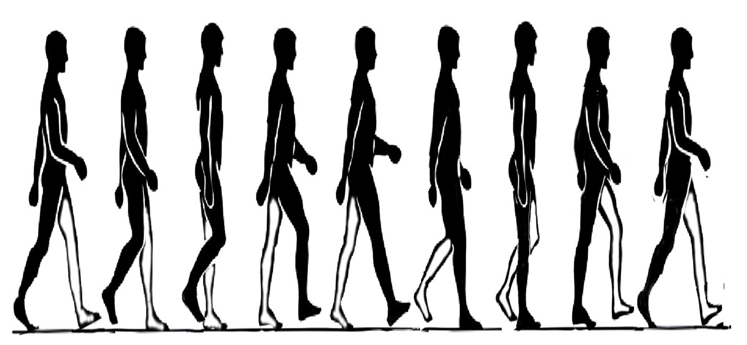
2.1. Motion Analysis of Human Lower Limb during Walking

For the lower limbs of the human body, walking, running and ascending and descending stairs are the main forms of movement which play a vital role in the rehabilitation of patients and their reintegration into society, while these different forms of human movement are realized by walking. Therefore, it is very important for the mechanism design of LLRTS to analyze the specific movements of hip, knee and ankle during walking. The hip joint plays a major role in walking, the knee joint plays a role in control, cushioning and stability, and the ankle joint regulates the contact of the foot with the ground. The human walking process is shown in Figure 2. The characteristic parameters of the human gait mainly include the gait cycle, step length, step width, walking height, gait speed, step frequency and so on. The related parameters are studied in the literature [29], shown in Table 1.
A person’s gait cycle is divided into a swing period and support period. Swing period refers to the time from one tiptoe off the ground to the foot heel reaching the ground, accounting for about 40% of the whole gait cycle. Support period refers to the time when the feet support the human body, accounting for about 60% of the gait cycle. The support period can be divided into single support period and double support period. Single support period refers to the time when the sole of one side of the foot contacts the ground, that is, the interval between one side of the foot heel reaching the ground and lifting the toe off the ground; double support period refers to the time when both feet are in contact with the ground at the same time. When the human step speed increases, the proportion of support period decreases and the proportion of swing period increases. Meanwhile, during walking the patient’s weak balance and muscle strength in the early stroke stage require the use of body support devices, including slings or backrest beds.

2.2. Mechanism Design and Analysis of Lower Limb Rehabilitation Module

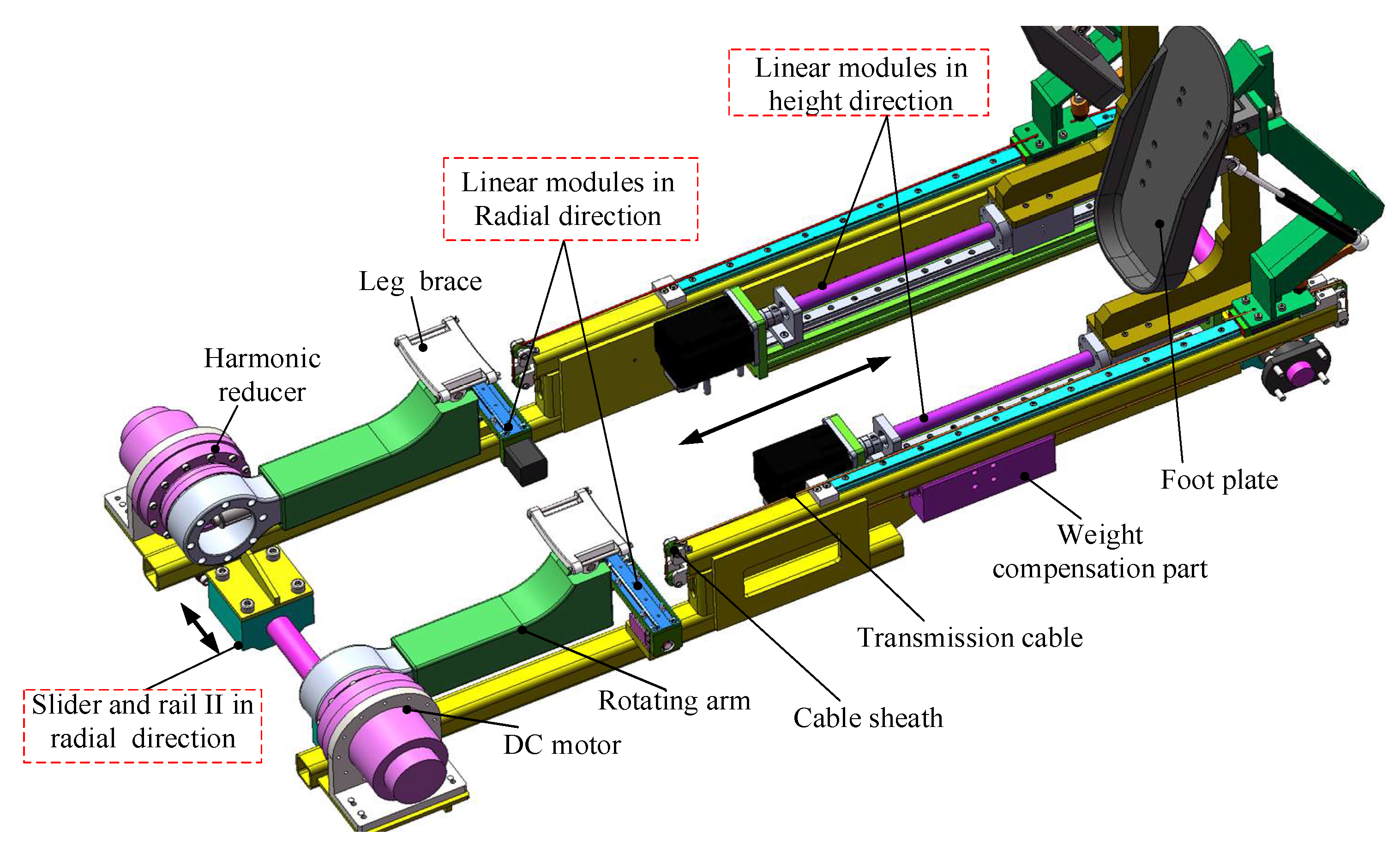
2.2.1. Mechanism Design of Lower Limb Rehabilitation Module

The lower limb rehabilitation module is designed on the basis of the human basic walking movement model. The purpose is to drive the patient’s lower limbs to safely and effectively complete standardized rehabilitation movements. The lower limb rehabilitation module mainly includes two parts, the somatotype electric adjustment module and the rehabilitation training module. The somatotype electric adjustment module, as shown in Figure 3, is composed of four linear modules, and the linear modules in radial direction are perpendicular to the linear modules in height direction. Its main function is to adjust the length and width of the rehabilitation training module according to the shape of the human body.
The rehabilitation training module includes a hip movement module, an ankle movement module and a frame support module. The hip movement module, as shown in Figure 3, is composed of a DC motor, a harmonic drive/reduction, rotating arm and leg brace. A linear guide rail and slider are installed on the rotating arm, and a leg brace is installed on the linear guide rail, which will be connected to the human thigh through the leg brace. The movement and torque of the DC motor is transmitted to the human thigh through the combination of the harmonic drive/reduction and the rotating arm to realize the rotating movement of the human hip joint.
Through the analysis of the mechanical structure of the above-mentioned lower limb rehabilitation module with the human lower limb, a simplified diagram of the human–machine rigid body linkage model can be obtained as shown in Figure 4. Since the length of the human thigh is greater than the length of the calf, the human–machine rigid link mechanism OAB in Figure 4 is a rocker slider mechanism. Therefore, the main function of the ankle movement module is to aid the driven degrees of freedom of ankle motion to meet the foot movement needs of patients during lower limb rehabilitation exercises. In order to ensure the comfort of patients’ rehabilitation training and reduce the self-weight impact of the ankle movement module on patients’ lower limbs, a weight compensation mechanism of ankle motion module is also designed, including the weight compensation part, guide rail, slider, transmission cable and cable sheath, and the foot plate, as shown in Figure 3. The weight compensation part is installed on the slider, and one end of slider is fixed with the transmission cable. After passing through the cable sheath, the transmission cable is fixed with the foot plate. Therefore, the weight compensation part will balance the gravity of the ankle movement module, which can make the patient’s feet feel more comfortable when participating in the training.

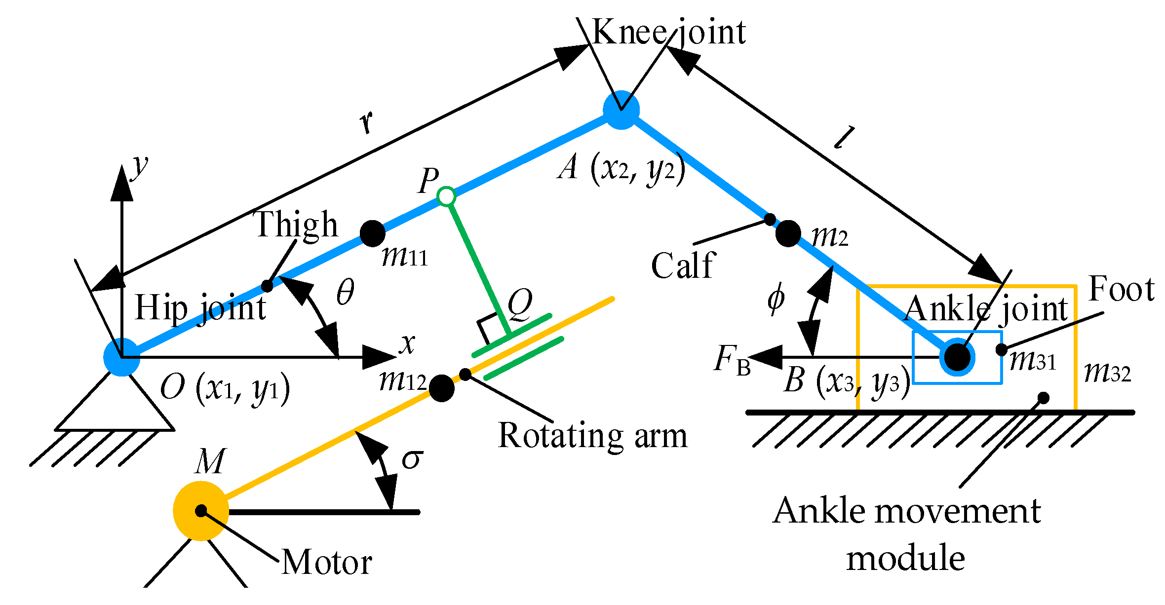
2.2.2. Analysis of Human–Machine Simplified Linkage Model

In Figure 4, the points O, M and Q are the hip joint, driving motor and rotating hinge, respectively. Linkage MQ is the rotating arm, which is perpendicular to the linkage PQ. Additionally, there is a moving pair between the linkage MQ and linkage PQ. The points O, P, Q, M will form a four-bar linkage, and the geometric relationship between the motion angle θ of hip joint and the motion angle σ of connecting rod can be calculated very simply. As the designed rehabilitation robot is a bed-based rehabilitation robot, the centers of the patient’s ankle and hip joints can be located approximately on the same straight line when the patient is lying on the bed, so the mechanism can be simplified into a centripetal rocker slider mechanism. The rocker bar OA is the original driving part, linkage AB is the intermediate link, and the slider B is the driven part. The coordinate system O-xy is established with O as the origin; r and l are the lengths of rods OA and AB, angle θ is the rotation angle of thigh OA, angle ϕ is the angle between rod AB and the x axis. The coordinates of points O, A and B are (x1, y1), (x2, y2) and (x3, y3), respectively. The masses of linkage OA, AB of the slider are m1, m2, and m3, respectively. The mass of m1 is composed of two parts, the weight of the human thigh m11 and the weight of the driving connecting rod m12, and the weight of m2 is the human calf. The weight of m3 is also composed of two parts, the weight of the human foot m31 and the weight of the pedal m32.
Based on the coordinates of the linkage OA, linkage AB, and the centroid of the slider B, the relationship between the coordinate of point B, angle θ and angle ϕ are obtained as follows:
{ x 3 = r cos θ + l cos ϕ r sin θ = l sin ϕ ,
When performing rehabilitation training on the patient, the movement of the patient’s ankle joint axis is also very worthy of study, so the relationship between the displacement x3 and the rotation angle θ needs to be calculated:
x 3 = r cos θ + l 1 ( r l ) 2 sin 2 θ ,

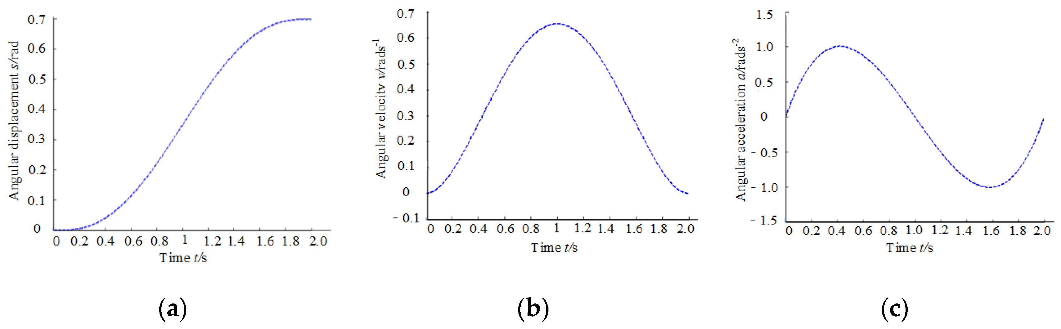
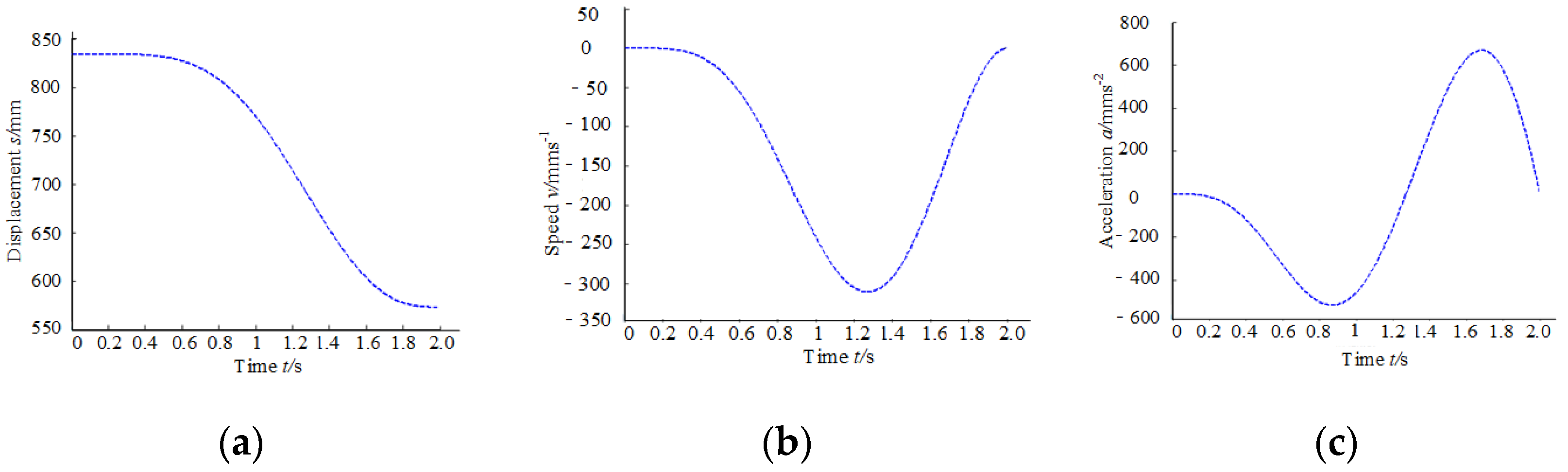
2.2.3. Design and Analysis of Speed and Acceleration of Human–Machine Linkage Model

In order to avoid the impact caused by sudden changes in speed and acceleration during the rehabilitation training of the patient, which affect the patient’s training experience, it is necessary to plan a smooth and continuous speed and acceleration trajectory. Based on the design requirements [30], the lower limbs stepping speed of the rehabilitation robot is adjustable from 20 to 60 steps/min, and the angle range of hip joint θ ( t ) is 0 to 40°, and the comfort of the patient during training is considered comprehensively. A quintic polynomial to plan the trajectory is adopted:
θ ( t ) = a 0 + a 1 t + a 2 t 2 + a 3 t 3 + a 4 t 4 + a 5 t 5 ,
The starting training position, end training position, starting training speed, end training speed, starting acceleration and end acceleration of the rehabilitation robot’s training trajectory is set in Equation (4):
{ θ ( 0 ) = θ · ( 0 ) = θ · ( 2 ) = θ · · ( 0 ) = θ · · ( 2 ) = 0 θ ( 2 ) = 2 9 π ,
Substituting the above initial and final constraint conditions of the trajectory into Equation (3), the quintic polynomial can be solved. The displacement, velocity and acceleration of the hip joint can be obtained as shown in Figure 5. From the analysis of the curves in Figure 5, it can be seen that the obtained angular displacement curve, angular velocity curve, and angular acceleration curve of the hip joint are continuous and smooth, and there is no impact due to sudden changes in speed or acceleration, which ensures the comfort of the patient during the rehabilitation process.
The length of the thigh is 402~505 mm, and the length of the calf is 313~403 mm [20]. Then, r = 465 mm and l = 369 mm are selected as the human body size data. The simulation curves of the axis of the ankle joint can be obtained as shown in Figure 6.

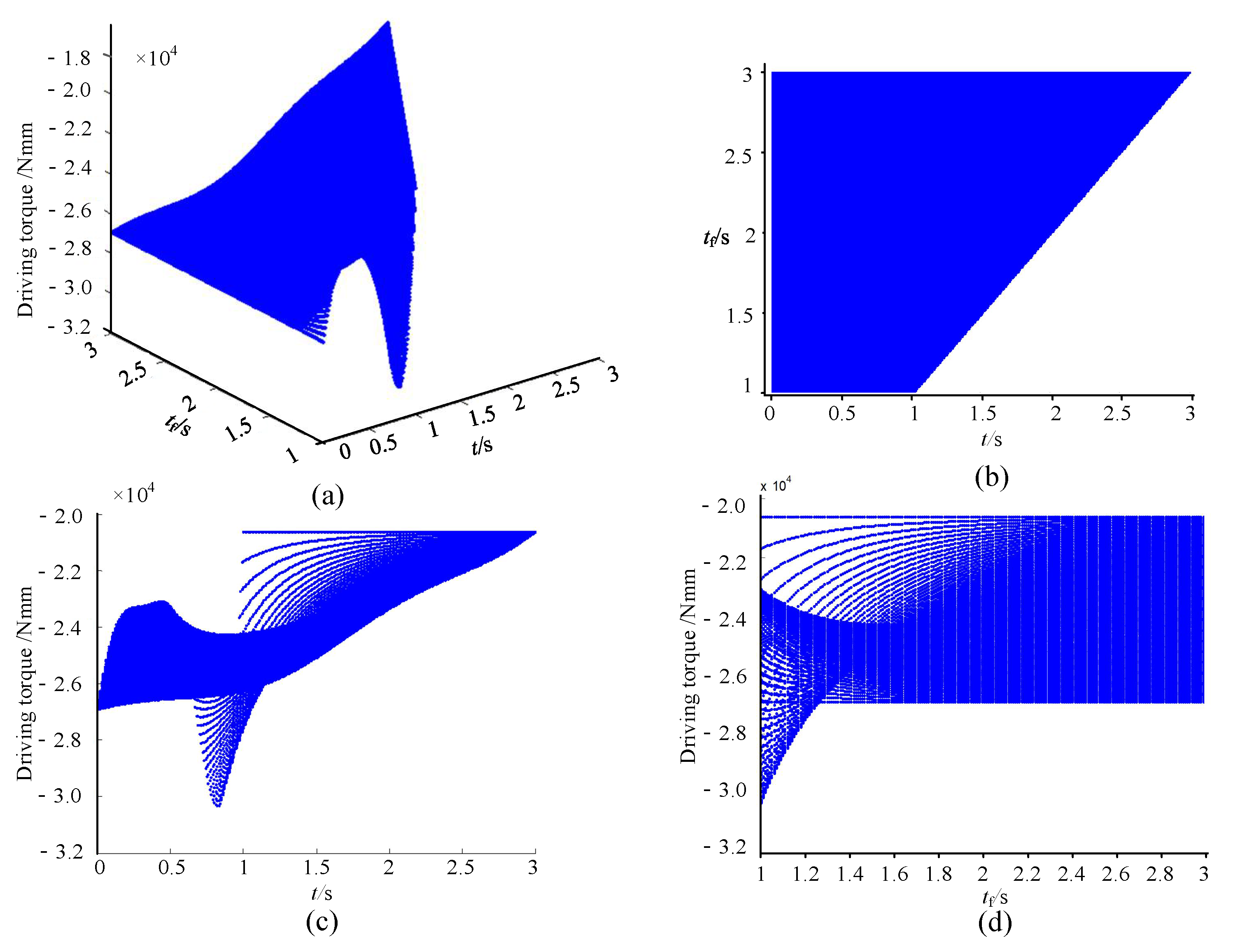
2.2.4. Dynamic Analysis of Lower Limb Rehabilitation Module

The term τ is the torque of the motor, and FB is the friction force on the slider. The kinetic energy of the rocker, the connecting rod and the slider can be obtained, and the total kinetic energy of the human–machine linkage model can be obtained:
T = T 1 + T 2 + T 3 = 1 6 m 1 r 2 θ · 2 + 1 6 m 2 l 2 ϕ · 2 + 1 2 m 2 r 2 θ · 2 sin 2 θ + 1 2 m 2 r l θ · ϕ · sin θ sin ϕ + 1 2 m 3 r 2 θ · 2 sin 2 θ + m 3 r l θ · ϕ · sin θ sin ϕ + 1 2 m 3 l 2 ϕ · 2 sin 2 ϕ
where, T 1 , T 2 and T 3 represents the kinetic energy of the linkage OB, linkage AB and the slider B.
The total gravitational potential energy of the proposed human–machine linkage model is obtained:
W = W 1 + W 2 + W 3 = 1 2 m 1 g r sin θ + 1 2 m 2 g l sin ϕ ,
where, W 1 , W 2 and W 3 represent the gravitational potential energy of the linkage OB, linkage AB and the slider B.
In order to facilitate subsequent formula writing, define:
c = l 2 r 2 sin 2 θ
The total is then applied by the motor and friction force can be obtained by:
δ W = ( τ F B r sin θ ( 1 + r c cos θ ) ) δ θ ,
By referring to the product manual of HIWIN Technologies Corp. (www.hiwin.tw, accessed on 20 June 2012), the formula for calculating the frictional of the linear guideway can be obtained as shown below:
F B = μ × W + S ,
where FB is the friction (N), S is the friction resistance (N), μ is the coefficient of friction, and W is the normal load (N).
Then, the kinetic equation can be obtained:
M ( θ ) θ · · + B ( θ ) θ · 2 + G ( θ ) = τ T F B ,
where:
{ M ( θ ) = [ ( 2 m 3 + m 2 ) + m 3 c r cos θ ] ( r 3 c cos θ sin 2 θ ) + ( m 2 + m 3 ) r 2 sin 2 θ + 1 3 m 2 ( l c ) 2 ( r cos θ ) 2 + 1 3 m 1 r 2 B ( θ ) = m 2 r 2 sin θ cos θ [ 1 l 3 c 2 + r c cos θ + ( l r ) 2 3 c 4 cos 2 θ + r 3 2 c 3 cos θ sin 2 θ ] m 2 r 3 2 c sin 3 θ m 3 r 3 c sin 3 θ + m 3 r 2 sin θ cos θ [ 1 r 2 c 2 sin 2 θ + r 2 c 2 cos 2 θ + 2 r c cos θ + r 3 c 3 sin 2 θ cos θ ] G ( θ ) = 1 2 ( m 1 + m 2 ) g r cos θ T F B = F B r sin θ ( 1 + r l 2 r 2 sin 2 θ cos θ )
The weight m12 of the driving connecting rod can be obtained by adding 1060 aluminum and 45 steel in simulation software, which equals 1.166 kg, and in the same way, m32 = 0.977 kg is also obtained. Then, set m1 = 9.3698 kg, m2 = 2.4294 kg, m3 = 1.7906 kg, r = 465 mm, and l = 369 mm. Through Equation (9), it can be seen that when the patient’s rehabilitation speed is different due to the existence of inertial force, the required motor driving force is different, so it is necessary to calculate the motor driving force required by the patient at different speeds due to the design of the rehabilitation robot. The requirement is that the stepping speed of the lower limbs is 20–60 steps/min. In order to reduce the impact on the rehabilitation of patients, it is important to continue to plan the trajectory of the lower limb rehabilitation with a fifth-order polynomial, similar to Equation (5). The time adjustment factor is set as tf, which equals 1~3 s. The angular driving function of the hip joint can be obtained:
θ ( t ) = 20 π 9 ( t t f ) 3 10 π 3 ( t t f ) 4 + 4 π 3 ( t t f ) 5 ,
The above-mentioned relevant parameters are imported into the simulation software and the driving torque curve of the robot can be obtained as shown in Figure 7.
By analyzing the variation range of the motor driving torque required to drive the patient’s hip joint within the time range of tf = 1~3 s and t = 1~3 s, the maximum motor driving torque calculated in the simulation software is 30,200 N.mm, which provides a basis for motor selection of the prototype.

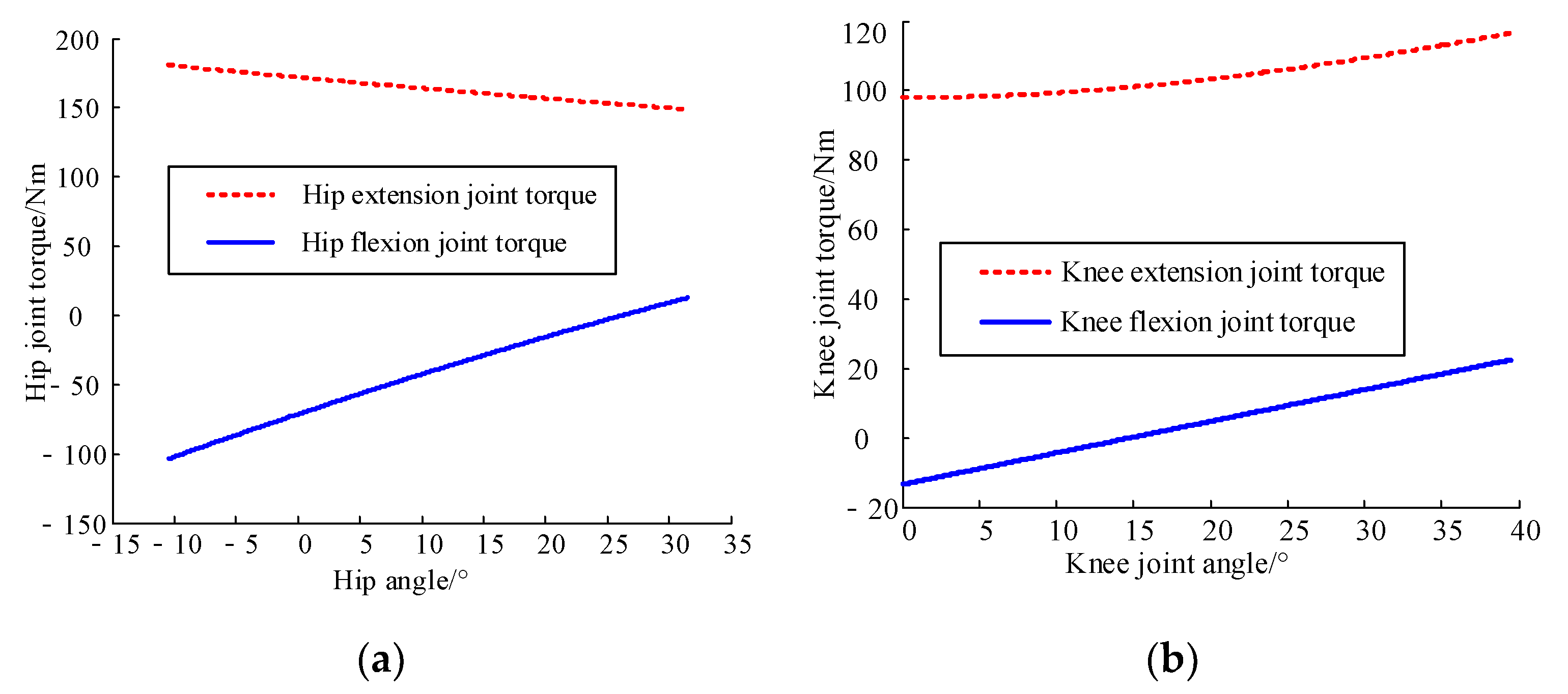
2.2.5. Analysis of the Static Moment Safety Protection of Human–Machine Linkage Model

When the patient is undergoing passive rehabilitation training, the traction of the rehabilitation robot will generate joint moments at each joint of the patient. If the rehabilitation robot exerts excessive force on the patient, it is easy to cause injury to the patient. This situation should be avoided in the control strategy, and the human–machine force during training should be controlled. The relationship between joint angle and joint torque can be obtained [31]:
{ T Hf = ( - 820.21 + 34.29 α H - 0.11426 α H 2 ) G e _ Hf T He = ( 3338.1 15.711 α H + 0.04626 α H 2 ) G e _ He T Kf = ( 94.437 + 6.3672 α K ) G e _ Kf T Ke = ( 1091.9 - 0.0996 α K + 0.17308 α K 2 - 0.00097 α K 3 ) G e _ Ke ,
where, T Hf , T He , T Kf and T K e represents hip flexion joint torque, hip extension joint torque, knee flexion joint torque and knee extension joint torque, respectively; αH and αK represent the angle between the human thigh and the torso, the angle between the human thigh and calf, respectively; and G e _ Hf , G e _ He , G e _ Kf , and G e _ Ke represent gender adjustment factors during the hip flexion movement, hip extension movement, knee flexion movement and knee extension movement, respectively.
Since the designed rehabilitation robot is mainly used by patients with limb movement disorders, the joint torque is smaller than that of a person with functioning limbs. In order to ensure the safety of patients during training, the adjustment factors, G e _ Hf = 0.0871 , G e _ He = 0.0516 , G e _ Kf = 0.0851 , and G e _ Ke = 0.0603 , are selected. By calculating the above Formula (11), the relationship between joint angle and joint torque can be obtained as shown in Figure 8. Based on the relationship between human joint angle and joint torque, and the relationship between the hip joint angle and the hip joint torque, the relationship between the knee joint angle and the knee joint torque are obtained, as shown in Figure 8. Therefore, if the human–machine interaction force does not exceed the above-mentioned limit in Figure 8 during the rehabilitation training process, the safety of the patients can be effectively guaranteed.

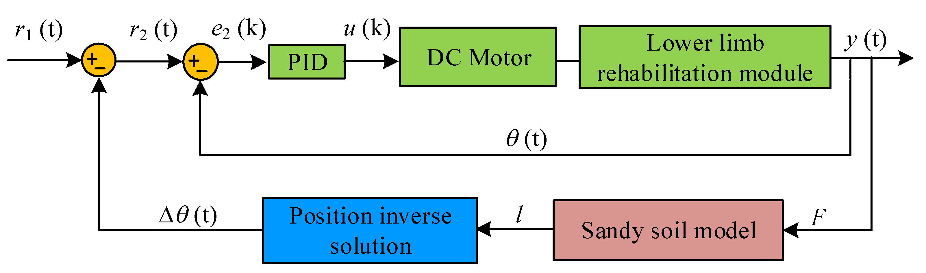
2.2.6. Active Training Control System of the Proposed Mechanism

When performing active rehabilitation training, it is also necessary to reconstruct the patient’s motor functions while judging the patient’s active training movement intention. The design process of the limb rehabilitation module simulating the sandy soil environment is introduced. Scholars from Newcastle University created a classic pressure model through long-term research and analysis of ground characteristics [32]:
{ p = ( k 1 + b k 2 ) ( l b ) n F = p A ,
where, p represents the pressure per unit area; b represents the radius of the circular plate; n represents the soil deformation index correction coefficient; k1 represents the cohesive deformation modulus correction coefficient; k2 represents the friction force modulus of deformation coefficient; l represents the amount of sandy soil subsidence; F represents the vertical load on the bearing plate; and A represents the bearing area.
For the absolute sandy soil model, k1 = 0. Therefore, the relationship between the amount of sandy soil subsidence l and the vertical load F can be calculated. The designed rehabilitation robot can adapt to the rehabilitation training of patients from lying to standing postures, and if patients meet the standing conditions, it is better for them to perform rehabilitation exercises in the standing posture. However, considering the design of the foot pedal of the rehabilitation robot, when the patient is undergoing active rehabilitation training, the movement direction of the patient’s foot is always parallel to the bed surface, and so the similar vertical sandy soil model is established. The specific force from the foot is shown in Figure 9.
The active training control block diagram based on the similar sandy soil model for active training is shown in Figure 10. The amount of human body sinking l is calculated, based on the vertical load F on the bearing plate through the similar sandy soil model, and then the geometric relationship of the lower limb rehabilitation module is used to solve the desired joint position Δθ(t) based on the calculated amount of sinking l. The new system input r2(t) can be obtained by adding it to the system input r1(t), and then adding it to the position deviation of the rehabilitation robot fed back by the inner control loop, resulting in the force caused by the pedal to simulate the sinking motion of the human foot. Additionally, by setting a different parameter k2, a different hardness of sandy soil environments can be obtained, so that different sandy soil environments can be simulated, and the feeling of stepping on the sandy soil can be reconstructed for the patient.

3. Results

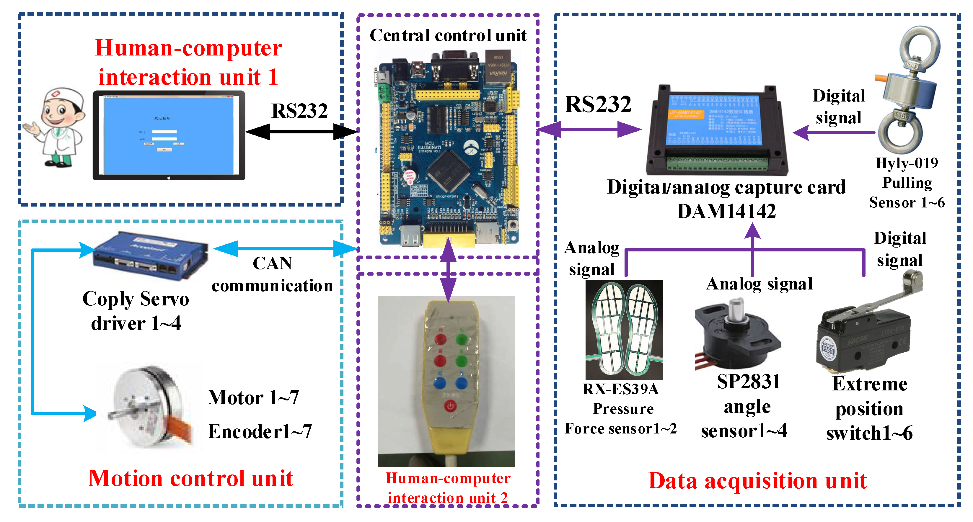
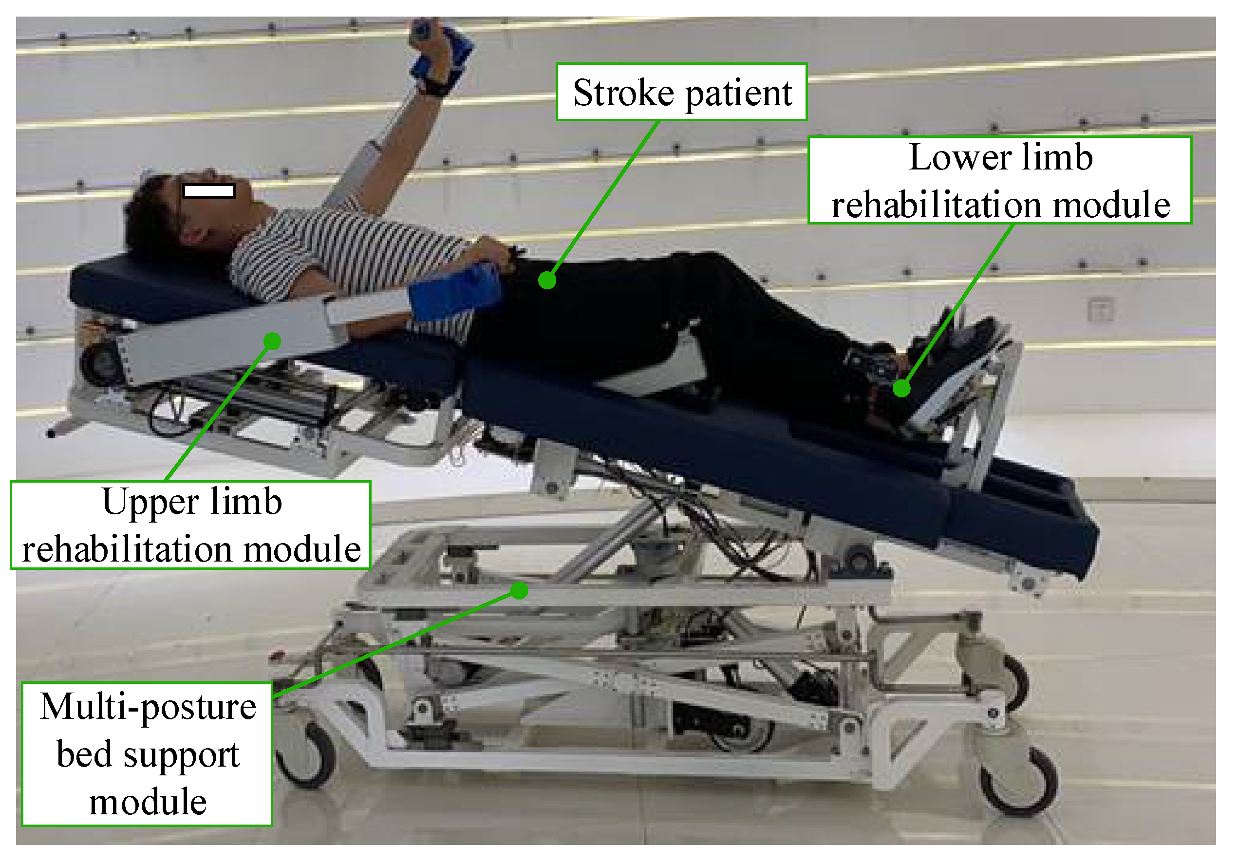
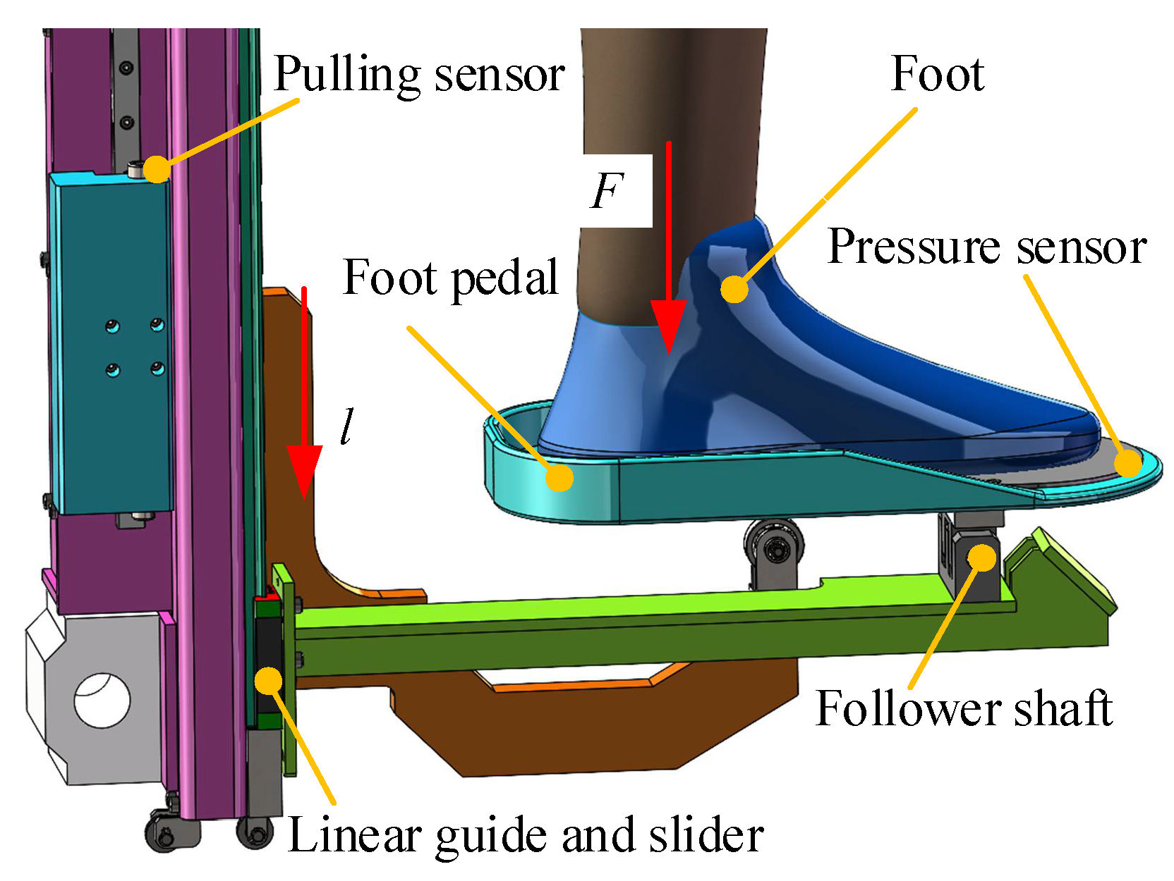
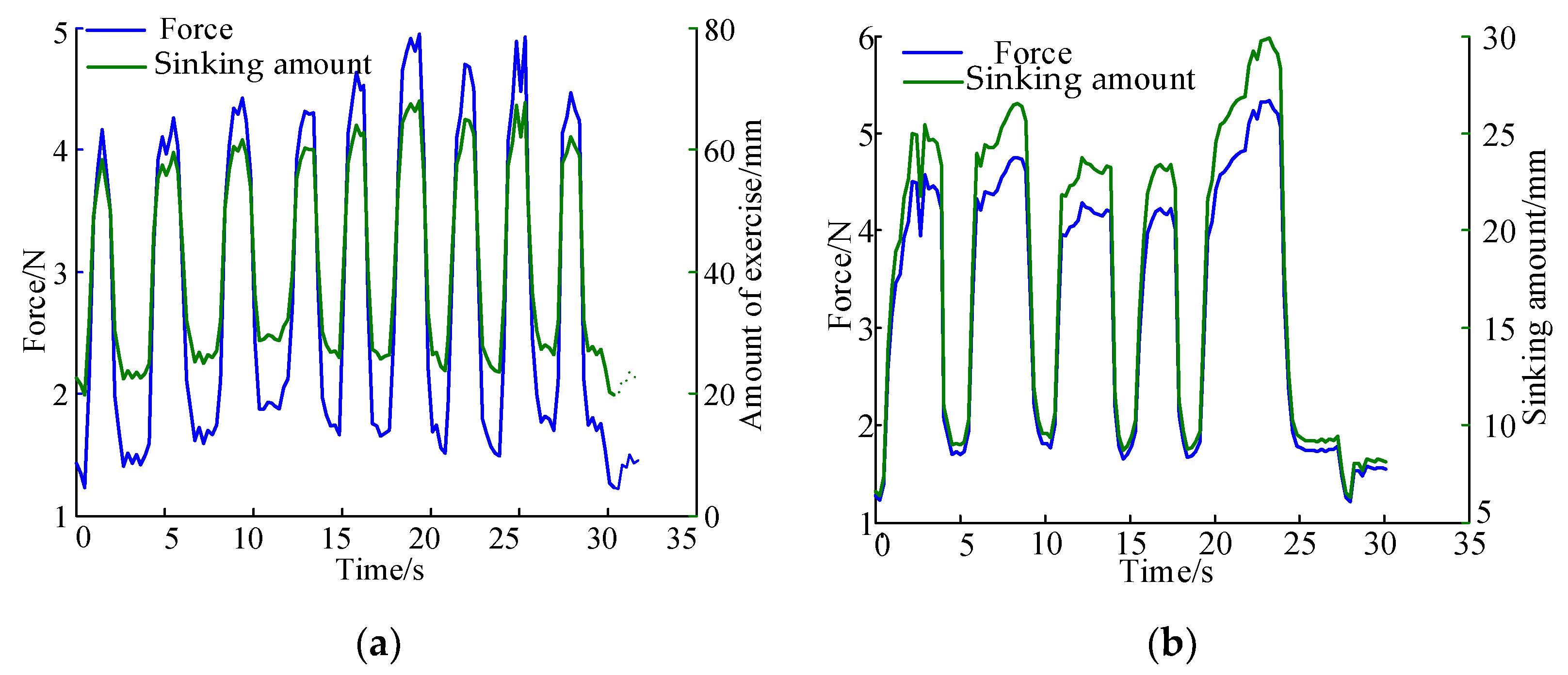
Rehabilitation Robot Experimental Platform Construction

In order to carry out the experimental verification of the mechanism design and control strategy of the proposed robot, the electrical system and the human–machine interaction interface of the robot are also designed. Figure 11 is a block diagram of the electrical system of the proposed rehabilitation robot, which mainly includes the central control unit, human–computer interaction unit, motion control unit and data acquisition unit.
The main function of the core of the central control unit is the STM32 single-chip microcomputer is to run the control program, receive and send operating instructions, and realize the coordinated control of the robot; the human–computer interaction unit includes a remote control and a touch-sensitive display. It is used for the input of control instructions for physician and patient rehabilitation parameter settings, etc. The motion control unit mainly includes the CAN communication module on a single-chip microcomputer, the Coply servo drive and the brushless DC motor. Its main function is to realize the joint motion of the robot through CAN communication. The data acquisition unit is composed of a data acquisition control module, a membrane pressure sensor, a pulling sensor (Hyly 019, Bengbu Hengyuan Sensor Technology Co., Ltd., Bengbu, China), an angle sensor (SP2831, Novotechnik, Germany) and a limit switch. Its main function is to collect the patient’s plantar pressure information, identify the patient’s movement intention, read the rotation angle of motor, and the limitation of the patient’s range of motion. A healthy volunteer was selected for the experiment. The related body parameters of the volunteer are shown in Table 2.
The experiment platform is developed as shown in Figure 12. To verify the trajectory and mechanism design, the starting point and end point of the training trajectory is set θ ( 0 ) = 0 and θ ( 2 ) = 2 π / 9 , and the position mode to control the motor is adopted. The robot drives the patient to train according to the theoretical trajectory, and then the error of the volunteer’s hip joint angular displacement can be obtained as shown in Figure 12b. The maximum difference between the theoretical curve and actual curve of the hip joint is 0.023 rad.
According to the pedal structure of the designed lower limb rehabilitation module, A = 29385.37 mm2 and b = 130 mm. The similar sandy soil model is established in a straight line perpendicular to the pedal, taking into account the normal gait of humans. In order to verify the designed active control strategy, the relevant parameters are as follows: the starting point (573.0, 0), the end point (653.0, 0), the inclination angle of the bed board (35°), the force is applied perpendicular to the pedal, and the parameters of the relevant sandy soil model are applied. The relevant parameters are selected as shown in Table 3.
The control of the lower limb rehabilitation module to move from the starting point to the set end position. After starting the training movement, the robot controls the hip joint movement module to rotate, and automatically records the data. Therefore, the relationship curve between the force exerted by the volunteer and the amount of motion can be obtained in the two sandy soil environments with a different hardness of sand, as shown in Figure 13. On the basis of the active training control block diagram, through the analysis of Figure 13, it can be seen that when the parameters are set through the soft sandy soil model, the amount of exercise is more clear, and the trend of the amount of exercise and the force change is also consistent, so that the volunteer can experience stepping on the ground with different hardnesses.

4. Discussion

For bedridden stroke patients, the uncoordinated and asymmetric motor function of the upper and lower limbs also inhibits the recovery process of human limb motor function. The proposed new synchronous rehabilitation robot for bedridden stroke patients’ upper and lower limbs has a very good research value, including preventing osteoporosis, increasing joint mobility, preventing joint contracture, improving cardiopulmonary function and promoting blood circulation and respiratory function. This paper focuses on the mechanism design of the lower limb rehabilitation module.
Compared with other multi-posture LLRTS, the performance of each mechanism is obtained as shown in Table 4. The proposed lower limb rehabilitation module cannot only realize the rehabilitation movement required by stroke patients, but also electrically adjusts the body shape of patients with a different weight and height. Moreover, due to the design of the weight compensation mechanism of ankle motion module in Figure 3, including the weight compensation part, the transmission cable and cable sheath and the foot plate, the movement range of the human heel is also larger than the other multi-posture LLRTS, such as Erigo [26]. The innovation of the weight compensation mechanism provides a certain reference value for the mechanism design of other rehabilitation robots. It also provides a basis for future personalized rehabilitation robot mechanism configuration.

5. Conclusions

This paper presents a synchronous rehabilitation robot for bedridden stroke patients’ upper and lower limbs and the mechanism of its lower limb rehabilitation module is introduced in detail. It not only can electrically adjust the body shape of patients with different weights and heights, but also increase the training range of the lower limb joints due to the innovative design of the weight compensation mechanism. The geometric relationship of the human–machine linkage mechanism is deduced and the dynamic analysis of the human–machine linkage mechanism is conducted, which provides a basis for the motor selection of the prototype. Based on the analysis of the static moment safety protection of the human–machine linkage model, the motor driving force required in the rehabilitation process is calculated to achieve the purpose of rationalizing the rehabilitation movement of the patient’s lower limb. To reconstruct the patient’s motor functions, an active training control strategy based on the sandy soil model is proposed. Finally, the experimental platform of the proposed robot is constructed and the preliminary physical experiment proves the feasibility of the lower limb rehabilitation component. In the future, diversified rehabilitation training strategies and the clinical research will be carried out.

Author Contributions

Conceptualization, Y.F.; methodology, X.W.; software, Y.L.; validation, J.Z., Y.Y. and J.N.; formal analysis, Y.F. and Y.L.; investigation, H.W.; resources, H.W.; writing—original draft preparation, X.W.; writing—review and editing, Y.F. and H.W.; visualization and supervision, H.W.; project administration, H.W.; funding acquisition, Y.F. and H.W. All authors have read and agreed to the published version of the manuscript.

Funding

This research was funded by the Joint Funds of the National Natural Science Foundation of China, grant number U1913216; Natural Science Foundation of Zhejiang Province, grant number LQ21E050008; Educational Commission of Zhejiang Province, grant number Y201941335; Natural Science Foundation of Ningbo City, grant number 2019A610110; The Major Scientific and Technological Projects in Ningbo City, grant number: 2020Z082; Research Fund Project of Ningbo University, grant number XYL19029; and the K. C. Wong Magna Fund of Ningbo University.

Institutional Review Board Statement

The study was conducted according to the guidelines of the Declaration of Helsinki, and approved by the Ethics Committee of Faculty of Mechanical Engineering & Mechanics, Ningbo University (protocol code [2021]LLSP(0810) and 2021.08.10).

Informed Consent Statement

The informed consent has been obtained from the patient(s) to publish this paper.

Data Availability Statement

The original data contributions presented in the study are included in the article, further inquiries can be directed to the corresponding authors.

Conflicts of Interest

The authors declare no conflict of interest.

References

  1. Tian, Y.; Wang, H.; Zhang, Y.; Su, B.; Wang, L.; Wang, X.; Sang, L.; Feng, Y.; Niu, J. Design and evaluation of a novel person transfer assist system. IEEE Access 2021, 9, 14306–14318. [Google Scholar] [CrossRef]
  2. Choi, W.H.; Takeda, Y. Geometric design and prototyping of a (2-RRU)-URR parallel mechanism for thumb rehabilitation therapy. Machines 2021, 9, 50. [Google Scholar] [CrossRef]
  3. Gassert, R.; Dietz, V. Rehabilitation robots for the treatment of sensorimotor deficits: A neurophysiological perspective. J. Neuroeng. Rehabil. 2018, 15, 46. [Google Scholar] [CrossRef] [PubMed] [Green Version]
  4. Mayr, A.; Quirbach, E.; Picelli, A.; Kofler, M.; Smania, N.; Saltuari, L. Early robot-assisted gait retraining in non-ambulatory patients with stroke: A single blind randomized controlled trial. Eur. J. Phys. Rehabil. Med. 2018, 54, 819–826. [Google Scholar] [CrossRef]
  5. Wang, L.D.; Wang, J.H.; Peng, B.; Xu, Y.M. Brief report on stroke prevention and treatment in China. Chin. J. Cerebrovasc. Dis. 2020, 17, 272–281. [Google Scholar]
  6. Doost, M.Y.; Herman, B.; Denis, A.; Sapin, J.; Galinski, D.; Riga, A.; Laloux, P.; Bihin, B.; Vandermeeren, Y. Bimanual motor skill learning and robotic assistance for chronic hemiparetic stroke: A randomized controlled trial. Neural Regen. Res. 2021, 16, 1566–1573. [Google Scholar]
  7. Birouaș, F.I.; Țarcă, R.C.; Dzitac, S.; Dzitac, I. Preliminary results in testing of a novel asymmetric underactuated robotic hand exoskeleton for motor impairment rehabilitation. Symmetry 2020, 12, 1470. [Google Scholar] [CrossRef]
  8. Sconza, C.; Negrini, F.; Di Matteo, B.; Borboni, A.; Boccia, G.; Petrikonis, I.; Stankevičius, E.; Casale, R. Robot-Assisted Gait Training in Patients with Multiple Sclerosis: A Randomized Controlled Crossover Trial. Medicina 2021, 57, 713. [Google Scholar] [CrossRef]
  9. Coleman, E.R.; Moudgal, R.; Lang, K.; Hyacinth, H.I.; Awosika, O.O.; Kissela, B.M.; Feng, W. Early rehabilitation after stroke: A narrative review. Curr. Atheroscler. Rep. 2017, 30, 59. [Google Scholar] [CrossRef] [Green Version]
  10. D’Onofrio, G.; Fiorini, L.; Hoshino, H.; Matsumori, A.; Okabe, Y.; Tsukamoto, M.; Limosani, R.; Vitanza, A.; Greco, F.; Greco, A.; et al. Assistive robots for socialization in elderly people: Results pertaining to the needs of the users. Aging Clin. Exp. Res. 2019, 31, 1313–1329. [Google Scholar] [CrossRef]
  11. Russo, M.; Ceccarelli, M. Analysis of a wearable robotic system for ankle rehabilitation. Machines 2020, 8, 48. [Google Scholar] [CrossRef]
  12. Mezzarane, R.A.; Klimstra, M.; Lewis, A.; Hundza, S.R.; Zehr, E.P. Interlimb coupling from the arms to legs is differentially specified for populations of motor units comprising the compound h-reflex during “reduced” human locomotion. Exp. Brain Res. 2011, 208, 157–168. [Google Scholar] [CrossRef] [PubMed]
  13. Susanto, S.; Simorangkir, I.T.; Analia, R.; Pamungkas, D.S.; Soebhakti, H.; Sani, A.; Caesarendra, W. Real-time identification of knee joint walking gait as preliminary signal for developing lower limb exoskeleton. Electronics 2021, 10, 2117. [Google Scholar] [CrossRef]
  14. Nasiri, R.; Shushtari, M.; Arami, A. An Adaptive assistance controller to optimize the exoskeleton contribution in rehabilitation. Robotics 2021, 10, 95. [Google Scholar] [CrossRef]
  15. Penzlin, B.; Bergmann, L.; Li, Y.; Ji, L.; Leonhardt, S.; Ngo, C. Design and first operation of an active lower limb exoskeleton with parallel elastic actuation. Actuators 2021, 10, 75. [Google Scholar] [CrossRef]
  16. Van Kammen, K.; Reinders-Messelink, H.A.; Elsinghorst, A.L.; Wesselink, C.F.; Meeuwisse-de Vries, B.; van der Woude, L.H.; Boonstra, A.M.; den Otter, R. Amplitude and stride-to-stride variability of muscle activity during Lokomat guided walking and treadmill walking in children with cerebral palsy. Eur. J. Paediatr. Neurol. 2021, 29, 108–117. [Google Scholar] [CrossRef] [PubMed]
  17. Tan, K.; Koyama, S.; Sakurai, H.; Teranishi, T.; Kanada, Y.; Tanabe, S. Wearable robotic exoskeleton for gait reconstruction in patients with spinal cord injury: A literature review. J. Orthop. Transl. 2021, 28, 55–64. [Google Scholar]
  18. Feng, Y.; Wang, H.; Lu, T.; Vladareanuv, V.; Li, Q.; Zhao, C. Teaching training method of a lower limb rehabilitation robot. Int. J. Adv. Robot. Syst. 2016, 13, 57. [Google Scholar] [CrossRef] [Green Version]
  19. Feng, Y.; Wang, H.; Vladareanu, L.; Chen, Z.; Jin, D. New motion intention acquisition method of lower limb rehabilitation robot based on static torque sensors. Sensors 2019, 19, 3439. [Google Scholar] [CrossRef] [Green Version]
  20. Kumar, S.; Yadav, R.A.; Aafreen; Yadav, S. Effect of robotic tilt table on rehabilitation outcome in right side versus left side hemiplegia. Int. J. Yogic Hum. Mov. Sports Sci. 2018, 3, 237–241. [Google Scholar]
  21. Fang, J.; Xie, Q.; Yang, G.Y.; Xie, L. Development and feasibility assessment of a rotational orthosis for walking with arm swing. Front. Neurosci. 2017, 11, 32. [Google Scholar] [CrossRef] [Green Version]
  22. Lee, H.Y.; Park, J.H.; Kim, T.W. Comparisons between Locomat and Walkbot robotic gait training regarding balance and lower extremity function among non-ambulatory chronic acquired brain injury survivors. Medicine 2021, 100, e25125. [Google Scholar] [CrossRef] [PubMed]
  23. Aurich-Schuler, T.; Gut, A.; Labruyere, R. The FreeD module for the Lokomat facilitates a physiological movement pattern in healthy people—A proof of concept study. J. Neuroeng. Rehabil. 2019, 16, 26. [Google Scholar] [CrossRef] [PubMed]
  24. Lee, J.; Li, L.; Shin, S.Y.; Deshpande, A.D.; Sulzer, J. Kinematic comparison of single degree-of-freedom robotic gait trainers. Mech. Mach. Theory 2021, 159, 104258. [Google Scholar] [CrossRef]
  25. Wang, H.; Feng, Y.; Yu, H.; Wang, Z.; Vladareanuv, V.; Du, Y. Mechanical design and trajectory planning of a lower limb rehabilitation robot with a variable workspace. Int. J. Adv. Robot. Syst. 2018, 15. [Google Scholar] [CrossRef] [Green Version]
  26. Wang, X.; Wang, H.; Hu, X.; Tian, Y.; Lin, M.; Yan, H.; Niu, J.; Sun, L. Adaptive direct teaching control with variable load of the lower limb rehabilitation robot (LLR-II). Machines 2021, 9, 142. [Google Scholar] [CrossRef]
  27. Daunoraviciene, K.; Adomaviciene, A.; Svirskis, D.; Griškevičius, J.; Juocevicius, A. Necessity of early-stage verticalization in patients with brain and spinal cord injuries: Preliminary study. Technol. Health Care 2018, 26, 613–623. [Google Scholar] [CrossRef] [Green Version]
  28. Tian, C. Design of Multi-Step Synergy Rehabilitation Model Based on Flexbot Rehabilitation Robot Platform. Master’s Thesis, Shenzhen University, Shenzhen, China, 19 May 2019. [Google Scholar]
  29. Wang, H.; Wu, J.; Wang, Y.; Ren, L.; Zhang, D.; Lu, H. Research on the lower limb gait rehabilitation. In Proceedings of the 2014 IEEE International Conference on Mechatronics and Automation, Tianjin, China, 3–6 August 2014; IEEE: New York, NY, USA, 2014. [Google Scholar]
  30. Weng, C.S.; Bi, S.; Xie, Y.J.; YU, Z.Z.; Qin, Y.; Wu, Y.M.; Lu, Y.H. Relationship between walking speed and step length and walking rate in hemiparetic stroke patients. Chin. J. Clin. Rehabil. 2003, 7, 1108–1109. [Google Scholar]
  31. Gu, Y.L. A Journey from Robot to Digital Human: Mathematical Principles and Applications with MATLAB Programming, 1st ed.; Springer: Heidelberg, Germany, 2013; pp. 435–445. [Google Scholar]
  32. Wong, J.Y.; Reece, A.R. Prediction of rigid wheel performance based on the analysis of soil-wheel stresses: Part II. Performance of driven rigid wheels. J. Terramech. 1967, 4, 7–25. [Google Scholar] [CrossRef]
Figure 1. Overall structure of upper and lower limb synchronous rehabilitation robot for bedridden stroke patients.
Machines 09 00224 g001
Figure 2. Spatial motion diagram of rigid linkage mechanism of human lower limb.
Machines 09 00224 g002
Figure 3. Mechanism design of lower limb rehabilitation module.
Machines 09 00224 g003
Figure 4. Human–machine model of lower limb rehabilitation module.
Machines 09 00224 g004
Figure 5. The simulation of the hip joint. (a) Angular displacement curve (b) Angular velocity curve; (c) Angular acceleration curve.
Machines 09 00224 g005
Figure 6. The simulation of the movement of the ankle joint axis. (a) Displacement curve; (b) Angular velocity curve; (c) Angular acceleration curve.
Machines 09 00224 g006
Figure 7. Simulation curve of motor driving force. (a) The motor driving torque changes with tf and t; (b) The changes of time tf and t; (c) The motor driving torque changes with t; (d) The motor driving torque changes with tf.
Machines 09 00224 g007
Figure 8. The relationship between joint angle and joint torque of lower limb. (a) The relationship between the hip joint angle and the hip joint torque; (b) The relationship between the knee joint angle and the knee joint torque.
Machines 09 00224 g008
Figure 9. Design of similar sandy soil model for active training.
Machines 09 00224 g009
Figure 10. Active training control block diagram based on sandy soil model.
Machines 09 00224 g010
Figure 11. Block diagram of the electrical system of the bed rehabilitation robot.
Machines 09 00224 g011
Figure 12. The prototype of the proposed rehabilitation robot. (a) Experiment platform with the volunteer; (b) Hip joint angular displacement error curve.
Machines 09 00224 g012
Figure 13. The planned trajectory of the hip joint through the experiment platform. (a) Softer sandy soil model; (b) Harder sandy soil model.
Machines 09 00224 g013
Table 1. Human gait parameters.
NameStride (cm)Step Width (cm)Step Frequency (min−1)Step Height (cm)Hip Joint Range (°)
Parameters45–905–1090–1255–10−20–120
Table 2. The size range of each joint of volunteers.
VolunteerGenderAge HeightThigh LengthCalf Length
XuMan261720 (mm)492 (mm)398 (mm)
Table 3. Related sandy soil model parameters.
Sandy Soil Environmentk1k2n
Harder06.270.95
Softer00.901.15
Table 4. Performance comparison of the multi-posture LLRTS.
Product NameTraining JointsRange of
Motion
Human Height
Adjustment
Human Fat and Thin Shape AdjustmentManufacturing
Cost
ROWAS [20]Hip, knee and ankleLarge YesYesHigh
Flexbot [27]Hip, knee and ankleLargeYesYes High
The proposed robotHip, knee and ankleLargeYesYes Low
Erigo [26]Hip, knee and ankleSmallYesNoLow
Publisher’s Note: MDPI stays neutral with regard to jurisdictional claims in published maps and institutional affiliations.

