Abstract
Metal Material Extrusion (MEX/M) provides a rapid, low-cost additive manufacturing option for individual and batch productions; however, cast materials are not typically available in the material pool. White cast iron is subject to long casting lead times and high foundry costsThis research details a comparative sintering process study for MEX/M printed white cast iron, a novel addition to the metal additive manufacturing field. A mechanical properties and microscopic evaluation on MEX/M white cast iron samples was completed to compare the influence of three sintering parameters: peak sintering temperature, dwell time, and cooling process. It was observed that increasing the peak sintering temperature increased the sintered density by 23.2% and the volumetric shrinkage by 14.25%. A longer dwell time increased the sintered density by 30.1% and the volumetric shrinkage by 9.42% but decreased the microhardness of the sample. A change in the cooling process of the sample had no effect on the mechanical properties or the microstructure of the sample. The samples achieved a 79.9% increased average density after sintering to 5.75 g/cc, with 57.82% volumetric shrinkage and a 23.3% mass loss. Overall, the samples were 85.8% less dense than casted white cast iron but showed features of a white cast iron microstructure.
1. Introduction
Metal additive manufacturing (AM) enables the quick and efficient production of individual and batch metal parts that cannot be produced using traditional subtractive manufacturing methods. While most metal AM technologies suffer from high setup and operating costs, Material Extrusion (MEX) provides a low-cost metal AM option [1]. Material Extrusion infuses additive-grade metallic powder within the thermoplastic to produce a metal part in the shape of the printed thermoplastic [2]. Material Extrusion follows three simple steps:
- Print: Material Extrusion deposits layer upon layer of heated thermoplastic filament to produce a printed shape of the intended part [2].
- Debind: Thermal debinding slowly vaporizes the thermoplastic binder, resulting in just the metallic powder being left behind [2].
- Sinter: The remaining metallic powder is heated to a liquid-like state, allowing it to connect and fuse as it cools [2].
Sintering parameters such as the peak sinter temperature, dwell time, and the cooling process can greatly affect the outcome of an MEX/M printed sample. The peak sinter temperature is the maximum temperature the samples reach during the sintering cycle, when the sample is in the most liquid-like state. The dwell time is the length of time the sample is held at the peak sinter temperature. Additionally, the cooling process is the peak sintering temperature until the completion of the sintering cycle. All three of these parameters can influence the sample’s shape, the microstructure formed, and the mechanical properties.
Within the current research, there are only a few studies investigating the effects of sintering parameters on the mechanical properties and microstructure of an MEX/M printed part. Additionally, there are no studies working on additive manufacturing of cast iron, resulting in comparisons being drawn from high-melting-point iron alloys. Mousapour et al. [3] investigated the effect of different peak sintering temperatures and dwell times on MEX/M printed 316L stainless steel (SS). Samples were sintered with peak sintering temperatures of 1310, 1320, 1330, 1360 and 1400 °C. Dwell times were compared at 1, 6, and 12 h, at a sinter temperature of 1360 °C. The peak sintering temperature comparison revealed that the highest relative density of approximately 90% was achieved at a peak sintering temperature of 1360 °C. A longer dwell time resulted in a higher relative density, with samples sintering at 1360 °C for 12 h achieving the highest relative density of 92% [3]. Ortega Varela de Seijas et al. [4] tested flash sintering, with dwell times from 10 s to 6 min at 1350 °C on MEX/M printed 316L SS samples. Longer sintering dwell times showed denser samples: a 10 s sintering time achieved a density of 66.4% while 240 s achieved a density of 99.9%. The standard sintering process showed a higher sintered density compared to sintering completed in a vacuum environment [4].
Wagner et al. [5] investigated the effect of the peak sintering temperature on MEX/M printed 17-4PH SS. It was shown that peak sintering temperatures ranging from 1200 °C to 1300 °C resulted in no change in the sample’s final density. However, peak sintering temperatures of 1350 °C and 1360 °C produced samples that were 9% denser compared to those sintered at 1300 °C and below [5]. Abe et al. [6] compared the microstructure between as-sintered and aging heat-treated 17-4PH SS samples. Samples sintered for 2 h at 1280 °C showed little change in the microstructure; thus, the aging heat treatment was deemed ineffective. Charpentier et al. [7] investigated MEX/M printed high-carbon tool steel at different dwell times, with a peak sintering temperature of 1280 °C. It was found that longer dwell times resulted in less measured rugosity, with only a 0.14% reduction in porosity [7].
Following sintering, Liu et al. [8], Ghadimi et al. [9], and Kedziora et al. [10] noted that printing layer lines remained visible in the sintered sample’s microstructure. Similarly, Kurose et al. [11] examined the fracture surfaces of MEX/M printed 316L SS tensile tests. The authors noted that the samples with layer directions going parallel to the applied force resulted in lower tensile strengths as the layer lines acted as defects within the printed part [11].
With the current limitations in the MEX/M material pool, novel materials such as cast iron will open new applications across the automotive, mining, agricultural, and renewable energy industries [12]. Additively manufacturing high-quality “cast” parts in-house allows industry to skip the casting costs and lead times [13,14]. Currently, there has been significant research into sintering parameters on high-melt iron alloys such as stainless steel and tool steel, but there has been no research into the sintering parameters for the Material Extrusion of cast iron. Unlike steel, sintering the high-carbon content in cast iron creates a unique and complex cast microstructure, which dictates its mechanical properties. The presented research of additive manufacturing of cast iron using MEX/M provides a baseline for further research for both cast iron and other typically cast materials. Additionally, this allows the MEX/M material pool to grow and proves that a complex cast microstructure can be achieved using additive manufacturing technology. This study documents an experimental exploration of key sintering process parameters: peak sintering temperature, dwell time, and the cooling process for MEX/M printed white cast iron samples. Printed samples are sintered with varying process parameters, followed by a comparison of the mechanical properties and microstructures. This research provides introductory experimental data regarding the effects of the peak sintering temperature, dwell time, and the cooling process on MEX/M printed white cast iron samples.
2. Experimental Setup
White cast iron filament was printed using a Creality Ender 5 Plus 3D printer (Creality, Shenzhen, China) with a MicroSwiss direct drive system and a 1.0 mm hardened steel nozzle, as shown in Figure 1. The material is a 1.75 mm diameter high-carbon (cast iron) Filamet™ produced by The Virtual Foundry (Stoughton, WI, USA), which had 79.1 percent metal powder by weight.
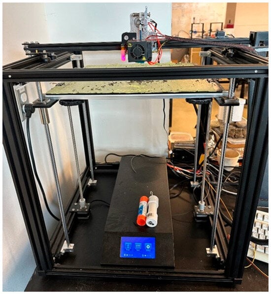
Figure 1.
Creality Ender 5 Plus used in this study to print using cast iron Filamet™.
As shown in Figure 2a, debinding and sintering were completed in a Paragon kiln with a maximum sintering temperature of 1370 °C. Samples were placed in a 500 mL alumina crucible with steel sintering ballast, which holds the sample’s shape. Sintering carbon was laid on top of the sintering carbon to prevent oxidation of both the ballast and samples. The VHX series digital microscope (Keyence Canada Inc., Mississauga, ON, Canada) shown in Figure 2b was utilized to examine the porosity and microstructure of the sintered cast iron samples. The average microhardness was measured in 3 different locations to the ASTM E384 standard [15] using a dwell time of 10 s and a force load of 300 gf.
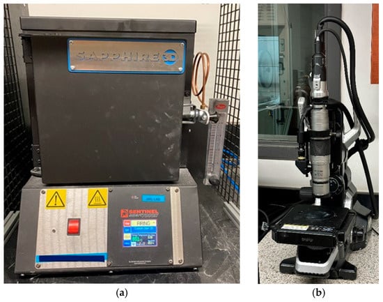
Figure 2.
(a) Paragon Programmable Kiln; (b) VHX series digital microscope.
3. Methodology
The experimental workflow will follow the three-step process outlined in the introduction: (1) printing, (2) debinding, (3) sintering. In practice, samples printed from the cast iron filament are transferred to the kiln for debinding and sintering. Thermal debinding is completed at the beginning of the sinter cycle, and samples are then subjected to the complete sintering cycle, resulting in a fused cast iron sample.
For printing, cylindrical samples were printed in accordance with ASTM International E9 standard [16], with an average measured diameter of 12.7 mm and an average measured height of 25.4 mm, as shown in Figure 3. The sample height and diameter are measured using digital calipers and mass measured using a digital scale. Density was calculated using the Archimedean method, comparing the measured volume to the measured mass. Based on previous research, samples were printed using specific parameters, 185% flow rate, 100% infill density, 0.20 mm layer height, 215 °C nozzle temperature, and a 45 °C bed temperature [17].
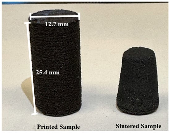
Figure 3.
Metal MEX printed (left) and sintered (right) cast iron samples.
To begin the sintering step, more information about the composition of the sample during sintering was needed as this determines the basis for the final part’s microstructure and mechanical properties. Samples were subject to only the debinding phase to remove the thermoplastic, resulting in a pure powder sample. The powder was sent for chemical composition testing, and the results are shown below in Table 1.

Table 1.
Chemical composition of the cast iron filament.
Based on the chemical composition of the cast iron filament, the target cast type was white cast iron [9,10].
In preparation for sintering, samples were placed on a bed of steel sintering ballast in a 500 mL alumina crucible and covered with additional steel sintering ballast. The steel sintering ballast was tamped down to support and maintain the print’s shape. To prevent oxidation, the sintering carbon was added to the top of the steel sintering ballast. To begin sintering, the crucible was then placed in the center of the kiln for firing. The sintering cycle started by increasing the temperature at a rate of 115 °C/h until it reached 250 °C. This temperature was held for two hours for the thermoplastic binder to break down and vaporize. Next, the temperature was raised at the same rate to 425 °C and held for two hours to allow for complete vaporization of the thermoplastic binder. After this stage, the kiln temperature was raised to a sub-sinter temperature of 600 °C and held for two hours, to allow the crucible reach to an even thermal distribution. Following this hold period, the kiln temperature increased to the peak sinter temperature at the fastest rate the kiln could achieve. Upon reaching the peak sinter temperature, the temperature was held for the set dwell time. At the end of the dwell time, the kiln was cooled by 115 °C/h until it reached 600 °C; the kiln was then shut off to cool to room temperature. This sintering cycle, displayed in Figure 4, was the baseline of this research, with the peak sintering temperature, dwell time and cooling process compared for each sample.
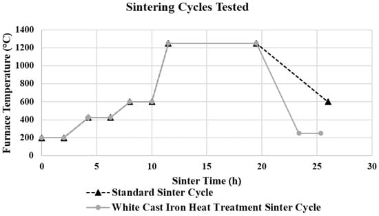
Figure 4.
Cast iron sintering cycles compared in this study.
The initial comparative tests began with peak sintering temperatures of 80–90% of the melting temperature, as recommended by The Virtual Foundry [18]. To encompass the sintering range from 1230 to 1350 °C, the sintering trials started just below the 80% mark at 1225 °C. The temperature increased in 25 °C intervals until the samples were deformed. The peak sintering temperature was deemed acceptable if the sample was fully sintered without significant uncontrollable deformation.
To compare dwell times, The Virtual Foundry recommended starting with a dwell time of four hours. As previously mentioned in the literature review, Mousapour et al. [3] found the best relative density achieved at a sintering dwell time of 12 h. Once an acceptable peak sintering temperature was established, sintering dwell time trials had a constant peak sinter temperature, with comparisons at 4, 8 and 12 h. Initial trials were started using a constant 8 h peak sinter temperature dwell time.
Once a peak sintering temperature and a dwell time yielding acceptable results were established, a comparison could be made between the cooling rates. Typically, cast iron goes through many heat treatment processes, with stress relief commonly the only in-process heat treatment process applied to white cast iron [19]. Stress relief helps ease residual stresses in complex and changing geometries during the casting process. Although this study did not investigate the residual stresses or any samples with complex geometries, a comparison was still completed to study the effects of stress relief heat treatment on the microstructures and mechanical properties [20]. Stress relief was applied as a comparison of the effect of an increased cooling rate compared to the standard recommended by The Virtual Foundry. Stress relief for cast iron consists of cooling the sample from the peak sintering temperature at a rate of 260 °C/h until it reaches 250 °C, which is then held for two hours [19]. This would be a cooling rate approximately 2.3-times quicker than the standard MEX/M cooling process. The complete design of the experiments can be seen in Table 2.
Table 2.
Sintering design of experiments.
Following completion of the sintering, samples were removed from the crucible and measured for mechanical properties. The sintered samples’ mass, top diameter, middle diameter, bottom diameter, and height were measured and recorded. Samples were subsequently cut in half and set into polymer for polishing to a 1 μm surface finish. Polished samples were examined for porosity and microhardness before a nitric and hydrochloric acid water mixture (1Ni:2HCL:2 Water) was applied to etch samples for microstructure examination. The etching removes the ferrite, presenting the carbon formations.
4. Results
White cast iron samples were printed with an average diameter, height, density, and mass of 12.95 mm, 25.88 mm, 3.14 g/cc, and 10.71 g. The sintered white cast iron samples had an average dimensional shrinkage of 17.81% in the x-y direction and 37.38% in the z-direction. The increased shrinkage in the z-direction is due to the gravitational effects acting on the sample during sintering. The sintered samples averaged a mass loss of 25.6%, with a density increase of 79.6% compared to the unsintered printed samples. Sintered mass values were 35.7% to 16.8% lower (6.96 g to 9.00 g) than the average printed mass of 10.82 g. This is to be expected as a successful sinter involves the removal of the binder and a liquid-like melt, resulting in increased sample shrinkage. Expanded printed and sintered sample data can be viewed in Table 3.
Table 3.
Mechanical properties for printed and sintered samples.
There was no change in sintered mass as the amount of metallic filament in the sample did not change with the sintering cycle. Increasing the peak sinter temperature from 1225 °C to 1275 °C resulted in a 23.2% sintered density increase from 4.81 g/cc to 6.26 g/cc, accompanied by a volumetric shrinkage increase from 52.18% to 66.43%. The increased sintered density and volumetric shrinkage at higher peak sintering temperatures are due to a higher liquidous volume that further fills the porous sample. The heat treatment cycle did not affect the mechanical properties of the sintered sample.
The sintered density and volumetric shrinkage both increased as the dwell time at 1250 °C increased. The sintered density increased from 4.83 g/cc to 6.09 g/cc and 6.21 g/cc as the dwell time was increased from 4 to 8 to 12 h, respectively. The volumetric shrinkage increased from 52.27% to 61.69% as the dwell time increased. The rise in sintered density and volumetric shrinkage is due to the longer dwell time, allowing the semi-liquidous sample to fill pores left behind after debinding.
The samples’ microhardness decreased from 388 HV to 245 HV and to 198 HV as the dwell time at 1250 °C was increased from 4 to 8 to 12 h. No significant change in the microhardness was evident as the peak sintering temperature varied or with the heat treatment cooling process. The microhardness decreased with longer sinter dwell times, as expected, due to the hard carbide decomposing over time and softer microstructures forming.
The various dwell times at the 1250 °C peak sinter temperature exhibited no significant change in the measured porosity percentage of the samples. This could be a result of a much slower sample shrinkage, which created uniform porosity throughout the sample. Increasing the peak sinter temperature from 1225 °C to 1275 °C resulted in a 37.9% lower measured porosity percentage.
Across all sintering trials, the lowest volumetric shrinkage (52.18%) and lowest sintering density (4.81 g/cc) occurred at a peak sinter temperature of 1225 °C with a dwell time of 8 h using the standard cooldown approach. The highest volumetric shrinkage (66.43%) and sintered density (6.26 g/cc) occurred at the peak sinter temperature of 1275 °C with an 8 h dwell time using the standard cooldown approach. Additionally, the cast iron sintered samples primarily showed a white cast iron microstructure across all sintering trials. As shown in Figure 5a (the sample sintered at 1250 °C for 12 h using a standard cooldown process), the cementite plates were surrounded by coarse and fine pearlite grains, a microstructure typically seen in white cast iron (Figure 5b).
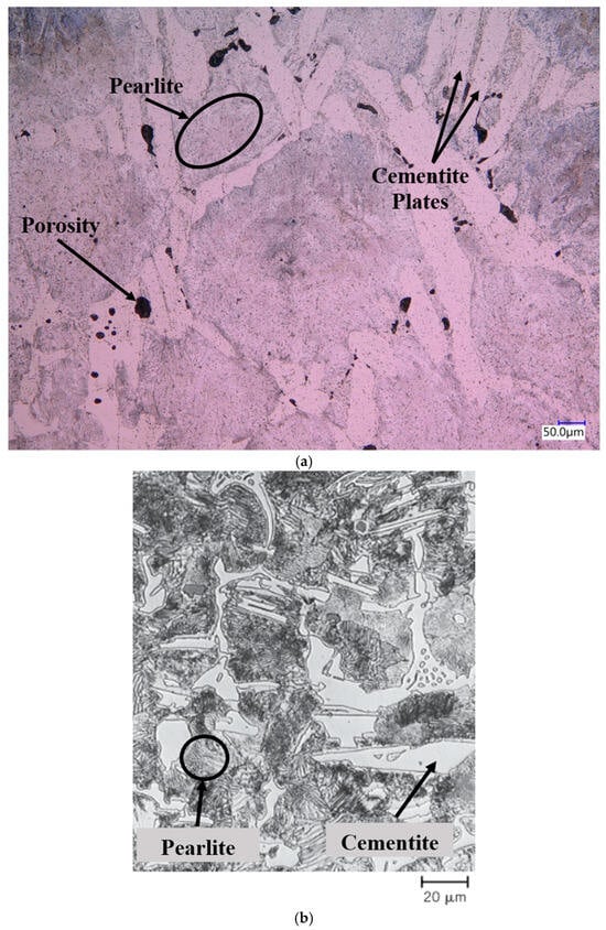
Figure 5.
(a) Microstructure for the cast iron sintered at 1250 °C for 12 h using the standard cooldown process (the image is at 300× zoom); (b) white cast iron microstructure [21].
A change in the dwell time showed increased amounts of austenite in samples sintered for 12 h. Samples compared with different peak sintering temperatures showed more variability within the presented microstructure. Samples sintered at 1225 °C, seen in Figure 6a, showed significant ledeburite within the sample. Samples sintered at 1250 °C for 8 h, seen in Figure 6b, showed flakey graphite carbon deposits commonly seen in gray cast iron [21]. These small flaky graphite carbon deposits are found throughout the sample but are not at the same scale typically seen in gray cast iron.
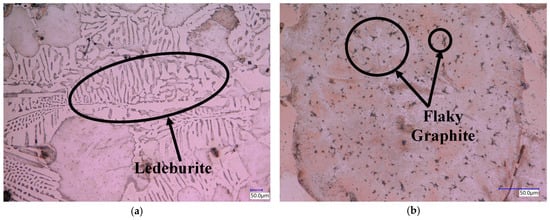
Figure 6.
(a) Microstructure for cast iron sintered at 1225 °C for 8 h using a standard cooldown process (the image is shown at 300× zoom); (b) flaky graphite microstructure for cast iron sintered at 1275 °C for 8 h using a standard cooldown process (the image is shown at 1000× zoom).
The samples subjected to the increased cooling rate during the stress relief heat treatment exhibited a reduction in coarse pearlite within the grains, along with small carbon specks scattered throughout the microstructure, as shown in Figure 7. Table 4 presents a full porosity and microstructure breakdown for all the sintered cast iron samples.
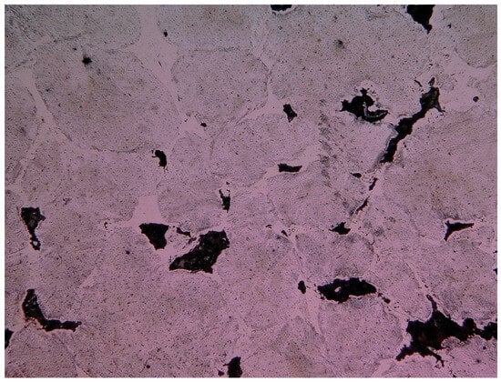
Figure 7.
Microstructure for cast iron sintered at 1250 °C for 8 h using the stress relief heat treatment cooldown process; the image is shown at 300× zoom.
Table 4.
Microstructure results for sintering trials.
5. Conclusions
This research investigated the effects of different key sintering parameters on MEX/M printed white cast iron samples. The resulting porosity, density, shrinkage, and microscopic imaging were used to evaluate the effects of peak sinter temperature, dwell time, and the cooling process for MEX/M printed white cast iron. Conclusions from this research are summarized below:
- A typically cast, white cast iron microstructure featuring coarse and fine pearlite can be created using MEX/M printing techniques.
- Similar to other studies, the peak sinter temperature influences the sintered density, volumetric shrinkage, and sintered porosity of the sample [3,4,5]. Elevating the peak sinter temperature from 1225 °C to 1275 °C increased the sintered density by 23.2% and the shrinkage by 14.25%.
- The dwell time influences the sintered density, volumetric shrinkage, and microhardness of the sample. This was to be expected, as similar results were reported in the literature review [4]. Longer dwell times increased the sintered density by 30.1% and volumetric shrinkage by 9.42%.
- The stress relief heat treatment used to compare the MEX/M cooling rate for printed white cast iron samples had no effect on the mechanical properties or microstructure of the sample. Similarly, Abe et al. [6] reported that heat treatment was ineffective.
- Samples only achieved 85.8% of the density of white cast iron. This is due to the large porosity within the sample [22].
- Significant uncontrollable shrinkage combined with large internal porosity makes Material Extrusion of white cast iron infeasible for commercial use.
- Further sintering optimization to control the shrinkage and mechanical properties of the cast iron sample can enable MEX/M printed cast iron parts for use across various industries.
Author Contributions
M.D.: Conceptualization, investigation, methodology, data curation, formal analysis, validation, and writing—original draft. G.M.: Data curation and formal analysis. A.E.: Project administration, writing—review and editing. I.D.: Funding acquisition, project administration, writing—review and editing, and supervision. All authors have read and agreed to the published version of the manuscript.
Funding
The authors declare that this study received funding from the Natural Sciences and Engineering Research Council of Canada (NSERC) and CGL Manufacturing Inc. (An Arrow Machine and Fabrication Group Company). NSERC grant number: 401670.
Data Availability Statement
Data are contained within the article.
Acknowledgments
The authors would like to acknowledge the support of members from the Advanced Manufacturing Laboratory, School of Engineering, University of Guelph. The authors acknowledge the financial support from the Natural Sciences and Engineering Research Council of Canada (NSERC) and CGL Manufacturing Inc. (An Arrow Machine and Fabrication Group Company).
Conflicts of Interest
The authors declare that this study received funding from CGL Manufacturing Inc. (An Arrow Machine and Fabrication Group Company). The funder was not involved in the study design, collection, analysis, interpretation of data, the writing of this article or the decision to submit it for publication.
References
- Alexander, D. Suitability of Low-Cost Additive Manufacturing for Polymer Electrolyte Fuel Cells Electrolyte Fuel Cell. Ph.D. Thesis, University of Texas at El Paso, El Paso, TX, USA, 2020. Available online: https://scholarworks.utep.edu/open_etd/3469 (accessed on 28 August 2023).
- Drummond, M.; Eltaggaz, A.; Deiab, I. 3D Printing of High Melting Iron Alloys Using Metal-Fused Deposition Modeling: A Comprehensive Review. Int. J. Adv. Manuf. Technol. 2023, 129, 1–22. [Google Scholar] [CrossRef]
- Mousapour, M.; Salmi, M.; Klemettinen, L.; Partanen, J. Feasibility study of producing multi-metal parts by Fused Filament Fabrication (FFF) technique. J. Manuf. Process 2021, 67, 438–446. [Google Scholar] [CrossRef]
- de Seijas, M.O.V.; Bardenhagen, A.; Rohr, T.; Stoll, E. Indirect Induction Sintering of Metal Parts Produced through Material Extrusion Additive Manufacturing. Materials 2023, 16, 885. [Google Scholar] [CrossRef] [PubMed]
- Wagner, M.A.; Engel, J.; Hadian, A.; Clemens, F.; Rodriguez-Arbaizar, M.; Carreño-Morelli, E.; Wheeler, J.M.; Spolenak, R. Filament extrusion-based additive manufacturing of 316L stainless steel: Effects of sintering conditions on the microstructure and mechanical properties. Addit. Manuf. 2022, 59, 103147. [Google Scholar] [CrossRef]
- Abe, Y.; Kurose, T.; Santos, M.V.A.; Kanaya, Y.; Ishigami, A.; Tanaka, S.; Ito, H. Effect of layer directions on internal structures and tensile properties of 17-4ph stainless steel parts fabricated by fused deposition of metals. Materials 2021, 14, 243. [Google Scholar] [CrossRef] [PubMed]
- Charpentier, N.; Barrière, T.; Bernard, F.; Boudeau, N.; Gilbin, A.; Vikner, P. PIM-like EAM of steel-tool alloy via bio-based polymer. In Procedia CIRP; Elsevier B.V.: Amsterdam, The Netherlands, 2022; pp. 477–482. [Google Scholar] [CrossRef]
- Liu, B.; Wang, Y.; Lin, Z.; Zhang, T. Creating metal parts by Fused Deposition Modeling and Sintering. Mater. Lett. 2020, 263, 127252. [Google Scholar] [CrossRef]
- Ghadimi, H.; Jirandehi, A.P.; Nemati, S.; Ding, H.; Garbie, A.; Raush, J.; Zeng, C.; Guo, S. Effects of Printing Layer Orientation on the High-Frequency Bending-Fatigue Life and Tensile Strength of Additively Manufactured 17-4 PH Stainless Steel. Materials 2023, 16, 469. [Google Scholar] [CrossRef]
- Kedziora, S.; Decker, T.; Museyibov, E.; Morbach, J.; Hohmann, S.; Huwer, A.; Wahl, M. Strength Properties of 316L and 17-4 PH Stainless Steel Produced with Additive Manufacturing. Materials 2022, 15, 6278. [Google Scholar] [CrossRef] [PubMed]
- Kurose, T.; Abe, Y.; Santos, M.V.A.; Kanaya, Y.; Ishigami, A.; Tanaka, S.; Ito, H. Influence of the layer directions on the properties of 316l stainless steel parts fabricated through fused deposition of metals. Materials 2020, 13, 2493. [Google Scholar] [CrossRef] [PubMed]
- Gencul, S. Cast Irons-Properties and Applications. 2017. Available online: https://www.cabww.com/wp-content/uploads/2024/06/CastIronProp-wp.pdf (accessed on 2 September 2023).
- Wetzel, S. Metalcasting Supply Chain Responds. Mod. Cast. 2020, 22, 19–21. [Google Scholar]
- Joshi, S.; Martukanitz, R.P.; Nassar, A.R.; Michaleris, P. Additive Manufacturing with Metals Design, Processes, Materials, Quality Assurance, and Applications; Springer: Berlin/Heidelberg, Germany, 2023; pp. 7–9. [Google Scholar]
- ASTM E384-22; Standard Test Method for Microindentation Hardness of Materials. ASTM International: West Conshohocken, PA, USA, 2022. [CrossRef]
- ASTM E9-19(2025)e1; Standard Test Methods of Compression Testing of Metallic Materials at Room Temperature. ASTM International: West Conshohocken, PA, USA, 2025. [CrossRef]
- Drummond, M. Low-Cost 3D Printing of Cast Iron Using Fused Deposition Modeling. Master’s Thesis, Engineering, University of Guelph, Guelph, ON, Canada, 2023. [Google Scholar]
- Foundry, I.T.V. Webinar: All About Sintering FilametTM. Webinar Series. Available online: https://www.youtube.com/watch?v=CAv6SrjXibQ&t=2480s&ab_channel=TheVirtualFoundry%2CInc (accessed on 14 October 2021).
- Herring, D. Heat Treatment of Cast Iron; Industrial Heating: Lynchburg, VA, USA, 2021; pp. 2–9. [Google Scholar]
- Dossett, J.; Boyer, H. Heat Treating of Cast Irons, 2nd ed.; ASM International: Almere, The Netherlands, 2006. [Google Scholar] [CrossRef]
- Rethwisch, D.G.; Callister, W.D., Jr. Materials Science and Engineering an Introduction, 3rd ed.; John Wiley & Sons, Inc.: Danvers, MA, USA, 2010. [Google Scholar]
- Berns, H.; Theisen, W. Ferrous Materials: Steel and Cast Iron; Springer: Berlin/Heidelberg, Germany, 2008. [Google Scholar] [CrossRef]


Disclaimer/Publisher’s Note: The statements, opinions and data contained in all publications are solely those of the individual author(s) and contributor(s) and not of MDPI and/or the editor(s). MDPI and/or the editor(s) disclaim responsibility for any injury to people or property resulting from any ideas, methods, instructions or products referred to in the content. |
© 2026 by the authors. Licensee MDPI, Basel, Switzerland. This article is an open access article distributed under the terms and conditions of the Creative Commons Attribution (CC BY) license.