Abstract
The design and construction of a racing car often involve determining the optimal technological solution and designing the subassemblies, taking into account the required specifications. The case presented in this paper details improvements to the fixture layout of a braking system using a floating disc, starting from the use of calipers and brake pads that are already available on the market, and the design, modeling, and manufacture of an optimal brake disc for car requirements. Based on their accumulated experience, the authors identified the cause of vibrations under certain braking conditions, as well as the causes leading to mechanical fatigue of the braking system components. Following the simulations, the design of the floating brake disc was improved and subsequently, a car equipped with this new type of brake disc was tested to analyze the behavior of the braking system. The results showed an improvement in the maneuverability of the car, a slower deterioration of the components of the braking system and a temperature reduction in the components during operation on the circuit.
1. Introduction
The braking system is one of the most critical subsystems in high-performance vehicles, directly influencing safety, dynamic stability, and competitiveness during operation. In racing applications, braking components are subjected to extreme thermal and mechanical loads due to repeated deceleration cycles, often under short time intervals. As a result, the design of brake discs requires a careful balance between thermal dissipation, structural rigidity, and weight reduction, ensuring both performance and durability of the system [1,2]. Table 1 summarizes the most commonly used brake disc types and their key design features. For each type, it outlines the defining geometric characteristics and typical operating contexts.

Table 1.
Different types of braking discs used on vehicles.
Conventional brake discs, manufactured as single-piece cast iron components, have been widely used in passenger cars because of their robustness and cost-effectiveness. However, their limitations become evident in motorsport environments, where thermal gradients lead to disc warping, vibrations, and premature fatigue [3], thus imposing the use of alloys/intermetallics of TiAl [4,5]. To address these shortcomings, floating brake disc systems were introduced, initially in motorcycles and subsequently in racing cars, enabling better heat management and reduced axial deformation [6,7].
Floating brake discs are typically composed of two elements: a friction rotor, exposed to direct thermal stress during braking, and a mounting bell or carrier, generally made of lighter alloys. These two components are connected by pins, rivets, or drive systems designed to allow for limited radial expansion while constraining axial movement [8] (Figure 1a). This design improves cooling, reduces material fatigue, and allows for the use of advanced friction materials that can operate at temperatures exceeding ≈ 538 °C [9]. Furthermore, the modular construction facilitates material optimization, where the rotor can be manufactured from high-performance composites or ceramics while maintaining a lightweight mounting structure [10].
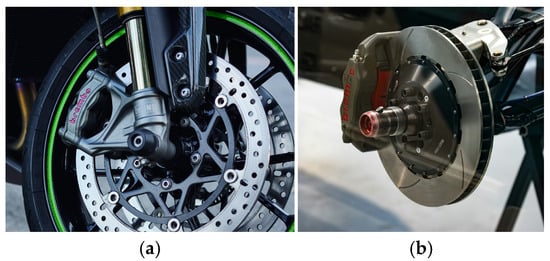
Figure 1.
Two common brake disc types: (a) motorcycle brake disc assembly [photo by Gaurav Kumar on Unsplash accessed 15 November 2025]; (b) brake disc assembly with ventilated rotor [photo by Toby Hall on Unsplash, accessed 15 November 2025].
In the context of Formula Student and other university-level racing competitions, floating brake disc systems are particularly attractive due to their weight-saving potential and high braking efficiency. Optimizing such systems involves not only selecting suitable materials but also simulating the mechanical stresses, rivet distribution, and ventilation patterns to achieve the desired compromise between thermal stability and structural integrity [11]. Modern approaches rely heavily on CAD/CAE tools, such as SolidWorks 2019 and finite element analysis, to evaluate disc deformation under mechanical loads before manufacturing prototypes [3,12,13].
Although floating discs are widely adopted in motorcycles and racing cars, design choices that appear minor—such as the number and spacing of fasteners (rivets/pins), local machining near the mounts, and ventilation hole patterns—jointly govern axial compliance, vibration tendency, and durability during braking events [14]. In university Formula Student applications, these parameters also interact with manufacturability and cost constraints, making a geometry-level analysis attractive before prototyping.
This work targets a Formula Student front brake and isolates the geometric/fastening design variables of a floating disc to quantify their effect on axial displacements under braking loads. Four disc variants (solid vs. ventilated; with/without machined sectors at the mounts) are studied across 3-, 4-, 5-, and 6-rivet configurations, using CAD/CAE to keep all other factors (pad geometry, force/torque levels, pitch circle, etc.) constant. Thermal and rotational effects are outside the present scope and are reserved for future work.
In the brake disc design, the idea of a floating brake disc appears more as a two-piece rotor, which is connected using rivets or pins (Figure 2), to manage the heat influence on the parts while hard braking [4,15]. A single-piece disc can be affected by distortion caused by heat generation during the braking process. One key design for a dual-component brake disc was developed as a result of the research on brake disc failures. These results allowed for the creation of a joint on the radial side of two discs, which transfers heat from one disc to the other while ensuring a radial floating of components in such a manner that there will be no tension induced due to heat. An important thing to take into account when designing a floating brake system is that the joint must only allow radial motion and must constrain the brake disc so that it will not move axially [16]; otherwise, axial play would lead to early failure, vibrations, fatigue in assembly elements, and less brake efficiency.
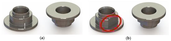
Figure 2.
Rivets used for braking disk assembly: (a) round rivets; (b) square drive system (two opposite parallel sides marked with a red circle).
The friction ring is connected to the bell via bobbins/rivets with parallel flats that act as guided sliding interfaces. The joint allows for controlled radial/hoop expansion of the ring under thermal loads while constraining axial motion to maintain pad–disc parallelism and avoid NVH. The contact faces are designed to slide in-plane with minimal shear transfer, preventing thermally induced stresses and hot spots.
On the other hand, using this system, the costs can be reduced: while the braking rotor would contain the special-purpose antifriction materials, the brake disc mounting support can be manufactured from standard steel or light alloy materials.
While the brake rotor is exposed to heat, the outer side will enlarge the circumference, while the inner side, where joint sections are located, will begin to shrink, leading to a greater load on rivets. As shown in the case of square drive rivets in Figure 2b, in the area highlighted in red, there are two opposing planar surfaces. These will permit a larger contact surface between elements while allowing for contact faces between brake rotor-rivet and brake disc support-rivet to allow them to slide relative to the other without inducing stress through elements [6,17].
As stated above, the main advantage of the brake disc solution based on a 2-component assembly is related to the efficient operation under all heat conditions due to a controllable distortion, with the possibility of keeping the mating surface of the disc in a parallel position in relation to the brake pads. Another advantage is represented by the possibility of using special antifriction material for the rotor while the brake disc mounting support can be manufactured using cheaper materials and technology. This also offers the possibility of manufacturing the brake disc support using aluminum alloy or other light alloy materials which would increase the heat dissipation from the brake rotor while increasing the ventilation of the brake rotor with a proper design. Also, there is an overall weight reduction with a system based on a floating brake disc compared to the classic design of a single-part brake disc.
Despite the advantages mentioned, this design for a floating brake disc also presents some disadvantages, such as expensive manufacturing costs caused by more manufacturing processes for the parts, more assembly operations, and high costs for materials.
This study aims to identify a technical solution for fastening the disc that reduces the number of rivets required in order to reduce the weight of the entire assembly, and correlate the surface area of the brake disc sector between two successive fastenings with the contact surface of the brake pad with the disc.
As emphasized in the classical engineering design literature, complex technical systems are best developed through an iterative but structured process, moving from task clarification to concept generation and then to detailed embodiment and validation. Thus, user, safety, manufacturing, and cost requirements are systematically integrated rather than handled via late ad hoc decisions, which reduces the risk of design changes in the prototype and testing stages [18].
These findings are consistent with application-focused reviews and industrial sources on floating brake discs, which describe two-piece rotors where a friction ring is connected to a carrier through bobbins or rivets, allowing for controlled radial sliding while preventing axial play. This architecture improves cooling, enables the use of advanced friction materials, and mitigates thermally induced distortion and fatigue, making floating discs attractive for high-performance motorcycles and racing cars [4,19,20].
Against this background, the present work does not introduce yet another generic hybrid algorithm. Instead, it contributes a problem-specific, high-fidelity, finite-element model and a structured design space for a Formula Student floating brake disc in which rivet number and layout, pad-to-spring length ratio, and ventilation patterns are treated as explicit geometric variables under realistic loading and safety constraints. This systematic framework isolates the geometric and fastening parameters that govern axial displacement and stability of the disc and is intended as a foundation for subsequent studies where metaheuristic and machine-learning-based optimization schemes of the type surveyed by Azevedo et al. [21] and Etim et al. [22] can be plugged in to explore the design space more broadly.
Accordingly, the central research hypothesis is that, for a given braking torque and pad contact geometry, an appropriate choice of disc topology (solid versus ventilated, with or without machined sectors) and the number and circumferential distribution of the floating rivets can significantly reduce the axial displacement dz of the friction ring while maintaining a satisfactory structural safety factor SF. In other words, geometry-level optimization of the fixture layout can be used as an effective lever to mitigate out-of-plane deformation of a floating brake disc without resorting to new materials or more complex caliper architectures.
2. Materials and Methods
A proper parameter to analyze the performance of a disc brake system is related to the friction between the materials and their wear process [23]. Many conventional brake systems use brake pads manufactured from friction materials, while the brake discs are usually made using cast iron. As a general characteristic, brake pads can be classified based on material composition as low metallic, semi-metallic, or non-asbestos organic. All three types of brake pads consists of 30 to 40 components, each of which contribute to a larger friction coefficient, less residual particle generation, heat dissipation, the need for bond additives, etc. [24,25,26,27]. A more simplified description for these 3 types of brake pads would classify them as low metallic brake pads, which offer good brake performance for a wide range of temperatures and high friction; semi-metallic brake pads, which are long lasting compared to the other types but they produce more noise during operation; and non-asbestos organic brake pads, which are long lasting with lower brake noise but are less effective at high temperatures [7].
In braking systems, a systematic approach is particularly important because the disc, pads, carrier, and fasteners jointly determine several conflicting objectives: thermal capacity, structural stiffness, NVH behavior, and unsprung mass. The brake-design monographs of Limpert and Day describe disc rotors as inherently multi-objective components whose geometry, materials, and mounting arrangement must be chosen together to ensure reliable torque generation, heat dissipation, and durability under repeated severe stops [7,8].
This work isolates structural contributors to out-of-plane warp. While braking couples thermal–mechanical–vibration–wear phenomena, we treat thermal effects parametrically via geometry (ventilation/cut-outs) and use axial displacement as a first-order indicator of judder risk [28]. Future work will couple transient CFD/FEA to resolve temperature fields and wear evolution [29].
The temperature range and friction coefficient are the key factors in brake pad selection, and they clearly distinguish street pads from dedicated track or racing compounds. [30,31] As illustrated in the chart below (Figure 3), street pads perform reliably within the typical temperature levels of daily driving but their effectiveness quickly declines—and can even fail—right around the point where track and race pads are only beginning to deliver their best performance.
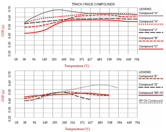
Figure 3.
Wilwood brake pad characteristics [8,30,31].
Temperature range and overall friction value are the primary considerations for pad selection. The pads must be capable of maintaining the proper amount of friction required for stopping within the temperatures on the track during the event. Then, the overall wear rate must be considered. For most asphalt and road race applications, compounds that are functional in the high temperature range over ≈ 538 °C are usually necessary [9].
As previously mentioned, the idea of designing a high-performance braking system for a race car used in Formula Student competitions led to the evaluation of design solutions for braking systems in order to determine the designs with high performance, but also possible problems that may be caused by premature wear of components. Although the floating brake disc solution has been used since the 1970s, there are still issues that have not been sufficiently analyzed. Therefore, starting from the design of an efficient braking system for a Formula Student race car, it was necessary to design a brake disc that meets the requirements and can be implemented in the whole wheel assembly; this involved modifications to components on the wheel hub and upright or other suspension components. After determining the dimensions of the friction surface between the disc and the brake pads, it is necessary to design the support disc so that the temperature variation in the braking disc does not affect the dimensions of the contact surfaces and that the heat dissipation is optimal to avoid shape deviations [32].
A workflow of the process of improving the fixture layout is presented in Figure 4, summarizing the steps from initial design to simulation and testing.
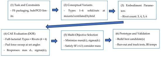
Figure 4.
Systematic design and roadmap for floating brake discs. Notes: dz = axial displacement (mm); SF = safety factor (-); DOE = design of experiments PCD = pitch circle diameter.
For this particular brake system, the brake disc is assembled through rivets to the support disc. In this study, we systematically evaluated how the number of rivets, the rivet pitch circle diameter, and the brake pad size influence the effects of mechanical loads on and axial deformation of the brake disc. This analysis aimed to determine the impact of rivet count on disc deformation and overall braking efficiency under a constant rivet diameter and consistent pad pressure.
It is assumed that the occurrence of deformations of the braking disc is closely connected with the position of the brake pads on the disc relative to the points of its attachment on the support disc. Figure 5 shows the assembled wheel that was used for the modelling. In order to obtain a symmetric wheel hub, which, in this case, is also the support disc for the brake disc, the initial design solution involved the use of a 4-rivet assembly for a wheel fixed on the hub with 4 screws. This type of assembly proved to be satisfactory in the tests performed with the prototype version but it was considered necessary to optimize the design of the braking system from this point of view.
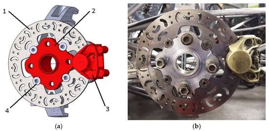
Figure 5.
Front wheel assembly with all components, including floating brake disc and caliper: (a) 3D model design (1—brake disc; 2—wheel hub; 3—brake caliper; 4—rivet); (b) real model.
All brake-disc variants were modeled in SolidWorks 2019 and analyzed with its built-in FEA solver. Four discs architectures were considered—Type 1 (solid friction ring), Type 2 (solid ring with reliefs near the rivet seats), Type 3 (ventilated ring), and Type 4 (ventilated ring with reliefs)—each evaluated with 3, 4, 5, and 6 rivets (v1a–v4d in Table 2). This yields 16 design cases for like-for-like comparisons of axial response under identical load cases. The geometric inputs that are common to all cases were as follows: outer disc diameter of 220 mm, inner friction diameter of 167 mm, rivet pitch-circle diameter of 110 mm, brake-pad mean contact-circle diameter of 193.5 mm, pad arc length of 48.49 mm, active disc areas of 16,075.91 mm2 (solid) and 15,171.13 mm2 (ventilated), and total pad–disc contact area of 2412.56 mm2.
Table 2.
Analyzed brake disc configurations.
In the experimental simulation, four input parameters (the type of brake disc described above) were taken into account in the research methodology, with each parameter having four levels (four design solutions for fastening with floating rivets, i.e., 3, 4, 5, and 6 rivets).
Meshing and solution settings
A curvature-based tetrahedral mesh was generated for each model. The reference mesh used in the comparisons comprises ~457,820 elements and ~720,367 nodes, with a characteristic element size of 2.38 mm in the friction band and rivet neighborhoods. This resolution was selected after verifying that further local refinement in the pad track and around the rivet seats does not materially change the peak axial displacement trends. Static, small-displacement solutions were computed for all cases.
Loading and contact idealizations
Two physically equivalent braking load descriptions were considered:
Normal loading with friction: A total normal force of N = 9800 N is applied through two rigid pads onto the friction track, with a dry friction coefficient μ = 0.6215 at the pad–disc interface. From these inputs, the nominal average normal pressure over the combined pad area is
and the corresponding tangential (friction) traction is
At the mean contact radius mm, this yields an equivalent braking torque of about
Pad locations were tested at the angular positions of 0°, 30°, 60°, 72°, 90°, 120°, 144°, 150°, 180°, 210°, 216°, 240°, 270°, 288°, 300°, and 360° so that the load also acts in the sectors just before and after each fastener. Contact was modeled as frictional and surface-to-surface, with the pads considered rigid (non-deformable) to isolate disc behavior.
Boundary conditions and constraints
The disc is constrained only at the rivet interfaces (the square-drive concept). Kinematically, these constraints (i) allow for radial sliding of the friction ring relative to the carrier (to emulate thermal growth accommodation), (ii) prevent axial motion at each connection (to avoid rattle and to reflect assembly pre-load), and (iii) suppress rigid-body motion by fully fixing one reference rivet in-plane. This reflects the design intent: radial compliance with no axial play [16]. The wheel-hub/bell was treated as the support body and, in this study, was not the focus of the deformation analysis.
Material models and properties
Unless otherwise noted, all solids were modeled as linear-elastic, homogeneous, and isotropic.
- Friction ring (disc): AISI 1020 steel, consistent with the tested prototype; elastic response is adequate for the reported safety factors and load levels in this study (Figure 6—1).
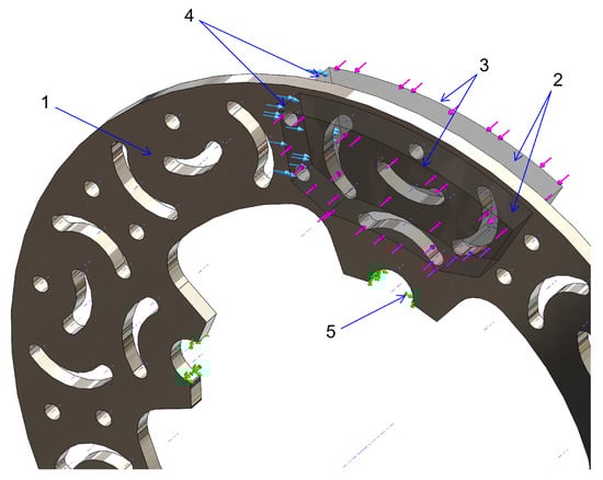 Figure 6. Brake disc analysis: 1—brake disc; 2—brake pads; 3—brake force applied through pads; 4—torque resulting while braking; 5—brake disc mounting points.
 - Rivets/pins: Steel, represented through the boundary constraints defined above (no separate fastener plasticity modeled) (Figure 6—5).
- Pads: Rigid, non-wearing platens with μ = 0.6215 against the disc surface (per the pad characterization used in the draft) (Figure 6—2).
For this study, the brake pads were modeled as rigid and non-deformable elements, thereby neglecting potential wear of the friction lining (Figure 6). For each variant, the solver returned full fields of displacement, reaction forces, strain, stress, and safety factor. The key comparison metric reported is the axial displacement within the braking band (since axial waviness directly drives vibration, brake-torque variation, and judder), while radial displacements—occurring largely in-plane—are not performance-limiting for pad contact. Across all models, the minimum safety factor ≥ 4.5, indicating adequate strength under the prescribed static loads.
In contrast to the prototype brake disc tested under real operating conditions—where it demonstrated both efficiency and reliability—the models developed for simulation were designed with an optimized configuration of ventilation channels. The arrangement of the vents was specifically conceived to ensure that, for all angular positions considered in the analysis, the contact surface between the disc and the brake pads remains consistent. Furthermore, the positioning of the ventilation holes was selected in such a way that, irrespective of the direction of rotation or the angular orientation of the plate relative to the disc, no resultant forces of differing magnitudes would be generated between cases. This uniformity was a critical design criterion, ensuring the stability and repeatability of the braking forces. An additional benefit of machining the ventilation holes is the consequent reduction in the overall mass of the brake disc, which contributes positively to vehicle dynamics and energy efficiency.
We used the same contact area at every angular pad position; therefore, the magnitudes of the resultant normal and tangential forces are identical across cases, and only their spatial distribution changes with pad angle. The equal-and-opposite reaction resultants are carried by the rivet constraints (the sum of reactions balances the applied resultants).
Under pad loading, the disc develops out-of-plane (axial) displacement; our FEA quantifies these fields and links them to rivet geometry. These stresses, in turn, may induce vibrations, which can compromise braking efficiency, accelerate thermal accumulation, and contribute to fatigue phenomena across assembly components, with rivets being particularly susceptible. Such effects highlight the importance of considering both structural and thermal behavior in brake disc design.
The previously developed prototype disc, which had been successfully tested in practice, was manufactured using AISI 1020 steel. Accordingly, the numerical simulations presented in this study were performed with the same material, ensuring consistency between the manufactured and 3D models. Nonetheless, it should be noted that alternative materials could lead to different outcomes. For example, certain alloys may produce smaller displacements under identical loading conditions, thereby offering improved structural performance.
Key assumptions and limitations
Thermal fields or the effects of rotation were not taken into account in the static structural analyses at this stage (to isolate the effects of geometry/fasteners on axial eccentricity).
Also, the brake pads were considered rigid bodies, without progressive wear, and friction was considered constant (μ = 0.6215) on the contact surface with the disc.
Rivet interfaces were idealized to block axial slip while permitting radial accommodation; detailed pin compliance and local contact stresses were not resolved in this stage.
These clarifications align the model description with the results that will be presented (Figure 7, Figure 8, Figure 9, Figure 10, Figure 11, Figure 12 and Figure 13), and make explicit how geometry and fastening strategy drive the observed axial-displacement reductions (notably for 5- and 6-rivet layouts, and for ventilated discs with profiled reliefs).
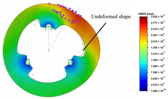
Figure 7.
Radial deformations.
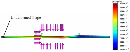
Figure 8.
Axial deformations.
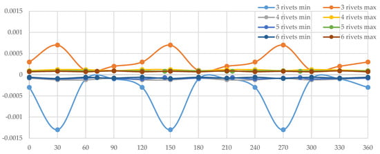
Figure 9.
Displacement along the axial direction for Disc Type 1. X-axis is the angular measurement; y-axis represents axial displacement measured in mm, where min represents displacement on one side and max represents displacement to the other side of the brake disc when it is in a relaxed state.
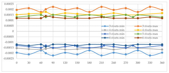
Figure 10.
Displacement along the axial direction for Disc Type 2. X-axis is the angular measurement; y-axis represents axial displacement measured in mm, where min represents displacement on one side and max represents displacement to the other side of the brake disc when it is in a relaxed state.
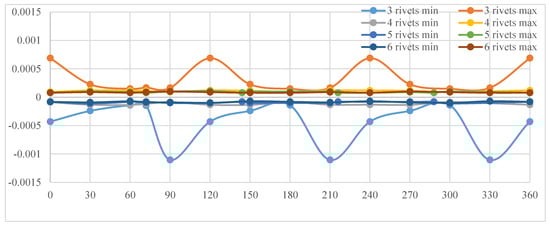
Figure 11.
Displacement along the axial direction for Disc Type 3. X-axis is the angular measurement; y-axis represents axial displacement measured in mm, where min represents displacement on one side and max represents displacement to the other side of the brake disc when it is in a relaxed state.
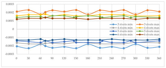
Figure 12.
Displacement along the axial direction for Disc Type 4. X-axis is the angular measurement; y-axis represents axial displacement measured in mm, where min represents displacement on one side and max represents displacement to the other side of the brake disc when it is in a relaxed state.
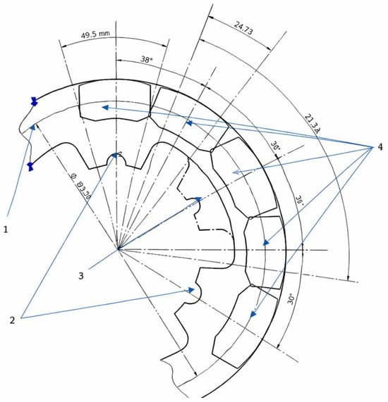
Figure 13.
Brake pad position during simulations (1—median radius; 2—rivet positions for 3-rivet mounting, 3—rivet positions for 6-rivet mounting; 4—different positions of braking pad during simulation (30° increments).
Recent work emphasized that there is no universally best optimization or learning algorithm; instead, the limitations of individual methods can often be mitigated by combining them into hybrid schemes. Azevedo et al. provide a systematic and bibliometric review of hybrid optimization–machine learning approaches, highlighting how metaheuristics and learning models can be coupled so that the strengths of one method compensate for the weaknesses of another [21]. Complementary surveys in structural and multidisciplinary optimization and structural engineering show a similar trend towards ML-enhanced optimization workflows and surrogate-assisted design in applications for structural and mechanical components [33,34].
These studies outline several recurring patterns—such as machine-learning-assisted metaheuristics, metaheuristic-assisted learning, and fully co-evolutionary hybrids—which are particularly relevant for expensive black-box models like high-fidelity finite element simulations. In this context, our FEA-based model of the floating disc can be naturally embedded in future work into a hybrid optimization framework where data-driven surrogates guide the exploration of the design space while metaheuristic searches refine promising regions [22].
There is no single best algorithm; instead, recent reviews show that hybrid optimization–machine learning schemes are being increasingly used to mitigate the limitations of individual methods and exploit their complementary strengths [21].
3. Results and Discussion
Static structural analyses were employed to determine displacements, reaction forces, strains, stresses, and the distribution of the safety factor across the proposed models. The focus of this investigation was directed primarily toward displacements along the axial axis, while other deformation modes and stress components, although present, were beyond the scope of the present study. For all the configurations examined, the minimum safety factor was greater than 4.5, thereby confirming that the proposed designs satisfy essential strength and reliability requirements under the applied loading conditions.
The graphical representations included in the study illustrate the mechanical response of one of the analyzed configurations when subjected to the prescribed loads. Specifically, Figure 7 depicts the radial displacements of the model, superimposed over the undeformed geometry, which is represented in grey. For the purposes of visualization, the deformation shape of the disc is exaggerated with a scaling factor of 2000, enabling a clearer interpretation of the radial displacement field.
In Figure 8, the same model is shown with displacements plotted in the axial direction. Here as well, the deformation pattern is presented with a magnification factor of 2000 to facilitate the observation of axial movements that would otherwise be imperceptible at true scale.
It is important to distinguish between the two deformation modes in terms of their implications for braking performance. Radial displacements, as presented in the first case, do not exert a detrimental effect on the braking process, since they occur primarily within the plane of rotation and do not compromise pad–disc contact uniformity. Conversely, axial displacements, particularly within the braking surface region, present a significant challenge. Such deviations give rise to vibrations that lead to uneven braking forces, resulting in non-linear system behavior and local overloading of components. This, in turn, can reduce braking efficiency, increase wear rates, and accelerate the onset of fatigue-related failures within the assembly.
All four proposed disc variants, corresponding to the four different fastening configurations, were systematically analyzed. Each configuration was evaluated for cases involving 3, 4, 5, and 6 fastening points, thereby allowing for a comparative assessment of their structural behavior under identical loading conditions. The results of these analyses were then centralized and organized according to the number of fixture points employed.
For clarity of interpretation, graphical representations were generated for each fastening configuration. These plots incorporate the performance results of all disc types presented in Table 1, enabling direct comparisons across disc designs and fastening strategies. Consequently, Figure 9, Figure 10, Figure 11 and Figure 12 illustrate the outcomes for the four fastening scenarios, highlighting the influence of fixture count on the mechanical response of the brake disc system.
From the charts presented above Figure 9, Figure 10, Figure 11 and Figure 12, it can be concluded that the configuration corresponding to Disc Type 1 with a three-rivet fastening solution exhibits the weakest structural performance. Specifically, this arrangement generates the largest axial deformations, which in turn induce a pronounced non-linear response in braking efficiency. Such behavior is undesirable as it compromises both stability and predictability of the braking process.
A closer examination reveals that the maximum deformations occur immediately after the passage of the brake pad in the direction of the fixture. More precisely, this phenomenon arises in the interval preceding the subsequent fastening point, where the radial sector of the braking surface presents the greatest unsupported length. This structural vulnerability becomes particularly evident at angular positions of 150° and 270°, where the spacing between rivets allows for increased disc deflection under loading.
By contrast, the alternative fastening solutions demonstrate a marked performance improvement. Configurations employing four, five, or six rivets exhibit a substantial reduction in axial displacements compared to the three-point assembly. Among these, the discs fixed with five and six rivets display the highest degree of linearity in their mechanical response, reflecting both improved stiffness and greater uniformity of load transfer. These results confirm the importance of optimizing the number of fastening points to minimize vibrational effects and ensure consistent braking efficiency.
Figure 10 shows that Disc Type 2 with a three-rivet fastening configuration demonstrates the least favorable axial performance relative to the other configurations. Nonetheless, when compared to the initial shape of the disc, without being subjected to any kind of stress and employing the same number of fastening points, a significant reduction in deformations is evident. This improvement is attributed to the presence of strategically placed cuts in the fastening region, which provide the disc with enhanced flexibility in the radial direction. As a result, this variant exhibits a notably more linear response than the first configuration analyzed, with substantially smaller radial deflections.
Consistent with the previous observations, the maximum deformations occur immediately after the brake pad passes the fixture zone. In this respect, the three-rivet assembly of Disc Type 2 retains the same characteristic deformation pattern as the earlier configuration, albeit with considerably diminished magnitudes.
For the remaining fastening alternatives, further improvements are evident. Configurations utilizing five and six rivets exhibit the most uniform response, with a pronounced reduction and flattening of deformation curves. These results underline the stabilizing effect of increased fastening points, which contribute to enhanced structural rigidity and a stronger tendency toward linearity in the overall mechanical behavior of the brake disc.
In the graph presented in Figure 11, Disc Type 3 with a three-rivet fastening configuration once again exhibits an oscillatory deformation pattern, similar to that observed in the initial case, though with a noticeably smaller amplitude. This reduction can be attributed to the introduction of ventilation holes distributed along the braking surface. While these apertures impart a degree of flexibility to the disc as a whole, their effect is considerably less pronounced than that produced by the cuts in the fastening region analyzed earlier. Nonetheless, the oscillatory behavior persists in the regions immediately following the passage of the brake pad beyond the fastening points, indicating localized structural responses to the applied loads.
For the alternative fastening solutions, a marked reduction in deformations is again observed when compared to the baseline three-rivet case. However, the extent of improvement is smaller than that achieved with the previously studied cut-pattern configuration, reflecting the more modest influence of ventilation holes on global structural stiffness. Furthermore, an increase in axial deformation is evident in the zones directly following the brake pad’s transition beyond the mounting area. This suggests that while the ventilated design contributes to improved cooling and reduced mass, it also introduces localized compliance that must be carefully managed in the context of braking stability and efficiency.
In the final configuration, represented by Disc Type 4 (as defined in Table 1), the brake disc integrates the fundamental design features of the three previously analyzed variants. The corresponding graph, shown in Figure 12, illustrates the axial deformation behavior under load. A comparative assessment of the results reveals that this configuration exhibits the smallest axial displacements of all the disc types studied, even though Disc Type 4 is, by design, the least structurally rigid. This outcome highlights the effectiveness of combining multiple design strategies into a hybrid configuration, which compensates for the inherent reduction in rigidity.
Notably, the configuration with three rivet fastenings demonstrates a significant decrease in axial deformation relative to the earlier three-point assemblies, with values approaching the average displacements observed in the discs fastened with four, five, or six rivets. Although an alternating, repetitive oscillation pattern is still visible immediately after the brake pad passes the rivet mount regions, the amplitude of this motion is substantially reduced compared to all previously examined configurations.
In particular, the three-rivet assembly once again displays oscillatory deformation behavior similar to that noted in the initial cases, but with a considerably smaller amplitude. This reduction can be explained by the presence of cooling and ventilation holes distributed across the braking surface, which not only contribute to thermal management but also introduce controlled flexibility into the disc. As in earlier observations, oscillations persist in the areas where the brake pad transitions beyond the fastening points, but their magnitudes are now minimal and do not significantly compromise the overall stability of the system.
For the other fastening alternatives, a pronounced reduction in axial displacements is also evident when compared to the baseline situation. However, the extent of deformation is slightly greater than that obtained with configurations incorporating profiled drilling patterns in the rivet mount regions. Furthermore, localized increases in axial deformation continue to appear immediately after the brake pad passes the mounting area. Despite this, the overall behavior of Disc Type 4 confirms the potential of hybrid designs to achieve a balance between effective cooling, reduced deformation, and consistent braking efficiency.
In Figure 13, the brake pads are shown successively positioned at the angular locations used in the simulations, namely 0°, 30°, 60°, 90°, and 120°. In these representations, the brake pads (denoted as element 4) are superimposed on the brake disc (element 2) in each of the five analyzed cases. For reference, the fastening system with six rivet grips (denoted as element 3) is also illustrated, enabling a direct comparison between the most unfavorable configuration and the most favorable one. This approach highlights the variation in structural response depending on the number of fixation points.
The geometric relationships between rivet spacing and pad dimensions play a critical role in determining load transfer and deformation behavior. Specifically, the length of the median arc of the contact surface between two rivet mounts, L, was calculated along the mean contact circle of the brake disc (with a diameter of 193.5 mm). For the three-rivet configuration, this length was determined to be 117.32 mm, whereas for the six-rivet configuration, the arc length was reduced to 24.73 mm. On the same mean circle, the arc length corresponding to one brake pad, lp, was measured as 48.5 mm.
These values, summarized in Table 3, provide a clear comparison of arc lengths between rivet mounts for each fastening configuration. The data underscore the significance of rivet spacing in constraining disc deformation: larger unsupported arc segments, as found in the three-rivet arrangement, allow for greater flexibility and larger axial displacements, while the shorter arc lengths in the six-rivet case ensure improved stiffness and more uniform load distribution.
Table 3.
Analyzed brake disc configurations.
Based on the analysis of the brake disc configurations presented above, it can be concluded that there exists a strong correlation between the length of the brake pad and the length of the arc sector between two successive fastening points. This geometric relationship exerts a decisive influence on the structural and functional response of the disc during braking.
When the ratio of the pad length to the arc length between mounts is less than unity, the system demonstrates an approximately linear behavior, irrespective of the absolute magnitude of the resulting deformations. Under such conditions, the contact between the pad and the disc remains sufficiently supported by adjacent fastening points, ensuring a more stable load distribution and reduced oscillatory effects.
Moreover, in configurations where profiled drillings are introduced in proximity to the clamps, the system’s flexibility is locally modified. This structural adaptation allows the pad-to-arc length ratio to increase to values approaching 1.5 while still maintaining acceptable levels of deformation and stability. Such results highlight the potential of combined geometric and structural strategies—specifically, the balance between fastening density, pad geometry, and drilled features—in improving the overall linearity and predictability of brake disc behavior under operational loads.
4. Conclusions
The study investigated geometric design options for a two-piece floating brake disc for a Formula Student vehicle under a quasi-static mechanical load (without thermal/rotational effects), keeping the caliper, pad spring, disc shell, and loads identical for all variants.
This study demonstrated that the improved geometric design of floating brake discs led to a decrease in the ratio between the length of the disc spring sector between two successive fastenings (L) and the length of the pad (lp), which means smaller axial deviations in the case of fastening with 4–6 rivets and, implicitly, improved braking stability. In contrast, the three-rivet configuration proved inadequate because it exhibited large axial deformations that could lead to non-linear braking.
Given the extreme conditions of Formula Student, all safety factor values were kept constant at over 4.5.
Future work will include extending the model to thermo-mechanical and rotating cases, accounting for pad material variability; characterizing joint compliance; and validating the results on a dynamometer using standardized procedures.
Overall, the study highlights that floating brake disc systems, when carefully designed taking into account rivet geometry, the pad-to-spring ratio, and ventilation strategies, can improve braking efficiency.
5. Limitations and Future Work
The present study is subject to several limitations that should be considered when interpreting the results. First, the finite element analysis is restricted to quasi-static mechanical loading and does not include thermal gradients or rotational effects; consequently, phenomena such as hot judder, fade, or thermally induced warpage are not captured in the current model [28,29]. Second, the pad–disc contact pressure distribution is idealized, and local effects related to wear, grooves, or pad shape evolution are neglected. Third, the material properties are assumed to be homogeneous, isotropic, and linear elastic, without considering temperature dependence, residual stresses, or manufacturing tolerances in the disc and mounting components. Fourth, the boundary conditions at the caliper and mounts are idealized to emphasize the influence of the disc topology and rivet layout; other caliper architectures or mounting strategies might modify the absolute values of the axial displacement and safety factor. Finally, the design space explored in the present design of experiments, although covering 16 configurations (4 disc types × 4 rivet counts), is not exhaustive with respect to all possible geometrical and fastening variants.
Future work will address these limitations by extending the model to fully thermo-mechanical and rotating conditions, incorporating more realistic pad–disc contact laws and material behavior, and performing dynamometer tests and quasi-static clamping experiments to quantitatively validate and potentially refine the numerical predictions.
Author Contributions
Methodology, T.M.; Software, M.T.D.; Validation, G.Ş.; Formal analysis, I.D.; Data curation, M.M.; Writing—original draft, C.C.D.; Writing—review & editing, C.C.D.; Supervision, N.D. All authors have read and agreed to the published version of the manuscript.
Funding
This research received no external funding.
Data Availability Statement
The original contributions presented in this study are included in the article. Further inquiries can be directed to the corresponding author.
Conflicts of Interest
The authors declare no conflict of interest.
References
- Chester Harley-Davidson. Floating Brake Rotors Split 7 Spoke. Available online: https://estore.chester-harley-davidson.co.uk/41500110-floating-brake-rotors-split-7-spoke-p119949.html (accessed on 22 July 2020).
- EBC Brakes. Apollo Braking Systems. Available online: https://ebc-brakes.ch/bremsanlagen-apollo/ (accessed on 22 July 2020).
- Belhocine, A.; Bouchetara, M. Thermo-mechanical behaviour of dry contact in disc brake rotor with a grey cast iron composition. Therm. Sci. 2012, 16, 529–546. [Google Scholar]
- EBC Brakes. Sportbike and Superbike Fully Floating Brake Rotors. Available online: https://www.ebcbrakes.com/products/floating-mc-rotors/ (accessed on 10 September 2025).
- Chu, Y.; Li, J.; Zhu, L.; Liu, Y.; Tang, B.; Kou, H. Microstructure Evolution of a High Nb Containing TiAl Alloy with (α2 + γ) Microstructure during Elevated Temperature Deformation. Metals 2018, 8, 916. [Google Scholar] [CrossRef]
- Zhao, S.; Yan, Q.; Peng, T.; Zhang, X.; Wen, Y. The braking behaviors of Cu-based powder metallurgy brake pads mated with C/C–SiC disk for high-speed train. Wear 2017, 376–377, 1616–1624. [Google Scholar] [CrossRef]
- Limpert, R. Brake Design and Safety, 3rd ed.; SAE International: Warrendale, PA, USA, 2011. [Google Scholar]
- Day, A.J. Braking of Road Vehicles; Butterworth-Heinemann: Oxford, UK, 2014. [Google Scholar]
- Blau, P.J. Compositions, Functions, and Testing of Friction Brake Materials and Their Additives; Oak Ridge National Laboratory Report, ORNL/TM-2001/64; Oak Ridge National Laboratory: Oak Ridge, TN, USA, 2001. [Google Scholar]
- Valvano, T.A.; Lee, K. An Analytical Method to Predict Thermal Distortion of a Brake Rotor; SAE Technical Paper 2000-01-0445; SAE International: Warrendale, PA, USA, 2000. [Google Scholar]
- Talati, F.; Jalalifar, S. Analysis of heat conduction in a disk brake system. Heat Mass Transf. 2009, 45, 1047–1059. [Google Scholar] [CrossRef]
- Ahmad, F.; Vishvajeet; Sethi, M. Thermo-mechanical analysis of disk brake using finite element analysis. Mater. Today Proc. 2021, 47, 4316–4321. [Google Scholar] [CrossRef]
- Kalaiarasan, K.; Prakash, S.; Vinoth Kumar, M. Computation Design and Analysis of Brake Disc with Sandwich Ventilated Structure; SAE Technical Paper 2020-28-0350; SAE International: Warrendale, PA, USA, 2020. [Google Scholar]
- Liu, P.; Zheng, H.; Cai, C.; Wang, Y.Y.; Lu, C.; Ang, K.H.; Liu, G.R. Analysis of Disc Brake Squeal Using Complex Eigenvalue Method. Appl. Acoust. 2007, 68, 603–615. [Google Scholar] [CrossRef]
- EBC Brakes Direct. Fully-Floating 2-Piece Brake Rotors. Available online: https://ebcbrakesdirect.com/fully-floating-2-piece-brake-rotors (accessed on 10 September 2025).
- Floating Brake Rotor Assembly with Non-Load Bearing Pins. US Patent 6,957,726 B2, 25 October 2005. Available online: https://patents.google.com/patent/US6957726B2/en (accessed on 10 September 2025).
- EBC Brakes. SD-System Square Drive. Available online: https://www.ebcbrakes.com/technical_ebc_brakes_blog/sd-system-square-drive-and-how-it-works/ (accessed on 10 September 2025).
- Pahl, G.; Beitz, W.; Feldhusen, J.; Grote, K.-H. Engineering Design: A Systematic Approach, 3rd ed.; Springer: London, UK, 2007. [Google Scholar] [CrossRef]
- Joshi, A.G.; Bharath, K.N.; Basavarajappa, S. Recent progress in natural composite friction materials for automotive brake pads—A review. Tribol. Mater. Surf. Interfaces 2023, 17, 237–259. [Google Scholar] [CrossRef]
- Day, A.J.; Tirovic, M.; Newcomb, T.P. Thermal effects and pressure distributions in brakes. Proc. Inst. Mech. Eng. Part D J. Automob. Eng. 1991, 205, 199–205. [Google Scholar] [CrossRef]
- Azevedo, B.F.; Rocha, A.M.A.C.; Pereira, A.I. Hybrid approaches to optimization and machine learning methods: A systematic literature review. Mach. Learn. 2024, 113, 4055–4097. [Google Scholar] [CrossRef]
- Etim, B.; Al-Ghosoun, A.; Renno, J.; Seaid, M.; Mohamed, M.S. Machine Learning-Based Modeling for Structural Engineering: A Comprehensive Survey and Applications Overview. Buildings 2024, 14, 3515. [Google Scholar] [CrossRef]
- Straffelini, G. Friction and Wear: Methodologies for Design and Control; Springer: Cham, Switzerland, 2015. [Google Scholar]
- Bijwe, J. Composites as friction materials: Recent developments in non-asbestos fibre reinforced friction materials—A review. Polym. Compos. 1997, 18, 378–396. [Google Scholar] [CrossRef]
- Kim, S.J.; Cho, M.H.; Cho, K.H.; Jang, H. The effect of phenolic resin, potassium titanate, and aramid pulp on the friction and wear of brake friction materials. Wear 2008, 264, 204–210. [Google Scholar] [CrossRef]
- Krishnan, G.S.; Kumar, S.; Suresh, G.; Akash, N.; Sathish Kumar, V.; David, J.P. Role of metal composite alloys in non-asbestos brake friction materials—A solution for copper replacement. Mater. Today Proc. 2021, 45, 926–929. [Google Scholar] [CrossRef]
- Jadhav, S.P.; Sawant, S.H. A review paper: Development of novel friction material for vehicle brake pad application to minimize environmental and health issues. Mater. Today Proc. 2019, 19, 209–212. [Google Scholar] [CrossRef]
- Park, J.H.; Park, T.W.; Lee, J.H.; Cho, M.H. Hot judder simulation of a ventilated disc and design of an improved disc using sensitivity analysis. Int. J. Automot. Technol. 2014, 15, 1–6. [Google Scholar] [CrossRef]
- Gao, C.H.; Lin, X.Z. Transient temperature field analysis of a brake in a non-axisymmetric three-dimensional model. J. Mater. Process. Technol. 2002, 129, 513–517. [Google Scholar] [CrossRef]
- Wilwood Engineering. Brake Pads Compound Overview and Bedding Instructions (FL227). Available online: https://wilwood.com/PDF/Flyers/fl227.pdf (accessed on 10 September 2025).
- Wilwood Engineering. Brake Pad Compound Selector. Available online: https://www.wilwood.com/BrakePads/BrakePadsApp (accessed on 10 September 2025).
- Jaenudin, J.; Pratama, M.; Suhery, S. Thermal analysis of disc brakes using finite element method. AIP Conf. Proc. 2017, 1788, 030028. [Google Scholar] [CrossRef]
- Ramu, P.; Thananjayan, P.; Acar, E.; Bayrak, G.; Park, J.W.; Lee, I. A survey of machine learning techniques in structural and multidisciplinary optimization, Structural and Multidisciplinary Optimization. Struct. Multidiscip. Optim. 2022, 65, 266. [Google Scholar] [CrossRef]
- Málaga-Chuquitaype, C. Machine Learning in Structural Design: An Opinionated Review. Front. Built Environ. Sec. Earthq. Eng. 2022, 8, 815717. [Google Scholar] [CrossRef]


Disclaimer/Publisher’s Note: The statements, opinions and data contained in all publications are solely those of the individual author(s) and contributor(s) and not of MDPI and/or the editor(s). MDPI and/or the editor(s) disclaim responsibility for any injury to people or property resulting from any ideas, methods, instructions or products referred to in the content. |
© 2025 by the authors. Licensee MDPI, Basel, Switzerland. This article is an open access article distributed under the terms and conditions of the Creative Commons Attribution (CC BY) license.