Abstract
Spline couplings endure various external loads during operation, which induce complex variations in contact surfaces and significantly affect their stiffness behavior. This research focuses on a specific spline coupling to analyze its nonlinear stiffness characteristics and underlying mechanisms. Employing the finite element method, a simulation model is developed to investigate the nonlinear load-dependent stiffness changes under multiple contact surfaces. The study investigates the nonlinear stiffness characteristics of the spline coupling through sensitivity analysis of stiffness to contact surfaces and contact state changes, and reveals the patterns of contact state evolution. The analysis indicates that as external loads increase, the spline coupling stiffness decreases significantly. Variations in the contact states of each surface induce nonlinear stiffness variations, with centering surface B (the cylindrical centering surface on the right side of the spline coupling) exhibiting the most substantial influence on nonlinear stiffness changes. Furthermore, the effects of centering surface clearance, applied torque, and friction coefficients across contact surfaces on the spline coupling stiffness are examined. Stiffness increases as clearance decreases and torque increases, while friction coefficients exhibit a negligible impact on stiffness performance.
1. Introduction
The connection structures widely used in aircraft engine rotors primarily include spline couplings, end-tooth connections, and bolt/pin connections. Among these, the spline coupling structure offers advantages such as high load-bearing capacity, compact design, ease of installation and disassembly, and high reliability. It is extensively applied in connecting the fan shaft and low-pressure turbine shaft within the low-pressure rotor of aircraft engines [1]. The key structural features of a spline coupling are: torque transmission via splines, cylindrical surface centering, and nut clamping. Centering is achieved through a specific interference fit on the cylindrical surfaces, while torque is transmitted through the spline section. The nut or tie rod clamping restricts axial relative movement between the two connected shafts, thereby enhancing connection stiffness.
In recent years, numerous domestic and international scholars have conducted extensive research on the stiffness characteristics and contact damage of this connection. To determine the stiffness of the spline joint, analytical methods and finite element methods are two commonly used approaches. Liu et al. [2] and Wu et al. [3] established three-dimensional finite element models of spline couplings, analyzing the influence of radial force, mating relationship, centering surface spacing, and width on the overall linear and angular stiffness of the structure. Results indicate that the stiffness characteristics exhibit distinct nonlinear variations. Zhu et al. [4] considered stiffness models incorporating both tooth surface engagement and centering surface contact. Li et al. [5] analyzed the nonlinear characteristics of bending stiffness and its underlying mechanisms through finite element modeling; Zhao et al. [6] modeled and numerically simulated the contact stiffness of cylindrical centering surfaces in spline joints based on Hertz contact theory and elastic contact models for rough surfaces; Hong et al. [7,8,9] established a semi-analytical model for solving tooth loads and investigated stress distribution on contact tooth surfaces under torque loading; Curà et al. [10,11,12,13,14] investigated the stiffness, fatigue damage, and micro-motion wear damage patterns of spline joints through numerical simulation methods, supplemented by experimental measurements.
Finite element analysis can precisely account for the complexity of spline couplings. However, this also necessitates a larger number of mesh divisions for the finite element model, resulting in significant computational time. Furthermore, divergence issues arise during calculations involving nonlinear contact problems. Consequently, some scholars have conducted numerical analysis studies to investigate the characteristics of spline couplings. Hong et al. [15] established a semi-analytical load distribution model for spline couplings, proposing a general calculation formula for spline couplings. Their research revealed uneven load distribution and nonlinear stiffness variation with rotational angle. Marmol et al. [16] derived the stiffness of spline couplings from spline deformation, but this study assumed uniform axial load distribution across the contact surface, introducing significant limitations. Zhao et al. [17] calculated the stiffness of individual splines, revealing pronounced nonlinear characteristics under high loads. Yu et al. [18] addressing limitations of previous methods, employed a slicing approach to establish an analytical model for calculating the stiffness of flexible spline couplings, accounting for the varying meshing states of individual teeth under external loads; Jiang et al. [19] considered the influence of friction on the spline couplings, thereby deriving an analytical stiffness calculation model incorporating friction effects. Huang et al. [20] further optimized Yu’s analytical model, addressing energy redundancy in the energy method and considering the stiffness of spline couplings under misalignment conditions. All these studies employed the energy method to investigate tooth deformation and meshing stiffness [21,22,23]. Zhang et al. [24] further developed a stiffness calculation model for initially misaligned spline couplings, but the model assumes smooth frictionless conditions, which significantly deviates from real-world scenarios.
From the above literature review, it can be concluded that most studies focus on a single aspect of spline couplings, such as tooth contact conditions or cylindrical surface contact issues. However, research on the nonlinear stiffness behavior of these structures remains scarce. In reality, spline couplings transmit multiple loads including axial forces, radial forces, bending moments, and torsional moments. This results in complex states such as separation, sliding, and sticking across different contact surfaces. Conventional studies often neglect tooth contact conditions, thereby overlooking the influence of tooth meshing on the nonlinear characteristics of these connections. Therefore, further research is needed to investigate the influence of tooth surface contact conditions on the stiffness of spline couplings. Given this, this paper takes a specific type of aviation engine spline coupling as its research subject. It first examines the mechanism of nonlinear stiffness in spline couplings under the coupled effects of radial loads and torque. Based on the finite element contact method, a finite element model accounting for the influence of tooth surface contact states is established. Subsequently, the nonlinear stiffness characteristics of the structure under load are analyzed. Finally, the influence patterns of key characteristic parameters on stiffness are investigated.
The article is structured as follows: Section 2 derives the theoretical model of the spline couplings and describes the computational methodology for its stiffness; Section 3 establishes the finite element model of the spline couplings and undertakes a nonlinear analysis of the stiffness; Section 4 is dedicated to examining the influence of key characteristic parameters on the spline coupling stiffness; finally, Section 5 summarizes some brief conclusions.
2. Stiffness Calculations of the Spline Coupling
A typical spline coupling in aircraft engines is generally used to connect the turbine rotor and fan rotor, with its structure shown in Figure 1. The entire spline coupling employs front and rear cylindrical contact surfaces for centering, thereby ensuring shaft coaxiality. The right-end contact surface of the turbine shaft typically uses a clearance fit. Axial preload is applied via a locking nut, which facilitates axial compression of the low-pressure turbine shaft and the fan shaft at the spline coupling’s right end, thereby enhancing the overall structural stability of the joint. The primary distinction between the spline coupling model used herein and conventional models lies in the application of preload through a tie-rod rotor, centering surface A is located on the mating cylindrical surface on the left side of the fan shaft and turbine shaft; centering surface B is located on the mating cylindrical surface on the right side of both shafts, as illustrated in Figure 2. During actual operation, the spline coupling bears axial tensile and compressive loads transmitted from components such as fans and turbines. When bending deformation occurs due to unbalanced forces, gyroscopic moments, and other external loads, the front and rear cylindrical surfaces achieve centering while withstanding shear forces and bending moments. The spline engagement zone primarily accommodates torsional loads.

Figure 1.
Traditional spline coupling structure.

Figure 2.
Structure of the spline coupling used in this article.
Under external loads, the force distribution of the spline coupling is shown in Figure 3. As the left and right sides of the spline coupling are connected to the fan rotor and turbine rotor, respectively, the combined action of the tie rod rotor and fan rotor subjects the fan shaft to a rearward load while the turbine rotor experiences a forward load. Thereby inducing axial compression at the right end. When the right-end centering surface is in a clearance fit, external loads cause the low-pressure turbine shaft to undergo bending deformation. If this deformation exceeds its initial clearance, contact occurs between the low-pressure turbine shaft and the right-end contact surface of the fan. Both bear the resulting contact forces.

Figure 3.
Mechanical model of a spline coupling.
After enduring bending loads and radial forces, the spline coupling will undergo bending deformation and angular displacement, as shown in Figure 4. The bending stiffness characterized by bending deformation and angular displacement is divided into linear stiffness and angular stiffness, defined by the following formulas:

Figure 4.
Schematic diagram of deformation in a spline coupling: (a) bending deformation; (b) angular deformation.
2.1. Shaft Stiffness
When calculating the bending stiffness of fan shaft and turbine shaft, one end of the shaft can be fixed and treated as a simply supported beam of uniform cross-section. Given the beam’s bending stiffness as EI and its length as L, M = FL, M is the bending moment applied to the right end of the beam. When subjected to a load F at the right end, the resulting deflection is:
Substituting into Equation (1) yields:
Thus:
The sectional moment of inertia of the shaft is defined as I, where R1 is the outer diameter of the shaft and R2 is the inner diameter of the shaft. E is the elastic modulus, and L is the length of the shaft.
2.2. Cylindrical Surface Contact Stiffness
The stiffness of cylindrical contact surfaces can be determined using an elastic foundation model [25]. After simplifying the contacting objects as shown in Figure 5, the simplified model comprises an elastic contact layer and a stiffened layer. Since the contact surfaces are cylindrical, establish the coordinate system shown in Figure 6. Circle 1 represents the inner cylindrical surface of the fan shaft, while Circle 2 represents the outer cylindrical surface of the turbine shaft. Under the radial force acting on the right end of the turbine shaft, Circle 1 remains stationary while Circle 2 moves downward by a distance u. The coordinates of the intersection point between the two cylindrical surfaces can be determined as follows [25]:

Figure 5.
Cylindrical surface contact model.
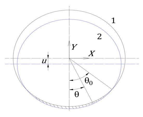
Figure 6.
Schematic diagram of cylindrical surface contact.
Thus, the coordinates of the intersection point are obtained as:
The gap between the two cylindrical surfaces is: . Substituting:
Let , denote the radii of curvature of the outer and inner cylindrical surfaces in the same radial direction. Approximating that the centers of curvature of both surfaces lie at the center of the outer cylindrical surface:
Thus:
Thus, the contact pressure per unit area on the contact surface can be determined by the difference between and :
Therefore, the total pressure can be obtained as:
Thus, the contact stiffness can be obtained:
Here, c is the coefficient determined by the contact form.
2.3. Tooth Stiffness
2.3.1. Elastic Deformation of Tooth Surfaces
Treat the tooth surface as a cantilever beam with variable cross-section [4], as shown in Figure 7. Divide it into several infinitesimal elements, each of which can be regarded as a cantilever beam. Taking one infinitesimal element i as an example, its thickness is Li, the distance from the load application point is Sij, and its cross-sectional area is Ai. The cantilever beam model is shown in Figure 8.
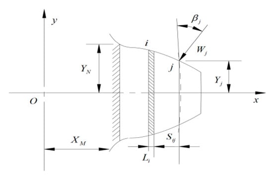
Figure 7.
Variation section beam.
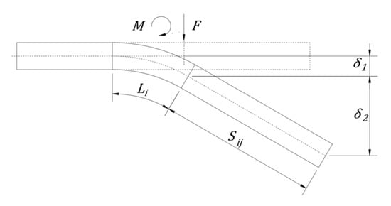
Figure 8.
The elastic deformation with lateral force and moment.
From the equations of the rotation and deflection of a beam with constant cross-section [4]:
When :
Under the action of the equivalent bending moment , elastic deformation of the tooth surface is obtained [4]:
2.3.2. Shear Deformation of the Tooth Surface
For the cross-section of a cantilever beam, the shear stress is expressed as:
F is shear force, ; s is stress non-uniformity coefficient; Ai is cross-sectional area.
Shear deformation is expressed as:
and for a rectangular cross-section s = 1.2,
Thus, the total elastic deformation is determined to be [4]:
According to the empirical formula, the contact deformation of the tooth surface is given by [26]:
Additional deformation caused by root elasticity [4]:
Therefore, the total deformation of the entire tooth surface is:
Thus, the tangential stiffness of a single pair of teeth is obtained as:
The overall meshing stiffness model of the spline coupling is shown in Figure 9. Contact point i lies on the pitch circle, which determines i. In the figure, Fni and ni represent the normal force and normal displacement of the contact surface, respectively. i denotes the vertical displacement of the i-th tooth and represents the total vertical displacement of the entire joint. From the preceding derivation, it follows that the direction of external force F corresponds to the normal stiffness. Therefore, the tangential stiffness KTi is effectively equivalent to the normal stiffness Kni, allowing the normal force to be directly calculated from KTi.
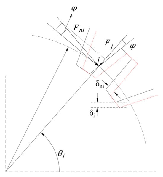
Figure 9.
Total engagement stiffness model.
Normal displacement of the i-th tooth:
where represents the vertical displacement of the i-th tooth, , and denotes the total vertical displacement of the joint.
The normal force at the i-th tooth is:
Vertical force on the i-th tooth:
Thus, the vertical force on the joint is obtained:
Therefore, the total stiffness can be obtained as:
where n is the number of meshing tooth pairs in the spline joint.
Therefore, the total stiffness of the spline joint can be obtained as:
Here K1 and K2 represent the stiffness of the fan shaft and turbine shaft, respectively; denotes the stiffness of the centering surface A; denotes the stiffness of right centering surface B; and Kn denotes the meshing stiffness of the teeth.
The above derivation establishes theoretical formulas for calculating the stiffness of each component in a spline coupling, forming the physical basis for analyzing its overall stiffness characteristics. Therefore, the following section will establish a finite element model based on the geometric and material parameters determined by the theoretical model to conduct an in-depth investigation of this nonlinear mechanism.
3. Results and Discussions
3.1. Finite Element Model
As noted in the literature [27], linear stiffness and angular stiffness share the same physical essence and exhibit congruent variation trends. Therefore, subsequent discussions will focus solely on linear stiffness. The model employed in this study diverges considerably from conventional configurations in several key aspects. First, the preload is introduced via the rod rotor rather than the locking nut used in conventional models. Second, this model utilizes only a single pre-tightening surface to secure the spline coupling, whereas traditional models utilize dual clamping surfaces. Furthermore, the pre-tightening surface in this model exerts pre-tightening pressure on the right side of the spline coupling, whereas traditional model apply pre-tightening pressure from the left side via two such surfaces. In traditional spline couplings, centering surface A maintains a constant zero-initial clearance state due to stable engagement, and thus its influence can be justifiably neglected in the study of overall stiffness behavior. However, in the proposed model, the effect of centering surface A on the stiffness of the spline coupling must be considered.
For the spline coupling under investigation, the influence of the threaded connection is neglected. A finite element model of the spline coupling is developed based on its structural parameters. The meshing is performed using SOLID186 hexahedral elements. Structural constraints, loads, and contact settings are depicted in Figure 10. During the simulation, the left end of the fan shaft is fully fixed, while a load is applied to the right end of the low-pressure turbine shaft. The contact surface employs the CONTA174 element and the target surface uses the TARGET170 element to simulate the meshing contact between the contact surface and the teeth. The initial friction coefficient for the contact surfaces is defined as 0.15. The spline connection parameters are listed in Table 1.
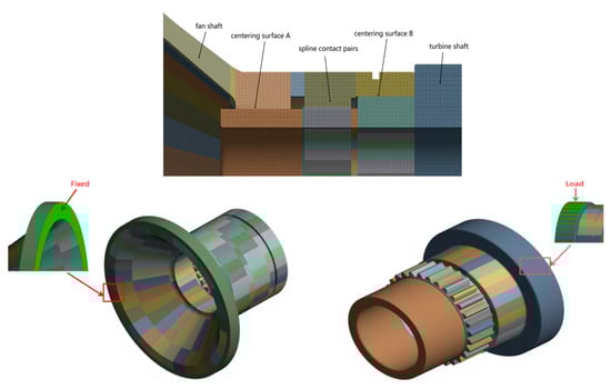
Figure 10.
Finite element model of the spline coupling.

Table 1.
Spline coupling structural parameters.
3.2. Stiffness Nonlinear Characteristics
3.2.1. Sensitivity of Stiffness to Contact Surface
To investigate the key factors contributing to the nonlinear stiffness behavior of the spline coupling. We established a reference condition: within the finite element model, the contact properties of specific surfaces (such as pre-tightening surface or centering surfaces A or B) were set to “Bonded” to simulate an ideal scenario where these surfaces are fully fixed and exhibit no state changes. The corresponding variation in stiffness with respect to applied load is illustrated in Figure 11.

Figure 11.
Effect of different contact surfaces on stiffness.
As shown in the Figure 11, after binding the contact surfaces, nonlinearities arising from contact behavior are effectively eliminated. Therefore, the stiffness of the spline coupling remains nearly constant and exhibits an approximately linear relationship with increasing load, except for a slight decrease at low loads caused by contact variations on other surfaces. This also indicates that the nonlinear effect of contact state changes on the stiffness of the spline coupling is quite significant. Further analysis of stiffness values after binding individual contact surfaces reveals a marked increase in spline coupling stiffness under identical loading conditions. Among these, the stiffness change after binding centering surface B is the most pronounced when considering contact effects. Therefore, the variation in its contact state exerts the most substantial impact on stiffness behavior.
A comprehensive analysis of the stiffness behavior of spline couplings under the influence of multiple contact surfaces is performed. To assess the sensitivity of stiffness to different contact surfaces, the sensitivity is defined as the difference between the stiffness when the contact state of a particular surface is neglected and the stiffness when all surfaces of the spline coupling are in full contact. The formula is defined as:
Here, Ka represents the actual stiffness of the spline coupling under full contact conditions, while Kl denotes the stiffness when variations in the contact state of a specific surface are disregarded. Based on Figure 11 and Equation (34), the sensitivity of the spline coupling stiffness to contact surfaces is shown in Figure 12.
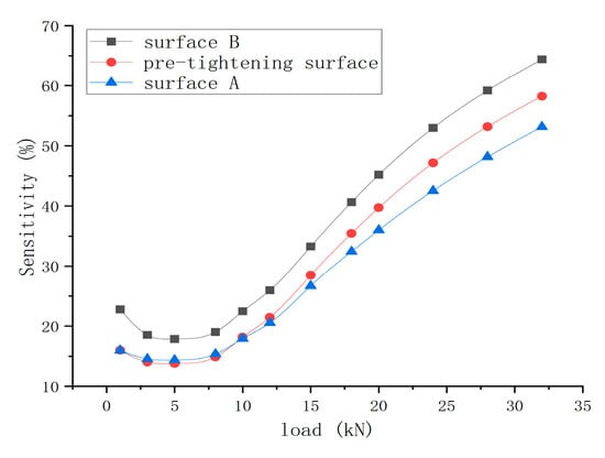
Figure 12.
Sensitivity of stiffness to different contact surfaces.
The results demonstrate that changes in contact states introduce a nonlinear effect on the stiffness behavior of the spline coupling. Moreover, as the load increases, the stiffness exhibits heightened sensitivity to contact state variations across the surfaces. The stiffness shows greater sensitivity to centering surface B, which is consistent with the notable increase in overall stiffness observed after binding this surface, as shown in Figure 11.
3.2.2. Nonlinear Influence of Contact Distance on Stiffness
Analysis of the nonlinear influence of cylindrical centering surface contact on the stiffness of the spline coupling structure: For centering surfaces A and B, one surface maintains a clearance of 0 mm, while the initial clearance of the other surface is set to −0.02 mm, 0 mm, and 0.02 mm, respectively. The variation in stiffness with load under different centering surface tightness is shown in Figure 13. It can be observed that under identical load levels, the stiffness of the spline coupling increases with a tighter cylindrical fit. When the contact clearance of centering surface A increases from −0.02 mm to 0.02 mm under 20 kN, the stiffness increases by approximately 14.79%. In contrast, a similar variation in the contact clearance of centering surface B results in a stiffness increase of approximately 41.28% under the same load. This indicates that changes in the contact state of centering surface B have a more pronounced influence on structural stiffness. Furthermore, the trends in stiffness variation under different initial clearances are generally consistent: stiffness gradually decreases with increasing load until it eventually stabilizes. After load intensification reaches a certain threshold, stiffness stabilizes; however, residual differences persist among configurations with different initial clearances. This discrepancy stems from discontinuities in the contact surface under varying gaps. Consequently, structural discontinuities induce changes in deformation and contact states during loading, imparting nonlinear characteristics to the coupling’s stiffness behavior.
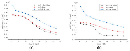
Figure 13.
Effect of different contact distances on stiffness for different centering surfaces: (a) surface A; (b) surface B.
When the initial clearances of centering surfaces A and B is set to −0.02 mm and 0 mm, respectively, the contact state of the centering surfaces becomes unstable under low loads. The deformation caused by the load is insufficient to compensate for the initial clearance. However, due to the influence of contact between the tooth surfaces and other contact surfaces, the stiffness of the spline connection does not show a significant reduction at loads below 8 kN. When the initial contact clearance of centering surface B is −0.02 mm, a pronounced decline in stiffness occurs between 10 kN and 15 kN. This behavior arises because centering surface B undergoes a transition from a separated state to gradual contact under load, but the initial contact remains unstable, thereby affecting the stiffness of the spline coupling. Beyond a load of 18 kN, the contact on centering surface B gradually stabilizes. The stiffness no longer changes with variations in the contact surface. It is evident that, within the given structural parameters, variations in load and the mating condition of the centering surfaces significantly affect the stiffness of the spline coupling.
3.3. Change in Contact State at Contact Surfaces
The essence of the non-rigid linear characteristics in spline couplings stems from structural deformation under loading, which alters the contact state and load distribution across all contact surfaces. To investigate the nonlinearity of these structures, the contact behavior of centering surfaces A and B were extracted using finite element analysis, focusing on the nonlinear influence of loading on stiffness. The contact states of centering surfaces A and B under different loads during clearance fits are illustrated in Figure 14 and Figure 15, respectively. The meanings represented by the contact surface states are as follows: yellow indicates separation, orange indicates sliding, and red indicates sticking. These figures elucidate the evolution of contact state and contact pressure on each surface as a function of applied load and fit configuration. Such analysis facilitates an in-depth understanding of the contact behavior across individual surfaces, thereby identifying the causes of nonlinear stiffness in the spline couplings.
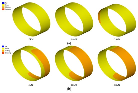
Figure 14.
Contact state of different centering surfaces under centering surfaces A clearance fit: (a) surface A; (b) surface B.
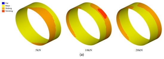
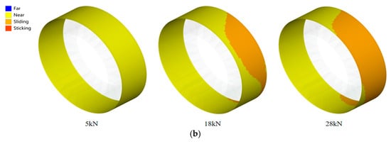
Figure 15.
Contact state of different centering surfaces under centering surfaces B clearance fit: (a) surface A; (b) surface B.
As shown in Figure 14 and Figure 15, the distribution of contact states undergoes significant changes as the load increases. Under clearance fit conditions, the contact state of centering surface B exhibits more pronounced variations with load changes compared to centering surface A. For centering surface A under clearance fit, a limited sliding region emerges only when the load reaches 28 kN. Therefore, the effect on its contact state under clearance fit is not significant. This also explains why the stiffness curve variation in centering surface A under clearance fit relative to zero clearance in Figure 14a is not pronounced. For both clearance and zero-clearance fits, the contact state remains largely stable under low loads, with minimal variation, resulting in only marginal changes in spline coupling stiffness. In contrast, under interference fit conditions, the initial pre-compression of the centering surfaces induces more pronounced alterations in contact state even at low load levels. This leads to a discernible trend in stiffness variation in the spline coupling from the onset of loading.
Comparing the contact states of centering surface B under different loads during gap contact reveals that at 5 kN, the surface remains separated. Consequently, its influence on stiffness is negligible, with changes in stiffness attributable solely to variations in other contact surfaces. As the load increases, localized sliding regimes emerge on centering surface B at 18 kN and further expand with additional loading. Conversely, the sliding area on centering surface A gradually decreases with increasing load. This contributes to improved overall deformation coordination of the structure, explaining why the gap fit in Figure 13b gradually stabilizes in the latter stages. Contact pressure is shown in Figure 16. Although the contact area within the slip zone of centering surface A decreases, the maximum contact pressure exhibits a progressive increase. This indicates that as load increases, separation occurs on centering surface A, leading to contact localization and elevated maximum pressure. For centering surface B, the contact area expands progressively under higher loads, resulting in a corresponding upward trend in maximum contact pressure.
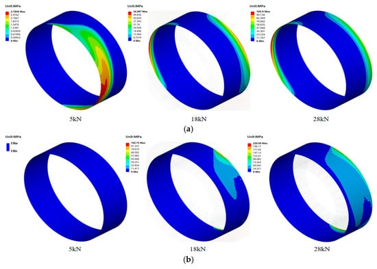
Figure 16.
Contact pressure between different centering surfaces under centering surfaces B clearance fit: (a) surface A; (b) surface B.
4. Effects of Parameters
4.1. Effect of Friction Coefficient
The friction coefficient of the spline coupling in aircraft engines exhibits significant variation under different assembly standards and operating conditions. As a critical parameter ensuring the stability of the spline coupling, it influences the structural stiffness characteristics. When the initial clearance between the low-pressure turbine shaft and fan shaft at centering surfaces A and B is set to 0 mm, and under otherwise unchanged operating conditions of the contact pairs, the friction coefficients of each contact surface were systematically varied to 0.1, 0.2, and 0.3. The stiffness of the spline coupling under different friction coefficients is calculated, and the resulting variation trends are shown in Figure 15. The results reveal that the trends in stiffness variation across different friction coefficients are generally consistent among the various contact surfaces. At lower load levels, the friction coefficient has a negligible effect on the stiffness of the spline coupling. However, under high-load conditions, the stiffness exhibits a moderate increase with rising friction coefficient.
For the centering surface, an increase in the friction coefficient of surface B from 0.1 to 0.3 under a load of 20 kN resulted in a corresponding rise in stiffness from 2.572 × 10⁵ N/mm to 2.651 × 10⁵ N/mm, representing an approximate 2.98% increase, as illustrated in Figure 17b. The contact state and contact pressure of centering surface B under different friction coefficients are shown in Figure 18. It can be observed that the friction coefficient exerts a negligible influence on both the contact state and contact pressure distribution of the surface. Therefore, increasing the friction coefficient of the centering surface yields only a minimal effect on enhancing the stiffness of the spline coupling.

Figure 17.
Effect of different friction coefficients at contact surfaces on stiffness: (a) surface A; (b) surface B; (c) tooth surface; (d) pre-tightening surface.
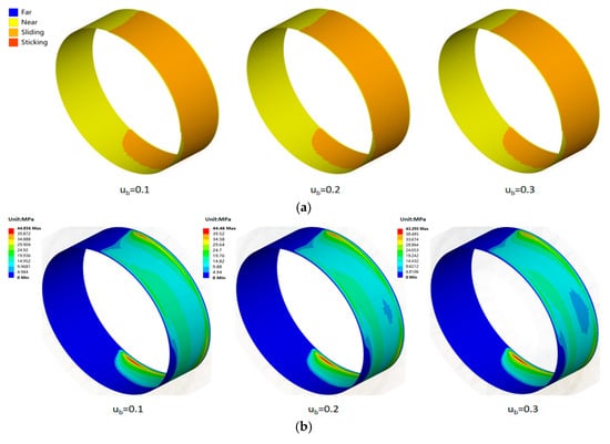
Figure 18.
Contact state and contact pressure on centering surface B at different friction coefficients: (a) contact state of centering surface B under different friction coefficients; (b) contact pressure on centering surface B under different friction coefficients.
The influence of friction coefficients on the stiffness of meshing tooth surfaces and pre-tightening surfaces is shown in Figure 17c,d. It can be observed that increasing the friction coefficient enhances the stiffness of the spline coupling to a certain extent. Under identical loading conditions, taking the meshing tooth surface at 20 kN as an example, an increase in the friction coefficient from 0.1 to 0.3 raises the stiffness from 2.573 × 10⁵ N/mm to 2.646 × 10⁵ N/mm, representing an approximate 2.76% increase. This occurs because the friction force direction on the tooth surface forms a very small angle with the load direction, partially reducing deformation caused by the load and thereby moderately enhancing stiffness.
In summary, whether modifying the friction coefficient of the centering surface or the meshing tooth surface, the impact on the stiffness of the spline coupling structure is limited. Therefore, in practical operation, it is sufficient to maintain the friction coefficient within a reasonable range.
4.2. Effect of Torque
During actual operation of an aero-engine, the torque transmitted by the spline coupling varies with changes in turbine output power. Therefore, different torque loads of 3 × 10⁵ N/mm, 5 × 10⁵ N/mm, and 8 × 10⁵ N/mm were applied, with the calculation results shown in Figure 19. The figure reveals that the variation patterns of stiffness under different torque loads are generally consistent, allowing classification into two distinct regimes: During the first regime, at loads below 8 kN, the stiffness remains nearly constant, with torque exhibiting negligible influence—a phenomenon consistent with the behavior discussed in Section 3.2.2. In the second regime, stiffness decreases rapidly with increasing load until eventually stabilizing. The stiffness at 8 × 10⁵ N/mm is significantly higher than at 3 × 10⁵ N/mm. For instance, at a load of 24 kN, the stiffness increases by approximately 5.39%. This occurs because higher torque enhances meshing contact effectiveness. The inner and outer tooth surfaces effectively connect the fan shaft and low-pressure turbine shaft, functioning similarly to centering surfaces that provide some support.
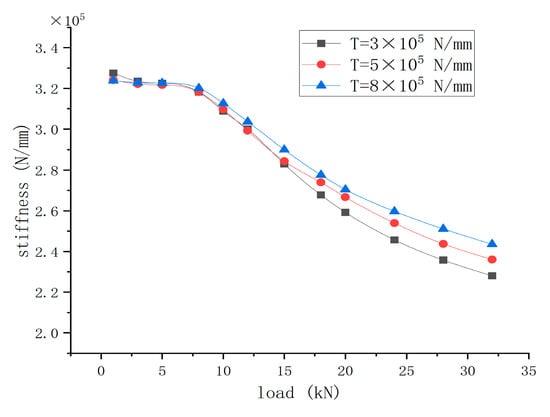
Figure 19.
Stiffness variation patterns under different torques.
Figure 20 illustrates the contact state and contact pressure distribution between centering surfaces A and B under a load of 18 kN at different torque levels. It can be observed that with increasing torque, the contact state of the centering surfaces changes, causing the contact area to become more concentrated. Consequently, the contact area of the centering surfaces gradually decreases with increasing torque. Under identical load conditions, as torque progressively increases, the frictional resistance against deformation decreases on centering surface A, while it increases on centering surface B. This leads to a smaller contact area on centering surface A compared to surface B. Furthermore, the contact pressure on centering surface A diminishes with increasing torque, and a similar decreasing trend is observed on centering surface B. Overall, the loss of stiffness is more pronounced at lower torque levels. As torque increases, the loss of stiffness in the spline coupling gradually diminishes. To a certain extent, this helps enhance the structural connection stability and increase the stiffness of the spline coupling.


Figure 20.
Contact state and contact pressure of the centering surface at different torques: (a) contact state of centering surface A; (b) contact state of centering surface B; (c) contact pressure of centering surface A; (d) contact pressure of centering surface B.
5. Conclusions
In this paper, the linear and angular stiffness of the spline coupling are first derived from theoretical models. Subsequently, a three-dimensional contact finite element model is established to analyze the contact state of the spline coupling under multiple contact surfaces. Based on this model, the study investigates the nonlinear stiffness of the spline coupling and the variation patterns of contact surface states from two perspectives: changes in contact surface conditions and contact surface sensitivity. Finally, key factors influencing the stiffness of the spline coupling are analyzed. The main conclusions of this study are summarized as follows:
- The fundamental characteristic causing nonlinear stiffness in spline couplings is the changing contact state of each contact surface under external loads. When all contact surfaces are bonded, the stiffness remains nearly linear and exhibits no significant nonlinear variation with increasing load. In contrast, when interfacial contact is considered, stiffness decreases nonlinearly with increasing load until it asymptotically approaches a near-constant value. As the centering surfaces transition from clearance to interference fit, their contact state gradually shifts from separation to sliding and sticking, accompanied by a continuous increase in contact pressure. So the continuous variation in contact area between centering surfaces is another significant cause of nonlinear stiffness changes.
- Considering the factors affecting stiffness variation across different contact surfaces under conditions of varying sensitivity to contact surfaces in spline couplings, it was established that stiffness exhibits the greatest sensitivity to alterations in the contact state of centering surface B. Analyzing the influence of both centering surfaces on stiffness under varying contact conditions reveals that reducing the clearance fit for both surfaces effectively enhances the spline couplings stiffness. Consequently, decreasing the clearance fit of centering surface B yields the most pronounced stiffness improvement. Furthermore, variations in the contact state of centering surface B exert a significant nonlinear effect on stiffness.
- Based on finite element modeling, the influence of varying friction coefficients and torque on the stiffness of spline couplings was analyzed. Under varying friction coefficients at the contact surfaces, both the contact state and contact pressure remained largely unaffected. The variation in the friction coefficient had a minor effect on stiffness and did not alter the fundamental trend of stiffness variation with respect to load. In contrast, under different torque conditions, the contact state at the surfaces changed significantly. At high loads, the effect of torque on stiffness became particularly significant. Torque demonstrated a more pronounced impact on the stiffness response of the spline coupling, making it a primary factor affecting its stiffness.
Building on these findings, we investigated the nonlinear stiffness characteristics of spline couplings in aeroengines, which are dominated by the evolution of multi-contact states. However, the operational behavior of spline couplings in actual engineering applications is more complex, indicating that there remains room for improvement in spline coupling research—an important topic for our future studies. Therefore, analyzing the nonlinear stiffness of spline couplings under various real-world operating conditions requires consideration of additional factors. Investigating the nonlinear stiffness variations in polygonal spline couplings under complex conditions holds significant importance for ensuring the stable operation of aeroengines.
Author Contributions
Conceptualization, C.H. and Y.F.; methodology, C.H. and Y.F.; software, C.H.; validation, C.H. and Y.F.; formal analysis, C.H.; investigation, C.H.; resources, Y.F.; data curation, C.H. and Y.F.; writing—original draft preparation, C.H. and Y.F.; writing—review and editing, C.H.; visualization, Y.F.; supervision, C.H. and Y.F.; project administration, Y.F.; funding acquisition, Y.F. All authors have read and agreed to the published version of the manuscript.
Funding
This study was supported by the Strategic Priority Research Program of the Chinese Academy of Sciences, Grant No. XDC0140000.
Data Availability Statement
The original contributions presented in this study are included in the article. Further inquiries can be directed to the corresponding author.
Conflicts of Interest
The authors declare no conflicts of interest.
References
- Zhao, G.; Zhao, X.; Qian, L.; Yuan, Y.; Ma, S.; Guo, M. A Review of Aviation Spline Research. Lubricants 2023, 11, 6. [Google Scholar] [CrossRef]
- Liu, S.; Wang, J.; Hong, J.; Zhang, D. Dynamics Design of the Aero-Engine Rotor Joint Structures Based on Experimental and Numerical Study. In Proceedings of the ASME Turbo Expo 2010: Power for Land, Sea, and Air, Glasgow, UK, 14–18 June 2010; Volume 6: Structures and Dynamics, Parts A and B, pp. 49–60. [Google Scholar]
- Wu, F.; Liang, Z.; Ma, Y.; Zhang, D. Bending Stiffness and Dynamic Characteristics of a Rotor With Spline Joints. In Proceedings of the ASME 2013 International Mechanical Engineering Congress and Exposition, San Diego, CA, USA, 15–21 November 2013; Volume 4A: Dynamics, Vibration and Control. [Google Scholar]
- Zhu, B.; Yang, C.; Liu, Y.; Zhang, D. Mechanical Modeling for the Spline Joint and the Influence Factors Investigation for Its Stiffness. Mach. Des. Manuf. 2019, S1, 86–90+94. [Google Scholar]
- Li, L.; Chen, G.; Yang, M. Simulation Analysis and Experimental Study of Stiffness Characteristics of Aeroengine Spline Couplings. China Mech. Eng. 2022, 33, 2249–2256. [Google Scholar]
- Zhao, G.; Su, J.; Han, Q.; Wang, M. Modelling and Simulation of Cylindrical Surface Contact Stiffness. J. Huazhong Univ. Sci. Technol. 2015, 43, 21–26. [Google Scholar]
- Hong, J.; Talbot, D.; Kahraman, A. A semi-analytical load distribution model for side-fit involute splines. Mech. Mach. Theory 2014, 76, 39–55. [Google Scholar] [CrossRef]
- Hong, J.; Talbot, D.; Kahraman, A. Load distribution analysis of clearance-fit spline joints using finite elements. Mech. Mach. Theory 2014, 74, 42–57. [Google Scholar] [CrossRef]
- Hong, J.; Talbot, D.; Kahraman, A. A generalized semi-analytical load distribution model for clearance-fit, major-fit, minor-fit, and mismatched splines. Proc. Inst. Mech. Eng. Part C J. Mech. Eng. Sci. 2016, 230, 1126–1138. [Google Scholar] [CrossRef]
- Curà, F.; Mura, A. Experimental procedure for the evaluation of tooth stiffness in spline coupling including angular misalignment. Mech. Syst. Signal Process. 2013, 40, 545–555. [Google Scholar] [CrossRef]
- Curà, F.; Mura, A. Experimental and theoretical investigation about reaction moments in misaligned splined couplings. Mech. Syst. Signal Process. 2014, 45, 504–512. [Google Scholar] [CrossRef]
- Curà, F.; Mura, A. Evaluation of the fretting wear damage on crowned splined couplings. Procedia Struct. Integr. Procedia 2017, 5, 1393–1400. [Google Scholar] [CrossRef]
- Curà, F.; Mura, A.; Gravina, M. Load distribution in spline coupling teeth with parallel offset misalignment. Proc. Inst. Mech. Eng. Part C J. Mech. Eng. Sci. 2013, 227, 2195–2205. [Google Scholar] [CrossRef]
- Curà, F.; Mura, A.; Adamo, F. Fatigue damage in spline couplings: Numerical simulations and experimental validation. Procedia Struct. Integr. Procedia 2017, 5, 1326–1333. [Google Scholar] [CrossRef]
- Hong, J.; Talbot, D.; Kahraman, A. A Stiffness Formulation for Spline Joints. J. Mech. Des. 2016, 138, 043301. [Google Scholar] [CrossRef]
- Marmol, R.; Smalley, A.; Tecza, J. Spline Coupling Induced Nonsynchronous Rotor Vibrations. J. Mech. Des. 1980, 102, 168–176. [Google Scholar] [CrossRef]
- Zhao, G.; Su, J.; Zhai, J.; Han, Q.; Shi, Y. Study on Nonlinear Meshing Stiffness of Spline. Mech. Mach. Sci. 2015, 21, 1315–1321. [Google Scholar]
- Yu, P.; Wang, C.; Liu, Y.; Chen, G. Analytical modeling of the lateral stiffness of a spline coupling considering teeth engagement and influence on rotor dynamics. Eur. J. Mech. A Solids 2022, 92, 104468. [Google Scholar] [CrossRef]
- Jiang, K.; Yu, P.; Yan, X.; Zheng, H.; Jiang, Z.; Tao, X. Numerical modelling and nonlinear mechanism analysis of the stiffness of flexible spline joint structures considering contact surface friction. China Mech. Eng. 2025, 12, 1–12. [Google Scholar]
- Huang, W.; Tian, H.; Ma, H.; Wang, P.; Yang, Y.; Han, Q. An improved method for calculating the lateral and angular stiffness of spline couplings considering parallel misalignment. Mech. Mach. Theory 2023, 189, 94–104. [Google Scholar] [CrossRef]
- Xie, C.; Shu, X. A new mesh stiffness model for modified spur gears with coupling tooth and body flexibility effects. Appl. Math. Model. 2021, 91, 1194–1210. [Google Scholar] [CrossRef]
- Wang, Q.; Xu, K.; Huai, T.; Ma, H.; Wang, K. A mesh stiffness method using slice coupling for spur gear pairs with misalignment and lead crown relief. Appl. Math. Model. 2021, 90, 845–861. [Google Scholar] [CrossRef]
- Wang, S.; Zhu, R. An improved mesh stiffness model of helical gear pair considering axial mesh force and friction force influenced by surface roughness under EHL condition. Appl. Math. Model. 2022, 102, 453–471. [Google Scholar] [CrossRef]
- Zhang, Q.; Li, W.; Liang, Z.; Hong, J. Study on the Stiffness Loss and its Affecting Factors of the Spline Joint Used in Rotor System. In Proceedings of the ASME Turbo Expo 2014: Turbine Technical Conference and Exposition, Düsseldorf, Germany, 16–20 June 2014; Volume 7A: Structures and Dynamics. [Google Scholar]
- Johnson, K. Contact Mechanics, 1st ed.; Cambridge University Press: Cambridge, UK, 1985. [Google Scholar]
- Harris, T.; Kotzalas, M. Rolling Bearing Analysis, 5th ed.; CRC Press: Boca Raton, FL, USA, 2007. [Google Scholar]
- Li, W. Experimental Study on the Dynamic Characteristics of Typical Spline Connection Structures of Aeroengines. Ph.D. Thesis, Beihang University, Beijing, China, 2013. [Google Scholar]
Disclaimer/Publisher’s Note: The statements, opinions and data contained in all publications are solely those of the individual author(s) and contributor(s) and not of MDPI and/or the editor(s). MDPI and/or the editor(s) disclaim responsibility for any injury to people or property resulting from any ideas, methods, instructions or products referred to in the content. |
© 2025 by the authors. Licensee MDPI, Basel, Switzerland. This article is an open access article distributed under the terms and conditions of the Creative Commons Attribution (CC BY) license.