Abstract
Prediction accuracy for complex flexible support systems is often limited by insufficiently characterized thermo-mechanical couplings and nonlinearities. To address this, we propose a multilevel hybrid parallel–serial model that integrates the thermo-viscous effects of a Squeeze Film Damper (SFD) via a coupled Reynolds–Walther equation, the structural flexibility of a squirrel-cage support using Finite Element analysis, and the load-dependent stiffness of a four-point contact ball bearing based on Hertzian theory. The resulting state-dependent system is solved using a force-controlled iterative numerical algorithm. For validation, a dedicated bidirectional excitation test rig was constructed to decouple and characterize the support’s dynamics via frequency-domain impedance identification. Experimental results indicate that equivalent damping is temperature-sensitive, decreasing by approximately 50% as the lubricant temperature rises from 30 °C to 100 °C. In contrast, the system exhibits pronounced stiffness hardening under increasing loads. Theoretical analysis attributes this nonlinearity primarily to the bearing’s Hertzian contact mechanics, which accounts for a stiffness increase of nearly 240%. This coupled model offers a distinct advancement over traditional linear approaches, providing a validated framework for the design and vibration control of aero-engine flexible supports.
1. Introduction
Modern aero-engines are evolving toward higher thrust-to-weight ratios, operational pressures, and rotational speeds. Consequently, lightweight flexible rotor systems have become highly susceptible to dynamic instabilities caused by residual unbalance, complex aerodynamic loads, or aggressive maneuvers [1,2,3]. In this context, the flexible support system—typically a hybrid assembly of rolling element bearings, squirrel-cage supports, and Squeeze Film Dampers (SFDs), as shown in Figure 1—serves not merely as a structural interface but as a critical functional module for managing system dynamics [4,5,6]. However, accurately predicting the behavior of these systems remains a challenge due to the complex, coupled nature of their components.
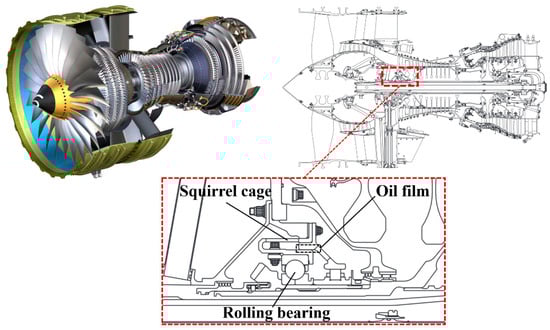
Figure 1.
Schematic diagram of the flexible support system illustrating the hybrid assembly of rolling bearings, squirrel-cage supports, and SFDs.
A primary limitation in current research is the lack of system-level modeling fidelity. Traditional approaches often rely on lumped-parameter models [7] that simplify component-level physical accuracy, effectively neglecting critical nonlinear couplings [8]. For instance, the load-dependent stiffness of a bearing alters its deformation, which governs the SFD eccentricity and the resulting nonlinear oil film force [9]. This force, in turn, acts back on the bearing, establishing a closed-loop dependency [10,11]. Luo et al. [12] contend that accurate rotor support modeling demands an integrated system-level perspective; isolated component analysis is insufficient. In practice, the thermal state of Squeeze Film Dampers (SFD) is frequently treated with excessive simplicity. Zhou et al. [13] provide experimental evidence that fluid shear generates significant heat, reducing viscosity and, by extension, damping capacity. The literature currently lacks a unified model capturing this thermo-viscous evolution alongside bearing contact nonlinearity. To capture this behavior, an integrated model must address specific modeling challenges for each component.
The dynamic behavior of SFDs is often oversimplified. Early analytical models based on isothermal assumptions [14,15,16,17,18] do not account for the significant heat generated by intense fluid shearing. Neglecting this thermo-viscous effect leads to a severe overestimation of damping [19]. While Computational Fluid Dynamics (CFD) methods [20] can capture these thermal effects, their computational cost is prohibitive for iterative system-level design. Thus, an analytical approach enhanced by temperature-viscosity coupling is required for efficiency. Second, regarding the squirrel-cage support, traditional beam-theory formulas [21] often yield significant errors by neglecting end-ring compliance and stress concentrations. Recent studies [22,23] have demonstrated that high-fidelity Finite Element Method (FEM) characterization is essential for accurate parameterization. Third, and perhaps most critically, rolling element bearings are frequently simplified as linear springs in macroscopic analyses [24,25,26,27]. This assumption ignores Hertzian contact mechanics [28,29], which govern that bearing stiffness increases with load. Neglecting this “stiffness hardening” renders predictions inaccurate, particularly under high-load conditions [30,31,32,33]. Recently, the phenomenon of prestress-induced hardening has also been extensively investigated in broader aerospace structural dynamics. Filippi et al. [34] analyzed wave propagation characteristics in complex prestressed structures using the Carrera Unified Formulation (CUF), revealing that geometric nonlinearities induce a hardening behavior that intensifies significantly with increasing preload, thereby altering modal frequencies. This finding corroborates the generic nature of the load-dependent stiffness hardening trend observed in bearing contact mechanics in this study from the perspective of generalized structural mechanics.
Experimental validation faces similar difficulties. Data from full-scale rotor rigs [35,36] inherently conflate the support’s dynamics with shaft flexibility and gyroscopic effects, making it difficult to isolate intrinsic support parameters. Existing identification methods [37,38] often have difficulty decoupling these convoluted dynamics.
To address these modeling and validation gaps, this paper introduces a synergistic research paradigm. We propose a multi-physics coupled model that integrates the SFD’s thermo-viscous behavior, the squirrel-cage’s FEM-derived flexibility, and the bearing’s Hertzian contact nonlinearity. The model is validated against a novel bidirectional orthogonal excitation test rig designed to isolate the support’s dynamics from rotational effects. This work details the model construction and experimental methodology, quantitatively analyzing the physical origins of the system’s thermo-nonlinear behaviors.
2. Coupled Multi-Physics Modeling
To accurately capture the nonlinear dynamic behavior of the flexible support system, we constructed a fidelity-matched model. This approach balances physical accuracy with computational tractability by modeling each component—the SFD, squirrel-cage support, and rolling element bearing—according to its specific governing physics and its role within the coupled state-dependent system.
2.1. Thermo-Hydrodynamic Model of the SFD
The geometric configuration and coordinate system of the Squeeze Film Damper (SFD) are illustrated in Figure 2. As the primary energy dissipation mechanism of the support system, the SFD’s behavior is governed by the pressure distribution within the oil film.
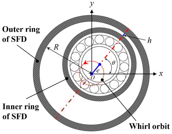
Figure 2.
Geometric model and coordinate system of the SFD. The red dashed circle and arrow indicate the whirl orbit and its direction, the blue solid line represents the eccentricity, and the red dashed straight line denotes the axis of symmetry.
While high-fidelity Computational Fluid Dynamics (CFD) methods can model this process, their high computational cost is unsuitable for the iterative system-level analysis required in this study. Consequently, we employ the short-bearing assumption (), a widely accepted approximation for aero-engine SFDs. The specific geometric parameters of the SFD in the test article are a journal diameter of = 201.76 mm and a land length of = 19 mm. This yields a length-to-diameter ratio that is approximately equal to 0.094, which falls well within the validity range () for the short-bearing approximation, as established in classical lubrication theory [39]. This simplifies the Reynolds equation, allowing for an analytical solution of the pressure field (Equation (1)). By integrating this pressure field, the oil film forces are obtained and, for small-amplitude harmonic motions, are linearized into equivalent stiffness () and damping () coefficients:
where denotes the instantaneous film thickness, the radial clearance, and the dimensionless eccentricity ratio. Geometric parameters , , and correspond to the axial coordinate, effective film length, and film radius, respectively, while represents the lubricant’s dynamic viscosity. The absence of journal rotation dictates that the pressure distribution is governed exclusively by the squeeze effect.
A critical aspect of this model is the bidirectional thermo-mechanical coupling. The energy dissipated by fluid shearing generates significant heat, which governs the lubricant’s dynamic viscosity and, consequently, the damping coefficient itself. To accurately capture this dependency, the model integrates the Walther viscosity-temperature equation (Equation (4)), which establishes the functional relationship between the lubricant’s absolute temperature and its kinematic viscosity :
where and are material-specific constants; they are specific to the experimental lubricant (VG32). They were derived by fitting standard kinematic viscosity data across the temperature range, strictly adhering to ASTM D341 [40]. The dynamic viscosity is updated via . This equation closes the loop between the thermal state and the system’s dynamic characteristics.
2.2. Finite Element Modeling of the Squirrel-Cage Support
The squirrel-cage support establishes the baseline structural stiffness () for the entire support assembly. Its specific structure and geometric parameters are depicted in Figure 3. While classical analytical models based on beam theory (Equation (5)) are frequently used for preliminary design, they fundamentally neglect the compliance of the end rings and local stress concentrations:
where is the correction factor, is the number of flexible beams, is the elastic modulus, , and are the effective length, width, and thickness of the beams.
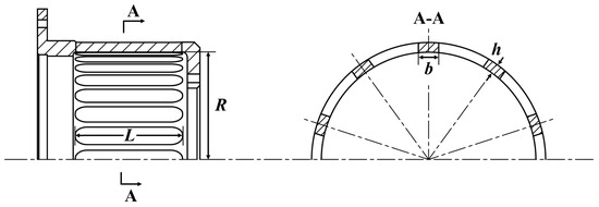
Figure 3.
Structure and geometric parameters of the squirrel-cage.
For the component under study, this simplified analytical approach predicted a stiffness of N/m. To obtain a parameter with higher fidelity, we developed a three-dimensional Finite Element Method (FEM) model using ANSYS Workbench 2024 R1, as shown in Figure 4. The static structural analysis yielded a corrected equivalent radial stiffness of N/m. The significant 44% discrepancy between the analytical and numerical results highlights the inadequacy of simple beam theory for this complex geometry. Consequently, the FEM-derived stiffness value is adopted as the constant linear stiffness contribution in the final coupled system model.
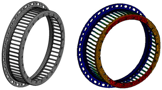
Figure 4.
High-fidelity finite element model of the squirrel-cage support (left) and the corresponding static analysis results for radial stiffness (right). The color gradient from blue to red indicates the increasing magnitude of total deformation.
2.3. Nonlinear Bearing Model
System-level rotordynamic analyses frequently simplify rolling element bearings as linear springs. However, this assumption does not fully capture the “stiffness hardening” effect, which is the dominant source of nonlinearity in such systems. To accurately predict dynamic response, particularly under high loads, we employ a nonlinear analytical model based on Hertzian contact mechanics. The specific geometric configuration of the four-point contact ball bearing used in this study is illustrated in Figure 5.
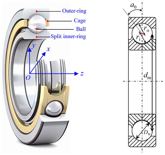
Figure 5.
Schematic diagram of the structure and geometric parameters of the four-point contact ball bearing.
According to Hertzian theory, the normal contact load on the -th ball is governed by a nonlinear power-law relationship with its contact deformation :
When the bearing is subjected to external loading, the inner ring undergoes a generic displacement characterized by radial () and axial () components. The resulting change in distance between the ball center and the raceway curvature center leads to the contact deformation . This kinematic relationship is expressed as:
where the effective contact deformation depends on the initial contact angle and the geometric coefficients (curvature sum function) and (Hertzian deflection coefficient), which are determined by the raceway groove curvature radii:
In the proposed formulation, the subscripts and denote the inner and outer raceways, respectively. The parameters and represent the raceway groove curvature coefficients (), which determine the conformity of the contact. is the ball diameter, is the bearing pitch diameter, and represents the total number of rolling elements.
The total radial restoring force is obtained by summing the projected radial components of the reaction forces from all balls. Consequently, the bearing’s transient radial stiffness is defined as the derivative of this total force with respect to the radial displacement :
Crucially, Equation (13) demonstrates that is a function of . This mathematically confirms that the bearing stiffness is not constant but varies instantaneously with the vibration amplitude, establishing the system’s fundamental nonlinear characteristic. This study targets planar radial dynamics; therefore, we utilize a Hertzian contact model that isolates nonlinear stiffness characteristics under radial excitation. This formulation assumes a static axial preload, omitting the explicit coupling of dynamic axial loads. In complex operating conditions involving substantial axial forces, this factor cannot be ignored.
2.4. Integrated System Model and Solution Framework
The physical assembly of the flexible support is represented mathematically by a hybrid stiffness network topology, as illustrated in Figure 6. In this configuration, the squirrel-cage support () and the SFD oil film () operate in parallel, sharing a common radial displacement. Their combined equivalent stiffness is:
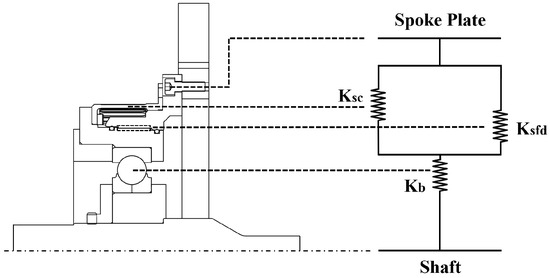
Figure 6.
Equivalent stiffness model illustrating the hybrid parallel-serial topology of the flexible support system.
This parallel subsystem is connected in series with the four-point contact ball bearing (). In a series connection, the force is transmitted equally through the components, while the total displacement is the sum of the individual contributions. Consequently, the total equivalent stiffness of the system () is given by:
A fundamental challenge in solving this system is its inherent state-dependence: the stiffness matrix depends on the unknown displacement vector, precluding a direct analytical solution. Specifically, is a function of the journal eccentricity ratio , while depends on the bearing’s radial deformation . To resolve this nonlinearity, we developed a force-controlled iterative numerical algorithm, the flowchart of which is presented in Figure 7.
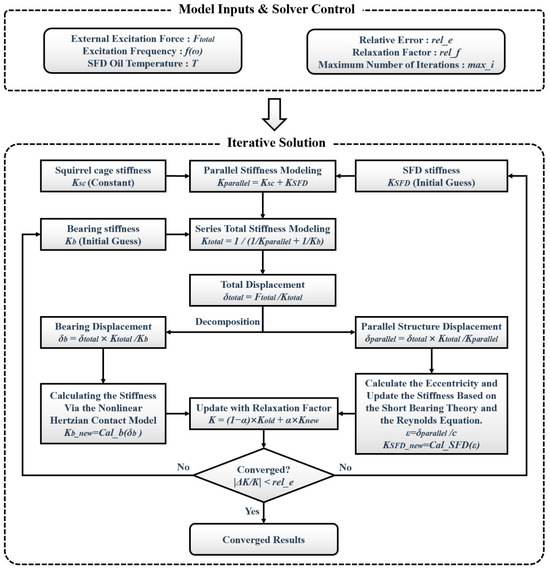
Figure 7.
Flowchart of the iterative solution algorithm for the nonlinear stiffness of the coupled system.
The solution procedure operates as follows: First, for a given set of inputs (excitation force , frequency, and oil temperature), initial estimates for the nonlinear stiffnesses ( and ) are assumed. The total system stiffness is then calculated to determine the global displacement . Crucially, this total displacement is then partitioned among the components based on the serial topology:
These partitioned displacements serve as the state variables to update the nonlinear stiffnesses for the next iteration: is input into the Hertzian contact model (Section 2.3) to update , while determines the eccentricity for the thermo-hydrodynamic model (Section 2.1) to update . To ensure numerical stability, a relaxation factor is applied to the stiffness updates (Equation (17)). The iteration continues until the relative stiffness change converges to within a predefined tolerance (e.g., 1%).
3. Experimental Methodology
To validate the coupled multi-physics model and address the “validation gap” identified in the Introduction, we designed and constructed a dedicated experimental facility. The core innovation of this rig is its ability to perform direct dynamic characterization of the support assembly. Unlike full-rotor test rigs, this setup isolates the support’s intrinsic properties from confounding rotational dynamics, such as shaft flexibility and gyroscopic effects, providing a direct and reliable benchmark.
3.1. Bidirectional Excitation Test Rig
The overall layout of the test system is illustrated in Figure 8. It comprises four integrated modules designed to simulate realistic operating conditions while ensuring precise measurement control:
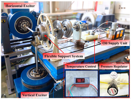
Figure 8.
Overall layout and key components of the bidirectional excitation test system.
- Support Structure Platform: The test article—a complete flexible support assembly identical to the simulation model—is mounted on a high-stiffness, seismically isolated base to ensure measurement integrity. A rigid, non-rotating shaft is installed through the bearing to serve as the mechanical interface for load application.
- Bidirectional Excitation Module: To simulate complex planar dynamic loads, two orthogonally mounted electrodynamic shakers (EDM-1000, 10 kN, ECON Technologies Co., Ltd., Hangzhou, China) apply forces in the X and Y directions. This configuration is critical for characterizing the system’s anisotropic properties.
- Lubricant Temperature Control Module: Given the SFD’s thermo-viscous sensitivity, a closed-loop conditioning system is employed. A PID-controlled heater and pump unit circulate oil through the damper, maintaining the inlet temperature between 30 °C and 100 °C with a precision of ±0.1 °C.
- Measurement and Data Acquisition: The sensor arrangement is detailed in Figure 9. Two piezoelectric force transducers (JLBM-500, ±5 kN, Bengbu Sensor System Engineering Co., Ltd., Bengbu, China) are installed between the shakers and the shaft to measure input excitation. Simultaneously, the shaft’s planar displacement response is captured non-intrusively by two orthogonal eddy current proximity probes (RP6605XL, ±5 mm, Shanghai Zhongxi Industrial Co., Ltd., Shanghai, China). All four signal channels are synchronized via a data acquisition system (cDAQ-9185, National Instruments, Austin, TX, USA) at a sampling rate of 5120 Hz, ensuring the capture of both amplitude and phase information essential for parameter identification. Measurement fidelity mandated a strict calibration protocol prior to dynamic testing. We subjected the piezoelectric force transducers (JLBM-500) to static linearity verification using standard weights. In situ calibration of the eddy current proximity probes (RP6605XL) utilized a precision micrometer stage. Mapping the gap-voltage curve indicated that sensitivity remains constant across the operational band. Consequently, linearity error stays below 1%.
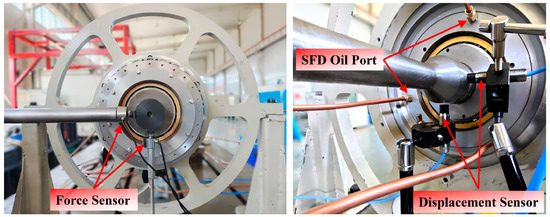 Figure 9. Installation details of the force and displacement sensors.
3.2. Experimental Protocol
The experimental campaign was designed to systematically characterize the support system’s dynamic response under varying thermal and loading conditions. The detailed test matrix is summarized in Table 1. To verify experimental reproducibility, each test condition listed in Table 1 was performed five times independently. Two primary testing procedures were executed:

Table 1.
Experimental test matrix and parameter settings.
- Swept-Frequency Test: To identify the system’s natural frequencies and baseline dynamic signature, a linear frequency sweep was conducted from 20 Hz to 320 Hz. During this test, the excitation force amplitude was maintained at a constant 1200 N.
- Fixed-Frequency, Variable-Force Test: To investigate the load-dependent nonlinearities, tests were performed at a fixed representative frequency (40 Hz, near the identified first natural frequency). At this frequency, the excitation force amplitude was incrementally stepped through three levels: 1200 N, 2200 N, and 3200 N.
3.3. Parameter Identification Methodology
To extract the equivalent dynamic parameters—specifically stiffness () and damping ()—of the support system, we employed a frequency-domain dynamic stiffness identification method. Unlike time-domain fitting, this approach effectively decouples the inertial, damping, and elastic contributions to the system’s response based on their phase characteristics, providing a robust framework for parameter estimation.
The bidirectional exciters were controlled with a 90° phase difference to generate a centered circular orbit, mimicking the realistic whirl motion of the rotor. Given the axisymmetric nature of the support structure, dynamic isotropy is assumed where the radial properties are uniform. Consequently, the equivalent dynamic stiffness and damping can be accurately identified using the response data projected onto a single axis.
By modeling the support system as a linearized single-degree-of-freedom oscillator (Equation (18)), the equation of motion is transformed into the frequency domain (Equation (19)). We define the dynamic stiffness, denoted as , as the frequency-dependent ratio of the excitation force phasor to the displacement response phasor (Equation (20)):
In the experimental procedure, the time-domain signals of the applied force and the resulting displacement are converted to the frequency domain via a Fast Fourier Transform (FFT). The dynamic stiffness is then computed at each frequency point. By separating the real and imaginary components of , the system parameters are directly identified from the measured data:
Consequently, the frequency-dependent equivalent stiffness and damping coefficients are identified as:
This frequency-domain dynamic stiffness identification method is particularly advantageous for characterizing properties near resonance, where the large displacement amplitudes ensure a high signal-to-noise ratio and accurate parameter identification.
The raw experimental data were digitized at a sampling rate of 5120 Hz and processed via a discrete Fourier transform approach to accurately extract amplitude and phase information. To minimize spectral leakage caused by non-integer period sampling, a Hanning window was applied to the time-domain signals prior to the FFT operation. Subsequently, the spectral components at the excitation frequency were identified by searching for the peak amplitude within a narrow bandwidth (1 Hz) around the target frequency, with the complex values corrected by the window’s energy coefficient. Furthermore, the inherent phase lag between the force and displacement sensors was pre-calibrated in the frequency domain, and only data segments from the stable operation phase were selected to ensure a high signal-to-noise ratio and the reliability of the point-by-point impedance identification.
4. Model Validation and Dynamic Characteristic Analysis
4.1. Baseline Dynamic Characterization
The experimental validation commences with establishing the fundamental dynamic baseline of the support system. A linear frequency sweep (20–320 Hz) was performed to map the system’s global response. The resulting amplitude-frequency-time waterfall plot, presented in Figure 10, reveals the system’s dynamic signature and clearly identifies the first natural frequency at 39.25 Hz. This critical finding determined the selection of 40 Hz as the anchor frequency for all subsequent fixed-frequency tests aimed at probing the system’s nonlinear and thermo-mechanical behaviors. Furthermore, Figure 11 displays typical high-fidelity time-domain signals for excitation force and displacement recorded at this condition. These signals serve as the raw data input for the impedance-based parameter identification detailed in Section 3.3.
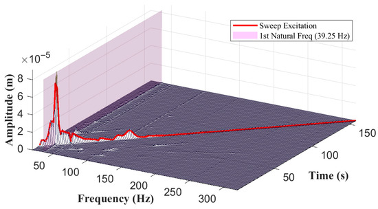
Figure 10.
System dynamic response from the swept-frequency test, identifying the first natural frequency at 39.25 Hz.
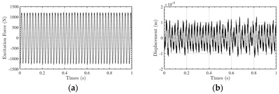
Figure 11.
Typical time-domain signals recorded at 40 Hz and 1200 N. (a) Excitation force signal. (b) Displacement signal.
4.2. Effect of Temperature: Thermo-Mechanical Validation
This section validates the model’s ability to capture the critical thermo-mechanical coupling effects. The system’s equivalent dynamic parameters were identified across an oil supply temperature range of 30 °C to 100 °C.
First, the system’s equivalent stiffness demonstrated distinct thermal stability, as illustrated in Figure 12. The experimental data (yellow markers) indicate only a marginal reduction in stiffness across the entire 70 °C range. The model predictions (blue line) are in good agreement with this trend. Physically, this result confirms that the total system stiffness is predominantly governed by the structural components (the squirrel-cage and bearing), whose material properties remain stable in this temperature range, thereby overshadowing the thermally sensitive stiffness contribution of the SFD oil film.
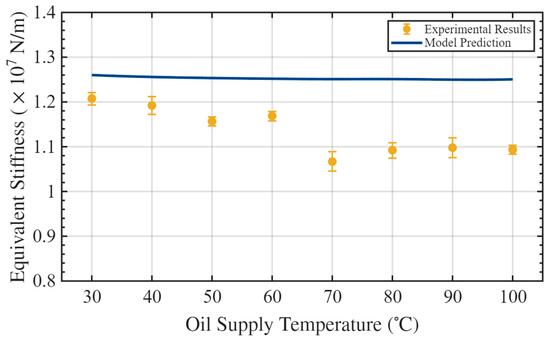
Figure 12.
Comparison of model-predicted and experimentally identified equivalent stiffness as a function of oil supply temperature (at 40 Hz, 1200 N).
Conversely, the equivalent damping exhibited a significant dependence on temperature, as shown in Figure 13. Experimentally, the identified damping coefficient decreased by over 50%, dropping from a peak of N·s/m at 30 °C to N·s/m at 100 °C. This decay is a direct manifestation of the exponential reduction in lubricant viscosity due to heating, which severely reduces the SFD’s energy dissipation capacity. The theoretical model, incorporating the Walther viscosity-temperature equation, successfully captures this fundamental trend. While a consistent quantitative offset is observed—where the model under-predicts the damping magnitude—this is an expected characteristic of the short-bearing assumption (), which inherently overestimates side leakage effects. The analytical short-bearing model (Equation (3)) inherently assumes open ends with ambient pressure, implying unrestricted axial flow. However, the experimental test rig incorporates O-ring seals at both ends of the damper to ensure oil supply pressure. These physical seals effectively restrict the side leakage, thereby maintaining higher fluid film pressures and generating larger hydrodynamic damping forces than theoretically predicted by the open-end assumption.
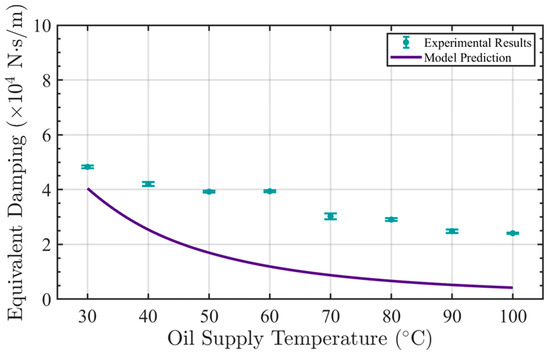
Figure 13.
Comparison of model-predicted and experimentally identified equivalent damping as a function of oil supply temperature (at 40 Hz, 1200 N).
4.3. Effect of Load: Nonlinearity and Stiffness Hardening
The second phase of validation investigated the system’s response to varying excitation loads, specifically targeting the nonlinear “stiffness hardening” phenomenon. As presented in Figure 14, the experimental results (yellow markers) demonstrate a clear trend: the equivalent stiffness progressively increases with the applied dynamic load. This behavior stands in distinct contrast to the traditional linear model (dashed gray line), which assumes a constant stiffness, thereby failing to predict the system’s actual response under higher loads.
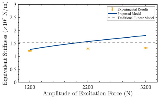
Figure 14.
Comparison of model-predicted and experimentally identified equivalent stiffness as a function of excitation force amplitude (at 40 Hz, 30 °C).
The proposed coupled model (blue line), driven by the nonlinear Hertzian contact mechanics detailed in Section 2.3, captures this hardening effect effectively, particularly at the 1200 N and 2200 N force levels. At the maximum tested load of 3200 N, the model predicts a slightly steeper stiffness gradient than observed experimentally. This minor deviation likely indicates the onset of secondary physical effects not included in the current formulation, such as micro-slip at the contact interfaces or localized plasticity, which would tend to limit the extent of stiffness hardening.
Regarding energy dissipation, the system damping also exhibited a load-dependent nonlinearity, as illustrated in Figure 15. Both experimental identification and model predictions show a modest increase in equivalent damping as the excitation force rises. Physically, this is attributed to the larger journal orbits induced within the SFD at higher load levels. These expanded orbits result in higher fluid shear velocities, thereby enhancing the hydrodynamic energy dissipation. The model’s ability to reproduce these coupled nonlinear trends in both stiffness and damping further corroborates its validity.
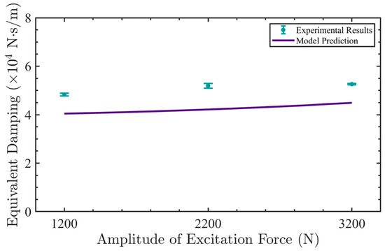
Figure 15.
Comparison of model-predicted and experimentally identified equivalent damping as a function of excitation force amplitude (at 40 Hz, 30 °C).
4.4. Analysis of Internal Coupling Mechanisms
Following the validation of the model’s macroscopic accuracy, the model is employed to investigate internal coupling mechanisms. This theoretical analysis provides quantitative insights into component-level interactions that are challenging to isolate through experimental measurements alone.
To elucidate the origin of the “stiffness hardening” observed in Section 4.3, the stiffness contributions of the bearing and the SFD were analyzed separately. As shown in Figure 16, increasing the excitation force from 1200 N to 3200 N results in a substantial increase in bearing stiffness () of nearly 240%, whereas the SFD stiffness () shows only a minor increase of 15%. This quantitative comparison confirms that the system’s macroscopic nonlinearity is primarily governed by the Hertzian contact mechanics of the bearing, rendering the SFD’s nonlinear contribution secondary in this high-load regime.
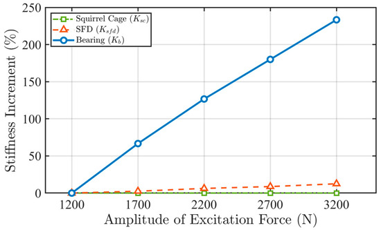
Figure 16.
Model-predicted stiffness increment (%) of individual components, identifying the bearing () as the primary source of system nonlinearity.
Regarding the phenomenon identified in Section 4.2, where the total stiffness remained thermally stable despite the high thermal sensitivity of the damping, the stiffness decomposition of the parallel subsystem offers a physical explanation. Figure 17 illustrates that as the oil temperature rises, the SFD stiffness () decreases by nearly 90% due to viscosity reduction. However, the total parallel stiffness () remains essentially constant. This stability is attributed to the structural stiffness of the squirrel-cage support (), which is numerically dominant in the parallel configuration and effectively overshadows the thermal variations in the oil film. Consequently, the squirrel-cage support, rather than the oil film, governs the static stiffness of the parallel assembly.
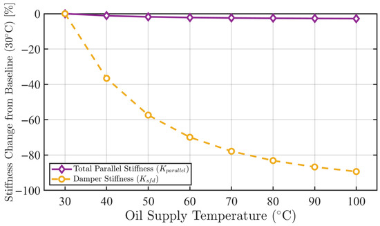
Figure 17.
Model-predicted stiffness change (%) of parallel components, illustrating the stiffness dominance of the squirrel-cage support over the thermally sensitive SFD.
This internal stiffness dominance directly determines the kinematic behavior of the system, specifically the displacement partitioning shown in Figure 18. At lower loads (1200 N), the bearing accounts for 23.0% of the total displacement. As the load increases, the stiffness hardening of the bearing shifts the load distribution, causing the parallel subsystem to accommodate a larger proportion of the total motion (28.9% at 3200 N). These results highlight the complex interaction between components, where the nonlinear hardening of one element alters the load path and obscures the thermal sensitivity of another, underscoring the necessity of an integrated modeling approach.
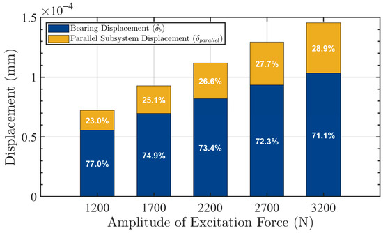
Figure 18.
Model-predicted displacement distribution between the bearing () and the parallel subsystem () under increasing excitation force.
5. Conclusions
This study addresses the critical challenge of predictive inaccuracy in aero-engine flexible support systems, which stems from uncharacterized nonlinearities and thermo-mechanical couplings. By bridging the gap between component-level physics and system-level dynamics, this research establishes a synergistic theoretical and experimental framework. The primary conclusions and contributions are summarized as follows:
- Establishment of a High-Fidelity Coupled Model: A multilevel hybrid parallel–serial model was developed to resolve the fidelity gap in traditional approaches. This integrated framework synthesizes the thermo-viscous behavior of the SFD (via the coupled Reynolds–Walther equation), the high-fidelity structural flexibility of the squirrel-cage support (via FEM), and the load-dependent Hertzian contact mechanics of the bearing. A robust iterative algorithm was implemented to solve the resulting state-dependent system, enabling accurate prediction of bidirectional coupling effects.
- Experimental Validation via Decoupled Characterization: The model’s predictive capability was rigorously validated against a novel bidirectional excitation test rig designed to isolate the support’s intrinsic dynamics. The results quantify two distinct macroscopic behaviors: system damping is dominated by thermo-viscous effects, decreasing by over 50% as the lubricant temperature rises from 30 °C to 100 °C; conversely, system stiffness is governed by load-dependent nonlinearity, exhibiting significant “stiffness hardening” while remaining essentially insensitive to thermal variations. Despite the validation of dynamic trends, a quantitative underestimation of the damping coefficient was observed. This deviation is attributed to the short-bearing assumption, which tends to overestimate side leakage by neglecting boundary fluid inertia. Future work will aim to correct this by incorporating finite-length bearing factors or end-leakage correction models.
- Elucidation of Internal Coupling Mechanisms: Theoretical analysis quantitatively revealed the physical origins of the observed macroscopic responses. The “stiffness hardening” phenomenon is clearly attributed to the bearing’s Hertzian contact mechanics, which showed a stiffness increase of nearly 240% under load, rendering the SFD’s nonlinear contribution secondary. Furthermore, the apparent thermal insensitivity of the total stiffness is explained by the structural dominance of the squirrel-cage support, which effectively masks the high thermal sensitivity of the SFD oil film.
Regarding engineering applications, we explicitly recommend the proposed multi-level coupled model as a verification tool during the preliminary design and parameter matching phases of aero-engine support systems. Prior to conducting time-consuming, detailed finite element analyses and costly full-scale whole-engine tests, designers can utilize this model to rapidly iterate and evaluate the effects of temperature and load variations on the system’s nonlinear dynamic characteristics. This capability allows for the optimization of initial design parameters, thereby significantly reducing trial-and-error costs. In summary, this work provides a validated, high-fidelity methodology that overcomes the limitations of linear or decoupled assumptions. It offers a robust theoretical foundation and a precise experimental benchmark essential for the advanced design and vibration control of next-generation aero-engine support systems.
Author Contributions
Conceptualization, X.M. and Q.H.; methodology, X.M.; software, X.M.; validation, X.M., Q.Z. and Q.H.; formal analysis, X.M.; investigation, X.M.; resources, Q.H.; data curation, X.M.; writing—original draft preparation, X.M.; writing—review and editing, X.M., Q.H., Q.Z. and J.L.; visualization, X.M.; supervision, Q.H.; project administration, Q.H.; funding acquisition, Q.H. All authors have read and agreed to the published version of the manuscript.
Funding
This research was funded by the Guangdong Basic and Applied Basic Research Foundation (grant No. 2024A1515110107), Basic Research Business Fee of the Central University of Education (grant No. N25XQD042), National Natural Science Foundation of China (grant No. 92360305), and National Natural Science Foundation of China (Grant No. 12502056).
Institutional Review Board Statement
Not applicable.
Informed Consent Statement
Not applicable.
Data Availability Statement
The original contributions presented in this study are included in the article. Further inquiries can be directed to the corresponding author.
Conflicts of Interest
The authors declare no conflicts of interest.
References
- Zhang, F.; Li, X.; Han, Q.; Guo, S.; Han, S.; Zhang, H. Research on Dynamic Balance Optimization Method of Flexible Rotor Based on GWO. Meas. Sci. Technol. 2024, 35, 106108. [Google Scholar] [CrossRef]
- Zhao, Y.; Liu, T.; Zhu, Y.-P.; Liu, Z.; Han, Q.; Ma, H. Lifelong Monitoring of Bearing-Rotor Systems Over Whole Life Cycle: An Emerging Paradigm. IEEE Trans. Ind. Inf. 2025, 21, 1319–1328. [Google Scholar] [CrossRef]
- Yang, T.; Wu, D.; Qiu, S.; Guo, S.; Li, X.; Han, Q. The STAP-Net: A New Health Perception and Prediction Framework for Bearing-Rotor Systems under Special Working Conditions. Reliab. Eng. Syst. Saf. 2025, 254, 110633. [Google Scholar] [CrossRef]
- San Andrés, L.; Den, S.; Jeung, S.-H. Transient Response of a Short-Length (L/D = 0.2) Open-Ends Elastically Supported Squeeze Film Damper: Centered and Largely Off-Centered Whirl Motions. J. Eng. Gas Turbines Power 2016, 138, 122503. [Google Scholar] [CrossRef]
- Vance, J.M.; Zeidan, F.Y.; Murphy, B.G. Machinery Vibration and Rotordynamics; John Wiley & Sons: Hoboken, NJ, USA, 2010. [Google Scholar]
- Ri, K.; Jang, J.; Yun, C.; Pak, C.; Kim, K. Analysis of Subharmonic and Quasi-Periodic Vibrations of a Jeffcott Rotor Supported on a Squeeze-Film Damper by the IHB Method. AIP Adv. 2022, 12, 055328. [Google Scholar] [CrossRef]
- Andréas, L.S.; De Santiago, O. Identification of Journal Bearing Force Coefficients under High Dynamic Loading Centered Static Operation. Tribol. Trans. 2005, 48, 9–17. [Google Scholar] [CrossRef]
- Adiletta, G.; Della Pietra, L. The Squeeze Film Damper over Four Decades of Investigations. Part II: Rotordynamic Analyses with Rigid and Flexible Rotors. Shock. Vib. Dig. 2002, 34, 97–126. [Google Scholar]
- Inayat-Hussain, J.I.; Kanki, H.; Mureithi, N.W. Chaos in the Unbalance Response of a Rigid Rotor in Cavitated Squeeze-Film Dampers without Centering Springs. Chaos Solitons Fractals 2002, 13, 929–945. [Google Scholar] [CrossRef]
- Yang, X.; Jiang, B.; Li, Y.; Zhao, Q.; Deng, S.; Zhang, W.; Cui, Y. Dynamic Characteristics of Elastic Ring Squeeze Film Damper Coupled High-Speed Ball Bearings. J. Sound Vib. 2022, 537, 117186. [Google Scholar] [CrossRef]
- Yang, X.; Jiang, B.; Li, Y.; Zhao, Q.; Deng, S. Dynamic Characteristics of Elastic Ring Squeeze Film Damper Oscillated by Bearing Contact Force. J. Vib. Eng. Technol. 2024, 12, 433–455. [Google Scholar] [CrossRef]
- Luo, Z.; Wang, J.; Han, Q.; Wang, D. Review on Dynamics of the Combined Support-Rotor System. J. Mech. Eng. 2021, 57, 44. [Google Scholar] [CrossRef]
- Zhou, H.; Cao, G.; Chen, X.; Zhang, Y.; Cang, Y. A Study on the Thermal Properties of Oil-Film Viscosity in Squeeze Film Dampers. Lubricants 2023, 11, 163. [Google Scholar] [CrossRef]
- Andres, S. Analysis of Short Squeeze Film Dampers with a Central Groove. ASME Trans. J. Tribol. 1992, 114, 659–664. [Google Scholar] [CrossRef]
- Gehannin, J.; Arghir, M.; Bonneau, O. A Volume of Fluid Method for Air Ingestion in Squeeze Film Dampers. Tribol. Trans. 2016, 59, 208–218. [Google Scholar] [CrossRef]
- Zhang, W.; Han, B.; Zhang, K.; Ding, Q. Dynamic Analysis of a Rotor System Supported on Squeeze Film Damper with Air Entrainment. Int. J. Bifurc. Chaos 2017, 27, 1750212. [Google Scholar] [CrossRef]
- Shaik, K.; Dutta, B.K. Tuning Criteria of Nonlinear Flexible Rotor Mounted on Squeeze Film Damper Using Analytical Ap-proach. J. Vib. Eng. Technol. 2021, 9, 325–339. [Google Scholar] [CrossRef]
- Karimulla, S.; Dutta, B.K.; Gouthaman, G. Experimental and Analytical Investigation of Short Squeeze-Film Damper (SFD) Under Circular-Centered Orbit (CCO) Motion. J. Vib. Eng. Technol. 2020, 8, 215–224. [Google Scholar] [CrossRef]
- Gupta, R.K.; Singh, R.C. Dynamic Experimental Investigation and Optimization of Flexible Rotor Vibration Control Using Squeeze Film Damper. J. Vib. Eng. Technol. 2025, 13, 79. [Google Scholar] [CrossRef]
- Perreault, M.; Hamzehlouia, S.; Behdinan, K. Application of Computational Fluid Dynamics for Thermohydrodynamic Analysis of High-Speed Squeeze-Film Dampers. Trans. Can. Soc. Mech. Eng. 2019, 43, 306–321. [Google Scholar] [CrossRef]
- Chatzisavvas, I.; Arsenyev, I.; Grahnert, R. Design and Optimization of Squirrel Cage Geometries in Aircraft Engines toward Robust Whole Engine Dynamics. Appl. Comput. Mech. 2023, 17, 2. [Google Scholar] [CrossRef]
- Zhang, W.; Han, B.; Li, X.; Sun, J.; Ding, Q. Multiple-Objective Design Optimization of Squirrel Cage for Squeeze Film Damper by Using Cell Mapping Method and Experimental Validation. Mech. Mach. Theory 2019, 132, 66–79. [Google Scholar] [CrossRef]
- Han, Q.; Chen, Y.; Zhang, H.; Jiang, L.; Li, X. Vibrations of Rigid Rotor Systems with Misalignment on Squirrel Cage Supports. J. Vibroeng. 2016, 18, 4329–4339. [Google Scholar] [CrossRef]
- Zhang, F.; Li, X.; Han, Q.; Zhao, Y.; Li, H.; Lin, J. Study on the Influence of Combined Unbalanced Phase Difference on Rotor Vibration Response and High-Speed Dynamic Balancing. J. Vib. Control. 2025, 10775463251342286. [Google Scholar] [CrossRef]
- Gupta, P.K. Dynamics of Rolling-Element Bearings—Part III: Ball Bearing Analysis. J. Lubr. Technol. 1979, 101, 312–318. [Google Scholar] [CrossRef]
- Harris, T.A.; Kotzalas, M.N. Advanced Concepts of Bearing Technology: Rolling Bearing Analysis; CRC Press: Boca Raton, FL, USA, 2006. [Google Scholar]
- Ghafari, S.H.; Abdel-Rahman, E.M.; Golnaraghi, F.; Ismail, F. Vibrations of Balanced Fault-Free Ball Bearings. J. Sound Vib. 2010, 329, 1332–1347. [Google Scholar] [CrossRef]
- Li, Z.; Wang, C.; Hu, X.; Xu, E.; Yang, L. Thermal-Mechanical Coupling Performance and Its Influence on Thermal Stiffness of Cylindrical Roller Bearings. J. Aerosp. Eng. 2024, 37, 04024031. [Google Scholar] [CrossRef]
- Fang, B.; Wan, S.; Zhang, J.; Hong, J. Research on the Influence of Clearance Variation on the Stiffness Fluctuation of Ball Bearing under Different Operating Conditions. J. Mech. Des. 2021, 143, 023403. [Google Scholar] [CrossRef]
- Zhao, Y.; Liu, Z.; Yang, Z.; Han, Q.; Ma, H. Machinery Fault Diagnosis-Oriented Regularization for Nonlinear System Identi-fication: Framework and Applications. Appl. Acoust. 2025, 231, 110537. [Google Scholar]
- Lacroix, S.; Nélias, D.; Leblanc, A. Experimental Study of Four-Point Contact Ball Bearing with Deformable Rings. Tribol. Trans. 2015, 58, 963–970. [Google Scholar] [CrossRef]
- Xiao, L.; Yan, F.; Chen, T.; Zhang, S.; Jiang, S. Study on Nonlinear Dynamics of Rigid-Flexible Coupling Multi-Link Mechanism Considering Various Kinds of Clearances. Nonlinear Dyn. 2023, 111, 3279–3306. [Google Scholar] [CrossRef]
- Yang, T.; Wang, S.; Jiang, S.; Ma, H.; Jiang, L.; Han, Q.; Wang, X.; Li, X. MSPI-Net Framework: A Novel Optimizer-Powered Multi-Source Physical Information Fusion Approach for Intelligent Diagnosis and Interpretability of Bearings. Expert Syst. Appl. 2025, 296, 129279. [Google Scholar]
- Filippi, M.; Magliacano, D.; Petrolo, M.; Carrera, E. Wave Propagation in Pre-Stressed Structures with Geometric Non-Linearities Through Carrera Unified Formulation. AIAA J. 2025, 63, 292–308. [Google Scholar] [CrossRef]
- Andrés, L.S.; Rodríguez, B. On the Experimental Dynamic Force Performance of a Squeeze Film Damper Supplied through a Check Valve and Sealed with O-Rings. J. Eng. Gas Turbines Power 2021, 143, 111011. [Google Scholar] [CrossRef]
- Prabith, K.; Krishna, I.R.P. Influence of Squeeze Film Damper on the Rub-Impact Response of a Dual-Rotor Model. J. Vib. Eng. Technol. 2024, 12, 9051–9064. [Google Scholar] [CrossRef]
- Diaz, S.; San Andrés, L. A Model for Squeeze Film Dampers Operating with Air Entrainment and Validation with Experiments. J. Tribol. 2001, 123, 125–133. [Google Scholar] [CrossRef]
- Delgado, A.; San Andrés, L. Identification of Squeeze Film Damper Force Coefficients from Multiple-Frequency, Non-Circular Journal Motions. In Proceedings of the ASME Turbo Expo 2009: Power for Land, Sea, and Air, Orlando, FL, USA, 8–12 June 2009; pp. 669–678. [Google Scholar]
- Zeidan, F.Y.; Vance, J.M.; San Andrés, L. Design and Application of Squeeze Film Dampers in Rotating Machinery. In Proceedings of the 25th Turbomachinery Symposium, Houston, TX, USA, 1996; Texas A&M University: College Station, TX, USA, 1996; pp. 169–188. [Google Scholar]
- ASTM D341-20 (Reapproved 2025); Standard Practice for Viscosity–Temperature Equations and Charts for Liquid Petroleum or Hydrocarbon Products. ASTM International: West Conshohocken, PA, USA, 2025.


Disclaimer/Publisher’s Note: The statements, opinions and data contained in all publications are solely those of the individual author(s) and contributor(s) and not of MDPI and/or the editor(s). MDPI and/or the editor(s) disclaim responsibility for any injury to people or property resulting from any ideas, methods, instructions or products referred to in the content. |
© 2026 by the authors. Licensee MDPI, Basel, Switzerland. This article is an open access article distributed under the terms and conditions of the Creative Commons Attribution (CC BY) license.