Article

Study on Torque and Contact Characteristics of Thrust Bearing with Skewed Rollers in No-Back Brake

1
School of Mechanical Engineering, University of Science and Technology Beijing, Beijing 100083, China
2
Shanghai Aerospace Control Technology Institute, Shanghai 201109, China
*
Author to whom correspondence should be addressed.
Machines 2026, 14(1), 132; https://doi.org/10.3390/machines14010132
Submission received: 8 December 2025 / Revised: 11 January 2026 / Accepted: 19 January 2026 / Published: 22 January 2026
(This article belongs to the Section Friction and Tribology)

Abstract

To investigate the performance of skewed roller thrust bearings (SRTBs) in the no-back brake of horizontal stabilizer trim actuators (HSTAs), this study conducts systematic theoretical modelling, experimental validation, and numerical simulation focusing on torque and contact characteristic optimization. First, a theoretical model for resistance torque of the SRTB was established based on the kinematics and load behaviours, followed by a systematic investigation into the effects of roller centre position and skew angle on the bearing’s resistance torque. An experimental platform was built, and tests were carried out on the bearings to verify the results of the theoretical analysis. Subsequently, a tangent arc profile was applied to the rollers to mitigate stress concentration at their ends, and the influences of crown drop and straight segment length on roller contact stress were explored by finite element method. Finally, considering the actual operating conditions of no-back brake components, the effect of roller centre position on brake deformation and roller contact stress was studied. The results show that the resistance torque increases with both roller skew angle and centre position, but is insensitive to rotational speed. Roller contact stress first decreases rapidly and then increases gradually with crown drop, indicating the existence of an optimal crown drop value. This optimal value first decreases and then increases with increasing straight segment length, with the optimal parameters determined as 9 μm (crown drop) and 4 mm (straight segment length). In practical applications, asymmetric loading on the two sides of the ratchet disc causes uneven roller contact distribution and stress concentration. Adjusting the roller centre position to balance the deformation of the ratchet disc and rod shoulder can effectively reduce contact stress, with the optimal position being approximately 48 mm (slightly offset from the load centre of 49 mm). This study provides valuable insights for the optimal design of SRTBs and no-back brakes.

1. Introduction

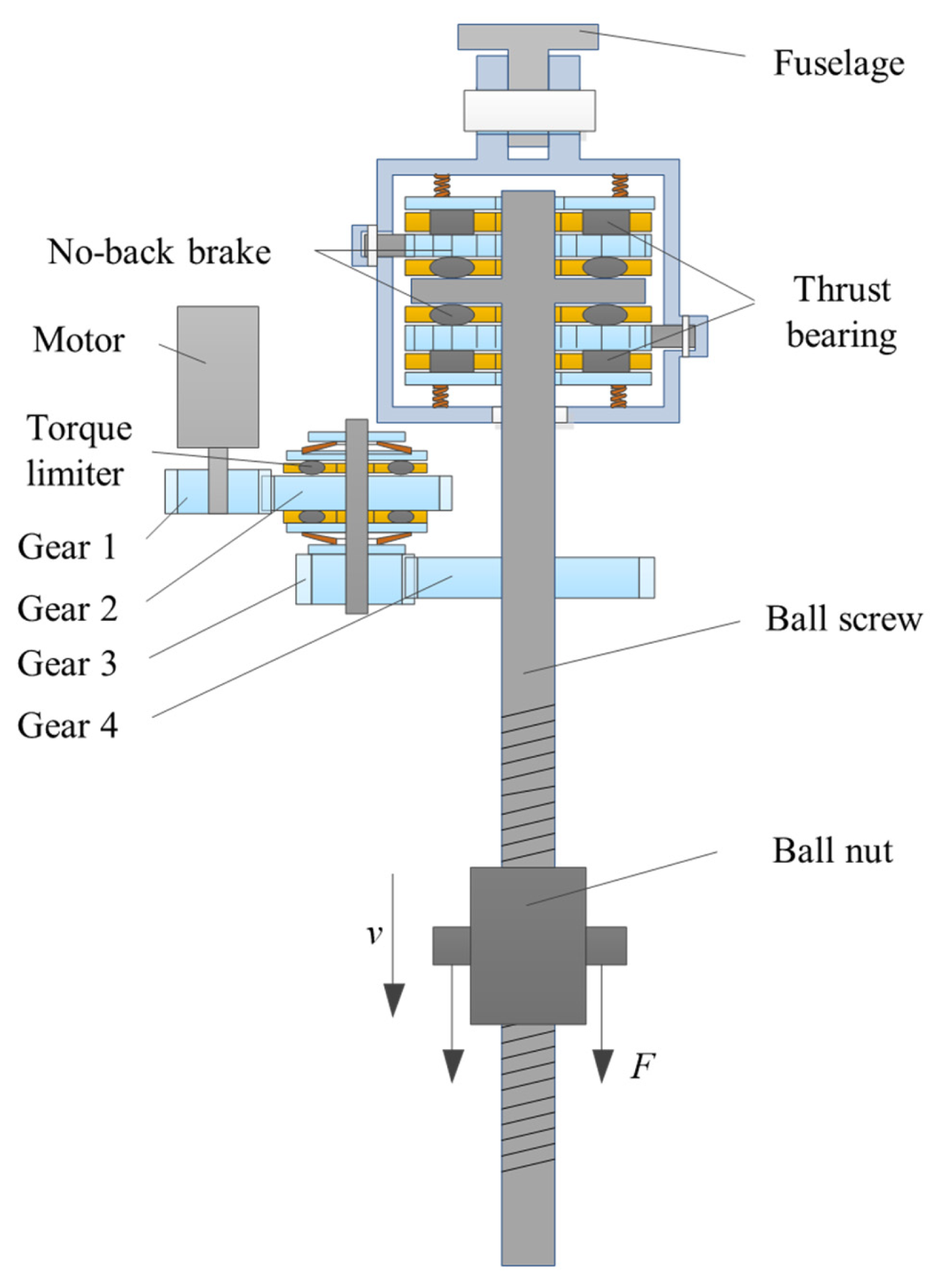
The horizontal stabilizer trim actuator (HSTA) is a key component of an aircraft’s flight control system. It primarily drives the deflection of the horizontal stabilizer, thereby effectively controlling the aircraft’s pitching moment and playing a critical role in ensuring flight stability and safety [1,2,3]. The HSTA is composed of a motor, reducer, screw-nut assembly, torque limiter and no-back brake, as shown in Figure 1. Among these components, the no-back brake serves as a key safety device. During normal operation, as the HSTA drives the movement of the horizontal stabilizer to deflect, the no-back brake must allow the ball screw to rotate freely with minimal resistance torque (ideally approaching zero). When driving ceases, the no-back brake must counteract the torque exerted on the ball screw by the horizontal stabilizer under the aerodynamic loads, preventing reverse transmission to ensure the reliable support for the horizontal stabilizer and the safety of the HSTA system.
Currently, several types of no-back brakes are widely used, including ratchet type [4], roller type [5], friction disc type [6], and spring type [7]. In this paper, a bidirectional no-back brake based on skewed roller thrust bearings (SRTBs) and ratchets was designed. This device has the advantages of simple structure, precise positioning, high load capacity, and high reliability, making is particularly suitable for the HSTA applications.
The roller axis direction is a core parameter in the roller bearing structural design, directly determining the bearing’s contact form, force distribution characteristics, and application scenarios. The design of conventional roller bearings typically aims to minimize resistance torque; therefore, optimizing the roller axis direction is essential to ensure pure rolling contact between the rollers and the raceways. For instance, the roller axis of cylindrical roller bearings is parallel to the bearing’s rotational axis, while that of thrust roller bearings is perpendicular to and intersects with the rotational axis. However, under actual operating conditions, roller skewing occurs due to factors such as the geometry imperfections, misalignment, and external load fluctuations. This transforms the friction form between the rollers and the raceways into rolling-sliding friction, which not only changes the stress distribution and temperature rise characteristics of the rollers but also significantly increases the bearing resistance torque [8,9,10]. In contrast, the skewed roller bearing studied in this paper achieves its operational function by leveraging the characteristic of increased friction torque caused by roller skewing. During its operation, there is both relative rolling and accompanying relative sliding between the rollers and the raceways.
The skewed roller bearings first emerged in the product samples of THK Co., Ltd. and were initially employed as clutches [11]. Early research on this structure focused on the raceway surface, demonstrating that the surface can be represented by a standard single-leaf hyperboloid of revolution. Feng et al. [12] disclosed the self-lock conditions of the skewed roller bearing, and analyzed the three-dimensional contact stress between the rollers and the raceways, the roller profiling method under dry and wet lubrication conditions, as well as the film-forming conditions and parameter influences of elastohydrodynamic lubrication in the mixed lubrication state. Duan et al. [13] conducted a nonlinear analysis on the contact stress of the skewed roller bearings, obtaining the variations in maximum contact stress with different parameters. The results showed that the contact stress decreases with the increment of skew angle.
The aforementioned studies primarily focus on radial-type skewed roller bearings. Feng et al. [14] was the first to conduct a systematic study on the thrust type structure, i.e., SRTBs. Compared with the radial type, SRTBs feature a simpler raceway surface and a compact structure, enabling a wider range of application scenarios.
In this study, the application of SRTBs in the bidirectional no-back brake was investigated. A theoretical model for analyzing the bearing resistance and friction characteristics was established, and the influences of roller centre position and skew angle on the bearing resistance torque were analyzed. A dedicated test platform was developed to verify the reliability of the theoretical model and results. To minimize the contact stress, a combined optimization of the roller crown drop and straight segment length was conducted. Furthermore, the overall deformation and stress distribution of the no-back brake were analyzed with the consideration of the coupled deformation of the ratchet disc and the rod shoulder. The research can provide valuable references for the design and use of SRTB and no-back brakes.

2. No-Back Brake

2.1. Device Structure

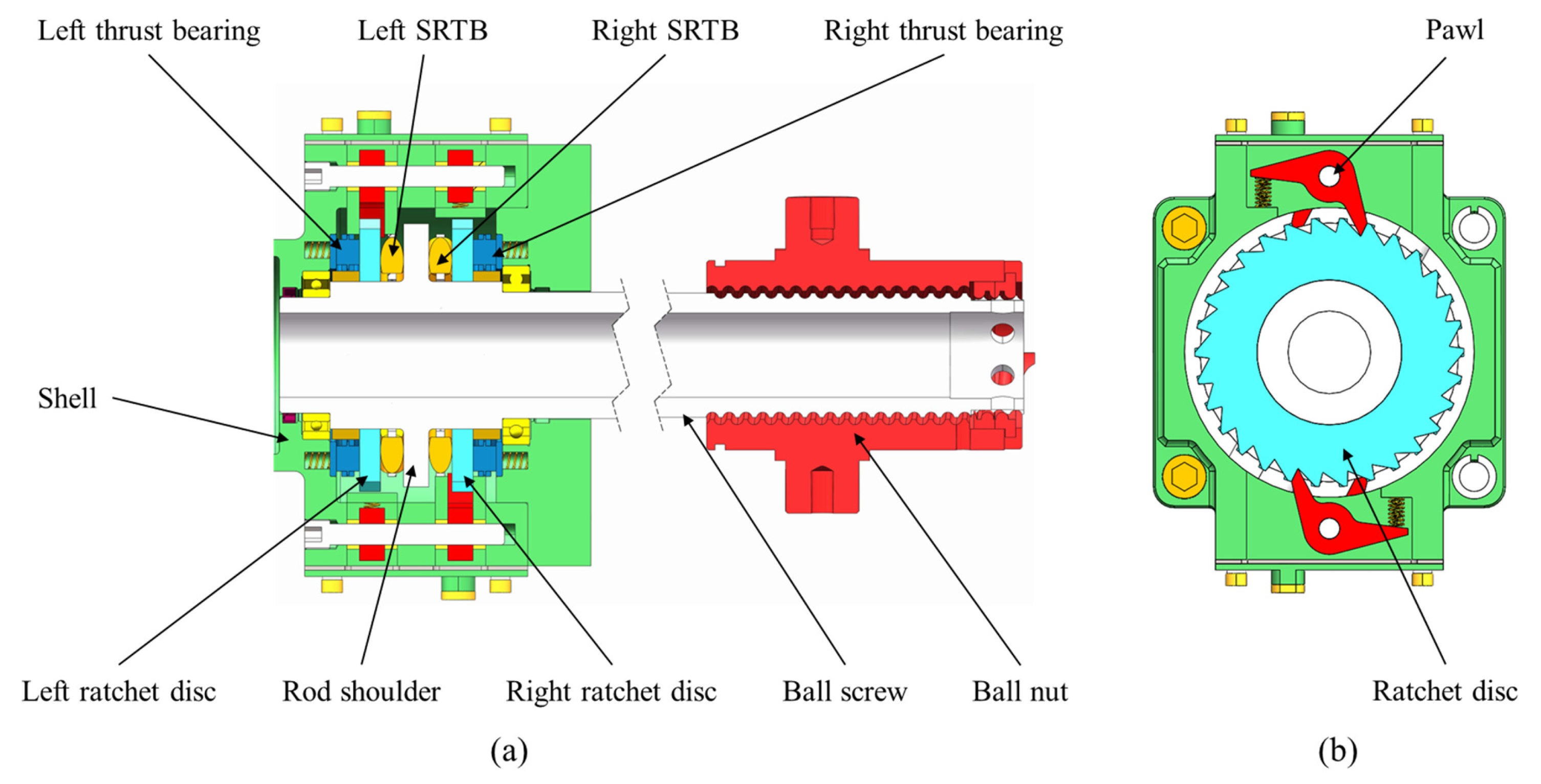
Figure 2 shows the schematic diagram of the no-back brake, which mainly consists of two SRTBs, two thrust bearings, two journal bearings, two sets of ratchet and pawls, and shell. A rod shoulder structure is designed on the ball screw. An SRTB is installed on each side of the rod shoulder structure to provide a stable resistance torque. Thrust bearings are designed on the outer sides of the SRTBs. To prevent reverse rotation, a ratchet disc is designed between the SRTB and the thrust bearing, and a pawl is equipped to permit the ratchet disc to rotate in only one direction. Specifically, the ratchet and pawl assembly on the left can restrict the left SRTB from rotating counter-clockwise, and the ratchet and pawl assembly on the right can restrict the right SRTB from rotating clockwise.
The shell of the no-back brake is attached to the aircraft fuselage via a universal joint assembly. The ball screw is capable of performing bidirectional rotational motion under the drive of the HSTA driving device. The driving torque exerted by the driving device on the ball screw is Td. When the HSTA drives the ball screw to rotate in the clockwise direction, it can push the ball nut to move rightward. While when the HSTA drives the ball screw to rotate in the counter-clockwise direction, it can push the ball nut to move leftward. During the movement, the aerodynamic load acting on the horizontal stabilizer is transferred to the ball screw through the ball nut. This load can be decomposed into the force Fg along the ball screw and the torque Tg around the ball screw. The force and torque applied by the no-back brake on the ball screw are Fb and Tb, respectively.
The forces and torques on the ball screw need to satisfy the following relationship
F g = F b T d = T g + T b
When the horizontal stabilizer is in an untrimmed state, the forces and torques are analyzed under different combinations of aerodynamic force directions and ball nut movement directions.
When the aerodynamic force of the horizontal stabilizer acts to the left and the HSTA needs to drive the ball nut to move to the right, the aerodynamic force is supported by the SRTB and the thrust bearing located on the left of the rod shoulder. As the left ratchet and pawl assembly does not restrict the clockwise rotation of the SRTB, both the left-hand SRTB and the thrust bearing can rotate under the action of the frictional force between them. Owing to the small friction coefficient of the thrust bearing, the frictional resistance torque between it and the ball screw is small and can be neglected. Meanwhile, the right SRTB cannot rotate due to the restriction of the ratchet and pawl, and the rod shoulder and its rollers are in a state of sliding friction. Nevertheless, since the axial load it bears is small, the frictional resistance torque generated is also minimal. Therefore, the frictional resistance torque between the no-back brake and the ball screw is negligible. The driving torque of the HSTA mainly overcomes the aerodynamic torque of the horizontal stabilizer, namely:
T d T g
When the aerodynamic load on the horizontal stabilizer is still directed to the left, and the HSTA needs to drive the ball nut to move to the left, the aerodynamic force still acts on the left SRTB and the thrust bearing. However, the left SRTB cannot rotate due to the action of the ratchet and pawl assembly. The rod shoulder and the rollers of the SRTB are in a state of sliding friction. Although the right SRTB and the thrust bearing can rotate, the axial load they bear is relatively small, resulting in a very small frictional resistance torque. Meanwhile, the aerodynamic moment Tg of the horizontal stabilizer is in the same direction as the driving moment Td, and the aerodynamic moment serves as an assisting force for the movement of the ball nut. The moments acting on the ball screw are as follows:
T d + T g = T b
In this condition, the driving device of HSTA only needs to supply a very small driving torque, or even no driving torque is required. Specifically, if the aerodynamic torque exceeds the frictional resistance torque Tb that the no-back brake can offer, the driving device might even be driven in the reverse direction. To enhance the stability and reliability of the HSTA, the driving torques provided during its bidirectional driving ought to be consistent, namely, Td remains constant. By rearranging Equations (2) and (3), the following can be derived:
T b 2 T g
It can be obtained that the frictional resistance torque that the SRTB can provide should be twice the aerodynamic moment.
The above describes the force and torque of the no-back brake when the aerodynamic load on the horizontal stabilizer acts to the left. Similarly, when the aerodynamic load on the horizontal stabilizer acts to the right, the right SRTB is in the working state. Its frictional resistance torque and the aerodynamic torque acts on the horizontal stabilizer still satisfy Equation (4).
When the horizontal stabilizer is in the trimmed state, the HSTA drive device ceases operation, and the driving torque becomes zero. When the horizontal stabilizer experiences a left-ward disturbing aerodynamic force, the ball nut moves leftward under the effect of the aerodynamic torque, and the ball screw tends to rotate counter-clockwise. At this moment, the left SRTB bears the aerodynamic force and remains non-rotatable. It utilizes the static friction resistance torque between itself and the rod shoulder of the ball screw to counter the aerodynamic torque and prevent the reverse drive of the HSTA. Similarly, if the disturbing aerodynamic force acting on the horizontal stabilizer is directed rightward, the static friction between the right SRTB and the rod shoulder of the ball screw can prevent the reverse drive of the HSTA. Evidently, after the HSTA drive stops, the no-back brake can still counterbalance the disturbing aerodynamic force on the horizontal stabilizer, prevent reverse transmission, and guarantee the stability and safety of the HSTA system.

2.2. SRTB

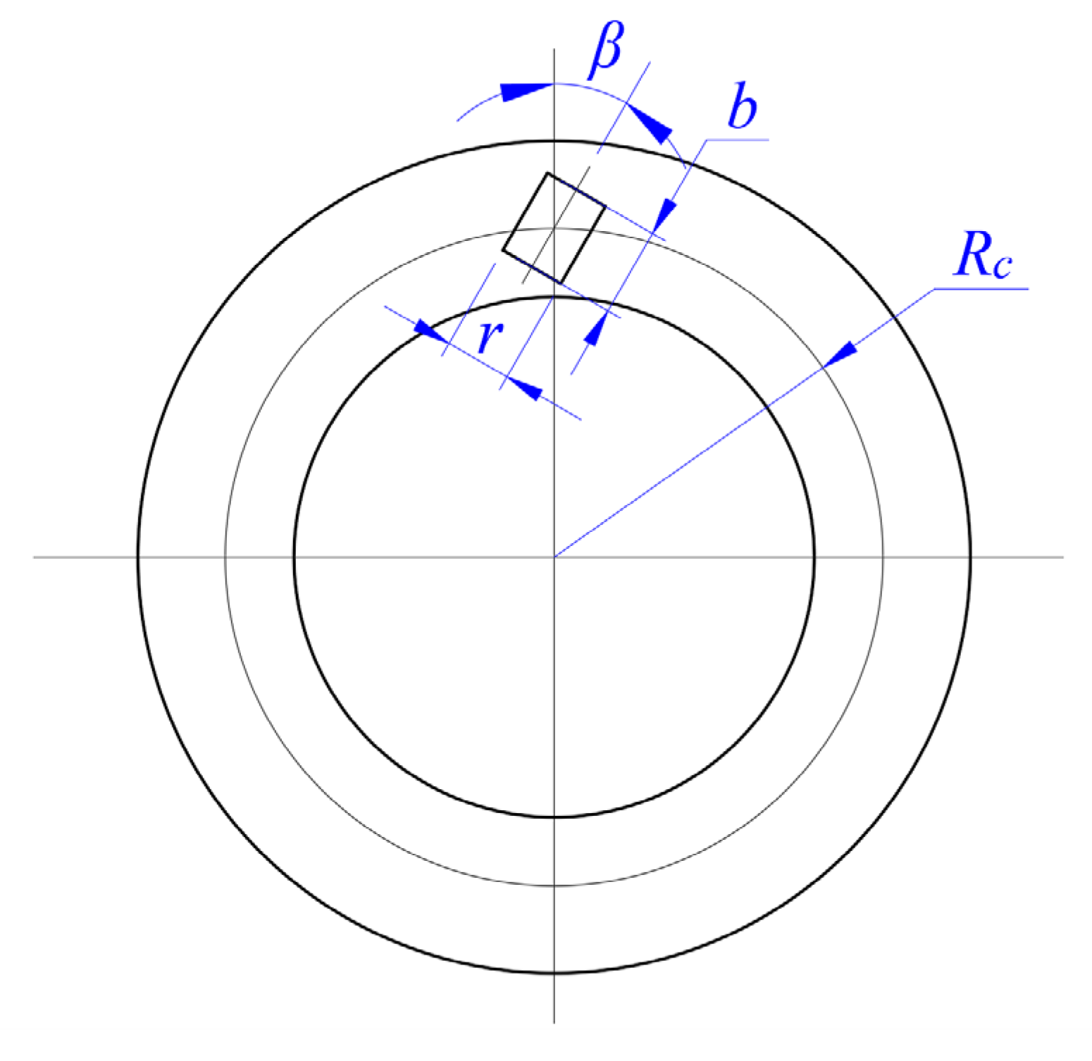
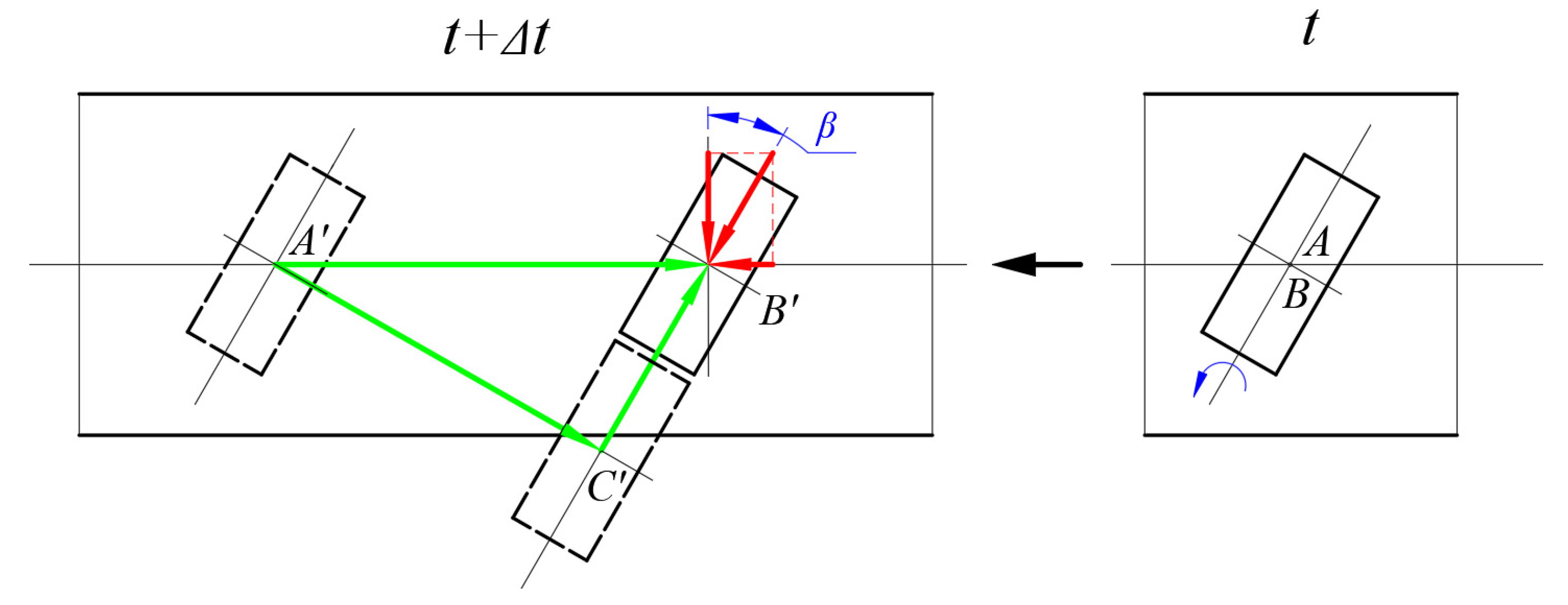
The structure of the thrust type SRTB is shown in Figure 3. Its structure is similar to that of the common roller thrust bearing with needles. However, there is a skew angle β between the axis of the roller and the radial direction of the bearing. This geometric characteristic alters the roller’s motion behaviour, as shown in Figure 4. In the figure, green arrows indicate the movement of the roller, while red ones represent the force exerted on the roller. Points A and B denote specific locations on the rotating disc and the roller, respectively. At time t, point A coincides with point B. After a time interval ∆t, i.e., at time t + ∆t, the rotating disc moves to position A′, and the roller moves to position B′. The roller moves relative to the rotating disc from A′ to B′. This motion can be decomposed into a rolling-sliding composite motion from A′ to C′ and a sliding motion from C′ to B′. Since the motion from A′ to C′ is predominantly rolling—and given that the rolling friction coefficient is significantly lower than the sliding friction coefficient—the friction force during this motion is considered negligible. The sliding friction force acting on the roller from C′ to B′ acts along the roller’s axial direction, and its component in the direction of AB′ contributes to the bearing’s frictional resistance torque. The magnitude of this torque is
T = μ W R c sin β
where μ is the sliding friction coefficient between the roller and disc, W is the external load on the roller, Rc is the radius where the roller centre is located.
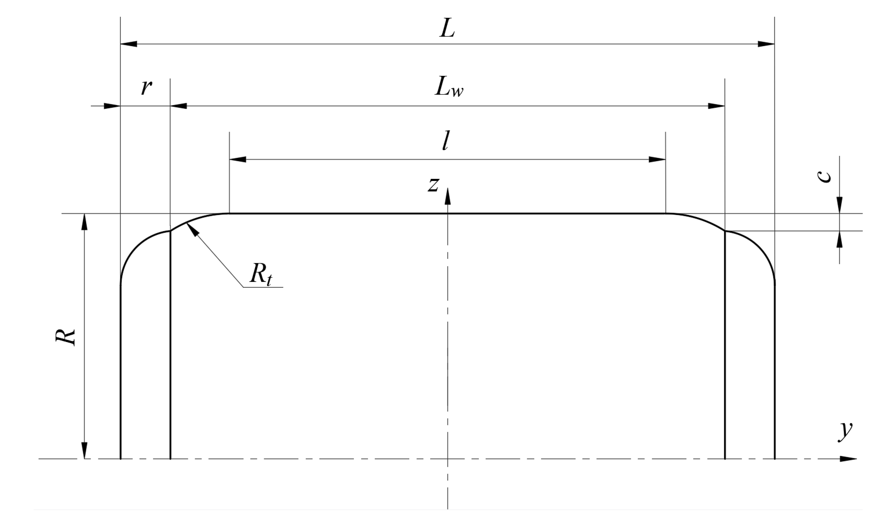
To improve the performance of bearings, the rollers are often profiled to optimize the contact stress distribution and mitigate the edge stress concentration, thus extending the fatigue life [15]. In this paper, a tangent arc is employed to profile the rollers, as depicted in Figure 5. R is the nominal roller radius, L is the roller length, and fillets with radius r are designed on both ends. Lw denotes the effective length of the roller, l represents the length of the straight segment, Rt is the radius of the correction arc, and c refers to the crown drop. The modification equation is given as follows:
z = 0 y < 0.5 l R t R t 2 y 0.5 l 2 0.5 l y < 0.5 L w
The relationship between the roller crown drop c and the profiling arc radius Rt is as follows:
R t L w l 2 8 c

3. Resistance Torque Characteristics

3.1. Influence of Bearing Parameters

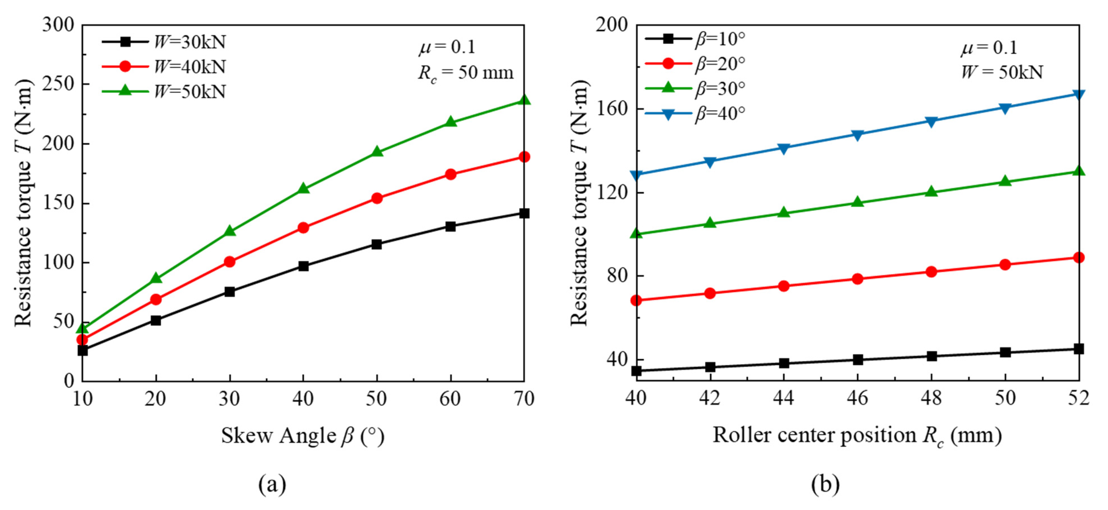
The variation in the frictional resistance torque of the SRTB with respect to its structural parameters is illustrated in Figure 6. As shown in Figure 6a, an increase in the skew angle leads to a gradual rise in the bearing resistance torque. This trend can be attributed to the fact that varying the skew angle not only modifies the effective friction arm but also alters the relative proportion between rolling and sliding motion modes of the rollers. At small skew angles, the rollers predominantly undergo motion close to pure rolling. Given the inherently low rolling friction coefficient, the resulting resistance torque remains relatively low. With increasing skew angle, however, the contribution of sliding motion becomes more significant. Since the sliding friction coefficient is substantially higher than that of rolling, the overall resistance torque increases accordingly. Figure 6b presents the relationship between the bearing resistance torque and the radial position of the roller centre. It is evident that, under all considered skew angles, the resistance torque increases monotonically with Rc.
According to the operational requirements of a specific type of no-back brake, the parameters of the SRTB are defined as listed in Table 1.

3.2. Experimental Study

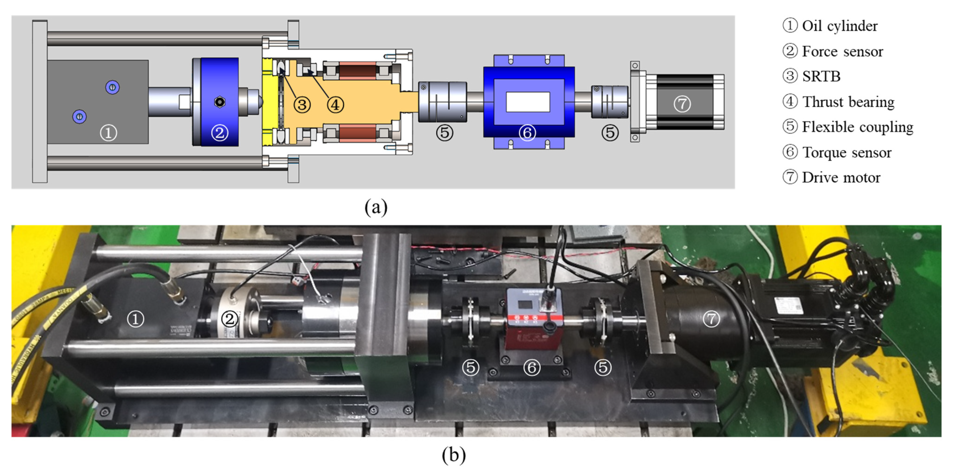
To characterize the resistance torque of the SRTB, a test platform was developed. As shown in Figure 7, the platform mainly consists of loading oil cylinder, force sensor, tested SRTB, thrust bearings, torque sensor, flexible couplings, and drive motor. The oil cylinder (CX-SD80X90-N, Hongfeng Hydraulics Co., Ltd., Fuyang, China) is positioned on the left side, capable of exerting an axial load of no less than 50 kN. A force sensor (DYLF-102, Dayang Sensor System Engineering Co., Ltd., Bengbu, China) is installed between the oil cylinder and the tested SRTB. This sensor ensures high-precision measurement of the applied load, with a measuring range of 100 kN and a test accuracy of 0.05%. The axial force is transmitted to the tested bearing through the loading oil cylinder, force sensor, and left-side shaft housing. The drive motor (130ST, Pufede Electromechanical Co., Ltd., Hangzhou, China) is located on the right side. It drives the tested bearing to rotate via a flexible coupling. A high-precision dynamic torque sensor (DYN-200, Dayang Sensor System Engineering Co., Ltd., Bengbu, China) is used to measure the bearing’s resistance torque. This torque sensor has a measuring range of 200 Nm and a test accuracy of 0.1%. Additionally, the thrust bearing and journal bearing on the right side of the tested SRTB are responsible for positioning and supporting the rotating shaft. During experiments, the tested SRTB was lubricated with Castrol Aero 40 lubricating oil. All resistance torque measurements were conducted under ambient temperature conditions.
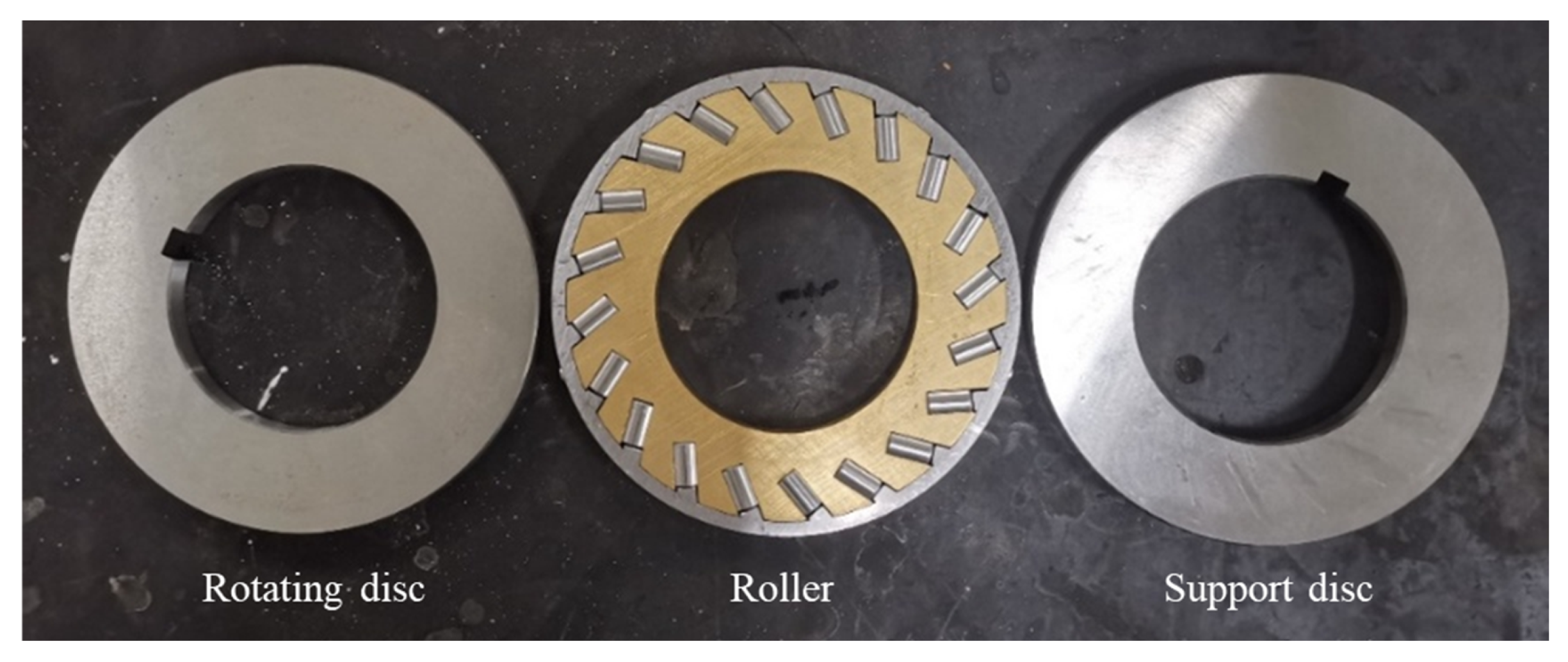
Figure 8 shows the tested SRTB. The rollers, rotating disc, and support disc of the SRTB are fabricated from GCr15 bearing steel, selected for its superior wear resistance and mechanical stability. To further enhance its mechanical performance, quenching heat treatment was applied to these components. After heat treatment, the Rockwell Hardness C (HRC) of the components was controlled within the range of 58–62, which satisfies the material strength requirements for withstanding the applied axial load and contact stresses. Subsequently, all components underwent precision grinding to ensure superior surface quality and dimensional accuracy. This machining process achieves a surface arithmetic mean deviation (Ra) of 0.1 μm. For the rollers, their dimensional accuracy is strictly maintained within ±1.5 μm, ensuring consistent contact geometry between the rollers and discs across the entire bearing assembly.
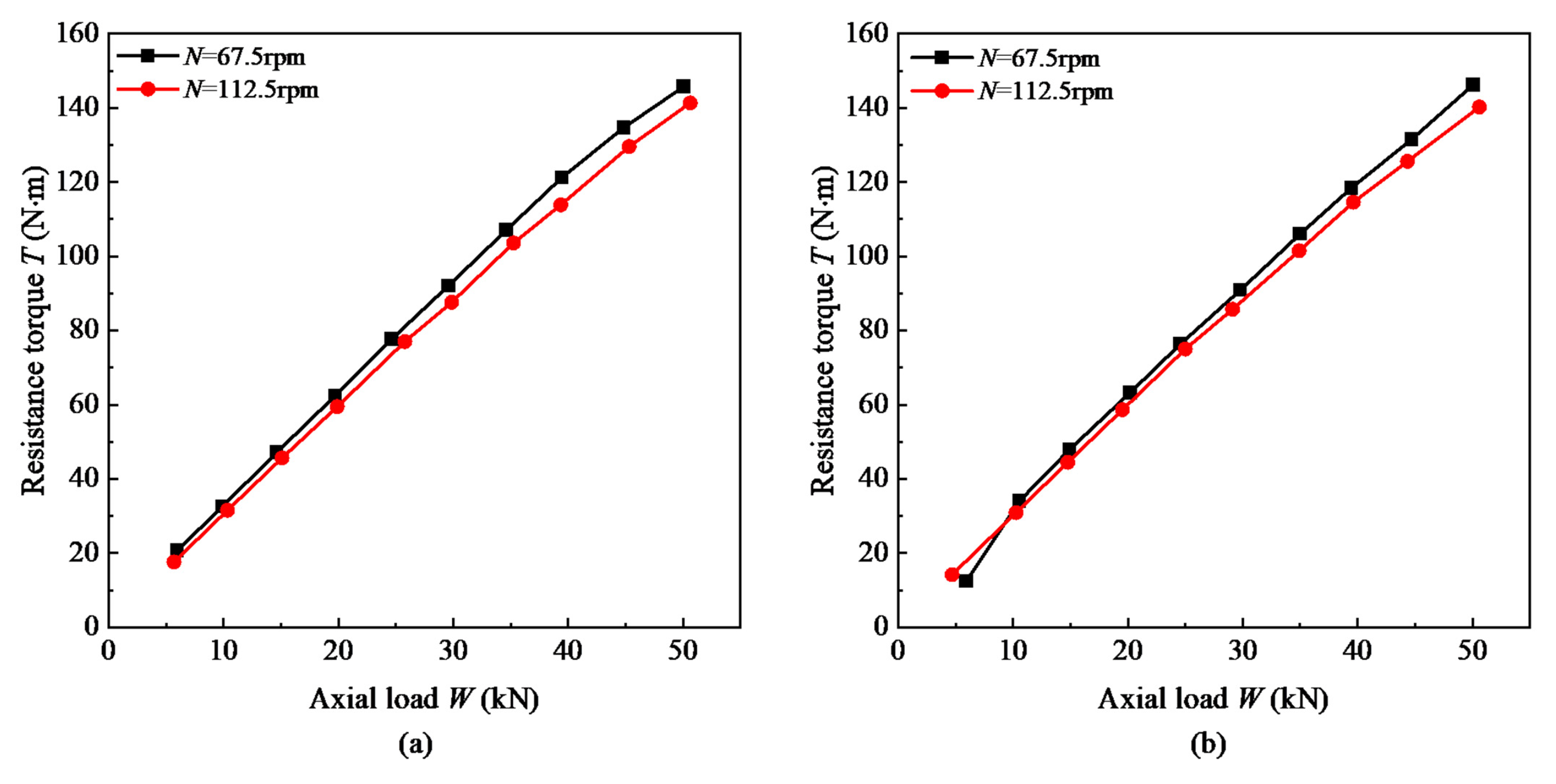
The SRTB was tested under four working conditions: rotational speeds of 67.5 rpm and 112.5 rpm, with both forward and reverse rotation directions. For each working condition, three repeated tests were conducted, and the average value of the three test results was taken as the experimental value. The variation in the measured resistance torque with the load obtained in the experiment is shown in Figure 9. It can be observed that the bearing resistance torque increases linearly with increasing axial load, and this trend remains consistent across both rotational speeds. At 67.5 rpm, the maximum axial loads were 50,078 N (forward rotation) and 50,637 N (reverse rotation), the corresponding resistance torques were 145.8 Nm and 146.3 Nm. Based on Equation (5), the calculated friction coefficients between the bearing and the rotating disc were 0.1259 and 0.1263, respectively. At 112.5 rpm, the maximum axial loads were 50,637 N and 50,607 N, with corresponding resistance torques of 141.4 Nm and 140.3 Nm. The resulting friction coefficients were 0.1208 and 0.1200, respectively.
The errors in the test results are primarily composed of random errors and systematic errors. Random errors were mitigated by adopting the average values of the measured results. Systematic errors mainly originate from instrumental errors, which in this study are attributed to the force sensor and the torque sensor with accuracies of 0.05% and 0.1%, respectively. When calculating the friction coefficient, the test error was approximately 0.15%. This error magnitude is relatively small and does not compromise the theoretical and experimental analysis of the SRTB.
The experimental results demonstrate that the friction coefficients of the SRTB under forward and reverse rotations are nearly identical (variation within 0.3%), indicating negligible directional dependence. Furthermore, higher rotational speeds lead to slightly lower resistance torque and friction coefficient compared to lower speeds. At 112.5 rpm, the friction coefficient is approximately 4% lower than that at 67.5 rpm. This phenomenon is attributed to the improved lubrication state. Under oil-lubricated conditions, an increase in rotational speed facilitates more efficient delivery of lubricating oil to the contact zone between the rollers and the rotating disc. This enhances oil film formation, reduces localized high-pressure regions, strengthens the elastohydrodynamic lubrication effect, and ultimately decreases frictional resistance.

4. Bearing Stress Analysis

4.1. Analysis Model

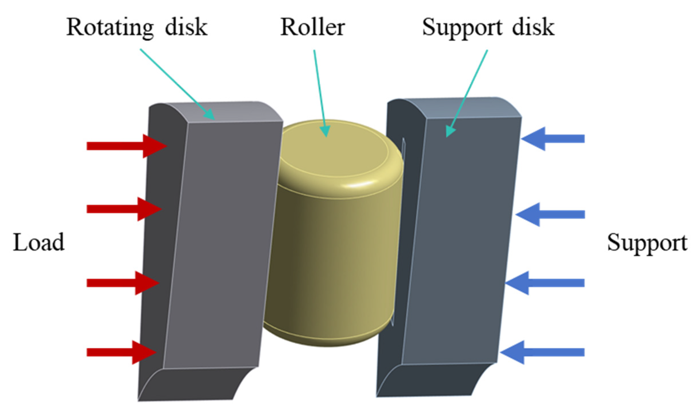
Given the significant axial load exerted on the no-back brake, concerns regarding the stress distribution within the SRTB—particularly localized stress on its rollers—are of paramount importance. Accordingly, this study investigates the contact stress characteristics of the SRTB and develops a finite element analysis model encompassing the rotating disc, support disc, and rollers, as shown in Figure 10. The key considerations and simplifying assumptions adopted in the modelling are outlined as follows:
(1)
Model simplification: The SRTB is configured with 20 rollers. To balance computational efficiency and analytical accuracy, a 1/20 cyclic symmetry model was employed for numerical simulation. The simplified model comprises one roller, a 1/20 segment of the rotating disc, and a 1/20 segment of the support disc, which retains the core contact mechanics of the full-scale assembly.
(2)
Periodic boundary conditions: Periodic boundary conditions were imposed on the two circumferential cross-sections of both the rotating disc and the support disc. This setup replicates the structural continuity and load transfer characteristics of the complete bearing assembly, ensuring the cyclic symmetry model is representative of the full-scale system.
(3)
Rotational speed: The rotational velocity was assigned to the rotating disc.
(4)
External load application: An axial load of 2500 N was applied to the left end surface of the rotating disc.
(5)
Support constraint: The right end surface of the support disc was subjected to a fixed support constraint to mimic the real-world installation scenario, where the support disc is rigidly mounted in the fixed housing.
(6)
Contact condition: The contact interactions between the rollers and the rotating/support discs were defined as dry frictional contact with a friction coefficient of 0.12. The influence of lubricating oil on contact stress was neglected in this model, a simplification justified primarily by the relatively low operating speed of the bearing. At such low speeds, the hydrodynamic effect and elastohydrodynamic effect of the lubricating oil are insignificant, and thus their impact on the contact stress distribution is deemed negligible.
(7)
Material: The materials of the rollers, support plates and rotating plates are all GCr15. The Poisson’s ratio and Young’s modulus of the material are set to be 0.3 and 208 GPa, respectively.
Figure 10. Theoretical model of SRTB.
Machines 14 00132 g010
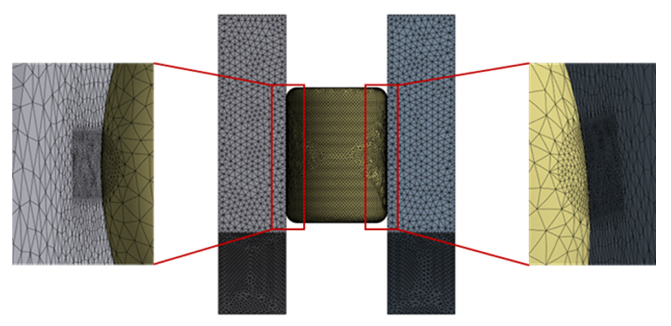
The open-source finite element analysis software ElmerFEM (Version 9.0, CSC—IT Center for Science Ltd., Uusimaa, Finland) is used in this paper. In the finite element analysis of contact stress, the mesh size and number in the contact area significantly affect the accuracy and efficiency of the calculation results. Therefore, mesh independence verification is essential. In this study, the default mesh size for the entire bearing is 0.3 mm, and the contact area is refined, as shown in Figure 11. Table 2 shows the node numbers and contact stresses under different mesh sizes in the refined contact area. Here, σR is the maximum contact stress between the roller and the rotating disc, and σS is the maximum contact stress between the roller and the support disc. The results show that as the mesh size in the contact area decreases, the contact stress between the roller and both the rotating disc and the support disc gradually increases. When the mesh size is reduced from 0.05 mm to 0.04 mm, the number of nodes increases by 43%, but the change in roller contact stress is less than 2%. At this point, the influence of mesh size on the results is negligible, indicating that a mesh-independent solution has been obtained. To balance calculation accuracy and efficiency, the mesh size in the contact area for the calculations in this paper is determined to be 0.05 mm.

4.2. Influence of Crown Parameters

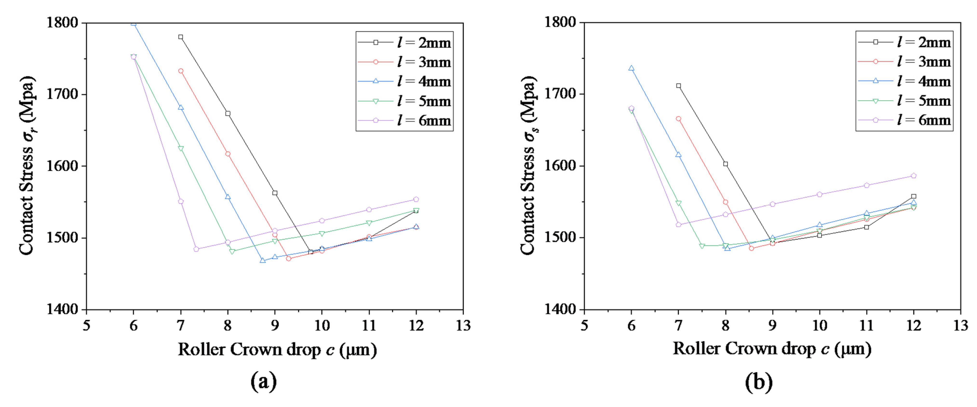
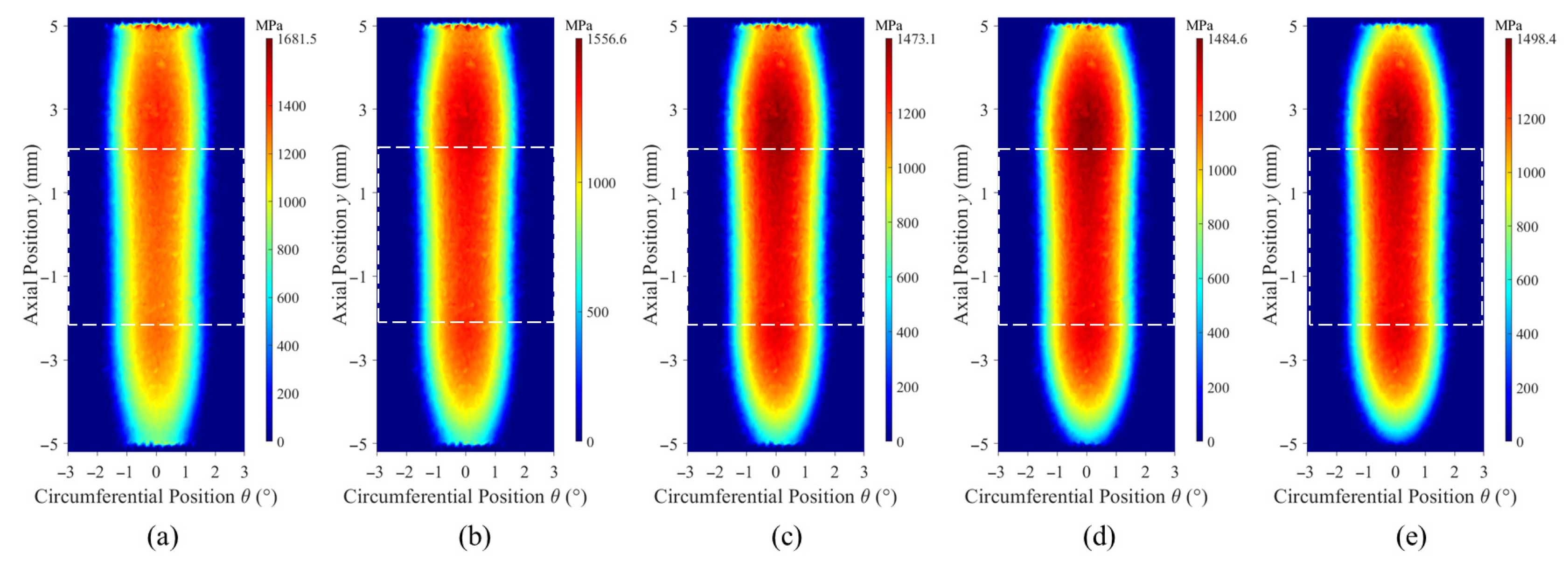
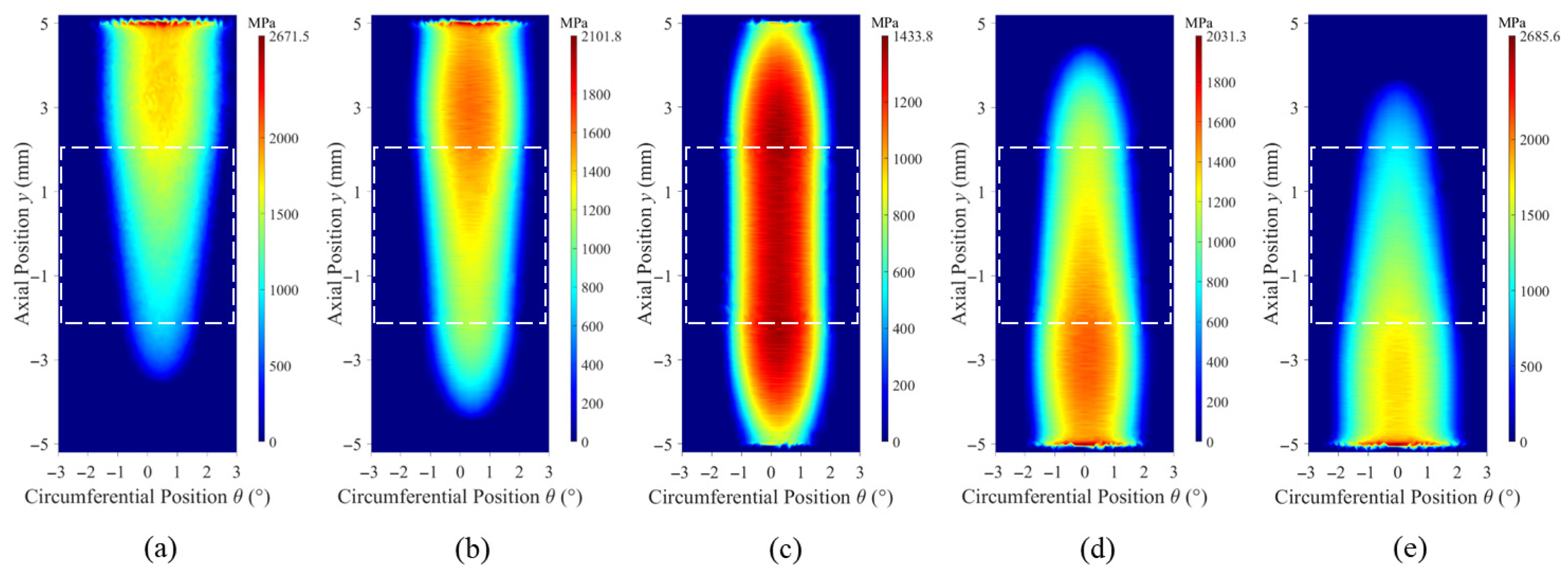
The variation in the maximum roller contact stress with the crown drop is shown in Figure 12. It can be seen that under different straight segment length conditions (l = 2, 3, 4, 5, 6 mm), the roller contact stress initially decreases sharply and then increases gradually with increasing crown drop, indicating the existence of an optimal value of the crown drop. To further elucidate this variation trend, Figure 13 presents the contact stress contours between the roller and rotating disc under different crown drop values. The area within the white wireframe is the straight segment area. Since the roller profiling adopts a combined design of a tangent arc and a straight segment, shape mutations occur at both the roller ends and the junctions between the straight segment and arc segments, leading to stress concentration at these two locations. When the crown drop is small, the shape transition gradient at the roller ends is significant, resulting in a pronounced stress concentration effect. As the crown drop increases, the end-related stress concentration is alleviated, and the maximum contact stress is substantially reduced. However, the stress concentration at the straight-arc junctions gradually intensifies, leading to the increment in the contact stress. Collectively, these observations confirm the existence of an optimal crown drop that achieves a more uniform distribution of roller contact stress.
As illustrated in Figure 12a, when the straight segment length increases from 2 mm to 6 mm, the optimal crown drops for minimizing the roller-rotating disc contact stress are 9.8 μm, 9.3 μm, 8.7 μm, 8.1 μm, and 7.3 μm, with corresponding minimum contact stresses of 1480.4 MPa, 1471.2 MPa, 1468.1 MPa, 1481.5 MPa, and 1484.4 MPa. These results demonstrate that the minimum contact stress first decreases and then increases with increasing straight segment length, yielding optimal values of 4 mm (straight segment length) and 8.7 μm (crown drop). The same variation trends are observed for the roller-support disc contact stress, as shown in Figure 12b. A marginal variation in the optimal crown drop (8.0 μm) is noted in this case, while the optimal straight-section length remains unchanged at 4 mm.
Notably, Figure 12 further reveals that when the crown drop is less than the optimal value, the rate of roller stress reduction is more prominent than the rate of stress increase observed when the crown drop exceeds the optimal value. This phenomenon indicates that the influence of crown drop on the stress at the roller ends is greater than its effect on the stress at the straight-arc junctions. This discrepancy is primarily attributed to the more severe shape mutation at the roller ends, whereas the shape transition at the straight-arc junctions is relatively gradual. This result can provide a reference for determining the machining error of the roller. The tolerance range of the crown drop should take the optimal value as the lower limit. In this case, the tolerance range of the crown drop is 8 μm to 11 μm.
Furthermore, it can be observed from Figure 13 that the contact stress on the outer side of the roller is significantly higher than that on the inner side. This discrepancy is primarily attributed to the uniformly distributed axial load applied to the rotating disc: specifically, the outer region of the disc has a larger bearing area and thus sustains a proportionally higher load, which induces bending deformation of the rotating disc. Figure 14 shows the typical axial deformation of the SRTB. The axial deformation in the outer region is 0.021 mm, while that in the inner region is 0.01 mm. This deformation discrepancy corroborates the bending deformation of the rotating disc, which directly contributes to the uneven contact stress distribution observed on the roller.

5. Analysis of No-Back Brake Component

In previous theoretical analyses and experimental investigations, the external load was assumed to act uniformly on the surface of the SRTB’s rotating disc. However, under the practical service conditions of the no-back brake, the external load is transmitted to the SRTB’s rotating disc through an adjacent thrust bearing. This transmission path may induce force misalignment between the two sides of the rotating disc. Such misalignment can elicit deformation of the rotating disc, thereby altering the contact stress distribution at the roller-disc interface.
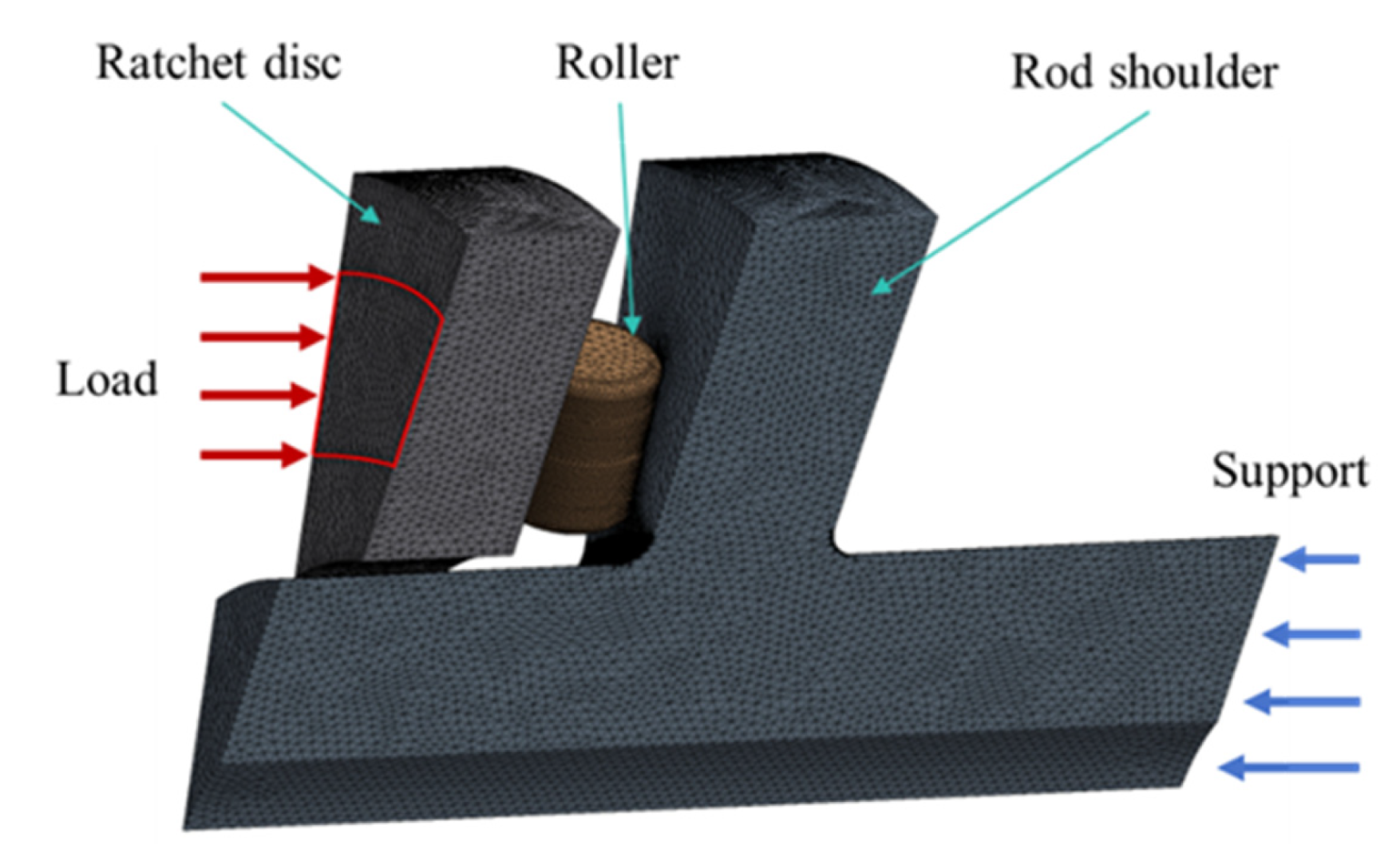
To investigate the stress and deformation characteristics of the no-back brake under practical service conditions, a finite element analysis model of the assembly, including the ratchet disc, rod, and rollers, was established, as shown in Figure 15. Consistent with the simplifying assumptions outlined in Section 4.1, a 1/20 cyclic symmetry model was adopted for numerical simulation to balance computational efficiency and accuracy. Periodic boundary conditions were imposed on the circumferential cross-sections of both the ratchet disc and the rod, while a fixed support constraint was applied to the right end face of the rod. Key geometric parameters of the components are specified as follows: The ratchet disc has inner and outer diameters of 72 mm and 123 mm (thickness: 10 mm), while the rod shoulder features inner and outer diameters of 70 mm and 123 mm (thickness: 12 mm). The no-back brake incorporates an 81216-type thrust bearing, whose contact interface with the ratchet disc forms an annular region with inner and outer diameters of 84 mm and 112 mm. Accordingly, a 2500 N axial load was applied to this annular region, with a load application centre radius of 49 mm. Notably, the roller centre position of the SRTB is 44.25 mm, which is smaller than the load application centre position. This radial offset induces asymmetrical loading on the ratchet disc, generating a torque that causes the disc to bend toward the right.
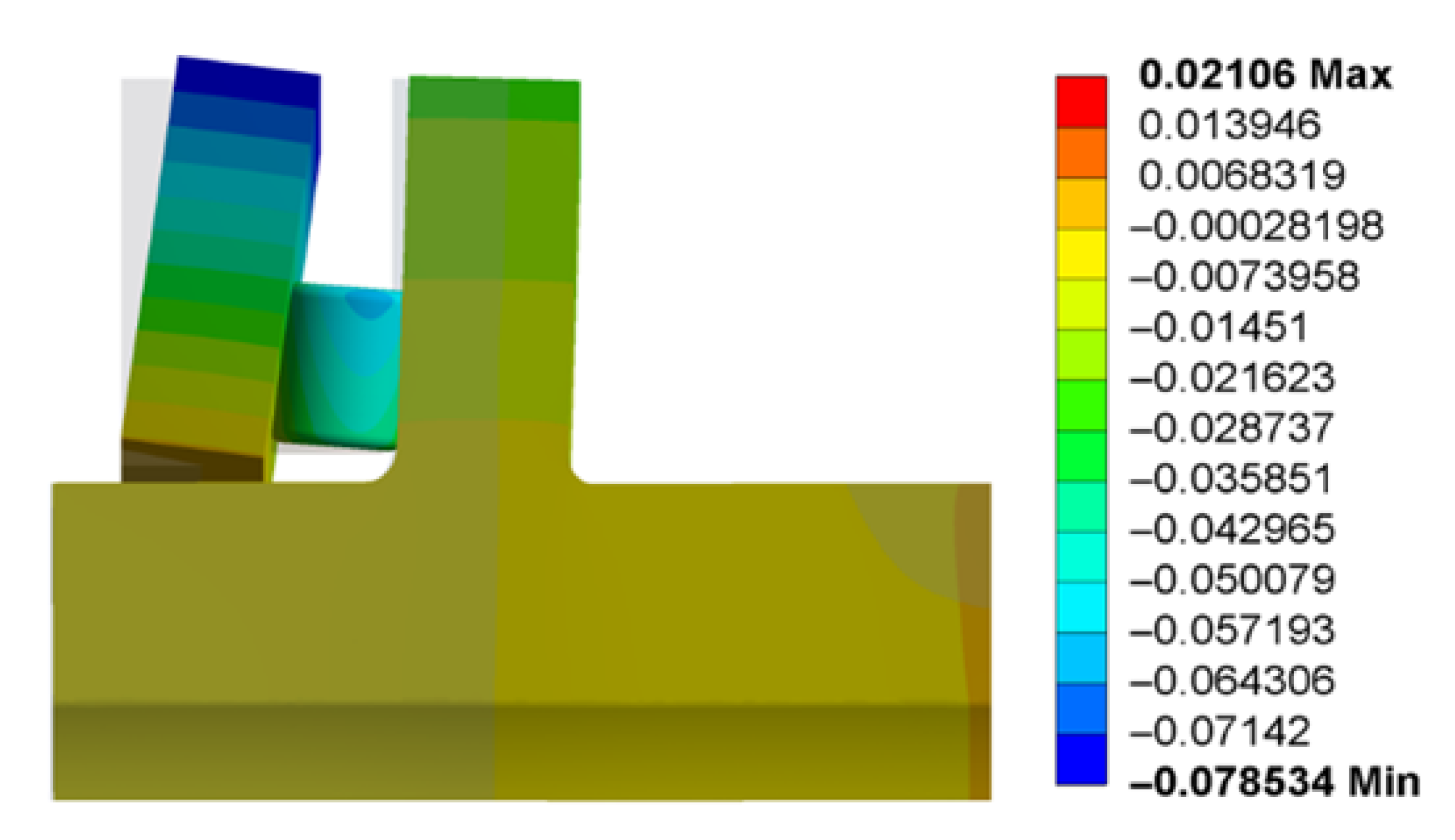
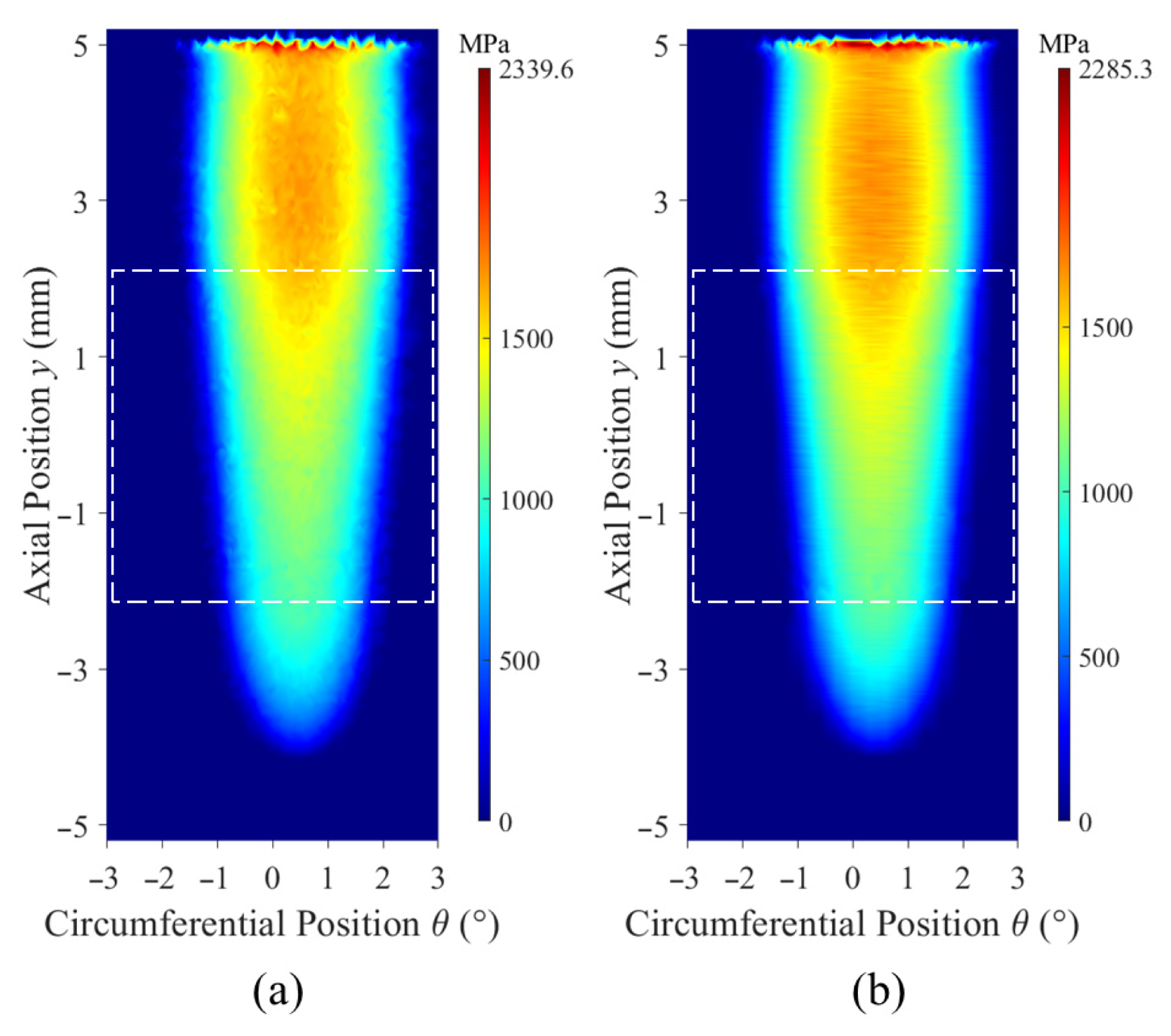
Figure 16 presents the axial deformation of the no-back brake, where the shaded region denotes the undeformed reference configuration. Evidently, under the synergistic effect of the axial load and roller support forces, the ratchet disc undergoes significant rightward bending deformation with a maximum magnitude of approximately 0.078 mm, while the rod shoulder exhibits a maximum deformation of merely 0.023 mm. Such a deformation discrepancy induces an asymmetric contact state between the rollers and the ratchet disc/rod shoulder, as illustrated in Figure 17. Specifically, contact is confined to the region toward the outer circumference of the ratchet disc/rod shoulder, accompanied by obvious stress concentration, whereas no contact occurs on the inner side. The maximum contact stresses between the rollers and the ratchet disc/rod shoulder are 2339.6 MPa and 2285.3 MPa, respectively. Although these values remain below the allowable contact stress limit of the roller material (4000 MPa) [16], the asymmetric contact condition will accelerate roller fatigue and wear, thereby compromising the operational stability and service life of the no-back brake.
To improve the roller’s contact stress distribution, this study investigates the influence of the roller centre position Rc on the deformation and contact stress of the no-back brake components. In the calculations, the roller skew angle β was adjusted accordingly with variations in Rc to maintain a constant resistance torque of the SRTB.
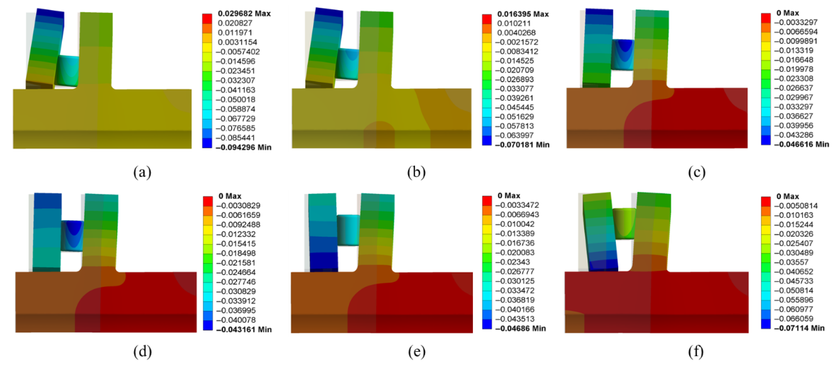
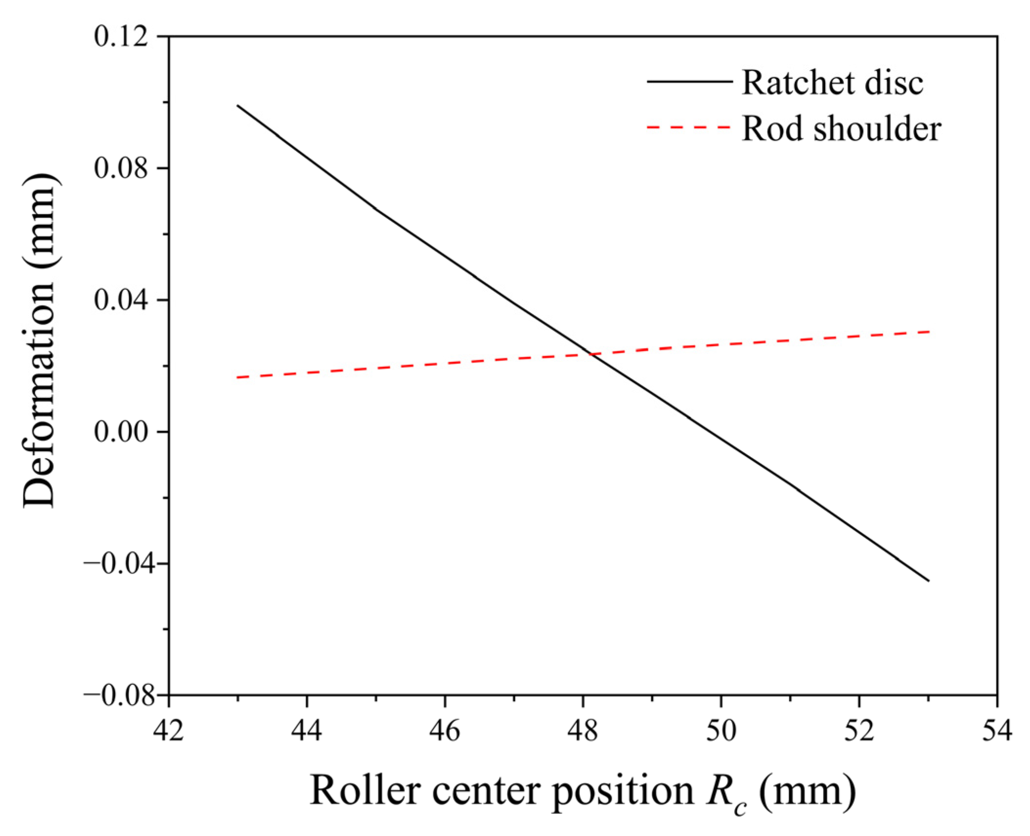
Figure 18 shows the axial deformation contours of the no-back brake under different Rc values, while Figure 19 illustrates the deformation of the ratchet disc and rod shoulder as a function of Rc (with rightward deformation defined as positive). When Rc is less than the load application centre position (49 mm), the ratchet disc is subjected to a counterclockwise bending torque under the combined action of the left-side axial load and right-side roller support forces, inducing rightward bending. As Rc increases, the bending torque gradually diminishes, accompanied by a reduction in the ratchet disc’s bending deformation. When Rc reaches 49.7 mm, the ratchet disc’s bending deformation is eliminated—at this point, the left-side load and right-side roller support forces on the ratchet disc achieve a force-balanced centred state, resulting in zero bending deformation. With a further increase in Rc, the direction of the bending torque reverses under the synergistic effect of the external load and roller support forces, consequently inducing leftward bending of the ratchet disc. The deformation magnitude increases with increasing Rc. The support position of the rod shoulder is fixed and consistently lower than the roller centre position, so the direction of its bending torque remains unchanged. As Rc increases, both the bending torque and deformation of the rod shoulder increase progressively.
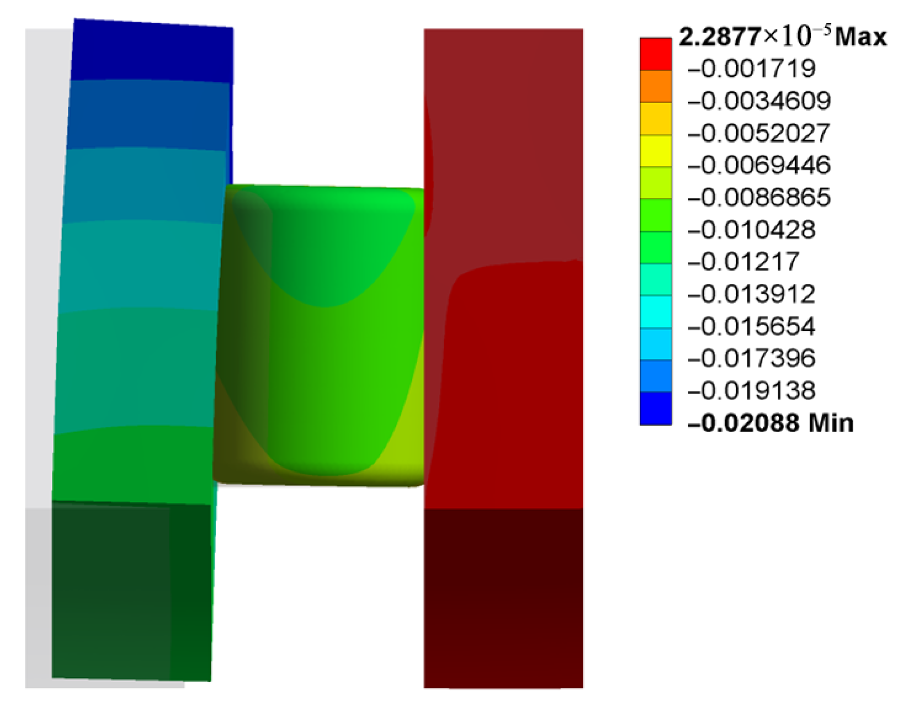
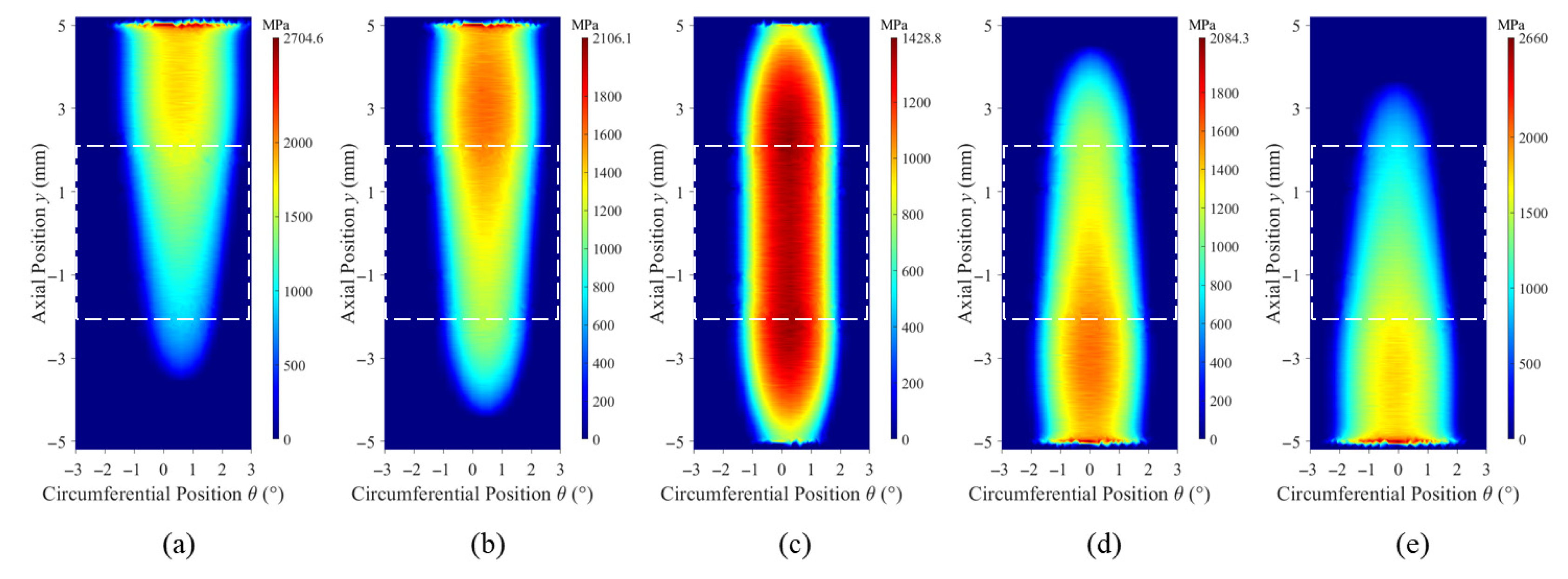
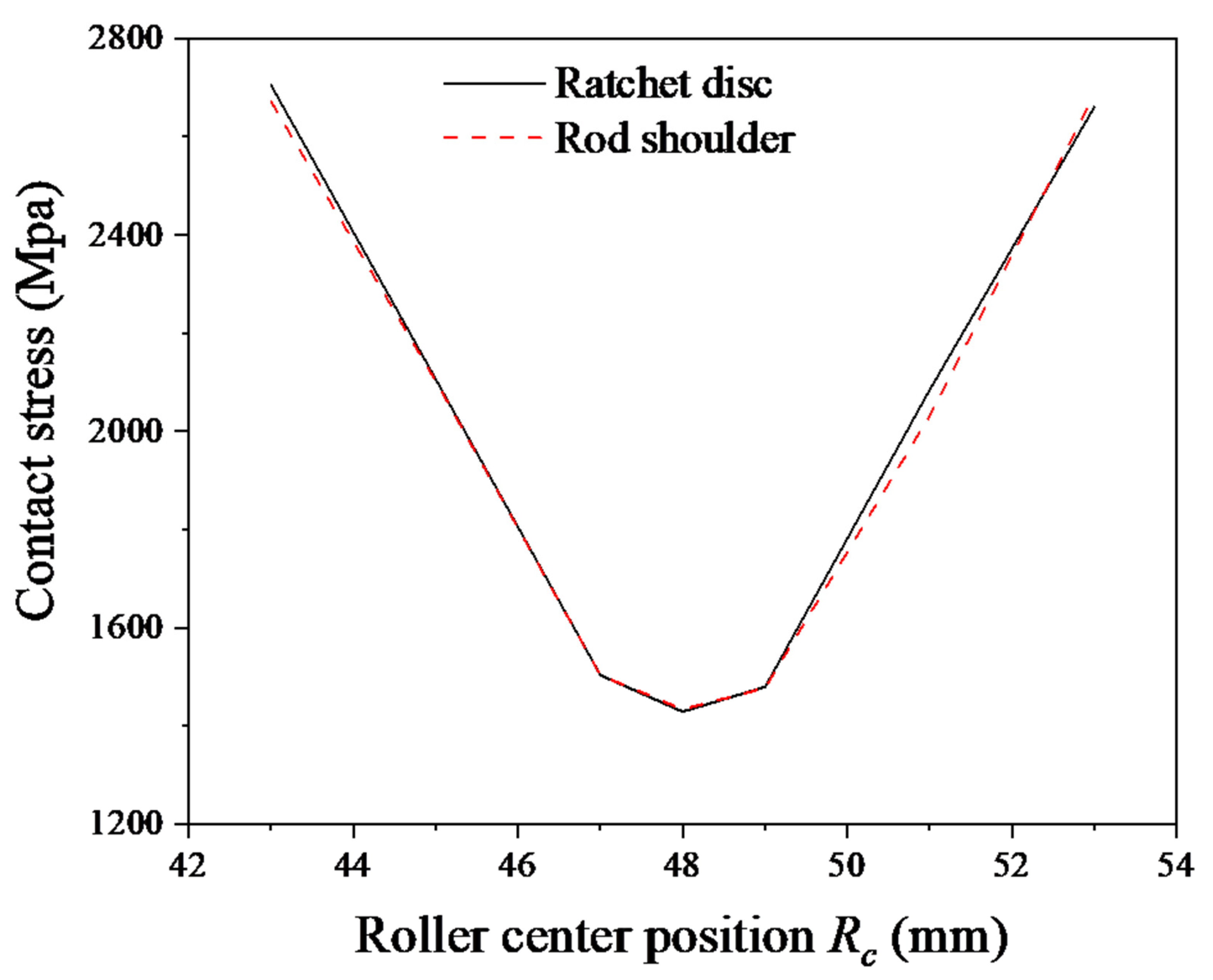
Such deformation variations in the no-back brake components significantly affect the contact state. Figure 20 and Figure 21 show the contact stress contours between the rollers and the ratchet disc/rod shoulder under different roller centre position. Figure 22 shows the variation in the maximum value of roller contact stress with the load centre position. It can be seen that when the roller centre position Rc is small, the deformation of the ratchet wheel is greater than that of the rod shoulder. At this time, the contact between the rollers and the ratchet disc/rod shoulder is mainly concentrated on the outer circumference side. As Rc increases, the maximum contact stress gradually decreases. When the deformations of the ratchet disc and the rod shoulder are equal (approximately 0.024 mm), the roller contact stress distribution is most uniform, and the contact stress reaches its minimum value (approximately 1430 MPa). Compared with the initial value, the optimized contact stress value has significantly decreased by 38.9%. At this point, Rc is approximately 48 mm, which is slightly offset from the load centre of 49 mm. When Rc continues to increase, the deformation of the ratchet disc becomes less than that of the rod shoulder, the roller contact area gradually expands towards the inner side, and the contact stress begins to increase.
From the above research results, it can be seen that there is an optimal Rc value that minimizes the roller contact stress. This optimal value can be obtained by a “deformation balance” method, i.e., to balance the deformations of the ratchet disc and the rod shoulder.

6. Conclusions

In this study, systematic theoretical and experimental research was conducted on SRTB applied in no-back brakes, focusing on torque and contact characteristics. The key findings and innovative conclusions are summarized as follows:
(1)
The resistance torque of the SRTB is primarily dominated by the roller skew angle and centre position, increasing monotonically with both parameters. Experimental validation confirms that the measured friction coefficient of the SRTB is approximately 0.12, with a variation in less than 0.3% between forward and reverse rotations, indicating negligible directional dependence. Additionally, the friction coefficient decreases by approximately 4% when the rotational speed increases from 67.5 rpm to 112.5 rpm, verifying the stability of the bearing’s performance under low-speed conditions and the effectiveness of the proposed design.
(2)
Tangent arc profiling effectively optimizes the roller contact stress distribution. The roller contact stress first decreases sharply and then increases gradually with increasing crown drop, and the optimal crown drop value first decreases and then increases with increasing straight segment length. Quantitative analysis shows that the optimal parameters for minimizing contact stress are 9 μm (crown drop) and 4 mm (straight segment length).
(3)
The bending deformation and contact stress concentration of the SRTB and no-back brake caused by asymmetric loads under actual working conditions are investigated. A method for optimizing the roller centre position based on the principle of “deformation balance” is put forward, that is, to balance the deformations of the ratchet disc and the rod shoulder. The optimal position of the roller is determined to be 48 mm in this paper, which is slightly offset from the load centre. The maximum contact stress of the roller is reduced from 2339.6 MPa to 1430 MPa, representing a decrease of 38.9%. This method provides a key reference for the optimal design of the no-back brake.

Author Contributions

Conceptualization, T.R., S.L. and M.F.; methodology, T.R. and M.F.; software, T.R. and Z.C.; validation, Z.C. and M.F.; formal analysis, Z.C. and M.F.; investigation, T.R., S.L. and Z.C.; resources, S.L. and M.F.; data curation, T.R. and Z.C.; writing—original draft preparation, T.R. and Z.C.; writing—review and editing, S.L. and M.F.; visualization, T.R. and Z.C.; supervision, S.L. and M.F.; project administration, S.L. and M.F.; funding acquisition, S.L. and M.F. All authors have read and agreed to the published version of the manuscript.

Funding

This research was funded by the Shanghai’s “Open Bidding for Selecting the Best Candidates” Project (grant number: YDZX20223100004003).

Data Availability Statement

The data presented in this study are available on reasonable request from the corresponding author.

Conflicts of Interest

The authors declare no conflicts of interest.

Nomenclature

BrThickness of rotating disc
BsThickness of support disc
cCrown drop of roller
DOuter diameter of rotating/support disc
dInner diameter of rotating/support disc
EYoung’s modulus
FbAxial force exerted by no-back brake on ball screw
FgAerodynamic force along ball screw
LRoller length
LwEffective length of roller
lStraight segment length of roller
NRotational speed
RNominal roller radius
RaSurface arithmetic mean deviation
RcRoller centre position
RtCorrection arc radius of roller
rRoller fillet radius
TbResistance torque of SRTB/no-back brake
TdDriving torque of HSTA
TgAerodynamic torque around ball screw
WExternal load on roller
βSkew angle of roller
σContact stress
σavgAverage contact stress
σmaxMaximum contact stress
σRMaximum contact stress (roller-rotating disc)
σSMaximum contact stress (roller-support disc)
θCircumferential position

References

  1. De Alwis, A.; Ward, R.; Schuyler Hinman, W. Numerical Analysis of the Performance and Drag Re-duction Mechanisms of Outboard Horizontal Stabilizers. Aerosp. Sci. Technol. 2025, 158, 109892. [Google Scholar] [CrossRef] [Scilit]
  2. Xu, S.; Fang, G.; Zhao, L.; Ge, Y.; Zhang, J. Aerodynamic and Aerostatic Performance of a Long-Span Bridge with Wide Single Box Girder Installed with Vertical and Horizontal Stabilizers. J. Struct. Eng. 2023, 149, 4023106. [Google Scholar] [CrossRef] [Scilit]
  3. Qiao, S.; Hao, Y.; Quan, L.; Ge, L.; Xia, L. Design and Analysis of a Novel Impact- Resistant Electro-Mechanical Actuator with Disc Spring Compression and Hydraulic Buffering Mechanism. IEEE/ASME Trans. Mechatron. 2024, 29, 2138–2149. [Google Scholar] [CrossRef] [Scilit]
  4. Kim, D.-H.; Choi, S.B. Design of Ball-Ramp Dual Clutch Transmission to Reduce Uncertainties in Clutch Actuator and Tie-up Effect. Mech. Mach. Theory 2022, 176, 104982. [Google Scholar] [CrossRef] [Scilit]
  5. Zhang, W.; Fu, J.; Maré, J.-C.; Ma, H.; Xia, T.; Fu, Y.; Zhao, J. Investigations on MBSE Modelling and Dynamic Performance Assessment of an Electrical Trimmable Horizontal Stabilizer Actuator. Chin. J. Aeronaut. 2023, 36, 417–433. [Google Scholar] [CrossRef] [Scilit]
  6. Wei, Y.; Bao, H.; Li, Q.; Huang, Z. Thermal-Fluid Coupling Analysis of Aviation Wet Friction Clutch with Wavy Separation Spring. Ind. Lubr. Tribol. 2025, 77, 370–379. [Google Scholar] [CrossRef] [Scilit]
  7. Lai, J.; Guan, W.; Luo, G.; Chao, S. Design of Rectangular Cross-Section Spring Anti-Reverse Device for A Certain Type of Aviation. J. Beijing Univ. Aeronaut. Astronaut. 2024, 50, 1868–1876. (In Chinese) [Google Scholar] [CrossRef]
  8. Liu, X.; Bai, X.; Cui, J.; Yang, P. Thermal Elastohydrodynamic Lubrication Analysis for Tilted and Skewed Rollers in Cylindrical Roller Bearings. Proc. Inst. Mech. Eng. Part J J. Eng. Tribol. 2016, 230, 428–441. [Google Scholar] [CrossRef] [Scilit]
  9. Majdoub, F.; Saunier, L.; Sidoroff-Coicaud, C.; Mevel, B. Experimental and Numerical Roller Skew in Tapered Roller Bearings. Tribol. Int. 2020, 145, 106142. [Google Scholar] [CrossRef] [Scilit]
  10. Yang, Y.; Wang, J.; Wang, M.; Wen, B. Dynamic Modeling and Behavior of Cylindrical Roller Bearings Considering Roller Skew and the Influence of Eccentric Load. Lubricants 2024, 12, 317. [Google Scholar] [CrossRef] [Scilit]
  11. Liu, K.; Niu, S.; Liu, Z.; Ruan, Z.; Wei, H. Research on the Curved Surface of Bearing Clutch. J. Xi’an Univ. Technol. 1998, 14, 6–12. (In Chinese) [Google Scholar] [CrossRef]
  12. Feng, M.; Ono, K.; Mimura, K. Mixed EHL analysis of the variable torque slipping clutch with skewed rollers. J. Tribol. 2003, 125, 756–769. [Google Scholar] [CrossRef] [Scilit]
  13. Duan, Q.; Yin, Y.; Liu, Z. The Stress Analysis for Roller Bearing Clutch Based on ANSYS. Mod. Manuf. Eng. 2008, 1, 84–86. (In Chinese) [Google Scholar] [CrossRef]
  14. Feng, M.; Ono, K.; Mimura, K. Stress Analysis of a New Disk-Type Variable Torque Slipping Clutch with Skewed Rollers. JSME Int. J. Ser. C Mech. Syst. Mach. Elem. Manuf. 2003, 46, 1509–1522. [Google Scholar] [CrossRef] [Scilit]
  15. Kountanya, R.; Jagdale, V. Frictionless Elastic Contact of Crowned Roller: Approximate Analytical Calculation of Compliance and Contact Area. Proc. Inst. Mech. Eng. Part J J. Eng. Tribol. 2015, 229, 1206–1213. [Google Scholar] [CrossRef] [Scilit]
  16. ISO 76:2006; Rolling Bearings—Static Load Ratings. International Organization for Standardization: Geneva, Switzerland, 2006.
Figure 1. Schematic diagram of the HSTA.
Machines 14 00132 g001
Figure 2. Schematic diagram of the no-back brake. (a) Overall structure; (b) Ratchet and pawl.
Machines 14 00132 g002
Figure 3. Structure of the SRTB.
Machines 14 00132 g003
Figure 4. Motion of the SRTB.
Machines 14 00132 g004
Figure 5. Roller of the SRTB.
Machines 14 00132 g005
Figure 6. Variation in resistance torque with bearing parameters. (a) Skew angle; (b) Roller centre position.
Machines 14 00132 g006
Figure 7. Test platform. (a) Schematic diagram; (b) Physical picture.
Machines 14 00132 g007
Figure 8. Tested SRTB.
Machines 14 00132 g008
Figure 9. Experimental resistance torque of the SRTB with axial load. (a) Forward rotation; (b) Reverse rotation.
Machines 14 00132 g009
Figure 11. Mesh of SRTB.
Machines 14 00132 g011
Figure 12. Variation in roller contact stress with crown drop. (a) Rotating disc; (b) Support disc.
Machines 14 00132 g012
Figure 13. Contour of contact stress between roller and rotating disc under different crown drops (l = 4 mm). (a) c = 7 μm; (b) c = 8 μm; (c) c = 9 μm; (d) c = 10 μm; (e) c = 11 μm.
Machines 14 00132 g013
Figure 14. Axial deformation of the bearing (l = 4 mm, c = 9 μm).
Machines 14 00132 g014
Figure 15. Analysis model of the no-back brake component.
Machines 14 00132 g015
Figure 16. Axial deformation of the no-back brake component.
Machines 14 00132 g016
Figure 17. Contour of roller contact stress. (a) Ratchet disc; (b) Rod shoulder.
Machines 14 00132 g017
Figure 18. Axial deformation of the no-back brake component. (a) Rc = 43 mm, β = 32.27°; (b) Rc = 45 mm, β = 30.67°; (c) Rc = 48 mm, β = 28.57°; (d) Rc = 49 mm, β = 27.94°; (e) Rc = 51 mm, β = 26.75°; (f) Rc = 53 mm, β = 25.67°.
Machines 14 00132 g018
Figure 19. Axial deformation contours of the no-back brake component.
Machines 14 00132 g019
Figure 20. Contour of contact stress between roller and ratchet disc. (a) Rc = 43 mm, β = 32.27 °; (b) Rc = 45 mm, β = 30.67 °; (c) Rc = 48 mm, β = 28.57 °; (d) Rc = 51 mm, β = 26.75°; (e) Rc = 53 mm, β = 25.67°.
Machines 14 00132 g020
Figure 21. Contour of contact stress between roller and rod shoulder. (a) Rc = 43 mm, β = 32.27°; (b) Rc = 45 mm, β = 30.67°; (c) Rc = 48 mm, β = 28.57°; (d) Rc = 51 mm, β = 26.75°; (e) Rc = 53 mm, β = 25.67°.
Machines 14 00132 g021
Figure 22. Variation in roller contact stress with load centre position.
Machines 14 00132 g022
Table 1. Parameters of the SRTB.
ParameterValue
Outer diameter of rotating disc and support disc, D, mm115
Inner diameter of rotating disc and support disc, d, mm72
Thickness of rotating disc, Br, mm6
Thickness of support disc, Bs, mm10
Roller radius, R, mm4.5
Roller length, L, mm12
Roller fillet, r, mm1.0
Number of rollers20
skew angle, β, °31.5
Roller centre position, Rc, mm44.25
Poisson’s ratio0.3
Young’s modulus, E, GPa208
Table 2. Influence of contact area mesh size on calculation results.
Element Size/mmNode NumberContact Stress σR/MpaContact Stress σS/Mpa
0.21244601042.91066
0.120497014051395
0.072781901423.11453.6
0.063405401448.21466.5
0.054358301473.11499.6
0.046229801502.51512.5
Disclaimer/Publisher’s Note: The statements, opinions and data contained in all publications are solely those of the individual author(s) and contributor(s) and not of MDPI and/or the editor(s). MDPI and/or the editor(s) disclaim responsibility for any injury to people or property resulting from any ideas, methods, instructions or products referred to in the content.