Abstract
To address the issue of uneven load and premature failure in ball–column composite bearings caused by ring deformation, this study develops a mechanical analysis model, considering ring deformation based on flexible ring theory and rolling bearing design. It systematically examines radial deflection of the ring and how key parameters affect load distribution and stress. The results demonstrate that the elastic deformation of the collar redistributes the load, reduces the roller column’s load-carrying efficiency, and disrupts the optimal load distribution mode. Increasing the number of loaded rolling elements significantly improves the load uniformity, reduces the peak contact stress, and enhances the overall load-carrying performance. By optimizing the clearance matching across three bearings rows, a load-adaptive gradient bearing mechanism is realized by dynamically transferring, 70–90% of the heavy-load optimal distribution. These findings address the domestic research gaps and offer theoretical support for the performance prediction and optimal design of integrated ball–column composite bearings.
1. Introduction
Ball–column composite bearings combine the advantages of ball and cylindrical roller bearings. By integrating two rows of angular contact ball bearings with one row of cylindrical roller bearings, they efficiently share radial and axial loads, offering strong load-carrying capacity, compact structure, and smooth operation []. The outer ring of the three-row bearing adopts a one-piece arc structure that provides an adaptive self-aligning function while bearing high loads. It compensates for small angular deviations induced by dynamic impacts, structural elastic deformation, or assembly errors in environments such as vehicle-mounted radar and airborne warning and control system radomes. This design reduces the risk of hysteresis from high stress concentration and enhances the bearing’s rotational accuracy and service life under variable loading conditions, including vibration and shock. Particularly in airborne and vehicle-mounted radar applications, which demand high rotational stability and reliability, the design achieves a careful balance-centering function and structural rigidity. This balance ensures sufficient load-bearing capacity and effectively inhibits early fatigue failure. However, the curved outer ring structure reduces the collar’s overall stiffness. Under combined radial force, axial, and torque loads, the bearing collar produces a certain amount of deformation, thereby affecting the composite bearing clearance distribution. Unreasonable clearance exacerbates stress concentration, increasing bearing hysteresis, impairing machine rotary accuracy, and in severe cases, causing premature fatigue failure. Therefore, it is necessary to examine the bearing characteristics of ball–column composite bearings to enhance their load-bearing performance, reliability, and rotary accuracy.
Stribeck [] investigated the elastic–plastic problem between rolling element and raceway contact through experiments and derived a relationship between the maximum contact load and radial load. However, the study did not address the elastic–plastic problem under combined load. Based on the Hertzian contact theory, Zupan et al. [] examined the deformation coordination relationship between the balls and raceway and analyzed the impact of a rigid support structure on load distribution. Moreover, Kania et al. [] employed finite element analysis to examine how the number of rolling elements affects the contact stress and load distribution of the bearing. Smolnicki et al. [] explored the effect of flexible support structure and uneven ball distribution on the load-carrying capacity of four-point contact ball bearings, revealing their significant effect on load distribution and load-carrying capacity. Alain et al. [] used a unidirectionally loaded nonlinear spring model to analyze load distribution in a four-point contact rotary table bearing; however, the study did not consider the effect of nonlinear spring dynamic stiffness. Gabriel et al. [] developed a mathematical model for flexible collar deformation based on Roark’s formula, considering the effect of elastic deformation on the load distribution. Additionally, Aguirrebeitia et al. [] established a force balance equation for bearings under axial load and tilting moment and proposed a method for calculating the ultimate load of rotary table bearings; however, the effect of radial load was not considered. P. Göncz et al. [,] developed a finite element analysis model for bearings using a nonlinear spring instead of a roller. The study analyzed raceway contact stresses, calculated fatigue life, and proposed a method for determining the load-carrying capacity of three rows of roller rotary table bearings. Noel et al. [] proposed a method for calculating the stiffness matrix of angular contact ball bearings at high rotational speeds, improving the accuracy of results. In addition, Tong et al. [] optimized the DeMul model and developed a five-degree-of-freedom hydrostatic tapered roller model to analyze the effect of radial force and moment, though the model did not consider the influence of axial force. Zhang et al. [] analyzed the static and dynamic stiffness of elastic composite cylindrical roller bearings, using the finite element method, and validated the theoretical results experimentally. Korolev et al. [] explored the load distribution in angular contact ball bearings under combined load and revealed the relationship between contact angle and load distribution. Furthermore, Li et al. [] developed a force equilibrium model for a double-row four-point contact ball wind turbine pitch rotor shaft bearing. Using coordinate transformations in a Cartesian system, the study calculated the elastic deformation of the rolling body and raceway. The research revealed that moderate negative clearance, decreased groove curvature radius, and increased contact angle positively affect load-carrying capacity. Han et al. [] considered the effects of temperature and clearance and established a cylindrical roller bearing finite element model. The study further analyzed the characteristics of load distribution, shaft deformation, contact stress, and collar stiffness. Rather than using the ball calculation method, Li et al. [] proposed a nonlinear spring for the finite element analysis model of large wind power bearings, effectively reducing simulation complexity and improving computational efficiency; however, this method does not consider the effect of spring dynamic stiffness. Iker et al. [] established a semi-analytical mechanical model of a four-point contact rotary disc bearing to analyze the effects of the bearing preload, manufacturing error, and flexible collar deformation on load distribution. Furthermore, Fang et al. [] proposed new initial assumptions to establish a five-degree-of-freedom hydrostatic ball bearing model and investigated the effect of rotational speed on bearing stiffness under various load conditions. Hao et al. [] investigated the time-varying stiffness of cylindrical roller bearings under different lubricating oils, revealing the relationship between the temperature and the stiffness. Li et al. [] developed a hydrostatic stiffness model for ball bearings considering elasto-fluid lubrication and centrifugal force, and analyzed how various factors affect bearing characteristics. The proposed static stiffness model further considers the effects of temperature rise and centrifugal force. Moreover, Rivera et al. [] developed a quasi-static X-ACBB (crossed-axle, angular contact ball bearing) model under five-degree-of-freedom (5-DOF) loading, demonstrating stiffness transitions from two- to three-point contact under axial loads and identifying critical geometric factors affecting bearing performance. Sinha et al. [] introduced a mathematical solution for load distribution in variable-clearance ball bearings with elliptical outer raceways, enhancing the analytical framework for such configurations. Hou et al. [] proposed a strain-response-based method to measure load distribution in cylindrical roller bearings, supported by a specially designed experimental setup. Xu et al. [] presented a computational method for radial time-varying stiffness in cylindrical roller bearings, accounting for flexible collar and raceway defects. Their findings revealed that defect area expansion amplifies stiffness fluctuations, though the influence of axial force and moment remained unaddressed. Wang et al. [] formulated a hydrostatic contact model for ball bearings incorporating inner ring offset, streamlining the iterative initial value selection to boost computational efficiency. Chen et al. [] established a dynamic aerostatic bearing model to evaluate the effects of imbalance factors and manufacturing errors on static and dynamic characteristics. Experimental results validated the model’s accuracy, offering a theoretical foundation for spindle rotational error prediction and precision control. Zhu et al. [] introduced a dynamic model for magnetic suspension system protective bearings. Through simulations and experiments, they analyzed structural parameter impacts and derived optimized configurations for enhanced impact resistance. Zeng et al. [] proposed a quasi-static ring misalignment model for shaft bearing systems, incorporating assembly deviations, multi-datum geometric tolerances, and dynamic loads, with experimental validation confirming its robustness. In summary, scholars at home and abroad have extensively studied the mechanical properties of traditional ball bearings and roller bearings, yielding significant insights. However, studies on combined bearings and integrated ball–column composite bearings remain limited. In practice, ball–column composite bearings must effectively distribute load across all columns to avoid the early failure of single-column bearings owing to uneven loads, which affects service life and overall operational stability.
This study establishes a comprehensive mechanical analysis model for ball–column composite bearings based on flexible collar theory. Following the fundamental model development, the research systematically examines the adaptive gradient loading mechanism’s behavior under complex operating conditions, with subsequent analyses focusing on critical performance factors including structural deformations, rolling element configurations, and raceway geometry parameters. The findings advance the understanding of dynamic load distribution mechanisms in integrated bearing systems, bridging important research gaps while establishing a reliable theoretical framework for performance evaluation and design optimization of such composite bearings.
2. Ball–Column Composite Bearing Modeling
2.1. Geometric Modeling
As shown in Figure 1, the ball–column composite bearing structure integrates two rows of angular contact ball bearings and one row of cylindrical roller bearings. The angular contact ball bearings primarily handle axial force Fa, while cylindrical roller bearings primarily handle radial force Fr. These three bearing rows share a single outer ring, with the inner ring comprising three separate components. In this study, the bearing employed is primarily used in applications requiring high load-carrying capacity and high rotary accuracy, such as cranes, engineering machinery joints, and rolling mills. To satisfy the requirements, the design adopts a curved outer ring structure, providing the bearings with an adaptive self-aligning function, which significantly improves its adaptability in complex operating conditions.
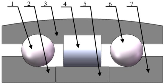
Figure 1.
Schematic structure of ball–column composite bearing. 1: First-row angular contact ball bearings; 2: inner ring 1; 3: outer ring; 4: second-row cylindrical roller bearings; 5: inner ring 2; 6: third-row angular contact ball bearings; 7: inner ring 3.
2.2. Mechanical Analysis Model of Ball–Column Composite Bearing
To analyze ball–column composite bearings under the external load, a global and local coordinate system is established with the center of each column bearing and the relative displacement of the inner ring with respect to the collar center as the origin (Figure 2). Let represent the external total load on the bearing’s inner circle, and denote the external load acting on the inner ring of each column bearing load.
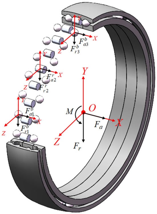
Figure 2.
Coordinate system of ball–column composite bearing.
In this study, only the deformation in the coordinate plane XOY is analyzed to construct the overall force balance equation of the ball–column composite bearing:
In Equations (1)–(3), , , and are the applied external radial force, axial force, and torque, respectively. , , and represent the radial force each bearing row to withstand. , , and denote the axial force each bearings row withstand. and indicate the distances between the cross-section centers of the three rows of the rolling body.
2.3. Load-Induced Deformation Analysis of Multi-Row Bearings Based on Compliant Raceway Theory
In this context, raceway deformation analysis is presented only for the XOY plane; however, deformation in other planes can also be analyzed in the same manner. When subjected to radial force Fr, axial force Fa, and tilting moment M under loaded conditions, the ball–column composite bearing-loaded conditions experience deformation in its three columns of the rolling body, influenced by their positional relationship, as shown in Figure 3. indicates that the relative radial displacement of the inner and outer rings after the bearing is loaded; indicates that the relative axial displacement of the inner and outer rings after the bearing is loaded; and shows that the tilting angle of the inner ring after the bearing is loaded. j and represent the number and azimuthal angle of each rolling element.
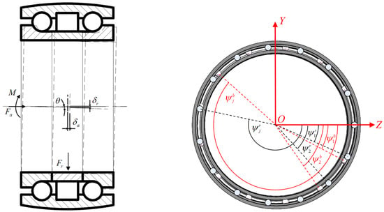
Figure 3.
Deformation diagram and azimuthal orientation schematic of the ball–column composite bearing under load.
2.3.1. Micro-Geometry Alteration Analysis of Outer Ring Contour in Ball–Column Bearings
For the outer ring and housing contact deformation analyses, the internal structure of the entire bearing is used to simplify the analysis, as illustrated in Figure 4. The establishment of the outer ring and the housing of the local equilibrium equation is given by:
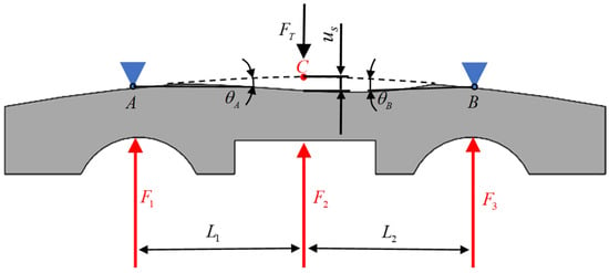
Figure 4.
Schematic diagram of contact deformation between the outer ring’s circular arc surface and the bearing housing.
The bearing ring’s deformation can be modeled as the flexural deflection of a simply supported beam with two reaction points. As shown in Figure 4, the outer ring is parallel to the bearing centers of the first- and third-row bearings, with Points A and B defined as the fixed support locations. Considering Point A as the reference origin, the bending moment equations are established for segments AC and BC (where C represents the load application point or the location of maximum deflection). Solving these equations yields the deflection curve and partial rotation angle at the end cross-section, as follows:
In Equations (4)–(6), , , and represent the external load extension in the normal direction to the outer ring of the three raceways of the force. and represent the columns of the bearing center cross-section of the relative distance. denotes the seat of the reaction force. denotes contact deformation of the outer ring generated by the external load extension in the normal direction. x denotes the lateral position coordinate of the beam, used to describe the distance from the calculation point to the reference origin. E represents the elastic modulus of the bearing material and I corresponds to the cross-sectional moment of inertia
2.3.2. Flexural Deformation Analysis of Compliant Raceway in Rolling Bearings
The outer ring is designed with an arc-shaped self-aligning structure to satisfy the functional requirements of a combined ball-and-roller bearing. Under external loads, this self-aligning feature causes the bearing ring to deviate from the ideal circular geometry during operation. To analyze the influence of radial deflection at arbitrary angular positions on the contact deformation, Figure 5 illustrates a schematic representation of how the bending deformation of the bearing ring affects the contact deformation in a radial contact bearing under zero radial clearance conditions.
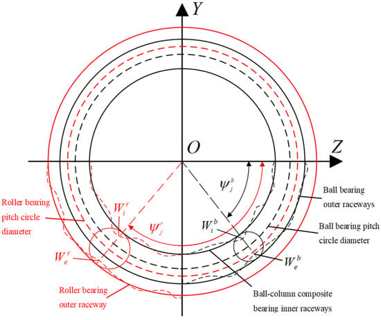
Figure 5.
Effect of bending deformation on rolling element contact behavior.
Based on the thin-walled ring planar bending theory, the differential equation describing the radial deflection of the bearing ring at an arbitrary angular position under plane force system loading is given as follows:
The general solution obtained by integrating the differential equation represents the radial deflection of the bearing ring at position , which can be expressed as:
Style:
In Equations (7)–(10), represents the radial deflections of the inner and outer raceways in the ball or roller bearing assemblies. denotes the angular position of the jth rolling element row. The bending moment acting on the raceway cross-section is expressed as . defines the angular offset between the phase angle at the nth load application point and the reference position, whereas indicates the radial load sustained by an individual rolling element. The applied moment load is designated as .
2.3.3. Load-Deformation Analysis of Ball Row
Figure 6 and Figure 7 depict the relative displacement between the inner and outer rings of an angular contact ball bearing under combined loading, along with the relative positions of the jth ball center and the raceway curvature centers of inner and outer rings. The bearing raceways remain unloaded with no external load. Owing to the arcuate structure of the outer ring, its contact area with the housing is limited. Under heavy combined loading, deformation occurs in the thin-walled outer ring, leading to a change in its position. Specifically, the outer ring undergoes an angular displacement and a radial displacement , altering the position of its raceway curvature center. Simultaneously, the inner ring experiences an angular displacement , radial displacement , and axial displacement in the loading direction, shifting its raceway curvature center from position to . Consequently, the ball center moves from position to and the contact angles between the ball and inner and outer raceways change from the initial preload angles to and after loading.
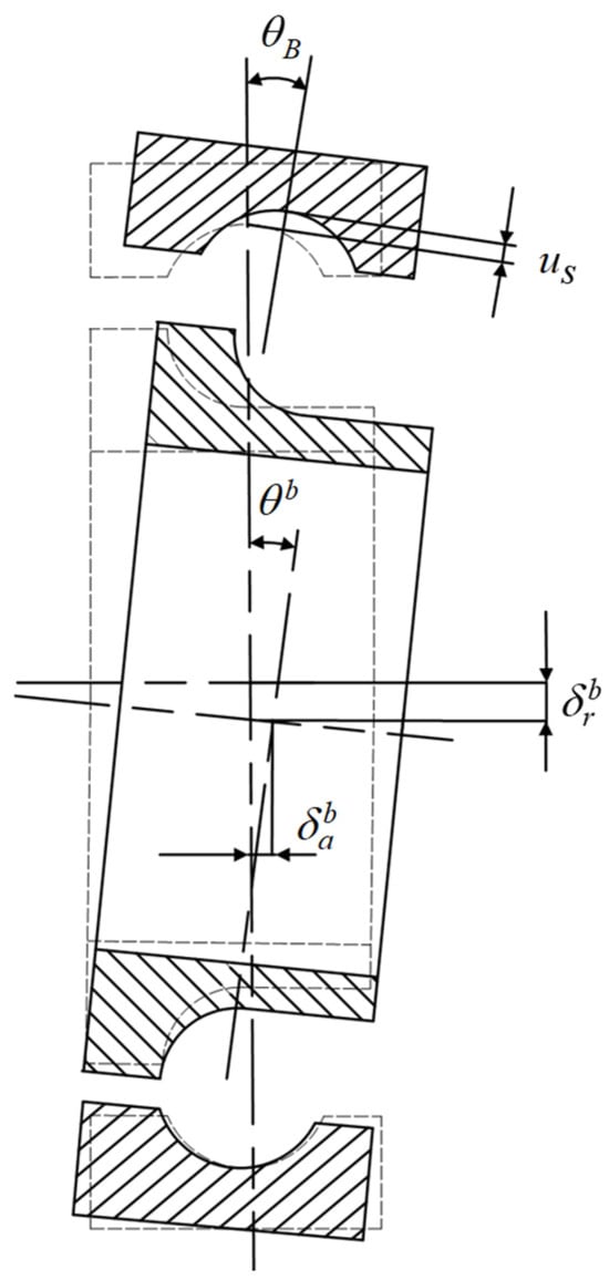
Figure 6.
Relative displacement of inner and outer rings under combined loading.
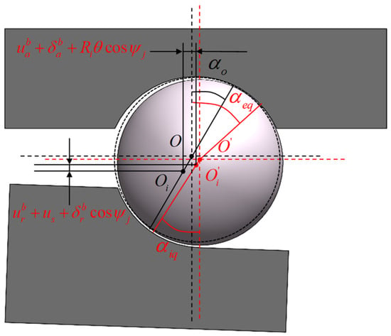
Figure 7.
Relative position of the center of the jth ball to the center of curvature of the inner and outer grooves.
As shown in Figure 7, the total contact elastic deformation between the rolling element and the inner and outer rings at any position after loading the inner ring of the bearing under a rigid collar is expressed as follows:
Style:
The contact angle of each ball with the inner and outer grooves given by:
The total contact elastic deformation of the rolling body with inner and outer rings at any position under the flexible collar is calculated based on Equations (8) and (11), as follows:
The ball and raceway contact load is given by []:
The force balance equation for the localized inner ring of the angular contact ball bearing is constructed as follows:
In Equations (11)–(18), A represents the distance between the center of curvature of the inner and outer groove before the bearing load, Z denotes the number of balls, and denotes the initial contact angle of the balls. represents the radius of the center of curvature of the inner ring’s groove, denotes the position angle of the balls, and denotes the axial clearance of the balls. represents the radial clearance of the balls, represents the angular displacement of the inner ring due to load, represents the radial displacement, and represents the axial displacement of the inner ring due to load. represents the load deformation coefficient of the ball, represents the angular displacement of the inner ring of the previous row of bearings, denotes the diameter of the pitch circle of the bearing and denotes the angular displacement of the outer ring of the bearing due to ring deformation, represents the amount of radial displacement of the outer ring due to collar deformation, depicts the amount of total contact elastic deformation between the ball and the inner and outer rings under the rigid collar, and denotes the total contact elastic deformation between the ball and the inner and outer rings under the flexible collar.
2.3.4. Load Deformation Analysis of Roller Row
As shown in Figure 8, the roller column bearings influenced by the ball bearings experience complex load behavior due to the deflection angle of the bearing collar. To address this, the “slicing method” is analyzed and calculated on the cylindrical roller load. As shown in Figure 9, the joint load cylindrical roller column roller and raceway contact deformation consists of two aspects: (1) deformation produced by the jth roller under external load and (2) reduction of the convexity of the extended roller bus profile on the kth slicing unit . The figure details the components of the elastic deformation of the rollers, where the profile protrusion’s amount is negatively deformed for the kth slicing unit. This unit remains in the no-contact state until the deformation produced counteracts the gap between the rollers and the raceway.
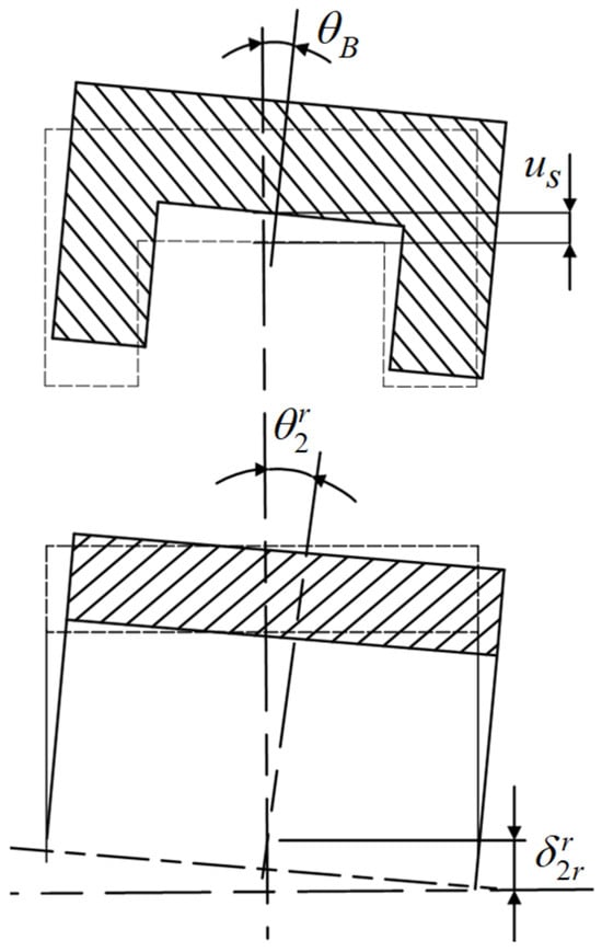
Figure 8.
Schematic diagram of tilting of cylindrical roller column bearing under combined load.
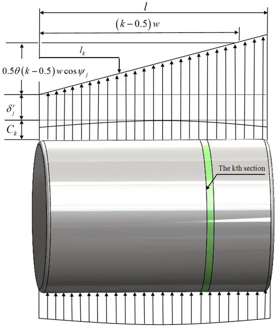
Figure 9.
Schematic diagram of composition of deformation components of cylindrical roller.
As shown in Figure 9, a roller with an azimuthal angle of has an effective deflection angle of . Assuming that the load is symmetric in [0–180°], it takes a positive value in the range of [0–90°] and a negative value in the range of [90°–180°].
The kth slice unit of the jth roller is deformed in contact with the raceway as follows:
The joint Equations (8) and (19) calculate the contact elastic deformation of a single slice of the rolling body at any position under the flexible collar in contact with the inner and outer rings as follows:
For each roller, there are k slices, each with a width of is . According to the Hertzian contact theory, the load of each slice is calculated as follows:
By combining Equations (19) and (21), the total load of the jth roller is expressed as:
The localized inner ring force balance equation for cylindrical roller bearings is constructed as:
In Equations (19)–(25), represents the amount of kth slicing unit’s deformation of the jth roller in contact with the raceway, represents the thickness of the roller slicing, denotes the amount of angular displacement generated by the inner ring of the load bearing, and represents the amount of radial displacement generated by the inner ring of the load bearing. denotes the amount of angular displacement occurring in the outer ring of the bearing due to the deformation of the collar, is the amount of angular displacement of the first-row angular contact ball bearing’s inner ring, and denotes the radial displacement of the bearings’ outer ring due to the collar deformation.
2.4. Flowchart of Numerical Calculations
The numerical solution methodology proposed in this study, which accounts for the raceway deformation effects, follows the computational workflow as illustrated in Figure 10. First, the global force equilibrium equations for the ball-roller compound bearing system are established to determine load distributions on each bearing row’s inner ring under external loading. Subsequently, based on the axial load direction, three-dimensional force and moment equilibrium equations are sequentially formulated for each bearing row, iteratively transferring displacement variables from preceding rows downstream. A cyclic solution algorithm is implemented until convergence. Finally, outer ring deformation (radial displacement and tilt angle) is computed via the raceway-to-housing force equilibrium using the obtained contact loads, followed by feedback iterations to update the three-row bearing equilibrium system.
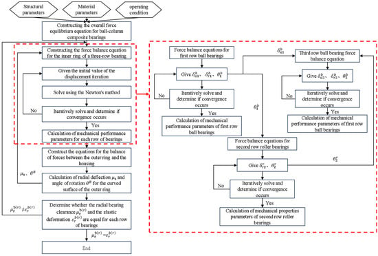
Figure 10.
Flowchart of numerical calculation.
The proposed mechanical analysis model of ball–column composite bearing presents notable advantages compared to FEM in terms of computational efficiency and implementation simplicity. Unlike conventional FEM requiring complex meshing procedures, this analytical approach relies on direct mechanical formulations to achieve efficient solutions while maintaining satisfactory accuracy in both static and dynamic analyses. The methodology proves particularly advantageous for bearing design optimization and system-level vibration studies, where multiple parameter variations would render conventional FEM computations prohibitively time-consuming.
3. Numerical Case Studies and Performance Evaluation
Table 1 presents the main structural parameters of the bearings. Ball–column composite bearings often operate at low speeds and under heavy and composite loads. This results in flexible collar elastic deformation that can not be ignored, directly affecting the bearings’ service and slewing accuracy. Combined with the typical conditions shown in Table 2, this study analyzes the radial deflection of the ring. This study examines the influence of raceway deformation on the self-adaptive gradient load-sharing mechanism in ball-roller hybrid bearings. Furthermore, based on these deformation effects, critical structural parameters, including the roller count, contact angle, and radial clearance—are analyzed to determine their impact on the load-carrying characteristics of the bearing.

Table 1.
Structure parameters of ball–column composite bearing.

Table 2.
Operating conditions of ball–column composite bearings.
3.1. Comparative Validation of Results
To validate the adaptive gradient load-sharing mechanism of the hybrid bearing, a comparative analysis was performed between the computational results of the proposed model and Romax 2018 commercial software simulations. The analysis used the structural parameters from Table 1 and operating conditions detailed in Table 2. As Romax lacks dedicated hybrid bearing modules, a simulated model was constructed using combined single-row bearing configurations (Figure 11). The comparative results under various operating (as shown in Figure 12) demonstrate a close agreement between the proposed model and Romax simulation outputs. This verifies the model’s effectiveness in characterizing bearing load distribution behavior and highlights the need for specialized hybrid bearing analysis tools, which conventional commercial software lacks.
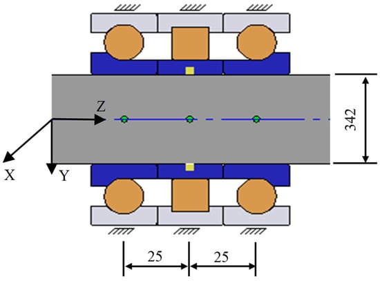
Figure 11.
Romax combination bearing simulation model.
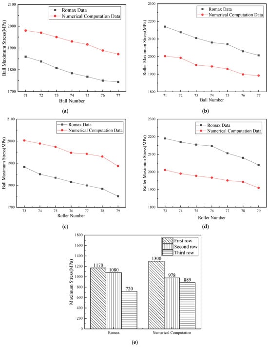
Figure 12.
Comparison of calculation results. (a) Impact of the number of balls on maximum contact stress of the ball bearings under Condition 1. (b) Impact of the number of balls on maximum contact stress of the roller bearing under Condition 1. (c) Impact of roller quantity on maximum contact stress of the ball bearings under Condition 1. (d) Impact of roller quantity on maximum contact stress of the ball bearings under Condition 1. (e) Condition 2, 78 rollers, 74 balls, and contact angle of 40°.
The comparative test results exhibited good agreement in load transfer trends between the proposed computational model and Romax commercial software simulations. However, discrepancies were observed between the two calculation results owing to the inherent limitations in Romax’s modeling approach, including system default bearing types, fixed internal dimensional parameters, and non-flexible raceway assumptions. Furthermore, owing to the lack of dedicated hybrid bearing configurations in Romax, the simulation substituted structurally similar single-row bearing. This inevitably introduced additional computational deviations by failing to replicate the actual ball-roller composite bearing geometry and its unique load-sharing characteristics [].
3.2. Analysis of Radial Deflection Effects on the Outer Ring Curved Surface
As illustrated in Figure 13 and Figure 14, under Condition 1 parameters (74 balls, 78 cylindrical rollers, 0 clearance, and a raceway cross-section rotation angle of 0°), increasing the outer ring’s radial deflection detrimentally redistributes load within the three-row bearing system. The original auxiliary ball bearing row becomes overloaded (the loaded ball count increased from 19 to 27 in the third row), whereas the load capacity of the roller bearing is compromised (the loaded roller count decreased from 39 to 21). This shifts the system away from its intended roller-dominant load distribution mode. Consequently, the ball row exhibits continuously increasing maximum contact stresses that may exceed the design limits under heavy loads, while the roller row exhibits anomalously reduced stress levels, failing to fully utilize its inherent load-bearing advantages.
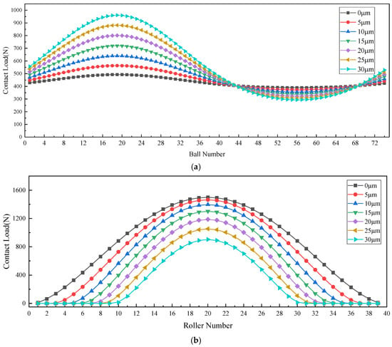
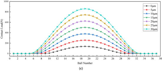
Figure 13.
Impact of circular surface radial deflection of outer ring on load distribution in multiple bearing rows loaded zones. (a) Load distribution in the loaded zone of a first-row angular contact ball bearing. (b) Load distribution in the loaded zone of a second-row angular contact roller bearing. (c) Load distribution in the loaded zone of a third-row angular contact ball bearing.
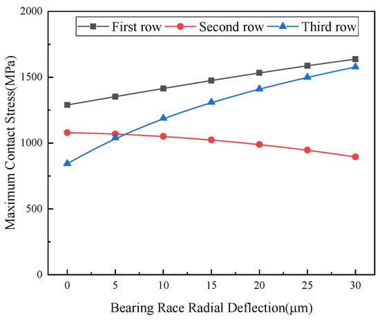
Figure 14.
Impact of outer ring raceway radial deflection on maximum contact stress in multi-row bearings.
This unbalanced load redistribution leads to multifaceted adverse effects: Ball bearings experience stress concentration owing to overloading, potentially causing premature failure, whereas roller bearings underperform by failing to adequately share the load, compromising the overall rigidity of the system. Furthermore, the ring deformation degrades the bearing positioning accuracy, exacerbates vibration and noise, and accelerates wear, thereby significantly reducing the bearing service life. Consequently, accounting for ring deformation effects is critical when analyzing the influences of other variable factors, as they fundamentally impact the bearing performance assessment.
3.3. Analysis of the Effect of Rolling Element Quantity on Bearing Performance
3.3.1. Analysis of Ball Quantity Effects on Bearing Performance
Figure 15 illustrates the influence of angular contact ball quantity on load distribution and maximum contact stress under Condition 1, which included 78 cylindrical rollers and 0 axial and radial clearances. As the number of balls increases, the radial load of the ball bearing row increases. when the number of loaded balls increases from 35 to 39, the load zone increases and reducing the maximum contact load per ball decreases. The enhanced load-carrying capacity of the ball bearing row simultaneously decreases the external load and maximum contact load. This balanced load redistribution improves the stress distribution uniformity, leading to a reduction in the maximum contact stress for all bearing rows as the ball count increases.
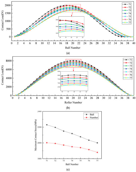
Figure 15.
Impact of ball quantity on mechanical performance in multi-row bearings. (a) Impact of ball quantity on load distribution in the loaded zone of angular contact ball bearings. (b) Impact of ball quantity on load distribution in the loaded zone of cylindrical roller bearings. (c) Impact of ball quantity on maximum contact stress of each row of bearings.
3.3.2. Analysis of Roller Quantity Effects on Bearing Performance
Figure 16 shows the influence of the number of cylindrical rollers on load distribution and maximum contact stress for each bearing row under Condition 1, with 74 balls and 0 axial and radial clearance. As the number of rollers increases from 37 to 39, the load-bearing zone expands. This leads to a higher overall radial load capacity in the roller bearing row and reduces its maximum contact load. This load redistribution decreases the external force on the ball bearing row, consequently lowering its maximum contact load. The enhanced load sharing results in a more uniform load distribution across all bearing rows, with each row exhibiting a reduced maximum contact stress as roller quantity increases. This demonstrates that an optimized roller count improves both load-bearing efficiency and stress distribution in multi-row bearing systems under preloaded conditions.
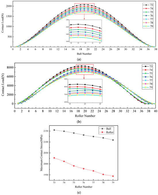
Figure 16.
Impact of roller quantity on mechanical performance in multi-row bearings. (a) Impact of roller quantity on load distribution in the loaded zone of angular contact ball bearings. (b) Impact of roller quantity on load distribution in the loaded zone of cylindrical roller bearings. (c) Impact of roller quantity on maximum contact stress of each row of bearings.
3.4. Analysis of Contact Angle Effects on Bearing Performance
Figure 17 shows the effect of the ball contact angle on load distribution and maximum contact stress across bearing rows under Condition 2, with 74 balls, 78 rollers, and 0 axial and radial clearance. Increasing the contact angle reduces the radial load carried by both ball bearing rows: The first row shows a decreasing radial force and resultant load reduction, whereas the third row exhibits a diminished load zone and reduced maximum contact load owing to its lower radial load share. This load redistribution increases the external force applied to the roller bearing row, thereby elevating both the maximum roller contact load and corresponding contact stress. Conversely, the maximum contact stress of the balls progressively decreases with increasing contact angle. The results demonstrate the critical role of contact angle selection in balancing multi-row bearing load sharing and stress optimization under zero-clearance preload conditions.
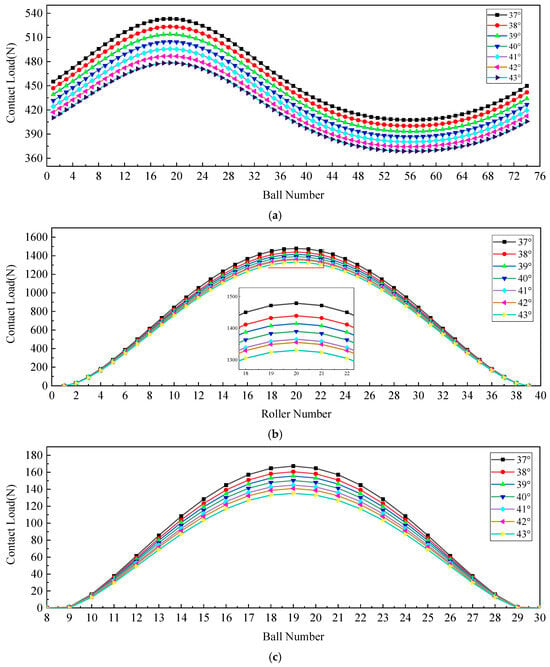
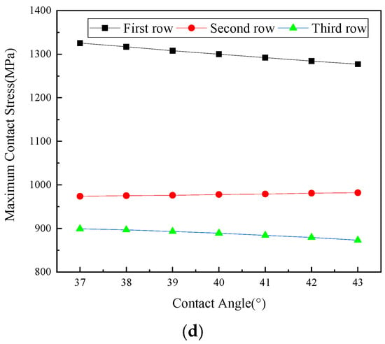
Figure 17.
Impact of contact angle on mechanical performance in multi-row bearings. (a) Impact of contact angle on load distribution in the bearing region of first-row ball bearings. (b) Impact of contact angle on load distribution in the bearing region of second-row roller bearings. (c) Impact of contact angle on load distribution in the bearing region of third-row ball bearings. (d) Impact of contact angle on the maximum contact stress of each row of bearings.
3.5. Analysis of the Influence of Radial Clearance in Multi-Row Bearings on Performance
3.5.1. Analysis of the Effect of Radial Clearance of Ball Bearings on Ball–Column Composite Bearing Performance
To prevent excessive clearance variations and potential bearing seizure under heavy-load and high-temperature operations, a positive clearance design is implemented for the ball–cylinder hybrid bearing. The following analysis is based on Condition 3, which examines how radial clearance modifications affect the load distribution and contact stress across the bearing rows.
With a fixed radial clearance of the roller column, variations in the radial clearance of the ball column significantly alter the load and stress distributions between the two bearing components, as shown in Figure 18. An increase in the radial clearance of the ball column results nonlinearly reduces the number of load-carrying rolling elements, which substantially decrease the overall external load-bearing ratio. According to Hertzian contact theory, this adjustment synchronously reduces both the maximum contact load and stress within the ball column. Simultaneously, the load redistribution effect compels the roller column to sustain a greater proportion of the external load, thereby increasing its loaded rolling elements and corresponding contact stresses. Under light-load conditions, a moderate enlargement of the radial clearance of the ball column can facilitate a transition toward a ball-dominated load distribution pattern for optimized system performance.
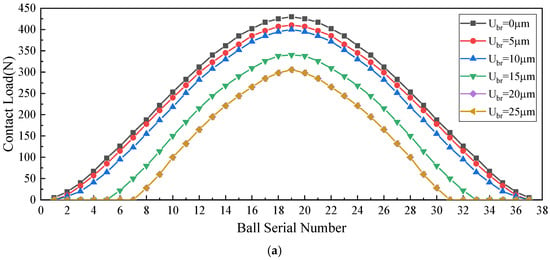
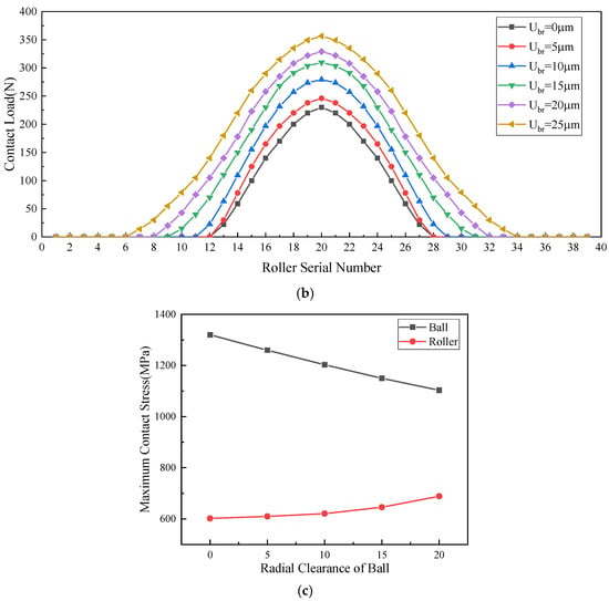
Figure 18.
Impact of radial clearance of ball row on mechanical properties of each row bearing. (a) Impact of radial clearance of ball rows on load distribution within the loaded zone of ball bearings. (b) Impact of radial clearance of ball rows on load distribution within the loaded zone of roller bearings. (c) Impact of radial clearance of ball rows on maximum contact stress of each row bearing.
3.5.2. Analysis of the Effect of Radial Clearance of Roller Bearings on Ball–Column Composite Bearing Performance
Adjusting the of roller race radial clearance while maintaining a constant ball race radial clearance significantly modifies the load distribution and contact stress characteristics in hybrid bearings, as illustrated in Figure 19. The findings demonstrate that an increased roller race clearance markedly reduces the number of loaded rolling elements in the roller column, consequently diminishing its load-bearing capacity. This geometric variation, analyzed using Hertzian contact theory, produces a coupled decrease in both the peak contact load and the resultant stress within the roller assembly. Concurrently, the load redistribution mechanism shifts a greater portion of the external loading to the ball column, inducing proportional increases in both the quantity of stressed ball elements and their corresponding maximum contact loads. This load transfer generates substantially elevated contact stresses within the ball raceway, potentially affecting the overall bearing performance characteristics.
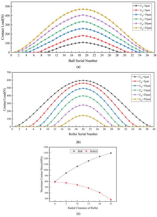
Figure 19.
Impact of radial clearance of roller row on mechanical properties of each row bearing. (a) Impact of radial clearance of roller row on load distribution within the loaded zone of ball bearings. (b) Impact of radial clearance of roller row on load distribution within the loaded zone of roller bearings. (c) Impact of radial clearance of roller row on the maximum contact stress of each row bearing.
The analysis reveals that with a ball race radial clearance of approximately 10 μm and roller race clearance of 20 μm, the hybrid bearing system exhibits distinct load-sharing characteristics across operating conditions. Under light loads, angular contact ball bearings predominantly support external loads. As radial loading increases, sufficient elastic deformation eliminates the roller bearing clearance, enabling load sharing. Under heavily loaded conditions, the system automatically transfers approximately 70–90% of the radial load to the roller column, leveraging its superior radial stiffness and linear contact stress distribution. Simultaneously, the ball bearings transition to supporting residual axial loads with minimal radial contributions. This mode utilizes the angular contact ball bearings’ high rigidity and low friction to maintain rotational accuracy while preventing roller column skidding damage from partial unloading effects under boundary lubrication, consequently improving transmission efficiency. However, excessive radial clearance can compromise performance. It may induce ball race radial runout and potentially trigger dynamic roller impacts during sudden load shifts, as inertial effects or step loading could cause momentary rolling element collisions, ultimately degrading the overall rotational precision of the hybrid bearing.
4. Conclusions
This study develops a mechanical analysis model based on the flexible raceway theory to investigate the adaptive gradient load-sharing mechanism of ball–column composite bearing. The key findings are summarized as follows:
- (1)
- Increased radial deflection of raceways triggers load redistribution, shifting external loads from roller bearings toward ball bearings. This disrupts the designed load distribution pattern, causes abnormal clearance distribution among the three bearing rows, elevates ball row loading, and induces significant stress concentration under heavy loads, ultimately degrading the bearing fatigue life.
- (2)
- Increasing the number of loaded rolling elements enhances load distribution uniformity and reduces the maximum contact stress, thereby increasing bearing capacity. Conversely, larger contact angles in the ball row weaken radial load capacity, forcing roller rows to share more radial loads for dynamic load redistribution.
- (3)
- Through optimized initial clearance matching among three bearing rows, a compliance-based load-sharing mechanism is established. Under light loads, angular contact ball bearings primarily provide stiffness while roller bearings remain non-load owing to positive clearance. When the load increases, elastic deformation eliminates roller bearing clearance for gradual load participation. Under heavy loads, approximately 70–90% of the radial load is borne by roller bearings, while the ball bearings transition to auxiliary roles, enabling efficient self-adaptive load distribution. Although adaptive gradient load-sharing has been achieved through coarse clearance adjustment, future research requires precise, coordinated control of three-row clearances to optimize the load distribution characteristics.
While our computational model exhibits reasonable agreement with Romax simulations, certain discrepancies can be attributed to inherent limitations of the commercial software, including constrained bearing customization capabilities, oversimplified structural rigidity assumptions, and inadequate handling of hybrid bearing configurations. Our developed analytical framework presents distinct advantages by capturing critical mechanical behaviors often neglected in commercial solutions, notably through its unified treatment of the three-row outer ring as a continuous elastic structure and explicit integration of outer ring arc surface deformation effects on load distribution and bearing performance. While this study has successfully established a robust theoretical foundation, we recognize that experimental validation remains an important direction for further research. Future investigations should incorporate both physical testing and numerical analysis to systematically evaluate ball–column size effects, clearance–load distribution relationships, and optimal configuration strategies. Such comprehensive validation efforts would not only strengthen the predictive capabilities of our physics-based approach but also further demonstrate its advantages over conventional commercial solutions for complex bearing system analysis.
Author Contributions
All authors contributed to the study conception and design. Material preparation, data collection, analysis, and funding acquisition were performed by G.L., Y.C., H.W., Z.Y., and Y.N. The first draft of the manuscript was written by G.L., Y.C., and Y.N., and all authors commented on previous versions of the manuscript. All authors have read and agreed to the published version of the manuscript.
Funding
This work was supported by the XZ-FH Bearing Development Program (XZ-FH-2023-067).
Data Availability Statement
The data used to support the findings of this study are available from the corresponding author upon request.
Conflicts of Interest
Authors Hedong Wei and Zhiwen Yang were employed by the company Guizhou Tianma Hongshan Bearing Co., Ltd. There remaining authors declare that the research was conducted in the absence of any commercial or financial relationships that could be construed as a potential conflict of interest.
References
- Deng, S.E.; Jia, Q.Y.; Xue, J.X. Fundamentals of Rolling Bearing Design; China Standards Press: Beijing, China, 2024. (In Chinese) [Google Scholar]
- Stribeck, R. Ball bearings for various loads. J. Trans. ASME 1907, 29, 420–467. [Google Scholar]
- Zupan, S.; Prebil, I. Carrying angle and carrying capacity of a large single row ball bearing as a function of geometry parameters of the rolling contact and the supporting structure stiffness. Mech. Mach. Theory 2001, 36, 1087–1103. [Google Scholar] [CrossRef]
- Kania, L. Modelling of rollers in calculation of slewing bearing with the use of finite elements. Mech. Mach. Theory 2006, 41, 1359–1376. [Google Scholar] [CrossRef]
- Smolnicki, T.; Derlukiewicz, D.; Stańco, M. Evaluation of load distribution in the superstructure rotation joint of single-bucket caterpillar excavators. Autom. Constr. 2007, 17, 218–223. [Google Scholar] [CrossRef]
- Daidié, A.; Chaib, Z.; Ghosn, A. 3D Simplified Finite Elements Analysis of Load and Contact Angle in a Slewing Ball Bearing. J. Mech. Des. 2008, 130, 082601. [Google Scholar] [CrossRef]
- Cavallaro, G.; Nelias, D.; Bon, F. Analysis of High-Speed Intershaft Cylindrical Roller Bearing with Flexible Rings. Tribol. Trans. 2005, 48, 154–164. [Google Scholar] [CrossRef]
- Aguirrebeitia, J.; Abasolo, M.; Avilés, R.; de Bustos, I.F. Theoretical calculation of general static load-carrying capacity for the design and selection of three row roller slewing bearings. Mech. Mach. Theory 2011, 48, 52–61. [Google Scholar] [CrossRef]
- Göncz, P.; Potočnik, R.; Glodež, S. Computational model for determination of static load capacity of three-row roller slewing bearings with arbitrary clearances and predefined raceway deformations. Int. J. Mech. Sci. 2013, 73, 82–92. [Google Scholar] [CrossRef]
- Göncz, P.; Drobne, M.; Glodež, S. Computational model for determination of dynamic load capacity of large three-row roller slewing bearings. Eng. Fail. Anal. 2013, 32, 44–53. [Google Scholar] [CrossRef]
- Noel, D.; Ritou, M.; Furet, B.; Le Loch, S. Complete Analytical Expression of the Stiffness Matrix of Angular Contact Ball Bearings. J. Tribol. 2013, 135, 041101. [Google Scholar] [CrossRef]
- Tong, V.-C.; Hong, S.-W. Characteristics of tapered roller bearing subjected to combined radial and moment loads. Int. J. Precis. Eng. Manuf. Technol. 2014, 1, 323–328. [Google Scholar] [CrossRef]
- Zhang, R. Analysis of radial stiffness of elastic composite cylindrical roller bearings. Master’s Thesis, Hunan University of Technology, Zhuzhou, China, 2014. (In Chinese). [Google Scholar]
- Korolev, A.A.; Kreheľ, R. Character of distribution of the load between the balls in the ball bearings under the action combined of external load. Mech. Mach. Theory 2014, 81, 54–61. [Google Scholar] [CrossRef]
- Li, Y. Analysis of influencing parameters on load capacity of wind turbine pitch slewing bearings. Taiyangneng Xuebao 2018, 39, 3253–3260. [Google Scholar] [CrossRef]
- Hao, X.; Gu, X.; Zhou, X.; Liao, X.; Han, Q. Distribution characteristics of stress and displacement of rings of cylindrical roller bearing. Proc. Inst. Mech. Eng. Part C J. Mech. Eng. Sci. 2019, 233, 4348–4358. [Google Scholar] [CrossRef]
- Li, Y.; Jiang, D.; Song, L. Finite element analysis of wind turbine pitch bearings considering the installation structure. Taiyangneng Xuebao 2019, 40, 2021–2027. [Google Scholar] [CrossRef]
- Heras, I.; Aguirrebeitia, J.; Abasolo, M.; Coria, I.; Escanciano, I. Load distribution and friction torque in four-point contact slewing bearings considering manufacturing errors and ring flexibility. Mech. Mach. Theory 2019, 137, 23–36. [Google Scholar] [CrossRef]
- Fang, B.; Zhang, J.; Yan, K.; Hong, J.; Wang, M.Y. A comprehensive study on the speed-varying stiffness of ball bearing under different load conditions. Mech. Mach. Theory 2019, 136, 1–13. [Google Scholar] [CrossRef]
- Hao, X.; Zhai, J.; Liang, J.; Chen, Y.; Han, Q. Time-varying stiffness characteristics of roller bearing influenced by thermal behavior due to surface frictions and different lubricant oil temperatures. Tribol. Int. 2020, 144, 106125. [Google Scholar] [CrossRef]
- Li, J.; Lei, C.; Gong, B.; Cui, P.; Jia, X.; Lenka, T.R. Modeling and Analysis of the Composite Stiffness for Angular Contact Ball Bearings. Shock. Vib. 2020, 2020, 32750. [Google Scholar] [CrossRef]
- Rivera, G.; Tong, V.-C.; Hong, S.-W. Contact Load and Stiffness of Four-Point Contact Ball Bearings Under Loading. Int. J. Precis. Eng. Manuf. 2022, 23, 677–687. [Google Scholar] [CrossRef]
- Sinha, R.; Sahoo, V.; Paswan, M. Radial load distribution by balls in a ball bearing with variable clearance. Mech. Based Des. Struct. Mach. 2023, 51, 3538–3563. [Google Scholar] [CrossRef]
- Hou, Y.; Wang, X. Measurement of load distribution in a cylindrical roller bearing with an instrumented housing: Finite element validation and experimental study. Tribol. Int. 2021, 155, 106785. [Google Scholar] [CrossRef]
- Xu, H.; He, D.; Ma, H.; Yu, K.; Zhao, X.; Yang, Y. A method for calculating radial time-varying stiffness of flexible cylindrical roller bearings with localized defects. Eng. Fail. Anal. 2021, 128, 105590. [Google Scholar] [CrossRef]
- Wang, Y.; E, S.; Jia, Y.; Ma, X.; Xie, B. Improved quasi-static analysis model for angular contact ball bearings under combined loads. Bearing 2022, 11, 13–17. [Google Scholar] [CrossRef]
- Chen, D.; Li, P.; Sun, K.; Pan, R.; Tang, Y. Influence of Imbalance Factors Coupling with Manufacturing Error on the Rotational Accuracy of Aerostatic Spindle. Int. J. Precis. Eng. Manuf. 2023, 24, 1933–1946. [Google Scholar] [CrossRef]
- Zhu, D.; Pang, X.; Wang, D.; Qiu, M.; Liu, D.; Dong, Y.; Xu, B. Dynamic Analysis of Vertical Magnetic Suspension System Rotor Dropping to Protective Bearing with Different Structural Parameters. Int. J. Precis. Eng. Manuf. 2024, 26, 133–155. [Google Scholar] [CrossRef]
- Zeng, W.; Hu, S.; Huang, Y.; Lee, Y. Prediction of Quasi-static Ring Misalignment for Shaft-bearing System During Rotation Considering Multi-Datum Geometric Tolerances. Int. J. Precis. Eng. Manuf. 2025, 26, 1315–1333. [Google Scholar] [CrossRef]
- Lim, T.; Singh, R. Vibration Transmission Through Rolling Element Bearings, Part I: Bearing Stiffness Formulation. J. Sound Vib. 1990, 139, 179–199. [Google Scholar] [CrossRef]
- Dong, Y.; He, K.; Qiu, M.; Yan, Z.; Yu, W. Theoretical and experimental study on the thermomechanical characteristics of double-row angular contact automotive wheel bearings. Sci. Rep. 2025, 15, 24131. [Google Scholar] [CrossRef]
Disclaimer/Publisher’s Note: The statements, opinions and data contained in all publications are solely those of the individual author(s) and contributor(s) and not of MDPI and/or the editor(s). MDPI and/or the editor(s) disclaim responsibility for any injury to people or property resulting from any ideas, methods, instructions or products referred to in the content. |
© 2025 by the authors. Licensee MDPI, Basel, Switzerland. This article is an open access article distributed under the terms and conditions of the Creative Commons Attribution (CC BY) license (https://creativecommons.org/licenses/by/4.0/).