Abstract
Electro-hydraulic proportional multi-way valves are widely used in construction machinery and equipment, and their performance directly affects the operation performance of construction machinery and equipment. In this paper, an electro-hydraulic proportional multi-way valve was taken as the research object, and the precise control of the position of the spool of electro-hydraulic proportional multi-way valves under multi-source disturbances was studied. A mathematical model of the electro-hydraulic proportional multi-way valve was established to analyze the influence of hardware controller parameters on the control current. A proportional multi-way valve expansion state observer was established to observe the changes in internal and external multi-source disturbances, and a sliding mode controller was used to compensate for the influence of these disturbances on the position control accuracy of the valve spool of proportional multi-way valves. Compared with the PID control method, the results show that, when using the control method proposed in this paper, the reduction in the step response time and improvement in pressure control accuracy for the pilot proportional reducing pressure valve were maximally 44.4% and 0.61%, respectively; the reduction in the step response time and improvement in control accuracy for the spool of the pilot proportional multi-way valve were maximally 69.48% and 61.74%, respectively. The research results in this paper can help to improve the performance and multi-condition adaptability of electro-hydraulic proportional multi-way valves.
1. Introduction
An electro-hydraulic proportional multi-way valve is a core control component in hydraulic systems. As the demand for reliability, control accuracy, response speed, and intelligence and integration in hydraulic systems for equipment such as construction machinery and agricultural machinery continues to rise, the electro-hydraulic proportional multi-way valve becomes increasingly critical [1]. However, the electro-hydraulic proportional multi-way valve exhibits strong nonlinearity, and the application environment is subject to multi-source disturbances, making it difficult to ensure its dynamic and static characteristics, which, in turn, directly affects system performance [2,3]. Therefore, there is an urgent need to conduct research on the high-performance dynamic and static control of electro-hydraulic proportional multi-way valves under multi-source disturbance excitation.
To improve the performance of hydraulic valves, scholars at home and abroad have conducted extensive research on the performance of hydraulic systems. Hao Wang et al. established a mathematical model for the main valve displacement and output flow of high-pressure, high-flow-rate, high-frequency water hydraulic proportional flow valves, analyzing the influence of various parameters on the dynamic characteristics of the flow valves [4]. Xinqiang Liu et al. analyzed the erosion characteristics of servo valve spool orifices and developed an anti-erosion bionic structural optimization design [5]. Chengzhen Wang et al. established a corresponding mathematical model based on the working principle of a pilot-assisted balancing valve based on the hydraulic–mechanical feedback principle, analyzing the flow control characteristics, overcompensation characteristics, and the influence of backpressure on the main flow [6]. Fuyan Lyu et al. addressed the issue of significant axial transient vibration on both sides of the valve and minor radial transient vibration caused by the opening of the check valve, analyzing the vibration characteristics of high-pressure, long-distance, thick slurry pipelines using hydraulic active check valves [7]. Chenghu Guo analyzed the dynamic characteristics involved in the opening, unloading, overflowing, and closing of two-stage safety valves under impact [8]. Qianpeng Chen et al. addressed the clamping problem of the valve spool caused by thermal deformation, conducted viscous heating experiments on a V-shaped groove valve spool, and analyzed the thermal deformation and clamping force characteristics of a hydraulic valve spool [9]. Haibo Xie et al. established static equilibrium equations of a pilot-assisted load control valve and derived the mutual influence relationship between backpressure and other parameters, thereby analyzing the backpressure compensation characteristics of the pilot-assisted load control valve [10]. The aforementioned research on hydraulic valve performance primarily focuses on the influence of hydraulic fluid on the overall valve performance, without considering the influence of controllers.
Domestic and international scholars have conducted a series of studies on the high-performance control of hydraulic valves to improve their performance. Chen Lei et al. proposed state feedback control with integral compensation for the displacement control of servo proportional valve cores, compensating for the nonlinearity and uncertain parameters of hydraulic valves and eliminating the steady-state error of displacement tracking [11]. Ma et al. proposed a sliding mode variable structure control algorithm for nonlinear problems caused by internal valve leakage and uncertainties in the working environment, meeting the basic control requirements of the system and being insensitive to system parameters [12]. Qiang Gao proposed an improved PWM controller for the position control of the main valve core in high-speed solenoid valves, with the proposed PWM control reducing the maximum impact acceleration by at least 44.7% and maintaining a total opening time delay of less than 0.3 ms [13]. Tobia et al. derived a controller design model encapsulating key nonlinearities for the position control of directional control valves and employed a cascade control algorithm, effectively compensating for the valve’s nonlinearity and improving position control accuracy [14]. Xing Yang et al. proposed a pressure adaptive multi-level voltage and sliding mode control algorithm for water hydraulic high-speed on–off valves, enabling the on–off valves to switch rapidly and maintain dynamic characteristics under varying environmental pressures [15]. The research on hydraulic valve control methods mentioned above provides certain directional guidance for the high-performance control of the core position of the proportional multi-way valve in this paper.
The proportional multi-way valve spool position control link is mainly composed of three parts, namely, a proportional controller, a proportional reducing pressure valve, and a multi-way valve, which belongs to a typical electro-hydraulic servo nonlinear system, and a lot of research has been carried out on the electro-hydraulic servo position control system by scholars at home and abroad. Deptuła et al. proposed a method for designing hydraulic valves by using multivalued logic trees and weighted factors to determine the structure and the method of the operating parameters of two-stage proportional safety valves, addressing the technical issues of the studied proportional valve series [16]. Stosiak et al. proposed a different fluid model and hybrid friction model for the impact of mechanical oscillation on hydraulic direction control valves, significantly improving the consistency between simulation and experimental results [17]. Feng et al. proposed an improved PSO algorithm in view of the shortcomings of the basic particle swarm optimization algorithm on the electro-hydraulic position servo system of robot excavators in terms of convergence speed and the avoidance of local optimal solutions [18]. Wang et al. proposed a counterstep controller based on a tracking differentiator (TD), which reduces the complexity of the implementation process of the backstep controller, analyzes the performance difference and stability between the alternative signal and the original signal, and ensures tracking accuracy [19]. Sun et al. proposed a sliding mode control method based on the adaptive approximation law to effectively reduce the jitter and improve the robustness of the system [20]. For precise position adjustment in hydraulic servo systems, Kaixian Ba et al. proposed a self-disturbance control method based on matrix sensitivity, which effectively reduced nonlinear interference and significantly reduced peak error [21]. Xiangfei Tao et al. proposed a sliding mode backstep control strategy based on the particle swarm optimization algorithm and a neural network disturbance observer to control the system input through the general approximation characteristics of the observer through neural network interference [22]. Zhang et al. proposed a composite control method based on sliding mode and self-impulse control to solve the problem that the boom tunneling electro-hydraulic servo system is difficult to control under the conditions of parameter changes and uncertain disturbances, and it improved the tracking accuracy and robustness of the position servo system compared with traditional self-interference control, PID, and sliding mode control [23]. Zhang et al. developed a direct neural adaptive self-disturbance controller to solve the problems of uncertainty and large external disturbance of the electro-hydraulic servo system of high-order nonlinear systems of engineering mining machinery, and simulation results showed that the direct neural adaptive self-disturbance controller has good tracking accuracy and robustness [24]. Zhuang et al. proposed a control method that combines sliding mode control and extended state observer control for the position control of electro-hydraulic servo systems with nonlinear mechanical dynamics, which effectively compensates for the influence of internal and external disturbances on control performance [25]. Yu et al. proposed the closed-loop working principle of an electro-hydraulic load-sensing hydraulic power unit for addressing the mismatch in the pressure and flow rate of hydraulic drive components, derived mathematical models for key components with strong nonlinearity and time-varying parameters, and introduced a matching control strategy based on flow rate feedforward and pressure differential compensation feedback. Simulation and experimental results verified the feasibility of the system and its matching control strategy [26]. Mou et al. designed an active load-sensing variable displacement drive system that does not rely on mechanical structures for load-sensing adjustment to address issues such as a reduced dynamic response speed and limited load-sensing range. They proposed a dual-loop anti-disturbance control method based on energy efficiency mapping, which improved the system’s position control accuracy [27]. The above research on the position control method of electro-hydraulic servo systems provides a certain directionality for the high-performance position control of the spool position of proportional multi-way valves with a pilot stage.
To realize the high-performance control of the proportional multi-way valve spool position, this paper takes the proportional multi-way valve spool position control system as the research object. By utilizing the linear extended state observer (LESO) to estimate disturbances, combined with sliding mode control (SMC) for its model insensitivity and strong robustness characteristics, this paper analyzes the influence of controller hardware parameters on the output current, and it proposes a sliding mode control algorithm based on a linear extended state observer (abbreviated as LESO-SMC throughout the following text) to address the impact of nonlinear forces, such as hydrodynamic and friction forces, as well as internal and external multi-source disturbances, on the proportional multi-way valve spool position control performance. A comparative analysis is conducted with the PID control method to verify the effectiveness of the proposed control strategy in enhancing the dynamic and static performance of the proportional multi-way valve spool position control in both the pilot stage and the entire valve.
2. Mathematical Modeling and Influencing Factor Analysis of Proportional Multi-Way Valves
2.1. Working Principle
Figure 1 shows a cross-sectional view of a multi-way valve that supports both manual and electro-hydraulic control. Among them, the electro-hydraulic control adopts two plug-in proportional reducing pressure valves to control the pressure or flow of the multi-way valve’s pilot inlet and pilot outlet, thereby driving the multi-way valve spool to actuate. The yellow, red, orange, blue, and green parts shown in the figure respectively represent the pilot oil, high-pressure oil, oil entering the main valve, oil returning to the oil tank, and A/B port oil. Figure 2 shows a diagram of the hydraulic principle of a multi-way valve, dashed lines indicate oil routes with lower flow.
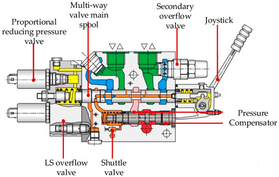
Figure 1.
Profile of a multi-way valve.
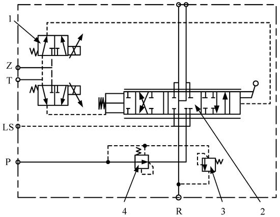
Figure 2.
Diagram of main hydraulic principle of multi-way valve: 1—proportional reducing pressure valve; 2—main valve; 3—secondary overflow valve; 4—pressure compensator.
The proportional reducing pressure valve, as the direct control object of the proportional spool position control system of the proportional multi-way valve, is controlled by a proportional controller. The proportional controller receives instruction signals applied from the outside and outputs control signals to control the outlet pressure of the proportional reducing pressure valve, ultimately driving the multi-way valve spool to actuate. The performance of the proportional controller directly affects the performance of the proportional multi-way valve spool position control system. To ensure precise control of the multi-way valve spool position, a closed-loop system is required for high-precision control. The structure of the proportional multi-way valve spool position control system is shown in Figure 3.
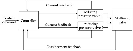
Figure 3.
Structure diagram of proportional multi-way valve spool position control system.
First, the controller receives external control command signals, which are processed by the microprocessor chip and output as two control signals to the proportional reducing pressure valve. The detection circuit forms a current internal closed loop, ensuring that the outlet pressure of the proportional reducing pressure valve remains stable. The output pressure of the proportional reducing pressure valve controls the actuator movement of the multi-way valve. The LVDT displacement sensor signal, after being conditioned by the detection circuit, forms a position external closed loop, achieving precise control of the multi-way valve actuator position. Due to the limited driving capability of the microprocessor chip, a driving circuit needs to be added to drive the proportional reducing pressure valve.
2.2. Mathematical Model of Proportional Multi-Way Valve
- 1.
- Analysis of the controller output current model and influencing factors
The working process of the PWM-driven reverse connection unloading drive circuit is shown in Figure 4, where the solid line loop represents the charging process, and the dashed line loop represents the unloading process, with the following simplifications:
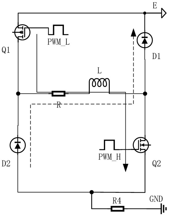
Figure 4.
Reverse connection unloading drive circuit.
(1) In practical applications, the proportional electromagnet is generally operated in the linear region, ignoring the nonlinear factors of the proportional electromagnet, and the proportional electromagnet is equivalent to a series connection of resistance and inductance.
(2) During the charging and unloading processes of the proportional electromagnet, there are also sampling resistor, diode, and MOS on-resistances, as well as internal resistance of the power supply. It is assumed that the total resistance during charging and unloading is equal, both being .
When the charging process of the proportional electromagnet is , the function of the current of the proportional electromagnet to time is
Then, the average current of the [0, T] period is
In the formula, is the power supply voltage (V); is the equivalent inductance of the proportional solenoid (mH); is the equivalent resistance of the proportional solenoid (); and is the current of the proportional solenoid as a function of time (A). is the current of the proportional solenoid at zero initial time (A); is the circuit time constant; and is a constant. It is assumed that the total resistance during charging and unloading is equal, both being . is the PWM duty cycle, ; T is the PWM period (s).
The average current in the period [KT, (K + 1)T] is
To analyze the impact of the controller hardware parameters on the performance of a pilot-operated proportional valve, the proportional valve’s pilot-stage solenoid drive power supply is given as a 24V DC power signal. The current magnitude under different resistances, different inductances, and different PWM frequencies is analyzed, as well as the variation in the current ripple amplitude under different PWM frequencies and PWM duty cycles. The simulation results are shown in Figure 5.
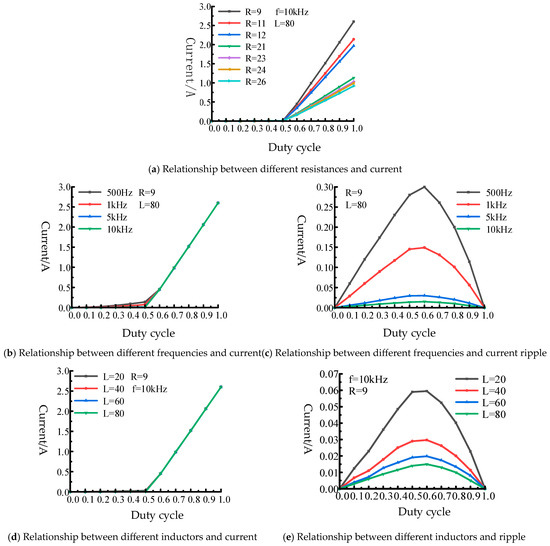
Figure 5.
Simulation results of the reverse connection unloading drive circuit.
As shown in Figure 5, the average current size of the proportional electromagnet is mainly affected by resistance, with the maximum current steady-state value being ; the current size of the proportional electromagnet is less affected by the PWM frequency and inductance parameters, and it can be ignored. In (a), it can be seen that, when the PWM duty cycle is less than 0.5, the current of the proportional electromagnet is very small and can be ignored; when the PWM duty cycle is greater than 0.5, the current of the proportional electromagnet shows a very good linear relationship with the duty cycle, so the adjustment range of the reverse connection unloading drive circuit is between . It can also be seen in Figure 5c,e that the current ripple is mainly affected by the PWM frequency and inductance. The higher the PWM frequency, the smaller the current ripple and the smoother the current waveform. The larger the inductance, the smaller the current ripple. Additionally, the maximum amplitude of the current ripple occurs near a duty cycle of 0.5–0.6. The current ripple is one of the important performance indicators of PWM-driven reverse polarity discharge drive circuits. An excessive current ripple can cause the proportional electromagnet to operate frequently, not only increasing the loss and temperature change of the proportional electromagnet itself but also exacerbating the valve core vibration and mechanical wear of the proportional reducing pressure valve, reducing the service life of the proportional reducing pressure valve, and increasing the control difficulty of the proportional reducing pressure valve.
- 2.
- State-space model of pilot-type electro-hydraulic proportional valve
Since the single-plate spool of the proportional multi-port valve has symmetrical left and right structures, the transfer function of spool displacement y to spool displacement x of the proportional reducing pressure valve in the pilot stage is
In the formula, is the flow gain coefficient; is the main spool force area of the multi-way valve (m3); is the natural frequency, ; is the damping ratio, ; is the total volume of the main spool of the multi-way valve (m3); is the viscous damping coefficient (N·s/m); is the total mass of the main spool of the multi-way valve (kg); is the oil volume elastic modulus (Pa); is the inner and outer leakage coefficient (m3/s·Pa); and is the flow/pressure gain coefficient of the proportional reducing pressure valve.
The inherent frequency of the proportional controller and the proportional reducing pressure valve is much higher than that of the proportional valve spool position control system. Simplifying the proportional controller and the proportional reducing pressure valve as a proportional element, that is, ensuring that the displacement of the proportional reducing pressure valve spool is linearly related to the input current of the proportional controller, yields the transfer function of the proportional valve spool position control system:
In the formula, .
, , and are the displacement, velocity, and acceleration of the spool of the proportional multi-way valve, respectively. Then, the state equation of the proportional multi-way valve is
In the formula, , , , .
3. Control Algorithms
The proportional multi-way valve spool position control system contains nonlinear factors such as hydrodynamic forces, friction forces, electrical signal interference, external load characteristics, time-varying hydraulic parameters, and proportional controllers, as well as internal disturbances and external disturbances such as superimposed random interference from external signals.
To address the impact of nonlinear hydrodynamic forces and multi-source internal and external disturbances on the position control performance of the spool in a pilot proportional multi-way valve, LESO is employed to estimate the total disturbance of the system. LESO-SMC is established, with its structure shown in Figure 6, thereby improving the control accuracy and anti-interference performance of the spool position control system in the pilot proportional multi-way valve.
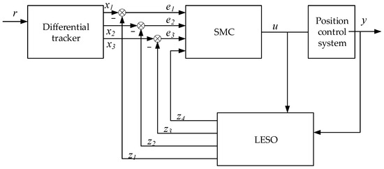
Figure 6.
LESO-SMC structure diagram.
A new total disturbance state x4 is added to the system of Equation (6), and . Therefore, the state equation of the pilot electro-hydraulic proportional multi-way valve after expansion is
In the formula, , , , , where is the known input part.
3.1. Differential Tracker
For second-order discrete systems,
Derive a differential tracker based on the fastest synthesis function :
In the formula, represent the system state; are the control parameters of the fastest synthesis function; and is the system sampling period. is the filter factor. Generally, can be taken as an integer multiple of . Adjusting the speed factor regulates the speed of tracking the input signal.
Four state variables are obtained by cascading four differential trackers, and the differential signal of the fourth differential tracker is discarded. The differential trackers established are
The specific form of is
In the formula, is the adjustment speed factor, is the filter factor, and is the system sampling period.
3.2. Expansion State Observer
- 1.
- Establishment of an extended state observer
The extended state space equation of the proportional multi-port valve spool position control system is shown in Equation (7), where is the derivative of and is bounded, ultimately establishing a linear extended observer:
In the formula, , , , .
In the formula, is the state observer gain. Using the bandwidth parameterization method, with the observer bandwidth determined, all poles are configured at , .
- 2.
- Stability Analysis of the Expansion State Observer
The error of the extended state observer is the difference between the system state and the estimated state . Therefore, the extended state observer error is , the differential of the extended state observer error is , and, accordingly, the error equation of the extended state observer is obtained
Assumption: For the error equation of expression (13), is bounded, meaning that there exists a number, not less than 0, making , . From this, the error state space equation of the extended state observer can be derived:
In the formula, ,.
The characteristic polynomial of the error state space equation of the expanded state observer is
By choosing to make be Hurwitz, for any given symmetric positive definite matrix , there exists a symmetric positive definite matrix that satisfies the following Lyapunov equation:
The Lyapunov function that defines the error state space equation of the extended state observer is
Then,
And
In the formula, is the smallest eigenvalue of .
From , the condition for the convergence of the extended state observer is
If the convergence condition of Equation (20) is satisfied, then the expansion state observer designed in this paper is stable, and the estimation error is bound.
3.3. Sliding Mode Control Law
- 1.
- Design of sliding mode control law
An LESO simulation model is built using a fourth-order LESO, with the input being two signals, namely, the control law output quantity and the system output, and the output being the control system estimated state of three proportional multi-way valve spool positions and one total disturbance estimated state. SMC takes the difference between the differential tracker’s output and LESO’s estimated state output, along with LESO’s total disturbance estimated output, as inputs, performs calculations, and outputs the control quantity.
To compensate for the impact of the disturbance state variable x4 on the position control of the spool in the lead-type electro-hydraulic proportional valve, a sliding mode control law is designed. The displacement reference signal of the proportional multi-way valve spool is defined as , and the actual errors of the system are defined as , , and . Then, the error equation of the system is
The sliding face is selected as
In the formula, , , and , are constants, taking . as the system bandwidth.
The observation error of the system is , , , and the observation sliding surface is selected as
Taking the derivative of Equation (22) yields
The Lyapunov function is set as
Taking the derivative of Equation (25) yields
Based on the exponential convergence law, the control law is designed as
In the formula, , .
- 2.
- Stability Analysis of Sliding Mode Control System
By substituting Equation (27) into Equation (26), we obtain
In Section 3.2, it can be seen that the expansion state observer converges; then, is bounded and sufficiently small, so , and the sliding mode control law is stable.
4. Analysis of Simulation Results for Proportional Multi-Way Valve Spool Position Control System
To verify the effectiveness of the control strategy proposed in this paper, a simulation analysis is performed on the lead-type proportional multi-way valve under commands such as step and sinusoidal.
4.1. Analysis of Step Simulation Results
Under the conditions of an initial position of 0.1 m and a system pressure of 3 MPa, the control effect of the proportional multi-way valve spool position control system is verified using the sliding mode control algorithm and the PID control algorithm under a given step signal. The simulation is mainly divided into four operating conditions, which are specifically shown in Table 1. The corresponding simulation results are shown in Figure 7.

Table 1.
Simulation parameters of step signals.
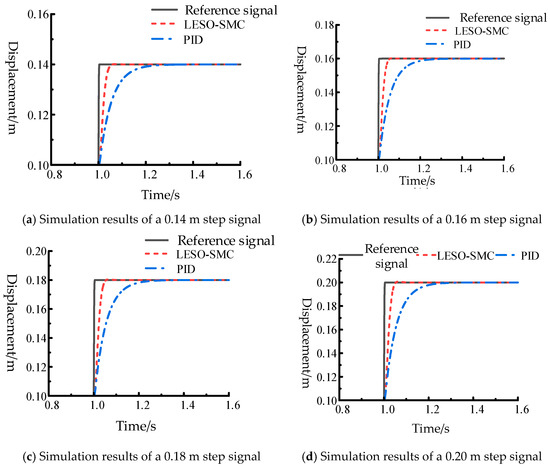
Figure 7.
Simulation results of step signals.
The simulation results in Figure 7 for the four different step signals of 0.14 m, 0.16 m, 0.18 m, and 0.2 m indicate that, under the same conditions, the control effect of the LESO-SMC algorithm on the proportional multi-port valve spool position control is significantly better than that of the PID control algorithm. The rise time and adjustment time of the LESO-SMC algorithm are both smaller than those of the PID control algorithm, allowing it to reach the desired position faster. The specific data on the rise time and adjustment time of the LESO-SMC algorithm and the PID control algorithm are shown in Table 2. In Table 2, it can be seen that, under the four different step signals of 0.14 m, 0.16 m, 0.18 m, and 0.2 m, the rise time of LESO-SMC is 74.9%, 75.8%, 76.1%, and 76.2% faster than that of PID, and the adjustment time of LESO-SMC is 73.5%, 73.6%, 73.3%, and 73.2% faster than that of PID.
Table 2.
Simulation performance parameters of step signals.
4.2. Analysis of Sinusoidal Simulation Results
The initial position of the spool in the pilot-operated proportional multi-way valve is set to 0.1 m, the supply pressure is set to 3 MPa, and the sinusoidal command is shown specifically in Table 3. The corresponding simulation results are shown in Figure 8 and Figure 9, respectively.
Table 3.
Parameters of sinusoidal signal.
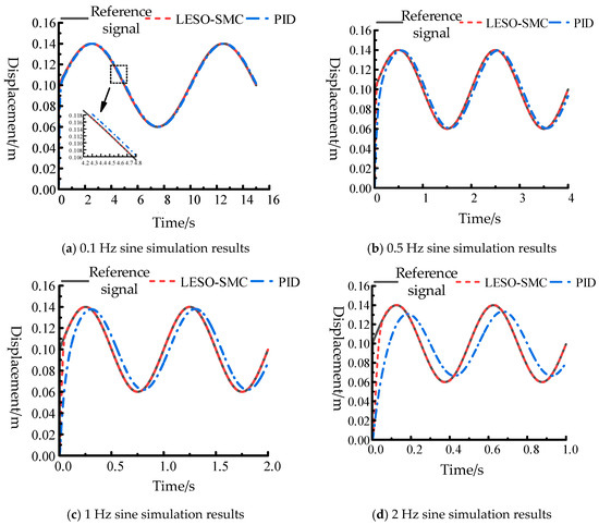
Figure 8.
Simulation results of sinusoidal signals.
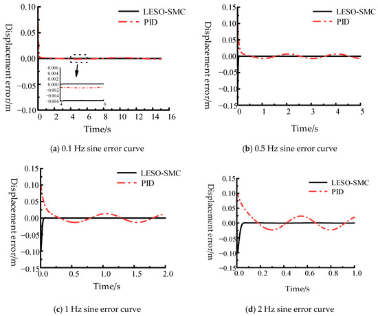
Figure 9.
Sinusoidal signal error curve.
As shown in Figure 8, the LESO-SMC algorithm has better tracking performance than the PID control algorithm. The LESO-SMC algorithm can always follow the desired target as the sine signal frequency increases, while the PID control algorithm shows increasing lag with frequency. The error curves of the LESO-SMC algorithm and the PID control algorithm when tracking the sine signal are shown in Figure 9. The simulation results in Figure 8 indicate that, under sine signals of 0.1 Hz, 0.5 Hz, 1 Hz, and 2 Hz, the tracking error of the LESO-SMC algorithm is significantly smaller than that of the PID control algorithm. The specific tracking error data are shown in Table 4. In Table 4, it can be seen that the tracking performance of LESO-SMC is better than that of PID under three different frequencies of sinusoidal signals (0.5 Hz, 1 Hz, and 2 Hz). The error rates of LESO-SMC are 0.05%, 0.18%, and 0.74%, respectively, while the error rates of PID are 17.23%, 33.19%, and 58.59%, respectively.
Table 4.
Simulation results of sinusoidal following error.
5. Experimental Verification
To further verify the effectiveness of the control strategy proposed in this paper, a pilot electric-hydraulic proportional multi-way valve position test simulation platform was built, and, based on this platform, the control effects of the spool positions of the pilot proportional reducing pressure valve and the proportional multi-way valve under different commands were analyzed.
5.1. Experimental Platform
As shown in Figure 10, the displacement of the hydraulic cylinder is controlled by two proportional reducing pressure valves to simulate the displacement of the main valve core of the proportional multi-way valve, and the proportional controller sends a PWM control signal to convert the driving voltage into the output pressure of the proportional reducing pressure valve to control the driving current, in which the proportional reducing pressure valve can be controlled separately. The signals from the pressure sensor and displacement sensor are stored and displayed through a data acquisition card. The model and accuracy of the sensors and controller chip are shown in Table 5. The current is collected from the controller chip. No. 46 anti-wear hydraulic oil is used, and the oil temperature is maintained within 50 ± 5 °C during system operation.
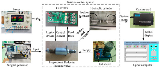
Figure 10.
Position test simulation platform for pilot-type electro-hydraulic proportional multi-way valve.
Table 5.
Sensor model.
5.2. Signal Flow Diagram
The software program of the controller is the key to its normal operation, enabling the main control chip to run the module functions in the predetermined manner, serving as the brain of the proportional multi-way valve spool position control system. The proportional controller program is written using the Keil uVision5 integrated development environment. The overall software framework of the proportional controller is shown in Figure 11.
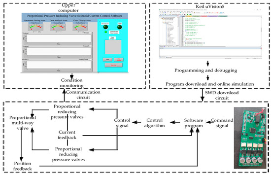
Figure 11.
Proportional controller software framework.
5.3. Proportional Reducing Pressure Valve Control Test
To verify the control effect of the proportional controller on the pilot-stage proportional reducing pressure valve, step signals and sinusoidal signals were selected to test the current pressure control effect of the proportional reducing pressure valve.
First, a step response test was performed to verify the current pressure control effect of the proportional reducing pressure valve under the given conditions of 3 MPa pressure and a voltage step signal amplitude of 0–5 V. The specific step signal amplitudes and their corresponding current signal amplitudes are shown in Table 6.
Table 6.
Step signal condition.
The current pressure step response test results obtained under four operating conditions and presented in Table 6 are shown in Figure 12, and the step response performance parameters are listed in Table 7.
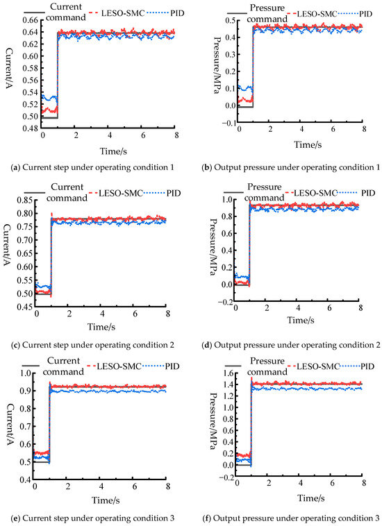
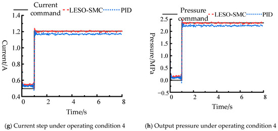
Figure 12.
Step response test results.
Table 7.
Step response performance parameters.
As can be seen in Figure 12 and Table 7, compared with PID control, the proportional reducing pressure valve responds faster under LESO-SMC control, and, from the perspective of rising time, LESO-SMC is 44.4%, 18.18%, 26.6%, and 30.3% faster than PID under the four working conditions, respectively, and from the perspective of adjustment time, LESO-SMC is 40.62%, 17.07%, 22.73%, and 49.40% faster than PID under the four working conditions.
Under the conditions of a fuel supply pressure of 3 MPa, sinusoidal command voltage amplitude of 4 V, and command current of 1.06 A, the sinusoidal tracking effect of the current pressure for the proportional reducing pressure valve was tested at four frequencies: 0.1 Hz, 0.5 Hz, 1 Hz, and 2 Hz. The sinusoidal tracking test results are shown in Figure 13, the current sinusoidal tracking error is shown in Figure 14, and the specific tracking error values are listed in Table 8.
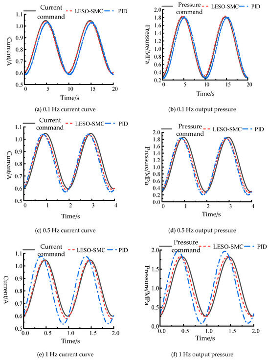
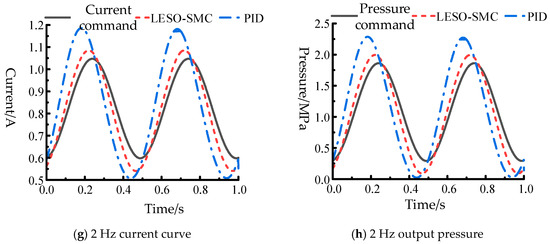
Figure 13.
Results of sinusoidal tracking test.
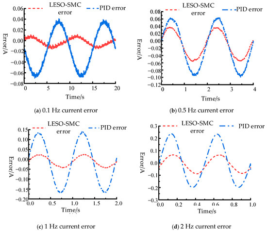
Figure 14.
Test results of current sinusoidal tracking error.
Table 8.
Sinusoidal tracking error table.
As shown in the experimental results of Figure 13 and Figure 14 and Table 8, the tracking performance of LESO-SMC is better than that of PID at 0.1 Hz, 0.5 Hz, 1 Hz, and 2 Hz. The error rates of LESO-SMC at these four frequencies are 0.61%, 3.16%, 2.02%, and 5.79%, respectively, while the error rates of PID at these four frequencies are 3.07%, 5.26%, 12.1%, and 20.09%, respectively.
5.4. Multi-Way Valve Spool Position Control Test
To verify the effectiveness of the spool position control of the proportional pressure-compensated multi-way valve proposed in this paper, step signals and sinusoidal signals were applied to the proportional pressure-compensated multi-way valve, and the changes in spool position were observed.
The fuel supply pressure was set to 3 MPa, the step signal at a given position was set to 0.02 m and 0.06 m. The step signal response results are shown in Figure 15, and the step response performance parameters are listed in Table 9.
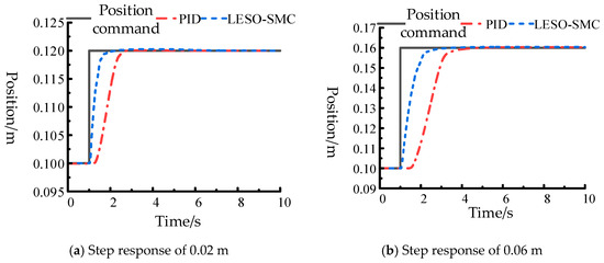
Figure 15.
Position step response results.
Table 9.
Position step response performance parameters.
As shown in Figure 15 and Table 9, the experimental results indicate that LESO-SMC has a better response than PID under both 0.02 m and 0.06 m step signals. The rise time of LESO-SMC is 69.48% and 48.88% faster than that of PID, respectively, and the adjustment time of LESO-SMC is 71.07% and 44.65% faster than that of PID, respectively.
Given a fuel supply pressure of 3 MPa, three different frequency sine signals of 0.5 Hz, 1 Hz, and 2 Hz are provided. The test results and errors of the sine signals are shown in Figure 16, and the specific tracking error data are listed in Table 10.
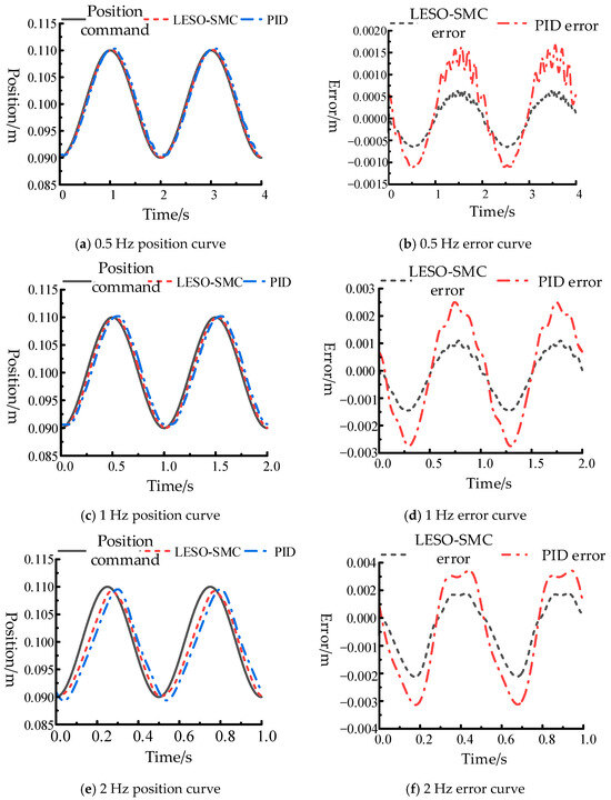
Figure 16.
Position sine tracking and error.
Table 10.
Position sinusoidal tracking error values.
The experimental results shown in Figure 16 and Table 10 indicate that LESO-SMC’s tracking performance at three constant frequencies of 0.5 Hz, 1 Hz, and 2 Hz is superior to that of PID, with the error rates of LESO-SMC being 0.57%, 0.98%, and 1.59%, respectively, and the error rates of PID being 1.49%, 2.29%, and 3.13%, respectively.
6. Conclusions
This paper takes the position control system of the spool in a lead-type proportional multi-way valve as the research object, analyzes the effect of controller parameters on the electromagnetic drive current, and proposes a disturbance observer-based proportional multi-way valve spool position sliding mode control method to compensate for the impact of the nonlinearity and multi-source disturbances of the multi-way valve on the dynamic and static performance of the spool position. The specific conclusions are as follows:
- The impact of the hardware parameters of different controller drive circuitry on the output current is analyzed. Under a constant power supply voltage, the magnitude of the controller’s output current is primarily affected by resistance and the PWM duty cycle. The larger the resistance, the smaller the current; when the PWM duty cycle is less than 0.5, almost no current is present, and, when the duty cycle is greater than 0.5, the current has a linear relationship with the duty cycle; the current ripple is mainly affected by the PWM frequency and inductance. The higher the PWM frequency, the smaller the current ripple, and, the larger the inductance, the smaller the current ripple.
- A sliding mode control method for the spool position of a proportional multi-way valve based on disturbance observation is proposed. A linear extended state observer is used to observe the variations in nonlinear factors such as hydrodynamic forces and friction, combined with sliding mode control, to compensate for the impact of internal and external disturbances on the control accuracy of the multi-way valve spool position, thereby improving the overall valve control performance.
- The step response capability and control accuracy of the solenoid valve core position in the electro-hydraulic proportional multi-way valve is improved. The step response time of the pilot proportional reducing pressure valve is reduced by 18.18% to 44.44%, the control accuracy of the pilot pressure is improved by 39.92% to 83.3%, the step response time of the solenoid valve core position in the electro-hydraulic proportional multi-way valve is reduced by 48.88% to 69.48%, and the control accuracy of the valve core position is improved by 49.2% to 61.74%. Overall, the dynamic and static characteristics of the entire valve are enhanced.
This paper mainly focuses on the position control performance of electro-hydraulic proportional multi-way valves, and we will continue to study the reliability of proportional multi-way valves in the future. Additionally, exploration will be conducted on algorithms for the higher performance of proportional multi-way valves used in construction machinery, further enhancing the performance of proportional multi-way valves. The research results of this paper will contribute to the enhancement of intelligence in proportional multi-way valves for construction machinery.
Author Contributions
Conceptualization, J.F.; Methodology, P.C.; Software, Y.J. and P.C.; Formal analysis, Y.J.; Investigation, L.W.; Resources, P.C.; Data curation, Y.J.; Writing—original draft, J.F.; Writing—review & editing, J.F. and K.Z.; Supervision, W.G. and C.A.; Project administration, W.G.; Funding acquisition, W.G. All authors have read and agreed to the published version of the manuscript.
Funding
This research was funded by the National Natural Science Foundation of China (grant nos. 52205060, 52275069, and U22A20178) and the Open Fund of the National Key Laboratory (GZKF-202423).
Data Availability Statement
The original contributions presented in this study are included in the article. Further inquiries can be directed to the corresponding author(s).
Conflicts of Interest
Author Junxue Feng was employed by the company Beizi (Beijing) Testing Technology Development Co., Ltd. Author Lizhong Wei was employed by the company Nanjing Chenguang Group Co., Ltd. The remaining authors declare that the research was conducted in the absence of any commercial or financial relationships that could be construed as a potential conflict of interest.
Correction Statement
This article has been republished with a minor correction to the Funding statement. This change does not affect the scientific content of the article.
References
- Zhang, G.; Zhang, K.; Shen, W.; Xu, G.; Lin, Y.-J. Intelligent fault diagnosis of multi-way directional valves in hydraulic systems using digital twin and deep learning approaches. Mech. Syst. Signal Process. 2025, 230, 112579. [Google Scholar] [CrossRef]
- Yang, M.; Lian, K.; Luo, S.; Yu, C. Simulation analysis and optimization of pilot type electro-hydraulic proportional directional valve based on multi field coupling. Flow Meas. Instrum. 2024, 100, 102726. [Google Scholar] [CrossRef]
- Li, J.; Peng, C.; Guo, Q.; Wang, Z. Study on flow field characteristics of micro-flow control valve based on fluid-thermal-solid coupling. Arab. J. Sci. Eng. 2024, 50, 8813–8830. [Google Scholar] [CrossRef]
- Wang, H.; Cao, C.; Zhao, J.; Yu, M.; Zhang, Y. Research on dynamic characteristics of a novel high-frequency water hydraulic proportional flow valve. Flow Meas. Instrum. 2025, 104, 102893. [Google Scholar] [CrossRef]
- Liu, X.-Q.; Chai, C.-T.; Ji, H.; Wang, C.; Liu, F.; Xiao, Y.; Cong, W.; Fei, L.; Yao, X. Eroded orifice flow characteristics and bionic anti-erosion of a hydraulic servo spool valve. Flow Meas. Instrum. 2025, 104, 102896. [Google Scholar] [CrossRef]
- Wang, C.; Hou, Y.; Xie, H.; Yang, S.; Wei, Z. Research and improvements on key characteristics of pilot-assisted counterbalance valve used in hydraulic luffing system. Flow Meas. Instrum. 2025, 102, 102819. [Google Scholar] [CrossRef]
- Lyu, F.; Cao, C.; Zhao, D.; Li, C.; Su, J.; Zhao, X.; Jia, X. Vibration characteristics analysis of high-pressure long-distance dense paste pipeline transporting with hydraulic active check valve. Alex. Eng. J. 2023, 71, 669–677. [Google Scholar] [CrossRef]
- Guo, C. Analysis of pressure regulating characteristics of safety valve in hydraulic system of offshore oil production equipment. Ain Shams Eng. J. 2022, 13, 101738. [Google Scholar] [CrossRef]
- Chen, Q.P.; Ji, H.; Xing, H.H.; Zhao, H.K. Experimental study on thermal deformation and clamping force characteristics of hydraulic spool valve. Eng. Fail. Anal. 2021, 129, 105698. [Google Scholar] [CrossRef]
- Xie, H.; Wang, C.; Yang, H. Research on back-pressure compensation characteristics of a pilot-assisted load control valve applied in overrunning load hydraulic systems. Flow Meas. Instrum. 2021, 82, 102048. [Google Scholar] [CrossRef]
- Chen, L.; Jin, B.; Zhang, C.; Guo, Q. State feedback spool position control with integral compensation for servo proportional valve. Inst. Mech. Eng. Part C-J. Mech. Eng. Sci. 2023, 237, 4946–4956. [Google Scholar] [CrossRef]
- Ma, X.; Zhang, X.; Wang, W.; Su, Z.; Zhang, W. Sliding mode variable structure control for servo system of valve controlled hydraulic actuator. In Proceedings of the 2018 IEEE 8th International Conference on Underwater System Technology: Theory and Applications (USYS), Wuhan, China, 1–3 December 2018. [Google Scholar]
- Gao, Q. An Improved PWM Control for Landing Velocity Reduction and Dynamic Performance Preservation in High Speed Solenoid Valve During Excitation Stage. Int. J. Appl. Electromagn. Mech. 2025, 77, 79–93. [Google Scholar] [CrossRef]
- Tobias, G.; Amadeus, L.; Adrian, T.; Matthias, B.; Wolfgang, K. Hybrid Control of Hydraulic Directionalvalves: Integrating Physics-based and Data-driven Models for Enhanced Accuracy and Efficiency. Instrum. Syst. Autom. Soc. 2025, 157, 280–292. [Google Scholar]
- Yang, X.; Zhang, B.; Wu, D.; Liu, Y. Fast switching and dynamic characteristics preservation of water hydraulic high-speed on-off valve using pressure-adaptive multistage voltage and sliding mode control. Mechatronics 2025, 110, 103384. [Google Scholar] [CrossRef]
- Deptuła, A.; Stosiak, M.; Cieślicki, R.; Karpenko, M.; Urbanowicz, K.; Skačkauskas, P.; Deptuła, A.M. Application of the Methodology of Multi-Valued Logic Trees with Weighting Factors in the Optimization of a Proportional Valve. Axioms 2023, 12, 8. [Google Scholar] [CrossRef]
- Stosiak, M.; Karpenko, M.; Deptuła, A.; Urbanowicz, K.; Skačkauskas, P.; Cieślicki, R.; Deptuła, A.M. Modelling and Experimental Verification of the Interactionina Hydraulic Directional Control Valve Spool Pair. Appl. Sci. 2023, 13, 458. [Google Scholar] [CrossRef]
- Feng, H.; Ma, W.; Yin, C.B.; Cao, D. Trajectory Control of Electro-hydraulic Position Servo System Using Improved PSO-PID Controller. Autom. Constr. 2021, 127, 103722. [Google Scholar] [CrossRef]
- Wang, C.; Ji, X.; Zhang, Z.; Zhao, B.; Quan, L.; Plummer, A. Tracking Differentiator Based Back-stepping Control for Valve-controlled Hydraulic Actuator System. ISA Trans. 2022, 119, 208–220. [Google Scholar] [CrossRef]
- Sun, C.G.; Dong, X.X.; Wang, M.J.; Li, J. Sliding Mode Control of Electro-Hydraulic Position Servo System Based on Adaptive Reaching Law. Appl. Sci. 2022, 12, 6897. [Google Scholar] [CrossRef]
- Ba, K.X.; Liu, N.; She, J.B.; Wang, Y.; Ma, G.; Yu, B.; Kong, X. Matrix-sensitivity-based Active Disturbance Rejection Control for Hydraulic Servo Positioning Systems with Friction Compensation. Mechatronics 2025, 110, 103378. [Google Scholar] [CrossRef]
- Tao, X.F.; Liu, K.L.; Yang, J.; Chen, Y.; Chen, J.; Zhu, H. Sliding Mode Backstepping Control of Excavator Bucket Trajectory Synovial in Particle Swarm Optimization Algorithm and Neural Network Disturbance Observer. Actuators 2025, 14, 9. [Google Scholar] [CrossRef]
- Zhang, H.; Zhao, J.Y.; Wang, Y.F.; Zhang, Z.; Ding, H.; Man, J. Electro-hydraulic Position Servo System Based on Sliding Mode Active Disturbance Rejection Compound Control. Proc. Inst. Mech. Eng. Part C-J. Mech. Eng. Sci. 2022, 236, 2089–2098. [Google Scholar]
- Zhang, D.Y.; Liu, S.Y.; Chen, Y.; Gu, C.-C. Neural Direct Adaptive Active Disturbance Rejection Controller for Electro-hydraulic Servo System. Int. J. Control. Autom. Syst. 2022, 20, 2402–2412. [Google Scholar] [CrossRef]
- Zhuang, H.X.; Sun, Q.L.; Chen, Z.Q. Sliding Mode Control for Electro-hydraulic Proportional Directional Valve-controlled Position Tracking System Based on An Extended State Observer. Asian J. Control. 2021, 23, 1855–1869. [Google Scholar] [CrossRef]
- Yu, B.; Li, H.S.; Ma, G.L.; Liu, X.; Chen, C.; Zheng, B.; Ba, K.; Kong, X. Design and Matching Control Strategy of Electro-hydraulic Load-sensitive Hydraulic Power Unit for Legged Robots. Energy 2024, 313, 133730. [Google Scholar] [CrossRef]
- Mou, Q.R.; Liu, X.C.; Wang, Z.Y.; Qiu, Z.; Qiao, W.; Yao, J.; Zhang, P.; Jiao, Z. Energy Efficiency Mapping-based Dual-loop Anti-disturbance Control for Active Load-sensitive Drive system. Chin. J. Aeronaut. 2025. [Google Scholar] [CrossRef]


Disclaimer/Publisher’s Note: The statements, opinions and data contained in all publications are solely those of the individual author(s) and contributor(s) and not of MDPI and/or the editor(s). MDPI and/or the editor(s) disclaim responsibility for any injury to people or property resulting from any ideas, methods, instructions or products referred to in the content. |
© 2025 by the authors. Licensee MDPI, Basel, Switzerland. This article is an open access article distributed under the terms and conditions of the Creative Commons Attribution (CC BY) license (https://creativecommons.org/licenses/by/4.0/).