Abstract
Pallet-type end-effectors robots are widely used for airport baggage handling, because of their better adaptability to different types of baggage. A novel attitude-variable high acceleration motion planning method is presented for improving the handling efficiency, which is to move a pallet with non-fixed baggage as fast as possible under a given path, such that the baggage does not slip at any time. Firstly, the motion state model, which focuses on the friction force between the pallet and baggage during handling, is established. The influence of handling attitude on maximum handling acceleration is analyzed, which is verified by a real robot system made up of an IRB-6700 robot and a pallet. Then, a high acceleration motion planning method is proposed by changing the pallet attitude to avoid relative sliding. Finally, three numerical simulations are implemented to verify the proposed motion planning method. The results show that this method can at least improve handling efficiency by 17.64% in linear motion and up to 34.55% in curved motion compared with the horizontal fixed-attitude handling.
1. Introduction
The transportation of passenger baggage is an important part of airport business [1,2]. After the baggage checks in, there are two key tasks in the terminal: sorting and handling. Sorting refers to allocating the baggage to designated slots or carousels through the sorting system [3,4]. Handling refers to moving the baggage from the designated slots or carousels to the baggage-trailer or Air-Mode Cargo Containers (AKE) of the corresponding flight. Compared with sorting, the handling work is still in the manual stage in many airports [5], and it brings great security risks to the staff [6].
To improve handling efficiency, several semi-automatic handling methods with different types of end-effectors have been adopted by airports [7]. Among them, Srivastava et al. [8] combined the recognition technology based on voltage ID mapping with robot technology, thereby enhancing the sorting and recognition capabilities of baggage. Hentschel [9] summarized and prospected the handling methods of airport logistics, and indicated that robots with end effectors have a huge application space in baggage handling. Zhai [10] designed an underactuated end-effector for grabbing baggage, achieving over 90% of baggage grabbing and handling. In Amsterdam Airport [11], a pallet-type end-effector robot is utilized to pick up baggage from slots and stack it onto AKE. Compared with grabbing, handling with a pallet-type end-effector has better adaptability for different baggage [12], and it can avoid the risk of damage or detachment due to excessive grab force.
The essence of handling efficiency is the robot’s time-optimal motion planning [13,14]. And the non-fixed handling of the object has been visualized as the waiter motion problem [14,15,16]. Obviously, using the constraint trajectory planning method under deep learning is a feasible method [17], but the friction force is the key factor to ensure that the object and the pallet do not have relative slip [18]. The friction force is determined by the friction coefficient between the pallet and the object. The estimation of the friction coefficient is affected by illumination, surface roughness, temperature, etc., so it is difficult to estimate accurately by using deep learning [19,20]. Therefore, previous studies have been carried out under the condition that the friction coefficient of the object is known. Brei et al. [21] proposed a framework named Wrench Analysis for Inertial Transport using Reachability (WAITR). The framework uses reachability analysis to construct over-approximations of the contact torque applied to unsecured objects, which captures uncertainties in the manipulator dynamics, the object dynamics, and contact parameters such as the friction coefficient. Gattringer et al. [22] used an optimized continuous excitation trajectory for parameter identification to build a reliable robot dynamic model. Then, the multiple shooting method is utilized to optimize the path parameters and wrist angles when the pallet moves with four non-fixed cups. Gattringer et al. [23,24] utilized the B-spline curve to parameterize the expected path during the cup handling process. The slippage of the cup and the limitations of the robot system are considered to solve the time-optimal and energy-optimal trajectories by using the multiple shooting method. Simulation and experiment are carried out by moving the cup with water on the pallet, which verifies that attitude-variable motion planning can improve the handling efficiency. Zhang [25] used a time-optimal trajectory planning algorithm based on reachability analysis to solve the robot’s time-optimal trajectory that satisfies the dynamic constraints during the non-fixed handling process.
Previous studies on the waiter motion problem have mostly focused on the application of light-load handling on experimental scenarios, lack practical adaptation, and rely heavily on the known information of objects. Inspired by the waiter motion problem, this paper solves the applicability in heavy-load handling scenarios, and focuses on the pallet-type baggage handling in busy airports and proposes a novel attitude-variable motion planning method to improve the handling efficiency. The main contributions are as follows:
(1) The motion state model of pallet-type baggage handling is established for the typical plane motion and spatial motion, which focuses on the friction force between the pallet and baggage. Then, the influence of pallet attitude on the maximum handling acceleration and stability is discussed.
(2) A novel attitude-variable high acceleration motion planning method for the pallet-type airport baggage handling robot is presented under a given path. This method considers the velocity and acceleration limits of the pallet in Cartesian space and introduces the safety boundary to avoid relative sliding. On this basis, considering the time optimization, the attitude change of the pallet is minimized to reduce the energy loss. Three typical baggage handling paths are selected to verify the planning method. The results show that the method can improve the handling efficiency while ensuring stability.
After the motion state model is established, verified, and discussed in Section 2, and experiments verified in Section 3, the novel attitude-variable high acceleration motion planning method is presented in Section 4. In Section 5, three numerical simulations are implemented, and Section 6 draws the conclusion.
2. Motion State Model Establishment
2.1. Pallet-Type Handling Robot System
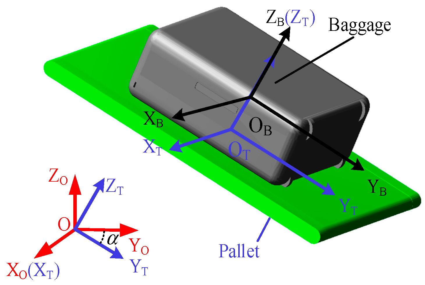
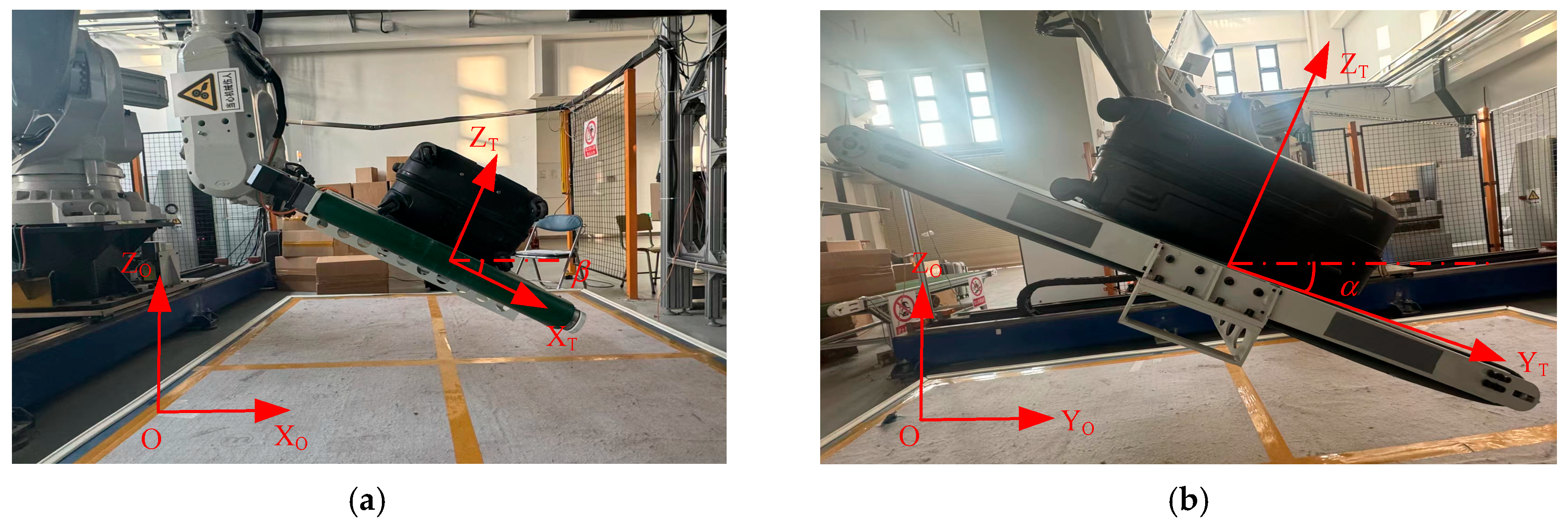
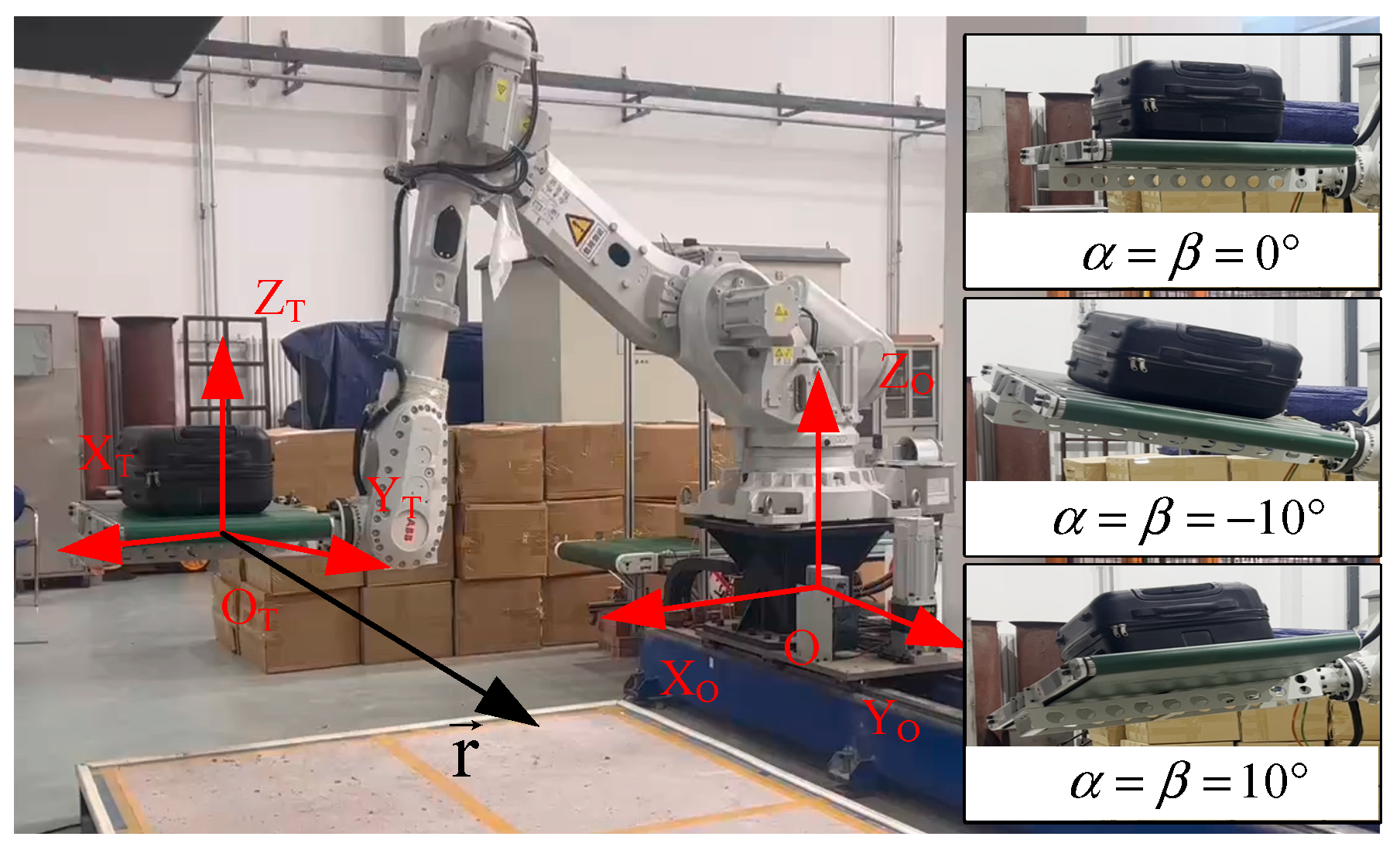
As shown in Figure 1a, the robot is configured with a pallet-type end-effector, which has a small conveyor to translate baggage from slots to the baggage trailer. The baggage handling process is conducted with the assistance of a vision system. It is notable that the baggage handling considered in this paper refers to the baggage moving process and does not involve the picking up and stowing. For the convenience of system modeling and analysis, the coordinate systems between the ground, robot, pallet, and baggage are established as shown in Figure 1b, where {O} refers to the base coordinate system and {OT} refers to the pallet coordinate system and is located in the center of the upper surface of the pallet. The baggage coordinate system is named as {OB}, and it is established at the center of mass of the baggage.
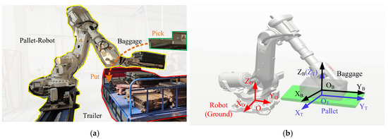
Figure 1.
Pallet-type airport baggage handling robot system: (a) a typical work station and (b) the coordinate systems.
The pallet-type airport baggage handling can be treated as a waiter motion problem, i.e., moving a pallet with non-fixed baggage under a given path. It is notable that slip, twist, and tip over are three types of failure in handling processes. For airport baggage handling, the slip between the baggage and pallet is the main factor that causes baggage to fall off the pallet. Therefore, this paper focuses on only the slip between baggage and pallet, while the twist and tip over are not considered. Because the friction and support forces between the pallet and baggage are the key to maintaining stable handling, establishing the motion state model, which focuses on the friction force during handling, is the foundation of motion planning.
Additionally, in a general case, the rotation of the pallet around the ZT-axis does not affect the friction in the XT-OT-YT plane. Therefore, for simplicity, this paper only considers the effects of the pallet’s rotations around the XT-axis and YT-axis on the stability of baggage handling.
2.2. Plane Motion State Model
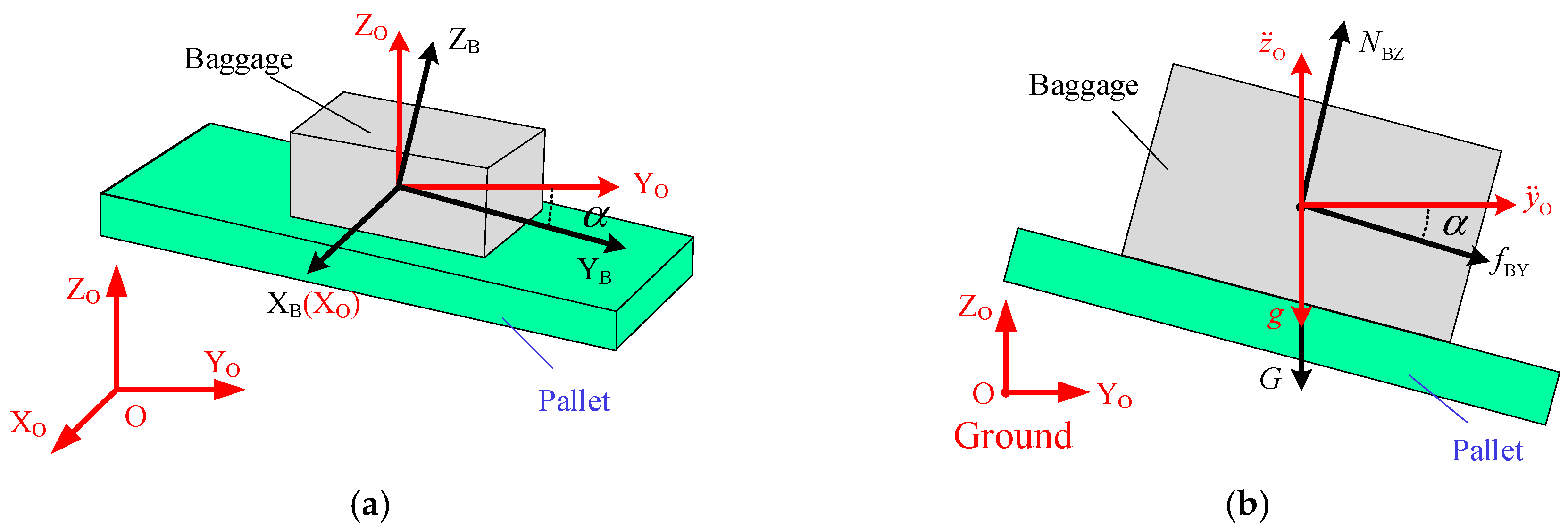
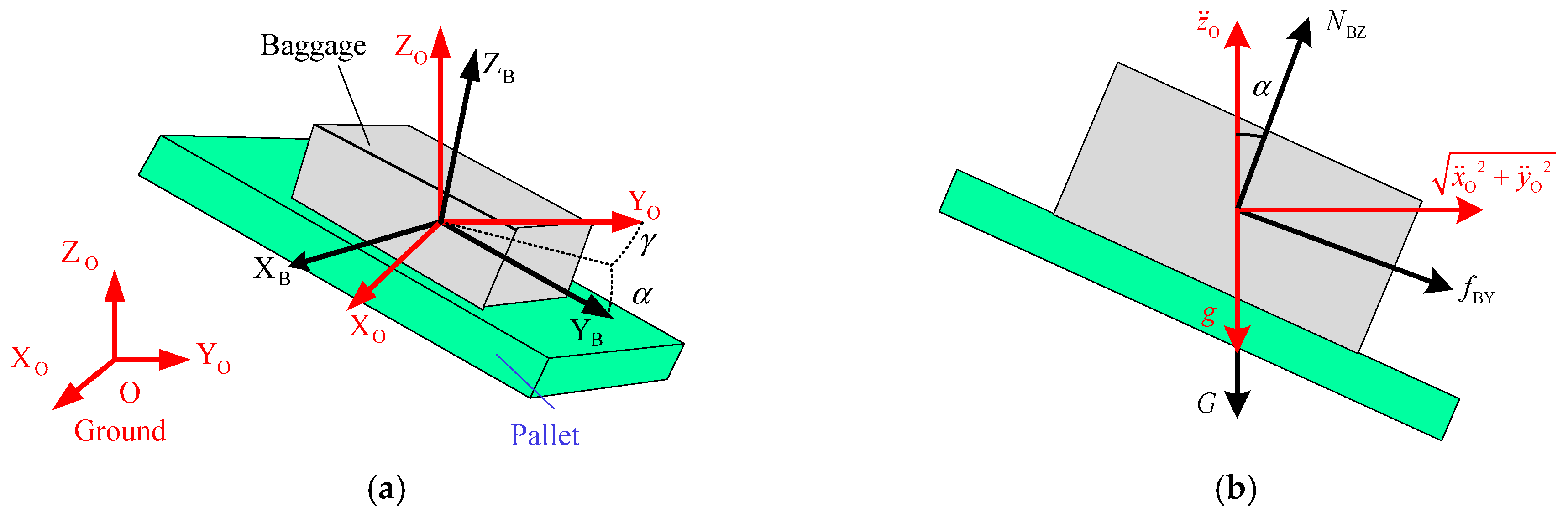
Here, plane motion is the simplest case of baggage handling, which refers to moving parallel to the ZO-O-YO plane. The plane motion state model is used to establish the relationship between friction, support force, and inertia force, which can reflect the influence of pallet attitude on maximum handling acceleration, as shown in Figure 2.
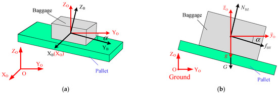
Figure 2.
Plane motion state model: (a) coordinate systems and (b) force and acceleration relationships.
When there is no relative slip, the attitudes of the baggage and pallet are the same. Therefore, the force balance relations for the baggage can be established according to the attitude of the pallet. According to D’Alembert’s principle, the force balance relations for the baggage can be expressed as follows:
where , represent the acceleration of the pallet along the YO-axis and ZO-axis, respectively. is the mass of the baggage. represents the friction exerted on the baggage by the pallet along the YB-axis. NBZ is the support force. is the gravity of the baggage, and g is the gravitational acceleration. is the rotation angle of the pallet around the XO-axis. It is notable that and g are parallel to each other, then the effects of can be treated as the increment of the gravitational acceleration. In other words, for simplicity, we can get an equivalent motion station, i.e., and . When , the pallet moves horizontally along the YO-axis.
When the frictional force reaches its limit, the relationship is obtained as , and gets its maximum value in this case. From Equation (2), can be derived as follows:
By combining Equations (1) and (3), when the angle of the pallet around the XO-axis is , the maximum acceleration of the baggage along the YO-axis can be obtained as Equation (4). Equation (4) can also be treated as the plane motion state model, which reflects the influence of pallet attitude on maximum handling acceleration. When the practical acceleration is out of this range, a relative slip between the pallet and baggage would occur, which would damage the stability of baggage handling.
where is the friction coefficient between the pallet and baggage. Finally, in order to ensure a reliable contact between the pallet and baggage, the support force acting on the baggage should be greater than zero; this constraint can be expressed as follows:
To verify the correctness of the plane motion state model, a simulation model is established in the ADAMS 2020 software, as shown in Figure 3. For the sake of clarity, the main parameters of the baggage are shown in Table 1. In software, the friction is set by creating contact forces between the baggage and the pallet. The friction coefficient is set to 0.4 based on our experience. Then, the slip would be determined by measuring the relative displacement between the baggage and pallet.

Figure 3.
Simulation model in the ADAMS software.

Table 1.
Main parameters of the baggage.
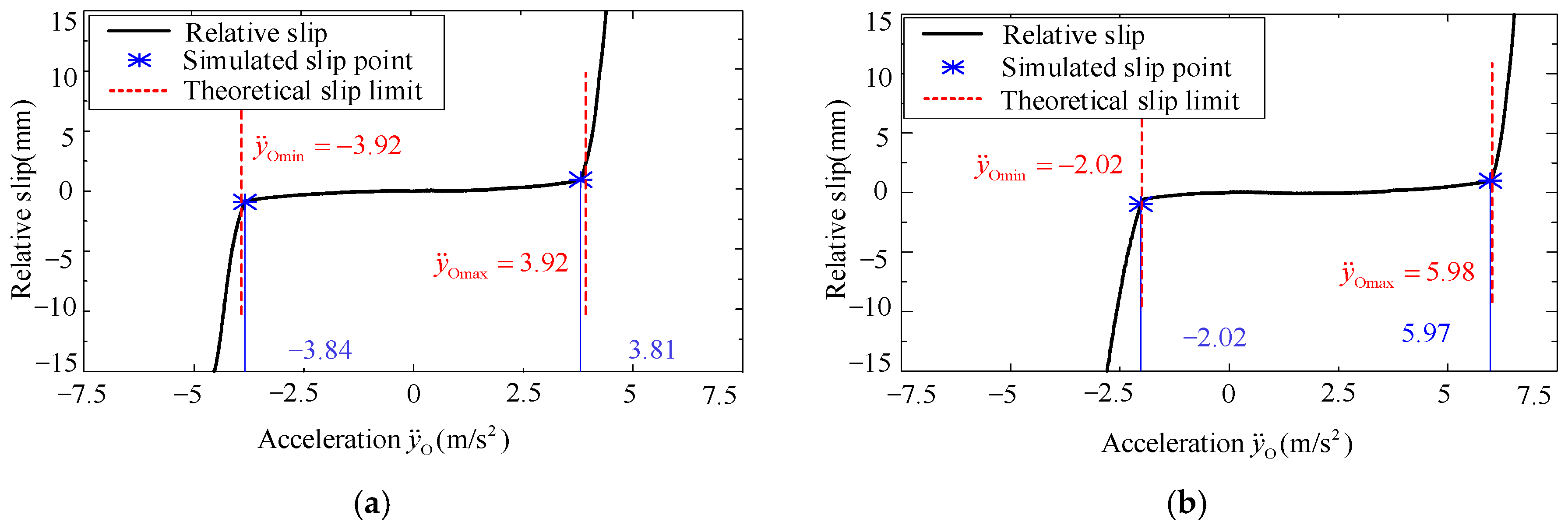
In this simulation, the pallet would conduct a linear motion along the YO-axis. And is sequentially set to and , while would increase or decrease gradually. Figure 4 shows the measured relative slip between baggage and pallet in the simulation. Here, when the measured relative displacement is greater than 0.5 mm, the acceleration would be treated as the maximum value, i.e., the slip point. For the sake of clarity, the maximum accelerations derived by the plane motion state model, i.e., Equation (4), and the simulations are summarized in Table 2. From Figure 4 and Table 2, the simulation data and the theoretical values are well consistent, and the relative errors are all smaller than 3%, which verifies the correctness of the constructed plane motion state model.
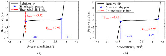
Figure 4.
Relative slip between baggage and pallet in plane linear motion: (a) and (b) .
Table 2.
The maximum accelerations for the plane linear motion.
2.3. Acceleration Boundary Under Plane Motion
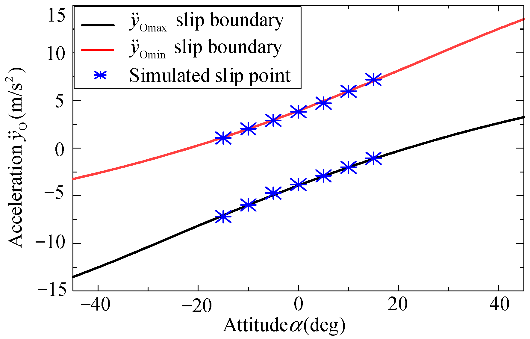
According to Equation (4), the maximum acceleration is a function of . A similar conclusion can be drawn in the above simulation, i.e., the maximum acceleration of the pallet along the YO-axis changes along with . To further analyze the influence of on the maximum acceleration, i.e., acceleration boundary under plane motion, a series of simulations are conducted. The maximum accelerations of the pallet along the YO-axis with different are shown in Figure 5.
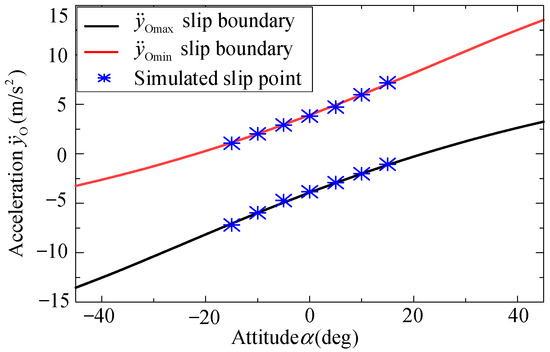
Figure 5.
Acceleration boundary changing with .
In Figure 5, the red line represents the upper boundary of the pallet’s acceleration along the YO-axis, the black line represents the lower boundary of the pallet’s acceleration along the YO-axis, and the blue points represent the slip points when relative slip between the baggage and pallet occurs in the simulations. As increasing, the acceleration range of the pallet that can stably handle baggage will shift upwards, and it will shift downwards when decreased. These results indicate that the handling acceleration can be improved by adjusting , increasing the handling efficiency.
2.4. Spatial Motion State Model
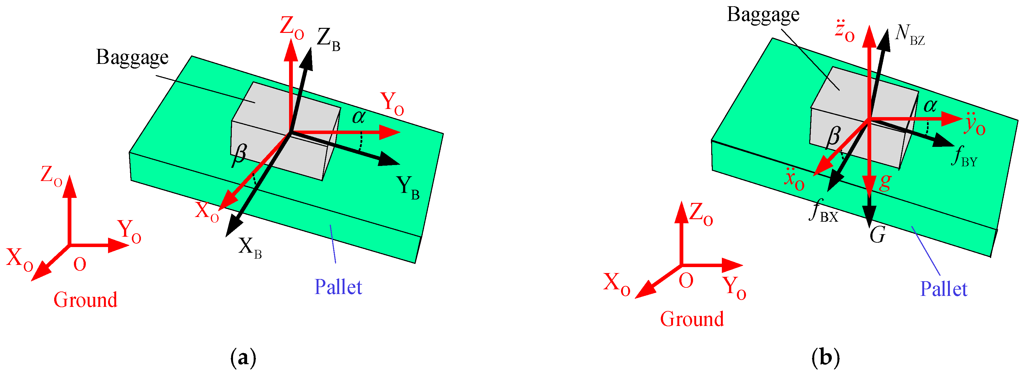
Without loss of generality, the motion state model of the pallet should be extended from plane motion to spatial motion. The coordinate systems, force, and acceleration relationships are shown in Figure 6.

Figure 6.
Spatial motion state model: (a) coordinate systems and (b) force and acceleration relationships.
Compared with plane motion, the spatial motion introduces the rotation around the YO-axis to describe the attitude of the pallet, i.e., β. As mentioned in Section 2.1, the rotation of the pallet around the ZO-axis is neglected. Therefore, if the pallet attitude is expressed by Z-Y-X Euler-angle in base coordinate system {O}, the rotation around ZO-axis is set to . The pallet attitude can be represented as Equation (6).
During the handling or motion process, the support force and friction of the baggage with respect to frame {OB} are expressed as Equations (7) and (8), respectively. The gravity with respect to frame {O} is expressed as Equation (9).
According to D’Alembert’s principle, the force balance relations for baggage can be established as follows:
By combining Equations (7)–(10), the reaction forces, i.e., frictions and support forces acting on the baggage, can be derived as follows:
To avoid a relative slip, the total friction should be less than or equal to the maximum value, i.e., Equation (12).
Then the reaction forces acting on the baggage should meet the constraint condition as follows:
By combining Equations (11) and (13), two constraint equations on the acceleration and support force are derived as follows:
where is the support force.
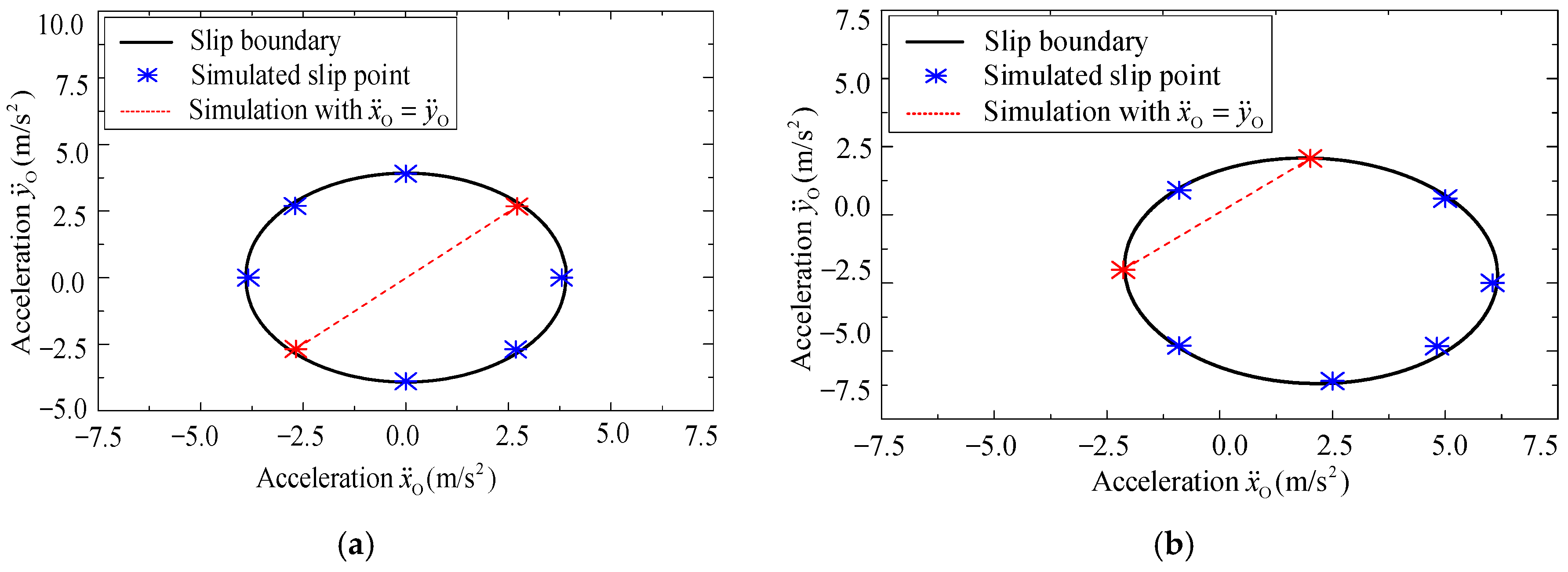
Similarly, to verify the correctness of the spatial motion state model, i.e., Equation (14), numerical simulations are conducted based on the simulation model in the ADAMS software. Here, is set to 0.4, the acceleration of the pallet along the ZO-axis is neglected, i.e., and the acceleration boundary when and are shown in Figure 7a and Figure 7b, respectively.
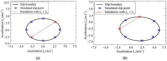
Figure 7.
Acceleration boundary when (a) α = β = 0° and (b) α = β = 10°.
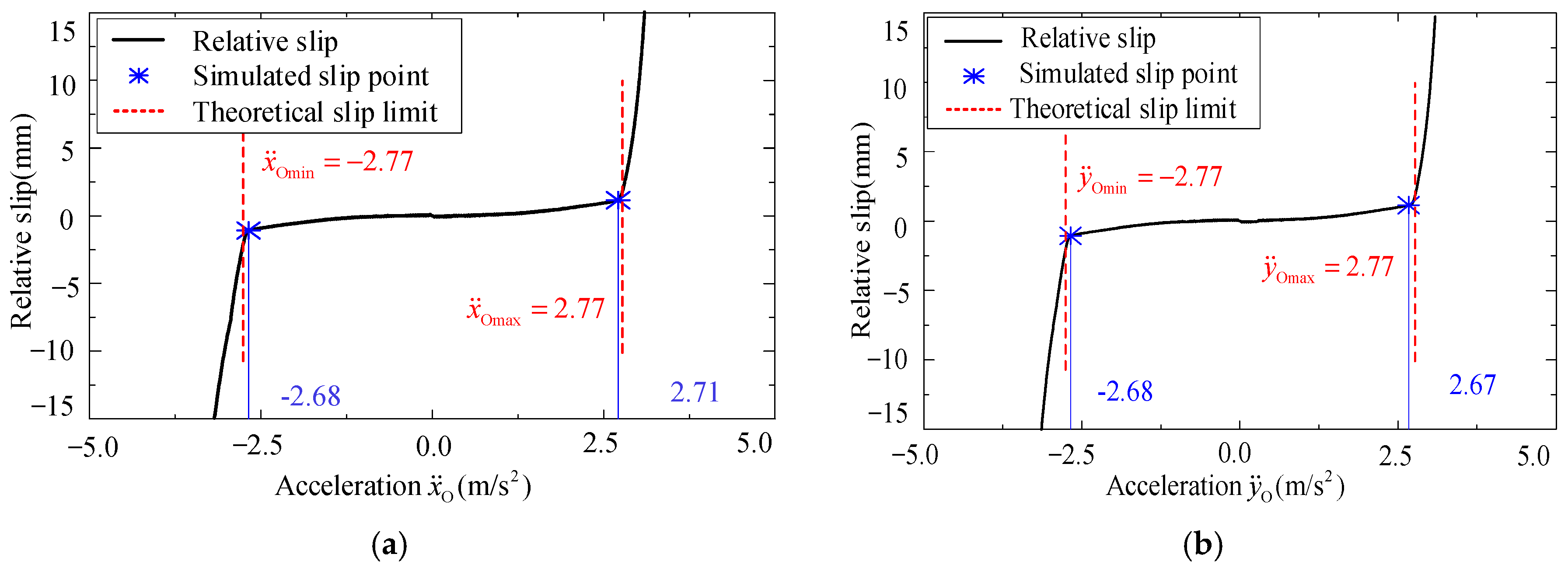
In Figure 7, the black line represents the theoretical slip boundary, i.e., maximum acceleration of the pallet along XO-axis and YO-axis to ensure that no relative slip between the baggage and pallet occurs under different attitudes, while the blue and red dots represent the critical point when relative slip between the pallet and the baggage is observed in the simulation process. The red dotted line is selected for further analysis and verification, which indicates that the pallet moves with the same acceleration along the XO-axis and YO-axis, i.e., . For comparison, two attitudes of pallet, i.e., α = β = 0° and α = β = 10°, would be studied. The changing relationships of the relative slip and acceleration are shown in Figure 8 and Figure 9, respectively.
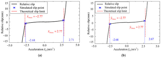
Figure 8.
Relative slip when : (a) and (b) .
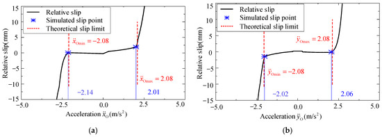
Figure 9.
Relative slip when : (a) and (b) .
For the sake of clarity, the maximum accelerations derived by the spatial motion state model, i.e., Equation (14), and the simulations are summarized in Table 3. From Figure 8, Figure 9, and Table 3, the simulation data and the theoretical values are well consistent, and the relative errors are all smaller than 4%, which verifies the correctness of the constructed spatial motion state model.
Table 3.
The maximum accelerations for the spatial motion.
2.5. Acceleration Boundary Under Spatial Motion
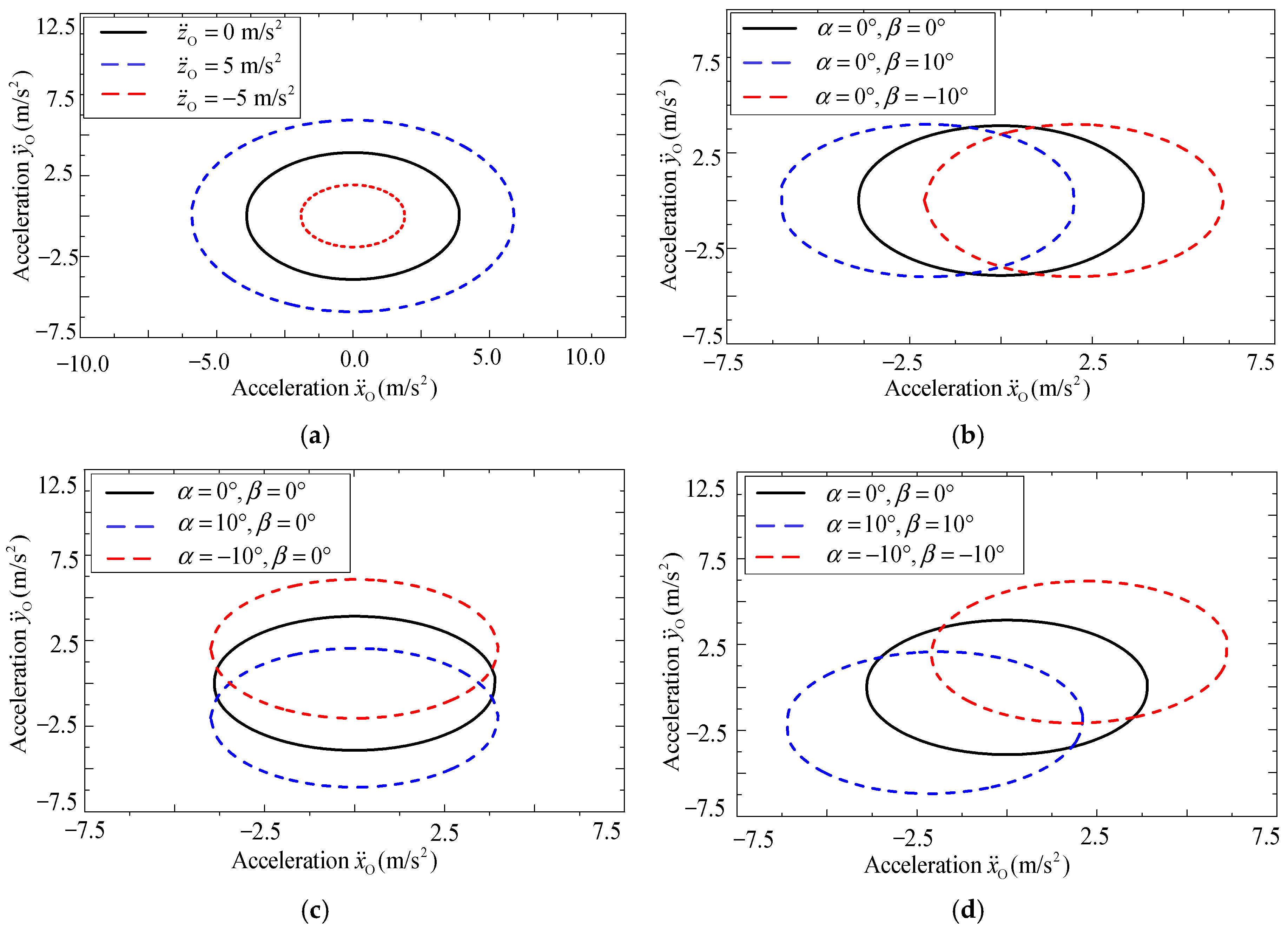
To further explore the influence of , , and on the maximum acceleration, i.e., acceleration boundary under spatial motion, a series of simulations are conducted. Firstly, and are set to , and the acceleration is the only variable. The acceleration boundary along the XO-axis and YO-axis is shown in Figure 10a. From Figure 10a, with the increase in , the maximum acceleration will be greater, and when decreases, the acceleration boundary will also decrease.
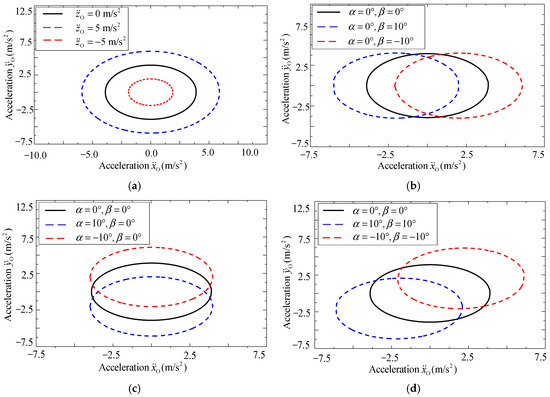
Figure 10.
Acceleration boundary changing with (a) , (b) , (c) and (d) .
3. Verification Experiments
In Section 2, the motion state models are verified and discussed by the simulation model. In order to further verify the availability of the constructed motion state models and simulation model in practical application, a pallet-type robot system based on the IRB-6700 industrial robot is utilized to conduct a practical baggage handling experiment. And the experimental data would be compared with that in the simulations to verify the consistency between the simulation model and the practical baggage handling system. It is notable that the friction coefficient has a significant effect on the stability of the system. For consistency of experimental conditions, the friction coefficient would be measured and taken into the simulation model. In the experiment, the IRB-6700 industrial robot was controlled by the RAPID command in RobotStudio 6.08 software, and the position accuracy of the TCP (Tool Central Point) position motion was 0.1 mm. The TCP position, seed, and acceleration information of the robot are also monitored by RobotStudio 6.08 software, and the signal sampling time is 20 ms.
3.1. Measurement of Friction Coefficient
The friction coefficient would be obtained by measuring the friction angle, as shown in Figure 11a,b. The pallet slowly rotates around the YO-axis and XO-axis, respectively, until the baggage slip occurs. Due to the influence of the controller observation accuracy and the maximum static friction force of the baggage, to improve measurement accuracy, the measurement of friction angle and should be repeated three times, and the mean value will be retained. The results are summarized in Table 4.

Figure 11.
Measurement of the friction angle along (a) YO-axis and (b) XO-axis.
Table 4.
Friction angle between pallet and baggage.
The friction coefficient can be derived as the tangent of the corresponding friction angle. From Table 4, the friction coefficient along the XT-axis is 0.6879, and the friction coefficient along the YT-axis is 0.6892. The relative error is 0.1%, which shows that the friction coefficients along the XT-axis and YT-axis can be treated as the same, and the average value is used as the value of the friction coefficient, i.e., .
It should be pointed out that the friction coefficient is related to the material of the baggage, and it can be predicted based on vision measurement and deep learning technology [19,20]. Limited by the length of this paper, this study only focuses on the slip phenomenon for simplicity, while the friction coefficient is treated as known. Then, the measured friction coefficient would be used in the following experiments and studies.
3.2. Acceleration Boundary Under Different Attitudes
In this experiment, the pallet is gradually accelerated in a fixed direction until relative slip occurs, as shown in Figure 12. Here, is the direction vector of the given linear path. For comparison, three typical attitudes of the pallet, i.e., , , and , would be tested and analyzed. The relative displacement or slip between the baggage and pallet is recorded and judged through the high-speed camera.
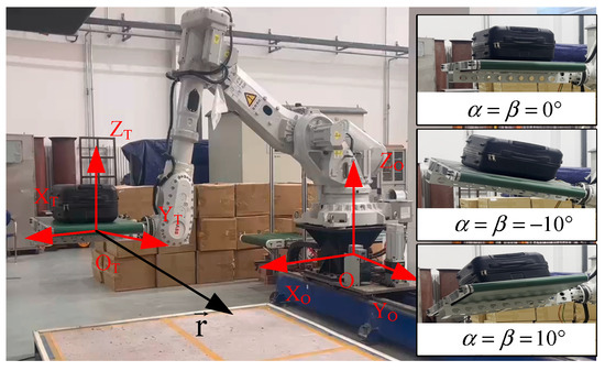
Figure 12.
Motions of the pallet with three typical attitudes.
For three typical attitudes of the pallet, the maximum acceleration, i.e., the experimental slip points, is shown in Figure 13a. Here, the acceleration of the pallet along the direction is denoted as . The brown dots represent the acceleration when the relative slip occurs. For comparison, the same friction coefficient, attitudes, and motion path of the pallet are also brought into the simulation model in the ADAMS software. The simulated and experimental slip points are shown in Figure 13b. The green dots represent the simulated slip points for three attitudes of the pallet, while the brown dots are the experimental slip points. From Figure 13b, when , the relative error between the simulated and experimental values is 0.14%. When , the relative error is 2.24%, and when , the relative error is 0.88%. The experimental and Adams simulation errors are affected by the vibration of the robot during acceleration in the real world, the smoothness of the baggage surface, the mass distribution of baggage, and the air resistance. Although the uncertainty factors affect the error of the experiment and simulation, the relative error of both is less than 3%. The experimental results not only prove that the constructed motion state models are effective in the practical handling process but also show that the simulation model is well consistent with the practical robot system. Therefore, for simplicity and security, the following analysis and verifications will be conducted based on the simulation model.
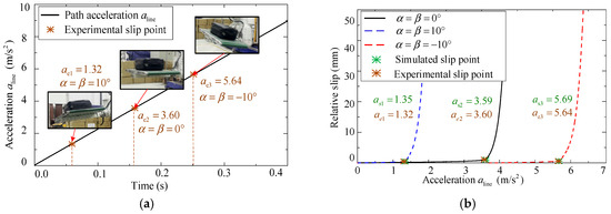
Figure 13.
Slip points in (a) experiments and (b) simulations.
4. Attitude-Variable Motion Planning Method
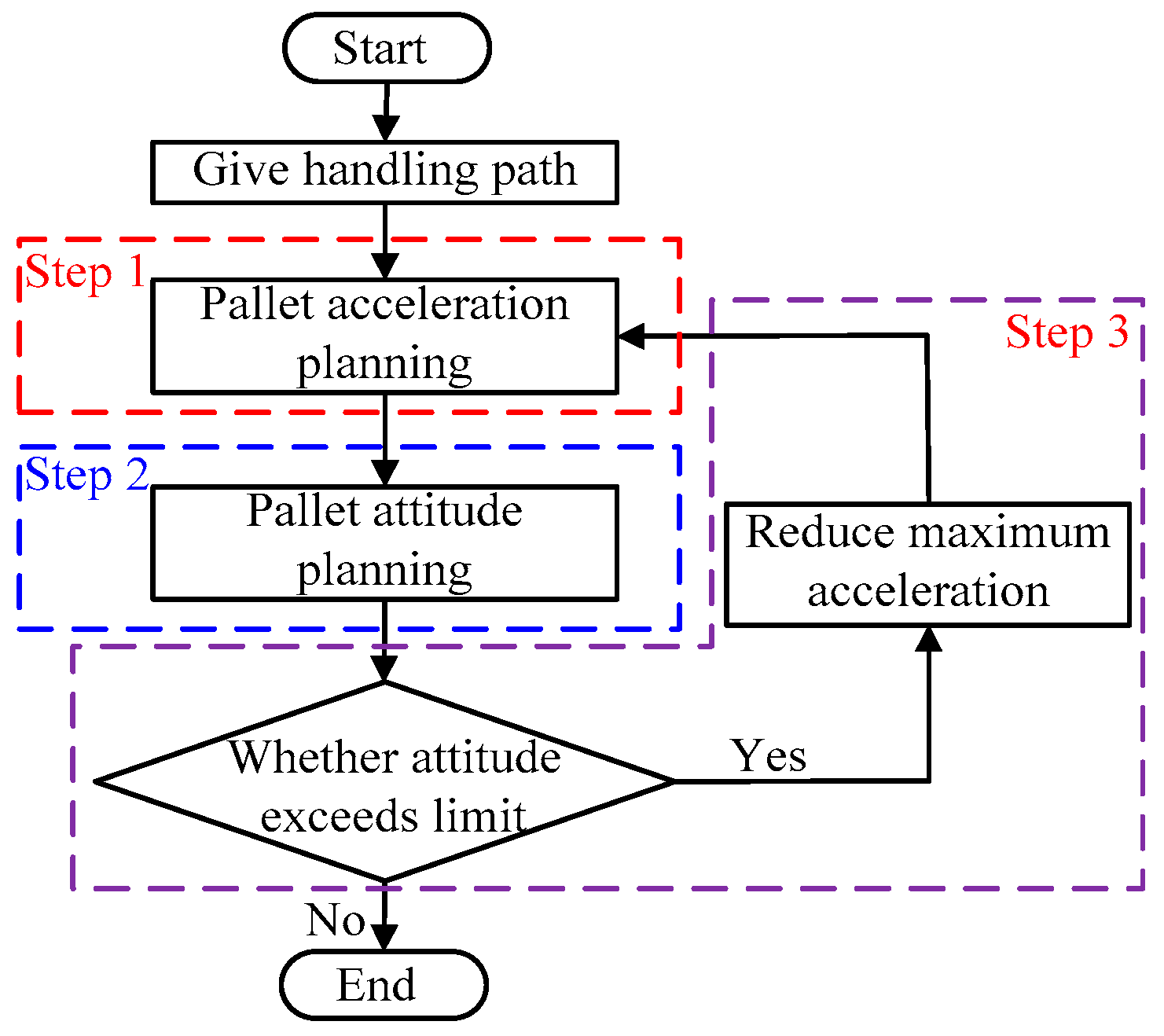
According to the analysis in Section 2, the maximum acceleration can be improved by adjusting the attitude of the pallet. In this section, a novel attitude-variable high acceleration motion planning method is proposed to improve the efficiency of baggage handling, as shown in Figure 14. This method can be divided into three steps.
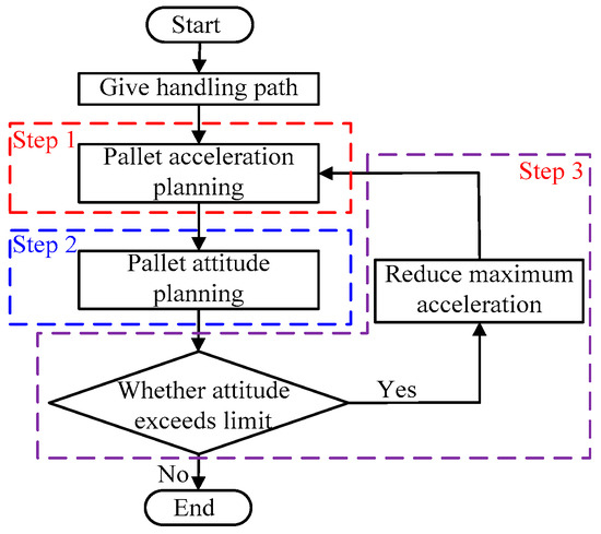
Figure 14.
Flowchart of attitude-variable motion planning.
Firstly, the acceleration definition of the pallet or robot under a given handling path is made. The shortest time of baggage handling is determined according to the maximum acceleration and velocity of the robot TCP, which is generally limited by the handling environment. Secondly, the planned acceleration is taken into the motion state model, i.e., Equations (4) and (14), to obtain the attitude range of the pallet without relative slip. Then, the attitude of the pallet would be planned. Finally, it is determined whether the planned attitude exceeds the limit of the pallet attitude. If the planned attitude function fails to meet the conditions, it is re-planned by reducing the maximum acceleration and velocity of the TCP. For the sake of clarity, the first two main steps will be described in the following sections.
4.1. Acceleration Definition Under Given Path
The given path is denoted as , which can be expressed by a parametric equation, i.e., Equation (15). Then, the total path length L can be calculated by Equation (16).
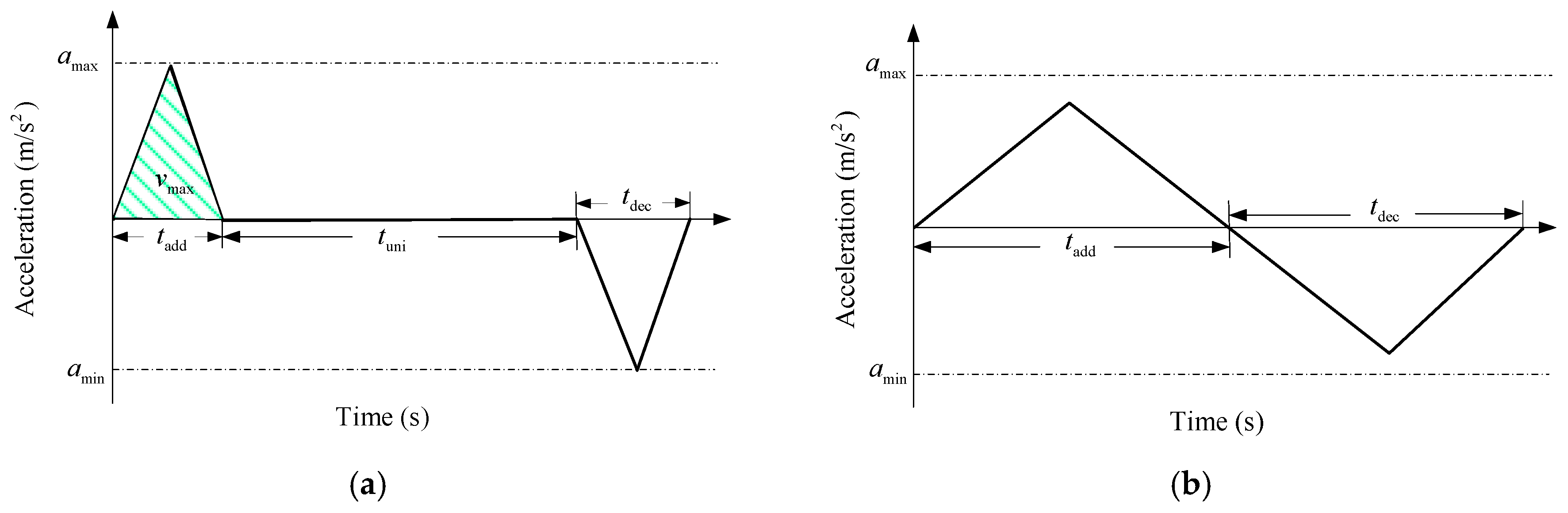
where represents the velocity along the path. If the acceleration along the motion path increases or decreases with constant gradient, the actual acceleration can be obtained according to maximum acceleration and maximum velocity , as shown in Figure 15. It is notable that when , the given path is long enough. The whole motion can be divided into three sub-processes: acceleration, uniform velocity, and deceleration, as shown in Figure 15a. When , the uniform velocity process will not occur, as shown in Figure 15b.
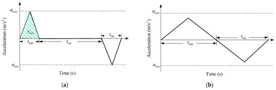
Figure 15.
Pallet acceleration planning (a) with uniform velocity and (b) without uniform velocity.
After the acceleration is defined, the relation function between the path length and time, i.e., L(t), can be derived. Because L(t) should be consistent with Equation (16), a constraint function can be obtained as follows:
where uins is the path parameter corresponding to time t. Finally, the trajectory function can be derived as follows:
where is the minimum total motion time. Then, the acceleration can be expressed as .
4.2. Attitude Planning of the Pallet
If the accelerations along three axes in frame {O}, i.e., , and are obtained in Section 4.1, the feasible attitude of the pallet, i.e., and , can be derived according to the motion state model, i.e., Equation (4) or Equation (14). It is notable that two parameters should be determined by only one equation; in other words, the multi-solution problem exists. In order to solve this problem, an equivalent expression of the attitudes is proposed to convert the pallet spatial motion along the given path to a plane motion, as shown in Figure 16. From Figure 16, the attitude of the pallet is described by two parameters, i.e., and , where is the rotation angle around the ZO-axis, and is rotation angle around the XO-axis. In other words, the attitude of the pallet can be treated as the result of two rotations with respect to frame {O}: rotate around the ZO-axis and then rotate around the updated XO-axis.

Figure 16.
Pallet attitude and acceleration: (a) attitude parameters γ and α and (b) force and acceleration relations in ZB-OB-YB plane.
For the pallet-type baggage handling task, the relative slip between pallet and baggage is in the XB-OB-YB plane. And when the sum vector of accelerations and is in the ZB-OB-YB plane, the relative slip can be avoided by adjusting only the attitude angle . Therefore, for simplicity, the sum vector of accelerations and is assumed to be in the ZB-OB-YB plane. Under this assumption, the attitude angle can be derived as Equation (19). In this equivalent motion state, there is no force along the XB-axis is applied to the baggage. The acceleration and force relationships between the baggage and pallet can be analyzed in the ZB-OB-YB plane, as shown in Figure 16b.
From Figure 16b, the force balance relations for the baggage can be derived as follows:
Additionally, when the friction between the baggage and the pallet reaches the limit, we can obtain the following:
To sum up, when , , and are obtained in Section 4.1, the attitude angle can be derived from Equation (19), while the minimum attitude angle should be derived by combining Equations (20) and (21). Then, with the motion of the pallet, and would be functions of time, i.e., and . Here, it is notable that the value of should be set to the minimum, i.e., the above derived for energy saving. However, in order to increase the security redundancy, the practical attitude angle should be appropriately increased, i.e., . Here, is the security margin, which is generally determined by trial and error. Finally, all the discrete points should be interpolated to ensure the continuity and smoothness of the pallet’s motion. The pseudocode of the planning method is shown as Algorithm 1.
| Algorithm 1 Attitude-variable high acceleration motion planning method |
| Input: |
| Output: , |
| 1: L; // Calculate the length of the path according to Equation (16) |
| 2: if (L) then // Determine whether the path length has a uniform motion time |
| 3: tmin = tadd + tuni + tdec; // Calculate the minimum time to move along the path |
| 4: else tmin = tadd + tdec; |
| 5: end if |
| 6: ; // Transformed the parameter path into time variable path using the minimum time according to Equations (17) and (18) |
| 7: ; // Take the second derivative of the trajectory to get the acceleration of TCP |
| 8: ; // Solve the TCP attitude rotating around ZB-axis according to Equation (19) |
| 9: ; // Solve the TCP attitude rotating around XB-axis according to Equations (20) and (21) |
| 10: ; // Introduce security margin on the basis of attitude planning |
| 11: return , , ; |
5. Numerical Simulations and Discussion
In order to verify the proposed attitude-variable high acceleration motion planning method, three numerical simulations are conducted based on the simulation model in the ADAMS software, i.e., plane linear motion, spatial linear motion, and spatial curved motion. For consistency, the friction coefficient is set as 0.688. The maximum acceleration and velocity of the TCP are and , respectively.
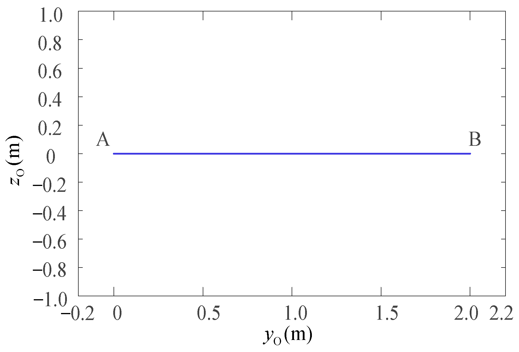
5.1. Plane Linear Motion
Plane linear motion means that the pallet moves in a single direction along the YO-axis, as shown by the blue line A to B in Figure 17. The given path can be expressed as follows:
where , while and are constant values. Then, according to derivation in Section 4.1, the acceleration along the YO-axis can be defined as shown in Figure 18.
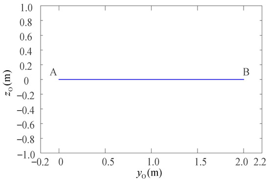
Figure 17.
The plane linear motion.
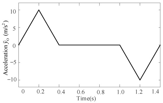
Figure 18.
Acceleration definition for the plane linear motion.
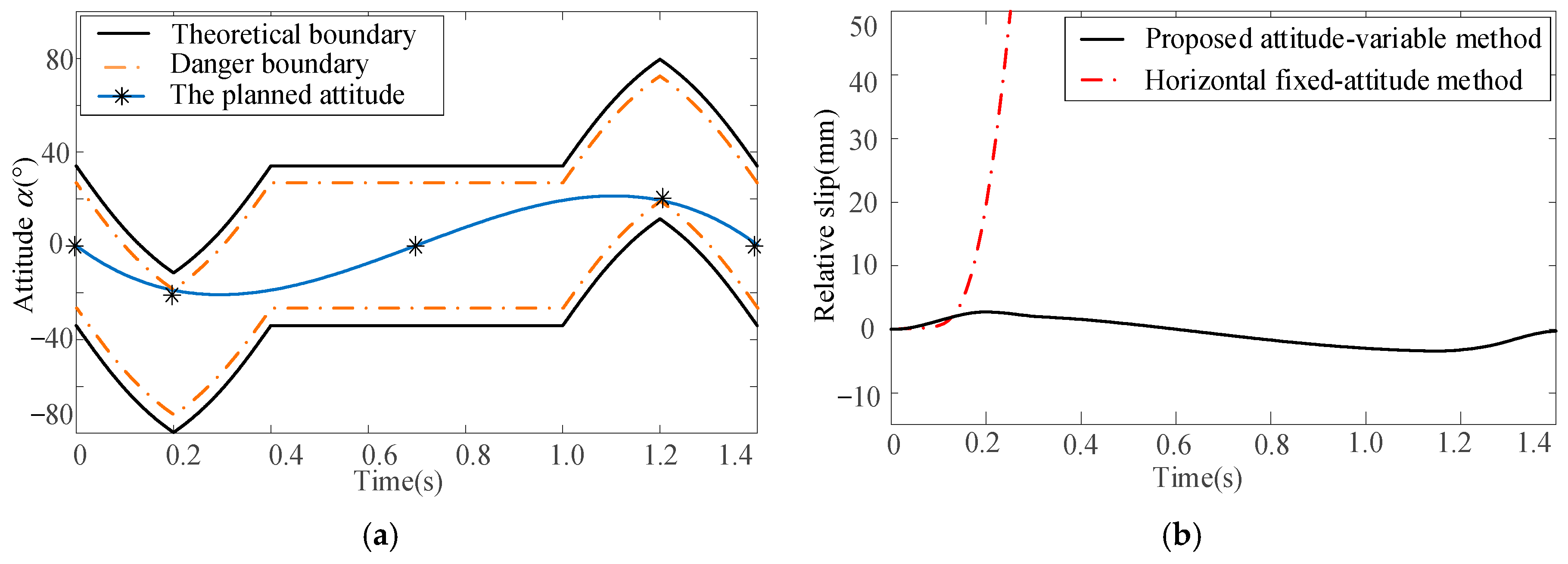
For this plane linear motion, only one attitude angle , i.e., the rotation around the XO-axis, needs to be planned. According to the acceleration and Equation (4), the minimum attitude angle , i.e., the theoretical boundary, can be derived as shown in Figure 19a. In order to increase the security redundancy, the security margin is introduced. Then, the danger boundary can be derived by increasing the theoretical boundary by . Additionally, limited by the mechanical structure, the rotation around the XO-axis is constrained as shown by the two red dotted lines in Figure 19a. Finally, the planned is derived as shown by the blue curve in Figure 19a. For comparison, the motion parameters derived by the proposed attitude-variable motion planning method and horizontal fixed-attitude method are brought into the simulation model. The relative slips between baggage and pallet are shown in Figure 19b, where the black curve represents the relative slip of the proposed attitude-variable method, while the red curve represents that of the horizontal fixed-attitude method.
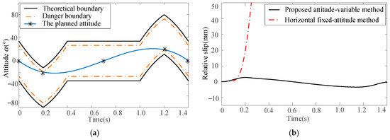
Figure 19.
Attitude planning and simulation verification for plane linear motion: (a) attitude α planning and (b) simulation results.
From Figure 19b, for the horizontal fixed-attitude motion planning method, when the acceleration reaches the theoretical boundary, i.e., time is 0.2 s, a relative slip between the baggage and pallet occurs. In contrast, by smoothly adjusting the attitude of the pallet, the proposed attitude-variable motion planning method can effectively avoid relative slip. This result shows that the proposed attitude-variable planning method can improve the stability of baggage handling under high acceleration.
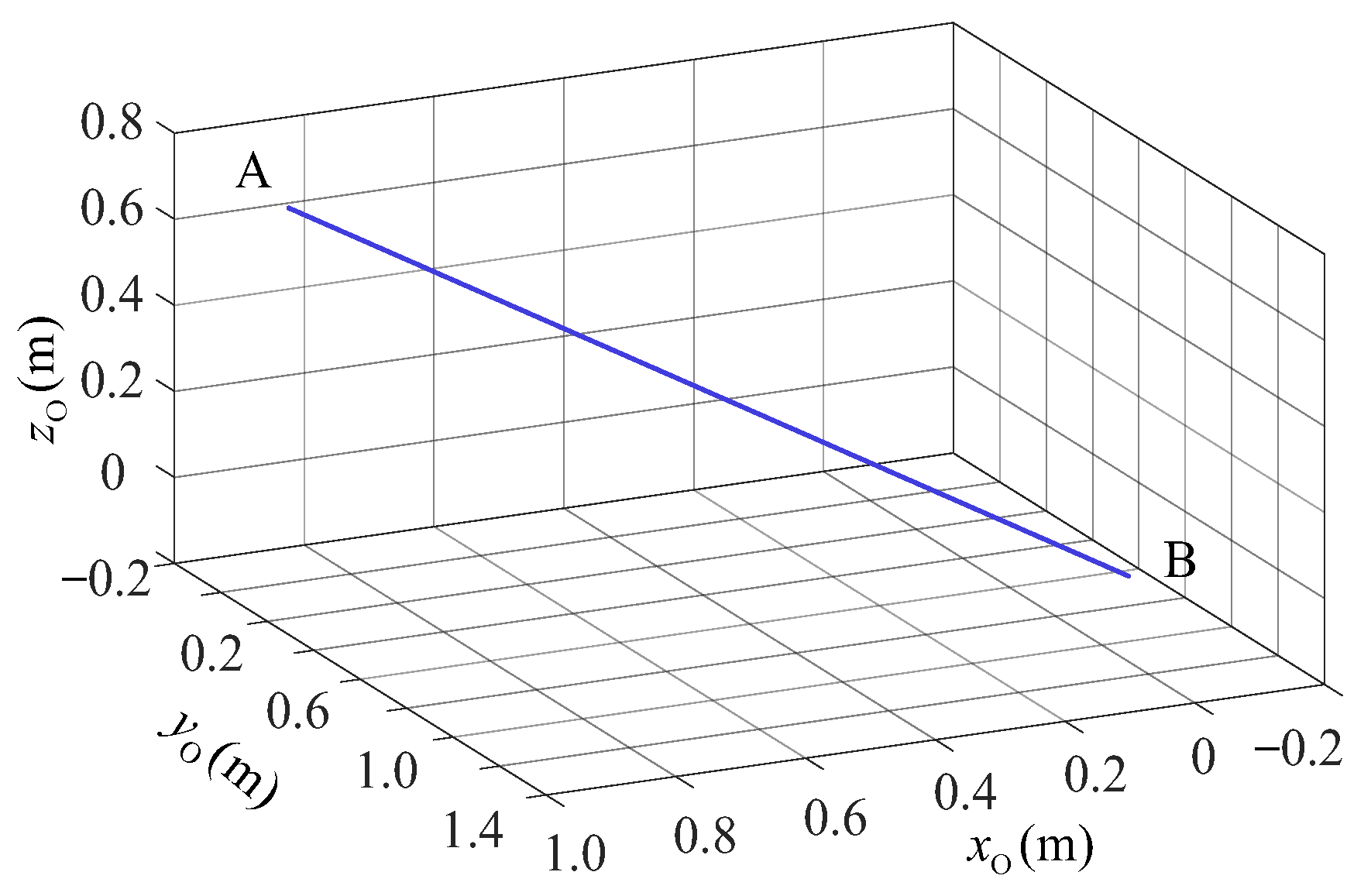
5.2. Spatial Linear Motion
Without loss of generality, the motion of the pallet is extended from plane motion to spatial linear motion, as shown by the blue line A to B in Figure 20. The given path can be expressed as follows:
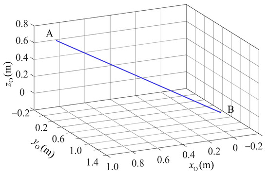
Figure 20.
The spatial linear motion.
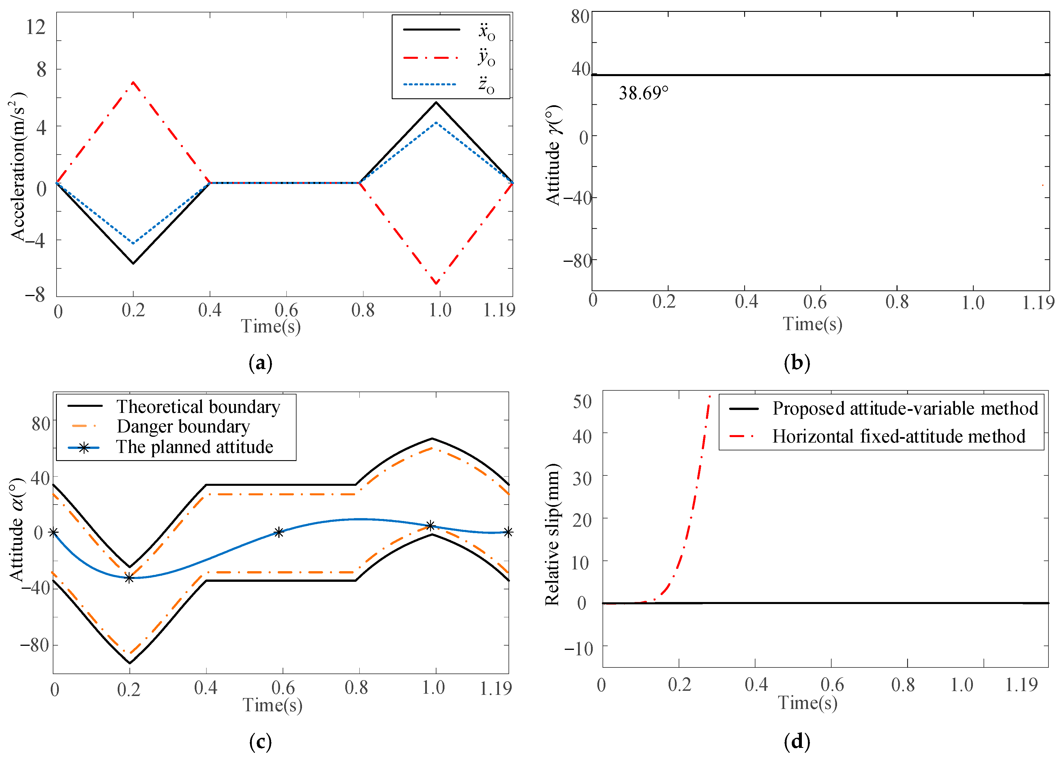
Then, according to derivation in Section 4.1, the accelerations along three coordinate axes can be defined as shown in Figure 21a. The two planned attitudes are shown in Figure 21b and c, respectively, and the relative slips between baggage and pallet are shown in Figure 21d. From Figure 21d, for the horizontal fixed-attitude motion planning method, when the acceleration reaches the theoretical boundary, i.e., time is 0.16 s, a relative slip between the baggage and pallet occurs. By smoothly adjusting two equivalent attitudes of the pallet, the proposed attitude-variable motion planning method can effectively avoid relative slip. This result also shows the feasibility and effectiveness of the method presented in this paper to convert the attitude planning of spatial motion into that of an equivalent plane motion.
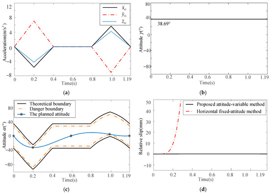
Figure 21.
Attitude planning and simulation verification: (a) acceleration definition, (b) attitude γ planning, (c) attitude α planning, and (d) simulation results.
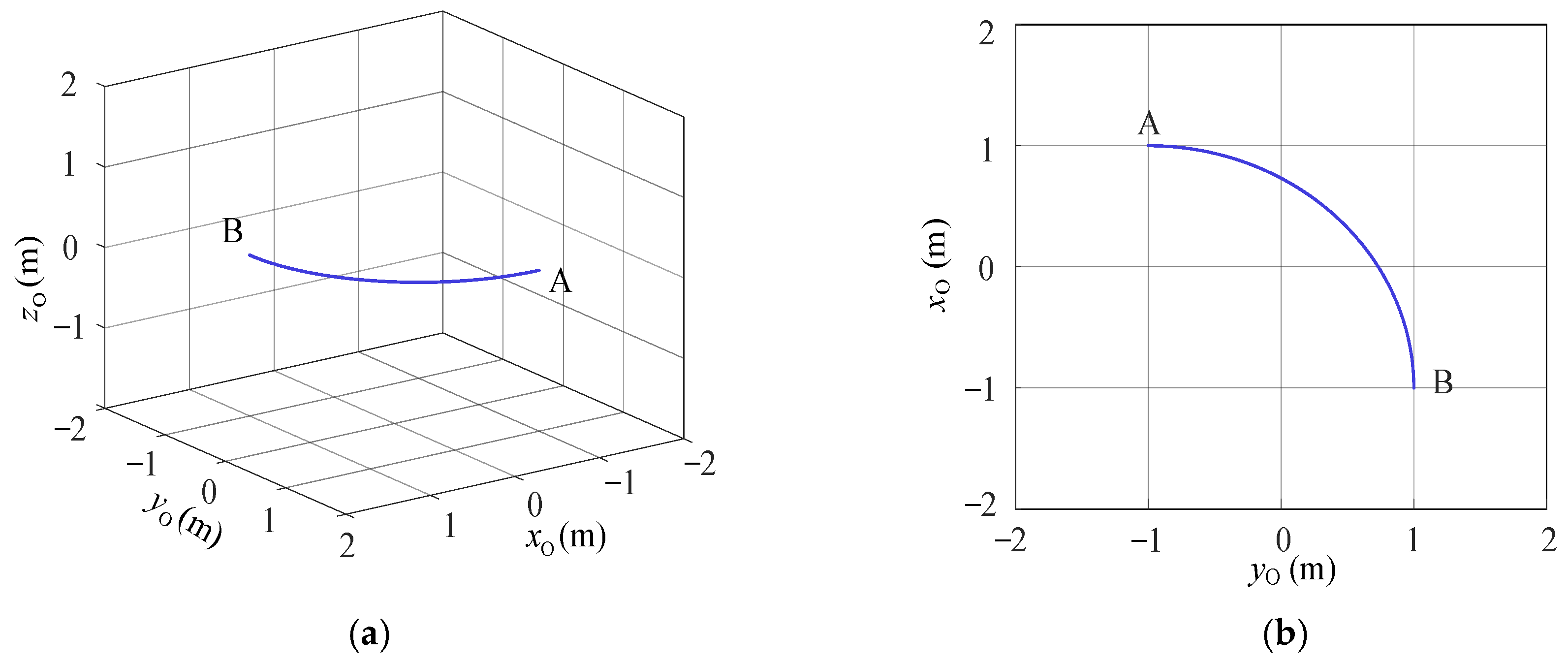
5.3. Spatial Curved Motion
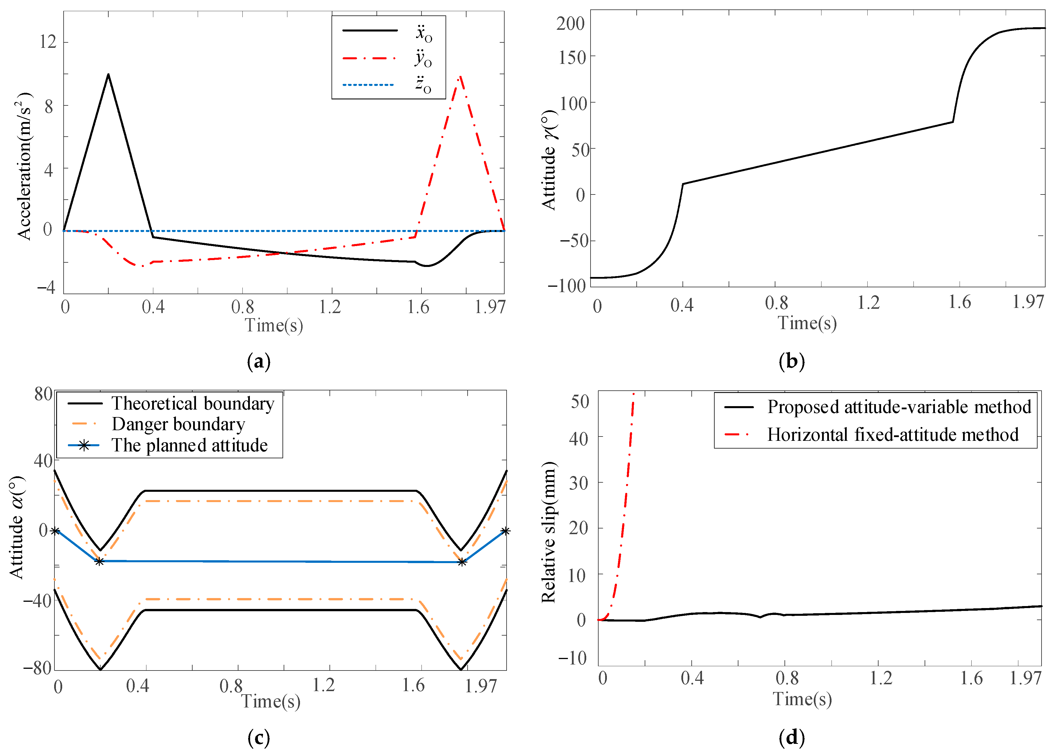
In order to further verify the proposed attitude-variable motion planning method, a spatial curved path is analyzed in this section, as shown in Figure 22. The given path can be expressed by Equation (24). The accelerations along three coordinate axes are defined as shown in Figure 23a. The two planned attitudes are shown in Figure 23b and c, respectively, while the relative slips between baggage and pallet are shown in Figure 23d.
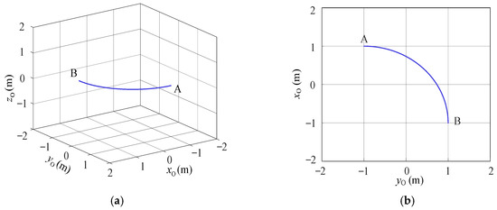
Figure 22.
Spatial curved motion: (a) axonometric view and (b) top view.
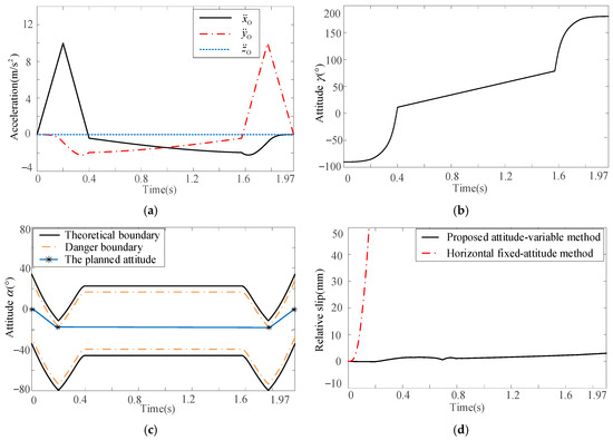
Figure 23.
Attitude planning and simulation verification for spatial curved motion: (a) acceleration planning, (b) attitude γ planning, (c) attitude α planning, and (d) simulation results.
From Figure 23d, for the horizontal fixed-attitude motion planning method, when the acceleration reaches the theoretical boundary, i.e., time is 0.05 s, a relative slip between the baggage and pallet occurs. By smoothly adjusting two equivalent attitudes of the pallet, the proposed attitude-variable motion planning method can effectively avoid relative slip, improving the stability of baggage handling under high acceleration. This result shows that the proposed attitude-variable planning method is effective for a general spatial motion.
5.4. Results and Discussion
To more intuitively demonstrate the advantage of the proposed attitude-variable high acceleration motion planning method, the total motion time of the proposed attitude-variable motion planning method and the horizontal fixed-attitude method for the above three paths are compared, and the results are summarized in Table 5. It is notable that for the horizontal fixed-attitude method, the maximum acceleration of the TCP is set to based on the experience, to avoid relative slip between the baggage and pallet.
Table 5.
Comparison of handling efficiency.
From Table 5, for the plane linear motion, the handling efficiency of the proposed attitude-variable motion planning method is increased by 17.64% compared with that of the horizontal fixed-attitude method. For the spatial linear motion, the handling efficiency has increased by 30.40%. And for the spatial curved motion, the handling efficiency has increased by 34.55%. These results indicate that the proposed attitude-variable high acceleration motion planning method for the pallet-type airport baggage handling robot in this paper can effectively improve the efficiency.
Although deploying robots in real-world airports for validation is difficult, several brief sets of data, as shown in Table 6, are organized to clarify the practical benefits of the proposed method in baggage handling. The data in Table 6, taken from part of the baggage carousel at Guangzhou Baiyun Airport’s T2 terminal, show the number of baggage on a single flight and the time it takes to load them manually. To compare the efficiency of the proposed method, it is assumed that the handling efficiency of the robot under horizontal handling attitude is the same as that of a man. And the efficiency improvement under the plane linear motion is assumed as the overall efficiency improvement of handling.
Table 6.
Airport baggage handling data.
According to the data presented in Table 6, the average processing time for baggage is recorded at 16.9 s. For narrow-body aircraft, the average baggage load amounts to 60 pieces, while wide-body aircraft carry an average of 237 pieces. With an efficiency improvement of 17.64%, there has been a notable reduction in loading times: The average loading time for narrow-body aircraft has decreased by 2 min and 58 s, and for wide-body aircraft, it has decreased by 11 min and 46 s. These reductions are instrumental in minimizing ground operational time for flights.
6. Conclusions
The handling of rigid baggage by pallet-type end-effector robots was formulated as a waiter motion problem and solved using an attitude-variable motion planning method. The formulation mainly accounts for the friction force between the pallet and baggage under the unilateral contact conditions. Particularly crucial is the modeling, verification analysis of the motion state model. Experimental results demonstrate the accuracy of the proposed motion state and simulation models. Numerical simulations further reveal that the acceleration range can be improved by adjusting the pallet’s attitude during general spatial motion. Based on the motion models, a novel attitude-variable high acceleration motion planning method is proposed to improve the efficiency of baggage handling, considering acceleration and velocity limits. It is worth noting that this method transforms the problem of solving attitude spatial boundaries into planar boundaries.
To verify the effectiveness of the proposed motion planning method, three typical baggage handling motions are selected for numerical simulations. The simulation results are compared with results obtained with horizontal fixed-attitude handling. The handling efficiency of the proposed method is increased by 17.64% for plane linear motion, 30.40% for spatial linear motion, and 34.55% for spatial curved motion. Based on this, a simple flight baggage loading statistic is used for efficiency benefit analysis; the results clearly show that the method can effectively improve the stability of baggage handling under high acceleration and shorten the waiting time of the aircraft in the baggage loading link. To promote the engineering application of the pallet-type airport baggage handling robot system and the proposed motion planning method, our further work will focus on the adaptive measuring of the friction coefficient and robust control strategy by considering multiple uncertainties.
Author Contributions
Modeling, X.W. and J.L.; methodology, X.W. and W.Z.; simulation and validation, X.W., J.L. and W.Z.; experiment, J.L. and W.Z.; data analysis, X.W., J.L. and W.Z.; writing—original draft preparation, J.L.; writing—review and editing, W.Z and X.W. All authors have read and agreed to the published version of the manuscript.
Funding
This research was supported by the Fundamental Research Funds for the Central Universities (No. 3122023031).
Data Availability Statement
All research data are supported for sharing. Please do not hesitate to email xh_wang@cauc.edu.cn.
Conflicts of Interest
The authors declare no conflicts of interest.
References
- Liu, D.; Tian, Y.; Xu, Z.; Jian, G. Handling occlusion in prohibited item detection from X-ray images. Neural Comput. Appl. 2022, 34, 20285–20298. [Google Scholar] [CrossRef]
- Ruf, C.; Schiffels, S.; Kolisch, R.; Frey, M.M. A data-driven approach for baggage handling operations at airports. Transp. Sci. 2022, 56, 1179–1195. [Google Scholar] [CrossRef]
- Yang, X.; Feng, R.; Xu, P.; Wang, X.; Qi, M. Internet-of-things-augmented dynamic route planning approach to the airport baggage handling system. Comput. Ind. Eng. 2023, 175, 108802. [Google Scholar] [CrossRef]
- Gupta, V.; Mitra, R.; Koenig, F.; Kumar, M.; Tiwari, M.K. Predictive maintenance of baggage handling conveyors using IoT. Comput. Ind. Eng. 2023, 177, 109033. [Google Scholar] [CrossRef]
- Dall’Olio, G.; Kolisch, R. Formation and routing of worker teams for airport ground handling operations: A branch-and-price-and-check approach. Transp. Sci. 2023, 75, 1231–1251. [Google Scholar] [CrossRef]
- Tafazzol, A.; Aref, S.; Mardani, M.; Haddad, O.; Parnianpour, M. Epidemiological and biomechanical evaluation of airline baggage handling. Int. J. Occup. Saf. Ergon. 2016, 22, 218–227. [Google Scholar] [CrossRef] [PubMed]
- Beumer Group. Baggage Handling Technology. Available online: https://www.beumergroup.com/pd/baggage-handling-technology (accessed on 20 April 2025).
- Srivastava, H.; Abhishek, K.; Harish, K.; Tripathi, A. A design and development of baggage sorting robotic system at the airport. Evergreen 2022, 9, 86–92. [Google Scholar] [CrossRef]
- Hentschel, B. Airport logistics: Innovative solutions for baggage-handling. LogForum 2015, 1, 1–8. [Google Scholar]
- Zhai, Y. Research and Design of the End Effector of the Intelligent Airport Baggage Handling Robot. Master’s Thesis, Jilin University, Changchun, China, 2021. [Google Scholar]
- Vanderlande. Amsterdam Airport. Available online: https://www.vanderlande.com/references/amsterdam-airport-schiphol/ (accessed on 20 April 2025).
- Gábor, C.; Akos, N.; István, V. Near time-optimal path tracking method for waiter motion problem. IFAC-PapersOnLine 2017, 50, 4929–4934. [Google Scholar]
- Wei, B.; Liu, C.; Zhang, X.; Zheng, K.; Cao, Z.; Chen, Z. Smooth and Time-Optimal Trajectory Planning for Robots Using Improved Carnivorous Plant Algorithm. Machines 2024, 12, 802. [Google Scholar] [CrossRef]
- Luo, D.; Huang, X.; Miao, M.; Gao, X. Optimal Trajectory Planning for Wheeled Robots (OTPWR): A Globally and Dynamically Optimal Trajectory Planning Method for Wheeled Mobile Robots. Machines 2024, 12, 668. [Google Scholar] [CrossRef]
- Nagy, Á.; Csorvási, G.; Vajk, I. Path tracking algorithms for non-convex waiter motion problem. Period. Polytech. Electr. Eng. Comput. Sci. 2018, 62, 16–23. [Google Scholar] [CrossRef]
- Heins, A.; Schoellig, A. Keep it upright: Model predictive control for nonprehensile object transportation with obstacle avoidance on a mobile manipulator. IEEE Robot. Autom. Lett. 2023, 8, 7986–7993. [Google Scholar] [CrossRef]
- Lai, J.; Wu, Z.; Ren, Z.; Tan, Q.; Xiao, H. Optimal navigation of an automatic guided vehicle with obstacle constraints: A broad learning-based approach. IEEE Trans. Emerg. Top. Comput. Intell. 2024, 1–15. [Google Scholar] [CrossRef]
- Subburaman, R.; Selvaggio, M.; Ruggiero, F. A non-prehensile object transportation framework with adaptive tilting based on quadratic programming. IEEE Robot. Autom. Lett. 2023, 8, 3581–3588. [Google Scholar] [CrossRef]
- Brandao, M.; Hashimoto, K.; Takanishi, A. Friction from vision: A study of algorithmic and human performance with consequences for robot perception and teleoperation. In Proceedings of the 2016 IEEE-RAS 16th International Conference on Humanoid Robots (Humanoids), Cancun, Mexico, 15–17 November 2016; pp. 428–435. [Google Scholar]
- Le, T.; Verdoja, F.; Abu-Dakka, F.; Kyrki, V. Probabilistic surface friction estimation based on visual and haptic measurements. IEEE Robot. Autom. Lett. 2021, 6, 2838–2845. [Google Scholar] [CrossRef]
- Brei, Z.; Michaux, B.; Holmes, P.; Vasudevan, R. Serving Time: Real-time, safe motion planning and control for manipulation of unsecured objects. IEEE Robot. Autom. Lett. 2024, 9, 2383–2390. [Google Scholar] [CrossRef]
- Gattringer, H.; Mueller, A.; Oberherber, M.; Kaserer, D. Time-optimal path following for robotic manipulation of loosely placed objects: Modeling and experiment. IFAC-PapersOnLine 2020, 53, 8450–8455. [Google Scholar] [CrossRef]
- Gattringer, H.; Mueller, A.; Oberherber, M.; Kaserer, D. Time-optimal robotic manipulation on a predefined path of loosely placed objects: Modeling and experiment. Mechatronics 2022, 84, 102753. [Google Scholar] [CrossRef]
- Gattringer, H.; Müller, A.; Weitzhofer, S.; Schörgenhumer, M. Point to point time optimal handling of unmounted rigid objects and liquid-filled containers. Mech. Mach. Theory 2023, 184, 105286. [Google Scholar] [CrossRef]
- Zhang, Z.; Guo, F.; Tang, Q.; Chen, J. Handling robot non-fixed high-velocity handling method. In Journal of Physics: Conference Series; IOP Publishing: Bristol, UK, 2023; Volume 2492, p. 012025. [Google Scholar]


Disclaimer/Publisher’s Note: The statements, opinions and data contained in all publications are solely those of the individual author(s) and contributor(s) and not of MDPI and/or the editor(s). MDPI and/or the editor(s) disclaim responsibility for any injury to people or property resulting from any ideas, methods, instructions or products referred to in the content. |
© 2025 by the authors. Licensee MDPI, Basel, Switzerland. This article is an open access article distributed under the terms and conditions of the Creative Commons Attribution (CC BY) license (https://creativecommons.org/licenses/by/4.0/).