Abstract
For the new type of CFRP (Carbon Fiber Reinforced Plastic) thin-walled components with a large size and weak rigid structure, due to the integration of geometric features and the reduction in the amount of parts, the assembly size transmission chain is short compared to traditional metal assembly structures. In addition, the manufacturing errors and layer parameters of large composite parts in different regions are different, and they also have a lower forming accuracy. For the current assembly method that mainly concerns geometric dimensions and tolerances, it is difficult to support precise analysis and accurate geometric error forms for different local and global regions. As a result, in practical engineering, the forced method of applying a local clamping force is inevitably adopted to passively reduce and compensate for assembly errors. However, uneven stress distribution and possible internal damage occur. To avoid the assembly quality problems caused by forced clamping operations, the research status on the optimization of forced clamping process parameters before assembly, the flexible position–force adjustment of fixtures during assembly, and gap compensation and strengthening before assembly completion was analyzed systematically. The relevant key technologies, such as force limit setting, geometric gap reduction, stress/damage evolution prediction, the reverse optimization of clamping process parameters, and precise stress/damage measurement, are proposed and resolved in this paper. With the specific implementation solutions, geometric and mechanical assembly status coupling analysis, active control, and a collaborative guarantee could be achieved. Finally, future research work is proposed, i.e., dynamic evolution behavior modeling and the equalization of the induction and control of physical assembly states.
1. Introduction
1.1. Assembly Characteristics of Large and Integrated Composite Structures
The construction of major aerospace products is an important symbol of scientific and technological development, national defense strength, and the industrialization level. Regarding the key performance indicators of modern aerospace products, such as the lifespan, stealth, maneuverability, etc., they have all shown a leap in advancement of orders of magnitude [1], and the assembly accuracy requirements have generally reached the sub-millimeter level. Considering the service reliability, CFRP parts or structures have been widely adopted in the main load-bearing structure, as shown in Figure 1 [2,3]. The composite fuselage of a Boeing 787 has a total length of 55.5 m but is only joined at the end of seven tube sections, with a reduction of about 50,000 fasteners. For the Airbus 350-XWB aircraft, integrated composite wing ribs were adopted instead of segmented metal wing ribs. Compared to the metal parts that are used traditionally, due to the special properties of their material parameters, composite thin-walled components have the following distinct differences when subjected to assembly loads.
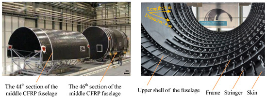
Figure 1.
Large-scale and integrated aviation CFRP structure (fuselage panels of Boeing 787 and A350-XWB) [2,3].
- (1)
- The plasticity and resilience of metal material parts are relatively good. Under the action of a common assembly force, such as a clamping force, their internal structure would have elastic deformation. With the coordination of deformation among different parts, it would not cause part damage, the assembly gaps and profile deviations among parts can be reduced by forced correction. Then, the overall deformation of the entire assembly can be restricted. However, composite materials have high brittleness, and there is almost no plastic deformation areas, making coordinated deformation difficult to achieve. When reducing the gap through forced clamping and shape correction operations, significant internal stress may be generated. For severe cases, assembly damage such as internal delamination and the crushing of the parts may also occur [4]. Therefore, while assembling composite thin-walled components, it is necessary to control physical properties such as the internal stress and damage with gap inspection and compensation.
- (2)
- Comparing to metal materials, composite materials have excellent mechanical characteristics, such as high strength, high hardness, and a high specific density. However, the mechanical properties of composite materials are anisotropic. The direction, magnitude, and layout of clamping and shape correction forces applied to thin-walled composite components need to be fully considered during assembly.
- (3)
- Composite materials are typically materials with high hardness and are difficult to machine, and they are often formed by stacking pre-impregnated materials. The above characteristics would result in unevenness and different layer parameters inside the CFRP parts [5]. As a matter of fact, the interlayer strength of each layer is usually much lower than the strength in the fiber direction. When applying assembly loads on large-sized and weak rigid composite parts, the phenomenon of the overall twisting and warping deformation of the surface and uneven gaps between the bonding surfaces can easily be generated, and they are also particularly sensitive to the presence of internal stresses during assembly.
From the above analysis, it can be seen that the forced clamping operation would have a great impact on the assembly geometry deformation and the internal stress distribution of the thin-walled CFRP component, and even cause multiple forms of damage and other quality problems in the assembled structures under serious cases.
1.2. Assembly Difficulties of Large and Integrated Composite Structures
For new CFRP thin-walled components with large dimensions and highly integrated structures, such as the weak rigid curved parts that are co-cured with the skin, stringer, and some wing ribs, frames, and reinforced walls, the design form of integrated structural features can reduce the number of assembly separation surfaces and the corresponding fixture frames. Other advantages, such as simplifying the joining process and shortening the size transfer chain, would also be gained, and behavior related to less assembly would be observed. However, the concentration of service load transmission and the mechanical response of parts would increase significantly, and the stress in the weakest matting or joining area would also be more complex. The large-scale and integrated structural characteristics would also make the assembly operation for weak rigid composite parts more dependentable on specialized fixtures, for the reason of shape retention. Combined with the uneven microstructure and the exhibited anisotropic material properties of composite parts during their formation and manufacturing process, assembly deformation is difficult to gain under positioning and clamping forces, and the dynamic evolution and distribution of local assembly stress also have strong uncertainty. Although forced correction/clamping loads can reduce some geometric errors and assembly gaps caused by composite parts with low precision, the uneven distribution of internal stress and rebound deformation would remain in different local areas of the same part [6,7]. When the local assembly gaps and stresses are too large, it is easy to cause various physical damage failures such as uneven delamination and matrix crushing, making it difficult to balance and reconcile the contradiction between shape and physical performance.
In addition, for a composite workpiece with an integrated structure and function (such as lightning protection, electromagnetic shielding, etc.), the assembly work is more difficult under stress and internal damage compared to that of common structures. Therefore, it is necessary to guide and regulate the coupled evolution process of positioning and clamping deformation/internal stress/material damage. Then, the reasonable determination of geometric gap compensation values, as well as the load limits of shape correction/clamping, can be achieved to attain dynamic “balance control” for the physical quantity. To be more specific, to improve the quality stability while assembling thin-walled CFRP components at a practical engineering site, actions such as forced positioning and clamping and forced shape correction are usually adopted. That is, additional positioning and clamping forces are applied to ensure the required spatial position and posture of key characteristics and to control assembly deformation and damage issues [8,9].
Regarding the assembly work of weak rigid composite components, it is a dynamic process characterized by a continuous evolving internal stress distribution, the interrelated generation and accumulation of damage, the progressive degradation of material properties, and local structural failure. Due to the complex nature of the internal stresses and structural damage, excessive or uneven stress distribution not only affects the geometric precision and the strength of the overall structure, but also influences the trends in stress and damage progression. In forced positioning clamping, regarding the scientific determination of the limit value of the forced clamping force, for the reasonable determination of the gap compensation value of CFRP parts, and the adaptive adjustment of the clamping force and position distribution, they are directly relevant to the control of assembly performance indicators, such as the geometric accuracy, assembly stress and deformation, and internal damage. In practical engineering, it is allowable to directly carry out subsequent joining and other process operations even when there is an amount of geometric clearance. However, considering the above assembly difficulties of large and integrated composite structures, the core process parameters mostly rely on technicians’ experience and lack quantitative modeling analysis, resulting in the serious “barbarousness” of forced assembly operation on site, as well as an extremely unstable assembly quality. Considering the above research limitations, the primary objectives of this article, i.e., the analysis of key assembly quality control technologies in the forced clamping and compensation process of composite structures, are to be explored.
This paper makes specific contributions, as follows:
- (1)
- To prevent the occurrence of uneven stress distribution and possible internal damages under the action of forced clamping, the question of what previous methods lack is answered. Then, the relevant research status on the optimization of process parameters before assembly, the flexible position–force adjustment of fixtures during assembly, and gap compensation and strengthening before assembly completion is analyzed systematically.
- (2)
- Key innovative technologies, such as force limit setting, geometric gap reduction, stress/damage evolution prediction, the reverse optimization of clamping process parameters, and precise stress/damage measurement, are proposed and analyzed in this paper. Then, it is determined that with the specific implementation solutions, geometric and mechanical assembly status coupling analysis, active control, and a collaborative guarantee could be achieved.
The outline of the subsequent content of this paper is as follows. Section 2 gives the fundamental principle of forced clamping and its typical engineering scenarios. Section 3 overviews the current research state on assembly quality control in forced clamping and compensation processes. Section 4 analyzes the key technologies for the collaborative guarantee of geometric and physical assembly performance, i.e., force limit setting, geometric gap reduction, stress/damage evolution predicting, the reverse optimization of clamping process parameters, and precise stress/damage measurement. Section 5 describes the conclusion and future research work.
2. Principle of Forced Clamping and Typical Engineering Scenarios
For composite weak rigid parts, after applying positioning constraints to completely restrict their six spatial degrees of freedom, factors such as size/form errors, fixture positioning errors, and assembly deformations can lead to inconsistent geometric states at the mating interface among parts. Then, with the occurrence of excessive assembly gaps or profile deviations, the assembly accuracy requirements would not be satisfied. Under this phenomenon, it is necessary to apply additional loads such as a clamping force, compression force, or correction force to adjust the shape of the mating surface or the parts’ assembly position [10]. To be more specific, with appropriate spatial position and posture changes or forced deformation, the local assembly clearance and overall assembly inconsistency deviation can be reduced, and satisfactory quality parameters such as the geometric shape and physical properties can be gained. In conclusion, as a passive process method to ensure assembly quality requirements, this method utilizes external loads to forcibly reduce the existing assembly gaps or deviations among parts, and it is called as “forced clamping”.
The forced positioning and clamping technique can enhance the assembly’s geometric precision and minimize the need for post-assembly finishing tasks, such as padding and surface grinding at the mating interfaces. This is achieved by modifying the interaction between large, dimensionally complex composite parts with low rigidity and the associated fixtures, through the application of controlled loads to the mating surfaces of workpieces. Although this method can partially mitigate assembly gaps, the non-uniform distribution of these gaps must be considered. The clamping force can induce uneven stress distribution and localized stress concentrations within the composite structure. However, if excessive, it can result in surface collapse, internal delamination, matrix degradation, and fiber fractures, thus affecting the mechanical integrity and service life of the assembled structure. At a practical assembly site, the unpredictable nature of materials, manufacturing processes, and operational variables makes it challenging to predict and control the internal assembly status of component structures. For the sake of reducing production costs and enhancing assembly quality and efficiency, the use of forced clamping or shaping techniques is often an inevitable practice. As illustrated in Figure 2, for the typical engineering scenario involving the assembly of composite thin-walled components, such as contoured panels and pre-assembled skeletal components with parts including ribs, spars, or frames, given the presence of manufacturing, positioning, and deformation errors, gaps at the mating surfaces between the inner contour of the panels and the outer surfaces of the skeletal structure can affect the assembly quality. To address this, shaping/clamping forces are applied at the ends of multiple CNC (Computer Numerical Control) positioners within a flexible assembly system, inducing small inward or outward deformations of the thin-walled component along its normal surface. This ensures the attainment of the desired geometric and physical assembly performance. In the depicted example, these shaping forces are applied either as tension or compression, as required.
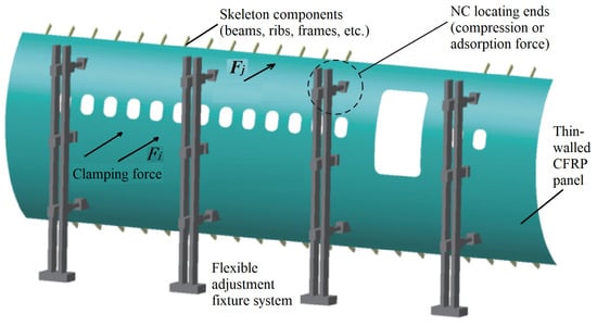
Figure 2.
Typical forced positioning and clamping scenarios in practical engineering.
3. Related Work
Due to the lower forming accuracy, significant in-plane warping deformation, and the accumulation of multi-source errors for weak rigid CFRP structures, unexpected assembly gaps/interferences and profile deviations often occur in the mating or joining areas. To address this, engineering practices commonly employ the forced clamping method by applying localized forces to passively mitigate these issues. However, considering the non-uniform distribution of mating gaps, this approach would directly impact the structural load-bearing performance. Nevertheless, from the perspectives of cost reduction and the ease of assembly operations, a certain amount of an assembly gap is also permissible. Next, the current research statuses related to assembly quality control in forced clamping and compensation are to be stated.
3.1. Process Parameter Design in Forced Assembly
In the pre-assembly stage, it is imperative to optimize the forced clamping parameters to ensure the assembly performance and for determining the necessary process inputs. Specifically, to enhance the local assembly rigidity of large-scale components, the collaborative engagement of multiple locating end-effectors across different regions is generally required for positioning tasks. For research on key positioning operations for weak, rigid, and thin-walled CFRP structures, it is inherently an optimization problem of the positioning and clamping parameters under the combined constraints of assembly geometric precision, internal stresses, and damage prevention. With the N-2-1 locating scheme, Ajani [11] developed a mathematical model of the contacting forces between the aircraft panel surface and the fixture, elucidating the influence of forces on the positioning deformation of various sub-regions of the panel, thereby minimizing the overall deformation of the thin-walled workpiece. With the permissible assembly deformation of an integrated panel with the parts as the constraint and the number and location of clamping points and the internal stresses of the laminate as objectives, Wang [12] proposed a multi-objective optimization scheme for discrete assembly positioning layouts using the method of a backpropagation neural network. The study found that the average relative error in predicting the maximum assembly deformation was only 2.93%, and the maximum prediction error for the assembly Mises stress was 7.64%, and a strong anti-deformation capability during the positioning stage of thin-walled components could be ensured. Considering physical effects such as deformation during assembly, Arista [13] utilized a hybrid position–force control approach in the FitFlex assembly project for the aft fuselage side panel (14 m × 5 m) of the Airbus A-350 XWB. Then, an optimal compliant mating system that simultaneously ensured the control of the strain/stress and geometric errors of each sub-region of the panel was constructed, and they could remain within allowable limits. To simulate the fuselage docking process, Hunt [14] developed a multi-actuator shape control system and proposed a method of finite element simulation and virtual assembly analysis with a dynamic force curve, where a process strategy that involved directly releasing the actuating mechanisms rather than applying reverse forces was adopted.
To enhance the positioning quality of composite panel structures, the common engineering practice is to apply an appropriate clamping force or shaping force, and controlled deformation can be induced. Beneficial results, such as reducing assembly deviations and improving the balance of assembly stresses and the damage distribution, can be gained. Regarding the actual assembly operations of composite structures, Lupuleac [15] suggested that assembly gaps of less than 0.2 mm do not require padding compensation and the clamping force limit for a 300 mm gap should not exceed 45 N. In terms of on-site force–position adjustments during assembly, aiming to optimize the shape deviation and loaded assembly of composite fuselage panels, Yang [16] established a predictive model concerning the displacement adjustment of locators and the displacement of shape control points, as well as the loads applied by the locators. The obtained adjustment quantities of each locator could control the internal stresses and deformation state during the assembly of composite panels, as well as achieving a balanced distribution effect. In a wing assembly shop, Mello [17] combined Taguchi methods, experimental design, and process capability analysis to establish a structural stress response model under clamping forces. Under varying clamping forces (demonstrating a linear decreasing phenomenon), the assembly deformation deviations at the interface between the intermediate ribs and the trailing edge spar could be obtained. Regarding research on setting the limits for the forced clamping of compliant composite components, taking the number, layout, and preloading of temporary fasteners as control variables, An [18] predicted the damage state of composite panels based on the stress distribution in the joining area and the 3D Hashin criteria. Then, the assembly clamping forces and the layout of temporary fasteners were optimized with the constraint of zero damage to the panels. By combining fundamental testing, multi-scale simulation, and full-factorial experimental design, Qu [8,9] conducted research on microscopic stress fields and their influence laws, microscopic damage mechanisms, and parametric characterization during forced assembly. A clamping force was applied to control the assembly quality of large commercial aircraft composite panel components. In addition, for traditional pre-assembly processes, to comprehensively address issues such as the lack of a theoretical basis, the frequent occurrence of forced assembly, and significant differences in operation efficiency, Ke [19] proposed an optimized model that can effectively avoid forced assembly and tested it on large thin-walled structural components, finding that the mismatch errors in parts’ mating surfaces caused by forced assembly were reduced.
From the above literature analysis, the following can be concluded:
- (1)
- The robustness of the positioning layout considering the actual manufacturing and clamping conditions remains an area for further investigation.
- (2)
- The challenge of efficiently evaluating the surface deformation after assembly and balancing the assembly stresses near multiple end-effectors, as well as controlling the damage state, continues to be a subject for exploration.
- (3)
- Due to the varying stress coupling methods and the obvious concentration and non-uniformity of the distribution of internal stress within the assembled structures, the current research is insufficient in addressing assembly objects with different configurations/assembly methods or different clamping load application mechanisms. A clamping force with strong position dispersion also cannot eliminate the assembly clearance effectively, and challenges such as determining the clamping force limits and the practice of applying the same clamping force at each locating end-effector also continue to hinder the realization of lean and balanced assembly objectives.
3.2. Quality Control During Assembly Operation
For the on-site assembly process, it is necessary to enhance the force–position adjustment capabilities of the assembly fixture to manage the performance of forced clamping, where geometric factors such as the inherent errors of composite parts, the physical factors of loading conditions, and environmental changes should be considered. To be more specific, by adaptively adjusting the positioning of the fixture’s end-effectors, or the magnitude of the clamping forces, the spatial position and posture of the composite thin-walled components can be changed or small assembly deformations can be induced. This strategy is implemented by controlling internal stresses and external deformations at the same time, aiming to reduce assembly coordination errors, as well as to optimize the distribution of internal stresses and potential damage throughout the forced clamping procedure.
For the adaptive adjustment of a fixture’s locating position at a practical assembly site, Bi [20] utilized a finite element model to acquire the position deviation and deformation data of the weak rigid skin panel. To be more specific, by employing partial least squares regression, an association model comprising assembly errors and the adjustments of a three-degrees-of-freedom locator was established. After intelligent solving and locator-driven deformation correction, the maximum stress was reduced from 13.59 MPa to 4.34 MPa following three adjustments. Concurrently, the shape deviations in the X, Y, and Z directions were decreased from 0.144 mm, 0.152 mm, and 0.042 mm to 0.015 mm, 0.016 mm, and 0.009 mm, respectively. With the adoption of a discretized approach under the constraints of motion freedom and geometric tolerance, Sun [21] developed a quantitative evaluation and multi-objective optimization model for the assembly gaps of composite panels. By adjusting the flexible locators, the distribution of assembly gaps was optimized and minimized, and a comprehensive optimization rate of 31.12% was achieved in numerical simulations, closely matching the measured value of 25.5%. Focusing on the shape deviation and assembly load of composite fuselage panels as optimization objectives, with the influence coefficient method, Wang [22] established predictive models including locator displacement adjustments and the displacement of shape control points, as well as the applied loads of the locator. A solver model based on the NSGA-II algorithm was proposed for the motion of locators to control the stress and deformation during panel assembly. Experimental results confirmed that the assembly precision was within ±0.6 mm~0.8 mm, and a comparison of the position deviations before and after optimization is shown in Figure 3, where CP stands for the control points of the panel shape. In addition, to simulate the docking assembly process of composite fuselage components, Hunt [23] introduced a finite element simulation method considering a dynamic force curve and virtual assembly analysis based on a developed multi-actuator shape control system. An optimized process strategy of directly releasing the actuating mechanism rather than applying a reverse force was implemented in the assembly field.
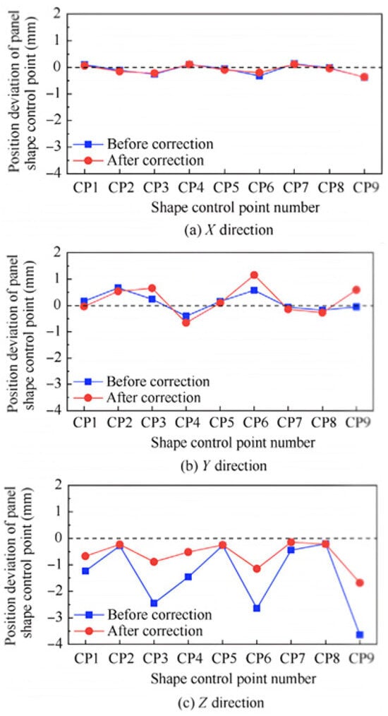
Figure 3.
Position deviation of the panel shape control points in the X, Y, and Z directions before and after correction [22].
For the adaptive adjustment of the fixture’s clamping force, with the interactive scanning of each mating part before assembly, Rezaei [24] adopted digital twin technology to adjust the clamping devices in real time. This approach could reduce geometric assembly deviations by 57%. Utilizing actual workshop resources provided by an aircraft manufacturer, Mello [17] adopted Taguchi methods, experimental design, and process capability analysis to establish a functional model of clamping force application, where the assembly behavior could be predicted to achieve better geometric quality. Specifically, in the case of wing assembly, the clamping force limit applied to the product was defined as 900 N. Addressing the assembly deformation of flexible parts in aircraft structures, and with an analysis on the relationship between the load condition and displacement of different assembly steps, Tan [25] developed a model for assembly dimension variation considering clamping force changes based on the influence coefficient method. This model could reduce assembly errors at key characteristic points without correcting the clamping force at over-constrained locating points. For robotic-assisted assembly positioning, Yang [16] constructed a Gaussian process surrogate model of composite frame part assembly and stated that the assembly force should be controlled within the range of 10 N to 40 N, with the aim of preventing insufficient and excessive force control impacts on the structural strength. The optimal assembly force of 11.50 N was determined through process experiments. In addition, by deploying fiber Bragg gratings on the beams and frames of the reconfigurable fixture, Hu [26] developed a real-time monitoring system for the fixture’s strain data. Then, a mapping model from the strain to the clamping force was established, where the fixture’s structural deformation and the clamping force values could be determined, and timely and accurate physical state sensing information for the assembly process could also be provided.
For the force and position adjustment of assembly fixtures, considering physical effects such as assembly deformation, Bertelsmeier [27] utilized a collaborative assembly force control system with multiple industrial robots. By measuring the deformation of composite thin-walled workpieces and applying numerical optimization methods, precise force control compensation with robots was adopted to control the deformation of composite panels. With the construction of a deformation behavior model for composite panel assembly, Schmitt [28] proposed an integrated assembly system with a six-degrees-of-freedom locator and a measuring device. To be more specific, with an optical 3D scanning system to measure the deformation of a skin panel and sensors to measure the bearing force of the locator, a load deformation prediction model for the panel was established, where the required compensation force of the vacuum suction cups was determined, and the movement of the locator was controlled to compensate for the manufacturing deviations and deformation caused by gravity. However, this approach requires a large number of load deformation tests, and it is challenging to ensure the profile accuracy of large-scale workpieces. In the case of the Airbus A-380 wing panel [29], after the panel was positioned on the skeleton component using a fixture with different locating ends, two hydraulic arms were adopted for precise position control, while the other hydraulic arms were applied cooperatively with assembly forces to induce the panel’s deformation. The collaborative force–position control method could enable the panel to fit against the skeleton component tightly, and the fitting gaps could be reduced effectively. Additionally, although the assembly force between the panel and the fixture can be monitored during the forced clamping process, the internal stresses of the assembly structure cannot be obtained directly, and the setting of the force limits still lacks a scientific basis. Based on the precise positioning of a composite panel according to the theoretical design shape, Ramirez [30] achieved the spatial position and posture adjustment and shape correction of the panel through the movement of different locating devices. Similarly, the force/torque sensors between the suction cups and the actuators could monitor the force on the panel, and the material damage could be controlled to some extent; however, the internal stress state of the assembled structure could not be acquired directly.
From the above literature analysis, the following can be concluded:
- (1)
- The efficient evaluation of assembly deformation for the entire CFRP panel component, the evaluation of the stress near the locating ends, and the acquisition and control of the damage state after barrel segment docking still require further investigation.
- (2)
- With the optimized clamping process parameters and implementing force and position collaborative control in the assembly field, if the mating gaps among composite thin-walled parts cannot be effectively reduced and the assembly shape cannot be effectively guaranteed, engineering repair practices often resort to adding shims or grinding the assembly surfaces. These methods aim to achieve a tight and uniform fit between mating surfaces before the completion of assembly, and this phenomenon is known as passively ensuring assembly quality. Under the context of digital manufacturing, compensation and repair work primarily involves two major steps, i.e., gap measurement and shim compensation. Gap measurement provides the data basis for the production of shims, while gap compensation uses suitable shims to increase the mating area of different parts. The precision and implementation strategy of these two steps directly affect the mating quality of the assembly surface, as well as the geometric and mechanical performance of the joined structure.
3.3. Gap Compensation Before Assembly Completion
For the measurement of mating gaps in large composite structures, by segmenting the gap area and utilizing projection operations, Long [31] extracted gap feature points based on the differences in the local point cloud density. Experimental results showed that the average measurement error of the skin gap and step difference was 0.005 mm, but data acquisition and processing were susceptible to interference from the equipment accuracy and environmental noise. To address the measuring difficulties and light occlusion, Wang [32] proposed a combined method by constructing a measurement scheme integrating laser trackers, 3D scanners, and photogrammetry. Although high-precision data on the assembly position and posture, mating gaps, and surface quality could be obtained, there were drawbacks such as high computational complexity and low data fusion efficiency [33]. In response to these shortcomings, by using machine learning to analyze the historical data of assembly production and combining the optimization of sparse sensor measurements with data feature extraction, Manohar [34] proposed an intelligent prediction method for geometric assembly gaps. Using only 3% of the key laser scan data, it could successfully predict 99% of the shim gaps within the tolerance range and reduce the number of measurements, and reliable guidance for the on-site operation of gap compensation could also be gained. Based on the error state of the interface between the parts of the composite panel and the metal frame, Muelaner [35,36,37,38,39] proposed predictive shimming technology. To be more specific, after accurately fitting the gaps and interference that required repair and shimming, the compensation operations could be carried out according to the visual cloud map contained in the compensation plan.
After accurately obtaining the measurement data of the gaps between composite parts or between composite and metal parts, it is necessary to select or fabricate appropriate shims to compensate for the gaps and analyze the mechanical compensation effect after shimming. At the theoretical level, Hühne [40] proposed a 3D progressive damage model with continuous degradation laws, where the impact of the liquid shim thickness on the loading performance of single-lap composite bolted joints was revealed. Considering the Puck criterion and the material’s index degradation process, Gerendt [41] studied the mechanical behavior of double-lap composite bolted joints. In practical applications, regarding the local assembly gaps of composite wing box panels, through an analysis of measurement data, Chang [42] found that the maximum assembly strain occurred at the location of the maximum gap and for uneven mating gaps, mixed shims could control the deformation at the root or edge of the gap better; the maximum strain could also be reduced by about 20%. For the full-field strain on the surface of large-sized and weak rigid CFRP components, An [43] compared the strain field measured using 3D-DIC with the simulation using ABAQUS finite element analysis. It was found that both liquid and glass fiber shims could improve the stress and damage state around the hole to varying degrees depending on the shim’s material, and the thicker the shim, the bigger the strain around the hole in the composite laminate. Considering that the assembly gaps in the mating area often have irregular shapes and can span multiple fasteners, An [43] also established a simplified span model for assembly gaps and used experimental and finite element methods to study the impact of forced clamping operations on the assembly stress and strain. It was found that liquid shims could increase the strain in locally mating and less compressed areas, but the strain state in dangerous areas at the edge of the workpiece could be improved, resulting in a more balanced overall strain distribution in the assembled structure (Figure 4). Where Figure 4a,b represent the effective contact area difference of the joint interface, the left portion shows the experiment result, and the right portion shows for the results gained with finite simulation. Figure 4c represents the effective contact area difference of the joint interface under the condition of shimmed/non-shimmed assembly. It was also found that when the assembly gap was in the range of 0.2 mm to 0.7 mm, hydraulic shims had a better filling effect. By scanning the composite wing surface, Wang [44] reconstructed a 3D model of the mating area to ascertain the actual distribution state of local assembly gaps and designed optional shim schemes under different constraints. Then, the best scheme could be selected using finite element analysis. This research showed that liquid shims have high initial stiffness but a lower load capacity than solid shims, and mixed shims have the same load-bearing capacity as solid shims but with higher initial stiffness.
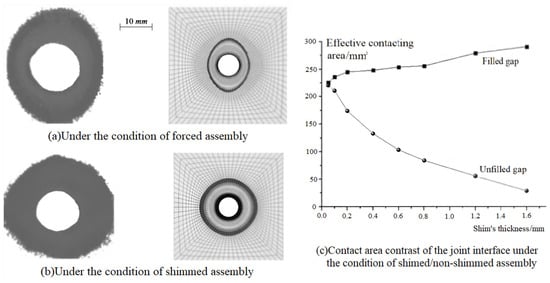
Figure 4.
Comparison of effective contacting areas of joining surfaces [43].
From the above literature analysis, the following can be concluded:
- (1)
- Although the control of assembly gaps and a reduction in assembly stresses can be achieved, further research is still needed, i.e., on the change in the assembly stress state introduced by fixture clamping and the influence of the shims on the mechanical performance of the assembled structure.
- (2)
- Gap compensation can make the internal assembly stress and strain distribution more balanced, and different shims have varying effects on improving the tensile stiffness and load-bearing capacity of the joining structure, which can effectively compensate for the impact of forced positioning and clamping operations on weak rigid composite thin-walled components. However, it is necessary to fully consider the randomness and non-uniformity of the shapes and contours of the assembly gaps, as well as the improvement of the shim fabrication process under non-uniform gaps.
3.4. Research Status Summary
The analysis from Section 3.1, Section 3.2 and Section 3.3 reveals that the current literature primarily addresses three integral stages to effectively utilize forced positioning and clamping techniques, ensuring the satisfactory assembly geometry and physical status of CFRP thin-walled components. To be more specific, these include the following: (1) The optimization of forced clamping process parameters: by combining theoretical analysis, simulations, and experimental studies and considering the workpiece’s manufacturing error and on-site assembly conditions, the aim is to derive an optimized positioning and clamping strategy and set of parameters before assembly, and a solid foundation for ensuring the on-site assembly quality through meticulous process analysis could be established. (2) Force–position adjustment for fixture positioning: the adjustment of the fixture’s locating effectors and the clamping load is finely configured, and the assembly’s geometric position and posture and physical state distribution can be adjusted within the design specifications. (3) Shim compensation for geometric matting gaps: for gaps that cannot be eliminated after the above two measures are taken, it is necessary to take measurement and compensation actions for carrying out regional and quantitative repair operations to avoid a negative impact on the assembly’s mechanical performance.
4. Key Technologies for Collaborative Guarantee of Geometry and Physical Assembly Performance in Forced Assembly
When applying forced clamping or shaping operations to CFRP thin-walled structures on assembly fixtures, the magnitude of the clamping force directly affects the overall geometry and physical performance of the assembly. To achieve active control of the coupling process and to ensure the collaborative protection of the assembly’s geometric and physical performance, it is necessary to first set the limit range for the clamping force, considering both macro and micro levels. In addition, based on the research on the formation and expansion theory of the assembly geometry and physical performance, for large geometric mating gaps between parts, i.e., more than 0.2 mm, the direct application of forced clamping loads should not be adopted to eliminate them. Under this situation, it is essential not only to design a reasonable clamping scheme for weak rigid workpieces and precisely control the flexible adjustment process, but also to predict the potential damage patterns based on the internal stress distribution and to consider the balance and coordination of geometric and physical states during forced clamping. Then, the optimal process parameters during forced clamping could be inversely optimized to ensure an improvement in the assembly quality. Furthermore, during the entire forced assembly process, the precise measurement and analysis of internal stresses and the damage status would also be required. Then, accurate on-site data support for the formulation and implementation of process optimization strategies could be achieved, as well as the beneficial effects of digital–physical integration and consistency. The following sections will analyze the connotations and specific implementation details for the relevant key technologies.
4.1. Force Limit Setting
During the forced clamping process, if the applied force exceeds the allowable range, it may directly lead to the damage or destruction of the CFRP thin-walled parts. Due to the significant difficulties in studying the mechanisms determining the assembly quality in anisotropic composite materials, there is a lack of scientific modeling and design schemes. To ensure the appropriate conduction of the assembly process and the guarantee of assembly quality, it is necessary to deeply investigate the relationship between (1) the mechanical properties of composite materials, (2) forced assembly process parameters, and the structural geometry and mechanical performance response. This will help to achieve the precise control of the forced clamping force, preventing phenomena such as geometric shape deviation, excessive internal stress, and structural damage. The resolution of the above key issues can be achieved with the technical solution described in Figure 5.
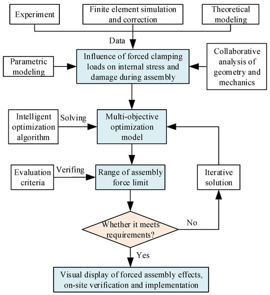
Figure 5.
Method for setting the limit value of the forced assembly load.
The specific implementation steps and process are as follows:
- (1)
- Through the combination of experimental and finite element methods, compare and modify the finite element simulation model and parameters and obtain the influence of the assembly forces on the internal assembly stress and damage of thin-walled CFRP structures. To be more specific, (1) monitor the key indicators such as the clamping force, stress, and damage state during the assembly process. Through the installation of force sensors at the flexible clamping units on the surface of the workpiece, the changes in assembly force data could be collected and monitored in real time. (2) Dynamically monitor and accurately evaluate the stress and damage state during the forced assembly process, with acoustic emission, DIC (Digital Image Correlation), and ultrasonic measurement techniques. (3) Investigate the influence of different assembly force magnitudes on the internal stress distribution and potential damage degree with experimental analysis. Then, after establishing a finite element model considering the actual assembly process, the accuracy of the simulation could be validated and corrected with experimental data. Finally, the influence relationship could be determined with the simulation model and data.
- (2)
- Express the above influence principle with parametric modeling, perform the multi-objective optimization of forced assembly parameters considering the coordination of assembly geometry and physical performance indicators, and obtain the mathematical model for setting assembly force limits. To be more specific, (1) to determine the influence relationship between the forced assembly force and the corresponding stress and damage that are obtained from experimentally validated and finite element simulations, carry out parameterization processing. Then, under the given assembly process scheme, the table reflecting the input and output relationships for the forced assembly force and assembly quality effects could be obtained quickly. (2) Define the optimization model, where the position coordinates and magnitude of the assembly force are defined as optimization design variables. The reasonable constraint conditions are set as the following: the assembly force must be applied within an effective spatial range that cannot cause damage to the material. The optimization goal is set as the following: by optimizing the magnitude of the assembly force, minimize the internal stress and structural damage while ensuring the minimum assembly gap thickness. Finally, the mathematical optimization model for the relationship between the assembly force, gap thickness, and damage to the material can be established.
- (3)
- Solve the mathematical model of assembly force limits with intelligent optimization algorithms and obtain the setting interval for the forced assembly force limits using the assembly geometry and physical performance collaboratively. To be more specific, (1) perform an optimization search with multi-objective intelligent optimization algorithms, i.e., initialize a population containing several assembly force limit schemes and evaluate their merits with a fitness function. (2) Select excellent schemes as “parents” and generate new assembly force limit schemes through crossover and mutation operations. Introduce randomness to maintain the population’s diversity and avoid local optimization convergence. (3) Continue iterating until a design with significantly better assembly force limit schemes is found or the preset maximum number of iterations is reached; then, the comprehensive goal of determining the minimum assembly gap thickness and the minimum damage degree could be achieved.
- (4)
- Evaluate the effectiveness of the assembly force limit settings using a combination of measurement experiments and the parametric modeling of simulation results and visually display the results of the forced assembly geometry and physical performance. To be more specific, (1) within the determined range and spatial locations of the assembly force limits, apply a series of locating point values to the experimental validation of the assembly force limits in the defined segments. (2) Use finite element simulation to calculate the assembly geometry and physical performance state, visually displaying assembly effects such as the gap elimination rate, stress/strain distribution, and detected damage. (3) Verify the reliability of the model and the rationality of the modeled assembly force limits by comparing the finite element simulation data with actual measurement data.
4.2. Geometric Mating Gap Reduction
For CFRP assembly structures, the geometric gap thickness between parts with curvature directly affects the overall mechanical strength, stability, and sealing performance. Essentially, during forced positioning and clamping operations in thin-walled composite structures, a reduction in the mating surface gaps is achieved by altering the geometric shape with a clamping force to eliminate it. During the operation of applying forced loads, as the mating gaps decrease, the internal assembly stresses between the mating surfaces increase, and there is a risk of material damage. From the description of this engineering phenomenon, it can be observed that the reduction in assembly geometric gaps and the increase in assembly stresses are a contradictory pair that is difficult to balance. Therefore, the key to implementing geometric gap reduction technology is to eliminate the mating gaps while avoiding excessive internal assembly stresses. The resolution of the aforementioned issue can be achieved through the scheme described in Figure 6.
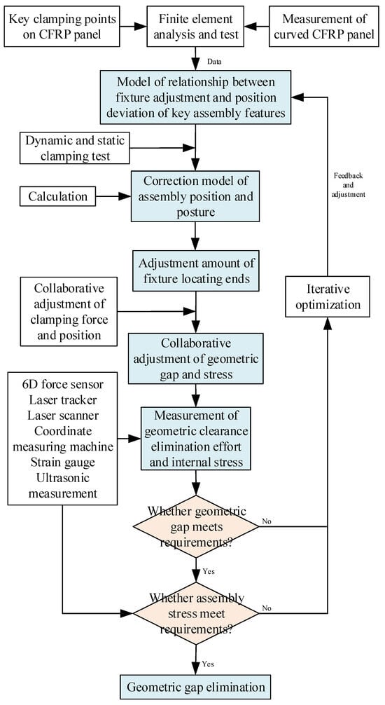
Figure 6.
Method for eliminating geometric gaps during forced clamping process.
The specific implementation steps and process are as follows:
- (1)
- Key positioning features on complex CFRP curved surfaces are selected and high-stability clamping points are determined with 3D scanning and mechanical simulation modeling. To be more specific, (1) based on the integrity characteristics of thin-walled composite parts, 3D scanning is adopted to measure and digitize the mating surfaces with curvature, and key points representing the complex curved features are identified. (2) Considering the actual assembly loads and working conditions, points located in the support structure or areas with high strength and stiffness are prioritized as clamping points. (3) Mechanical simulation is then adopted to optimize the clamping scheme to adapt to the physical properties and engineering requirements, which lays the foundation for reducing assembly geometric gaps in forced positioning and clamping.
- (2)
- Considering the above high-stability clamping points, establish a model of the associations between the flexible adjustment amount and the key assembly position and posture deviations. Specifically, using the relative positional relationship between the selected clamping points and the center coordinate system of the locator, adopt deterministic positioning algorithms. Then, convert the position error of the clamping points into a mathematical model of the adjustment amount of the fixture locator and the theoretical assembly position and posture of the weak rigid workpiece. After forming the adjustment strategy, the key assembly features can reach the ideal position under the position adjustment of the clamping force.
- (3)
- Obtain high-precision parameter values of the associative model with multi-factor dynamic and static simulation tests and modify the associative model to obtain a positioning and clamping deviation correction model. To be more specific, (1) according to dynamic and static clamping simulation tests with multiple factors and the parameters of the material properties, changes in thickness, and coefficients of thermal expansion, improve the associative model and determine high-precision parameter correction values for positioning adjustment. (2) Establish the correction model for the geometric assembly position and posture that accurately reflects the actual clamping conditions. Meanwhile, also consider the material properties and environmental factors to improve the practicality and adaptability of the clamping strategy. Then, the precise control of the component’s assembly error can be gained during forced clamping.
- (4)
- Solve the assembly deviation correction model with iterative algorithms and experimental measurements and reduce the geometric gap between the mating surfaces. To be more specific, (1) based on the requirements for assembly geometric gaps, adopt numerical iterative algorithms to solve the correction model. (2) For each clamping calibration point, adjust the locator iteratively according to actual position deviations and ideal target positions. Then, optimize the clamping adjustment amount continuously until all clamping points reach the preset precision. Finally, a reduction in the geometric gap between the mating surfaces can be achieved.
- (5)
- Adjust the assembly stress and geometry clearance based on force sensing data and finite element stress analysis, as well as the collaborative flexible adjustment of clamping force load and locating position constraints. To be more specific, (1) install six-axis force sensors around the clamping points to monitor the clamping force in real time and predict the internal stress distribution under different clamping forces with finite element analysis. (2) Establish the mechanical model of the assembly force and internal stress through the collaborative flexible adjustment of clamping force and locating position constraints. Then, by guiding the adjustment of the clamping force, the internal stress will remain within safe limits while eliminating the mating gap, i.e., preventing damage to the material and ensuring a reduction in the assembly geometric gaps. Going into more detail, in the finite element software, by combining the actual assembly conditions, the material properties, layering, and mechanical performance parameters are assigned and the process constraints are defined. Then, a simulation model based on cohesive zone elements is established to accurately represent the internal stresses. Additionally, a secondary step is conducted in ABAQUS software to incorporate the classic damage criteria for composite laminates, i.e., the improved Hashin’s 3D failure criterion, and the failure safety margins for seven micro-damage forms are precisely characterized by the damage index.
- (6)
- The assembly position and posture, mating gap, key assembly deviations, and internal stress among the parts are measured, and it is judged whether the geometric accuracy and physical stress indicators could meet the presets. Specifically, after the assembly work is completed, high-precision measurement tools and technologies, such as ultrasonic, are adopted to conduct an all-around, high-precision measurement and inspection of the assembly effect, where the actual position and posture of key parts, the gap and deformation of the mating surfaces, and the internal stress distribution are considered. Through precise clamping adjustment, the elimination of the geometric gap between the mating surfaces and the internal stress could meet the requirements without causing material damage or failure, and the assembled structure could also meet the design requirements for mechanical performance and assembly functionality.
4.3. Internal Stress/Damage Evolution Prediction
For large-scale and weak rigid CFRP components, to predict and control the formation and evolution of stress and damage in composite parts under forced clamping operations, as well as the changes that occur during the assembly process, a comprehensive research approach integrating finite element simulation, fundamental joining experiments, and the theoretical analysis of composite damage can be adopted. This approach fully takes into account the impact of macro and micro parameters, such as the geometric shape and size of the assembly structure, material properties, layup patterns, and the coupling of multiple physical fields during assembly, on the outcomes of stress and damage propagation. The resolution of these issues can be achieved with the scheme described in Figure 7.
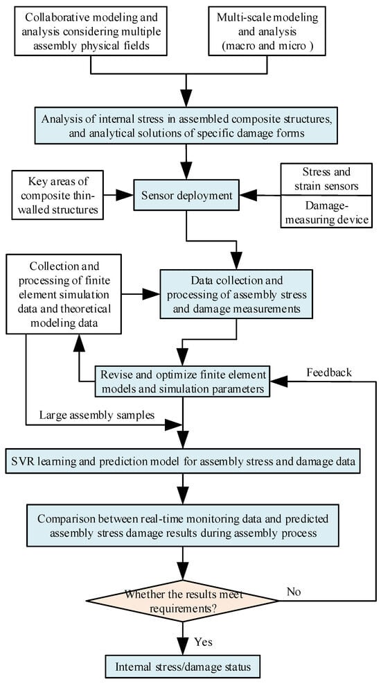
Figure 7.
Prediction method for internal stress and damage evolution during forced clamping process.
The specific implementation steps and process are as follows:
- (1)
- Combine multi-physical field collaborative modeling and macro- and micro-scale modeling, obtain the mechanical analysis data for the assembly stress distribution and specific damage patterns, with the consideration of the heterogeneous distribution characteristics of composite laminate components. To be more specific, (1) establish a multi-scale stress bridge matrix based on continuum mechanics theory. When damage occurs within a single cell, calculate its reduced material stiffness and then obtain the reduced equivalent stiffness of the corresponding micro-unit using the macro–micro stiffness equivalence matrix. (2) Taking into account factors such as the layup patterns, structural geometry, clamping constraints, applied boundary conditions, forced clamping loads, and assembly deformation, establish a macro–micro stress quantification calculation model for forced assembly. This model could provide the internal stress field and deformation state of the fiber, matrix, and interface. (3) After integrating the internal stress factors of clamping, establish a 3D progressive damage initiation model under forced loading. Through the formulation of damage initiation criteria and the obtained analytical solutions for specific damage patterns and their distribution, more explanatory insights for the improvement of the clamping process could be provided.
- (2)
- The data acquisition device is positioned in key assembly areas and the measured data for stress and damage are collected during the forced clamping process. Specifically, dense arrays of precision strain sensors are installed in the key assembly areas. Then, non-destructive methods such as acoustic emission, DIC (Digital Image Correlation), and ultrasonic measurement techniques are combined to collect stress, strain, and damage data in real time and comprehensively. Finally, a high-density monitoring network can be built.
- (3)
- Extract the data features after processing and analyzing the collected experimental stress and damage data. To be more specific, (1) clean the data to remove missing and abnormal values. (2) Filter the data noise, and extract stress and damage data features with signal processing techniques. In addition, enhance the data quality with low-pass, median, and Kalman filtering techniques, as well as adopting wavelet analysis and Fourier transforms to deeply delve into the damage signals. (3) Adopt data standardization and normalization processing actions, and provide a clear and reliable data foundation for the subsequent data processing efficiency of machine learning solutions.
- (4)
- Establish a finite element simulation model for assembly stress and damage considering mechanistic and actual measured data, and modify or optimize the model and parameters based on comparative deviation analysis. To be more specific, (1) considering the material properties of composites and the characteristics of thin-walled structures, as well as actual constraints such as the forced clamping conditions, integrate finite element simulation data with actual measured data and calculated data from mechanistic models, and establish a corrected finite element simulation model for the positioning stress and damage. (2) Adjust the simulation model parameters until the predicted results closely match the experimental results. (3) Analyze the stress responses, damage evolution, and dimensional changes under different clamping parameters and obtain the impact on the assembly quality; then, the issue of a large sample of data for data-driven approaches can be accurately addressed.
- (5)
- The large sample of data on the assembly quality are trained with the SVR (Support Vector Regression) method, and the stress distribution and the damage occurrence are assessed under different clamping conditions. Specifically, based on a large sample of high-quality data from finite element simulations, using the SVR data processing method and radial basis kernel function, the data items are mapped to a high-dimensional space to address non-linear problems [45]. Then, the parameters are optimized to minimize prediction deviations, and the model is trained based on the prediction data for the assembly internal stress and damage distribution. Finally, through consistency adjustments using digital virtual simulation and on-site measured data, the stress distribution and the possibility for damage under different clamping conditions can be quickly and accurately assessed in advance.
- (6)
- Monitor the assembly process of weak rigid composite thin-walled components in real time and input the data into the assembly stress and damage prediction model. If the predicted stress distribution and damage area results exceed the danger thresholds, alarms will be triggered. Specifically, real-time monitoring data from the assembly process are input into the stress and damage prediction model. If any risk of damage exceeding the safety thresholds is predicted, the system issues an alert immediately. This facilitates the rapid and iterative feedback analysis of the forced clamping process and could also effectively prevent excessive internal assembly stresses and structural failures. Finally, the safe production and the service life of the assembled structures could be ensured.
4.4. Reverse Optimization of Clamping Parameters
While optimizing and adjusting the forced positioning and clamping process parameters, such as the magnitude, position, and sequence of clamping forces, the complex interactive relationships and bidirectional constraints among different types of parameters lead to a high degree of uncertainty. By clarifying the intrinsic correlation rules between forced assembly parameters and the geometric–physical indicators (i.e., the forward problem), data empowerment-driven methods can be employed to reduce the multi-source uncertainties, as well as forming inverse iteration control for the process parameters. While controlling the assembly performance indicators, essentially, to solve the deviation-optimizing problem of the actual and ideal performance, it is a typical inverse problem model. With the aid of inverse technology, and based on the characteristics of composite material parts under ideal assembly conditions, tools such as artificial intelligence, mathematical models, and finite element methods could be adopted to obtain the parameter set for forced positioning. This solution could effectively regulate the stress distribution and prevent the internal material damage or deformation generated by concentrated assembly stress and directly guide the completion of high-performance assembly operations. The resolution of these issues can be achieved through the scheme described in Figure 8.
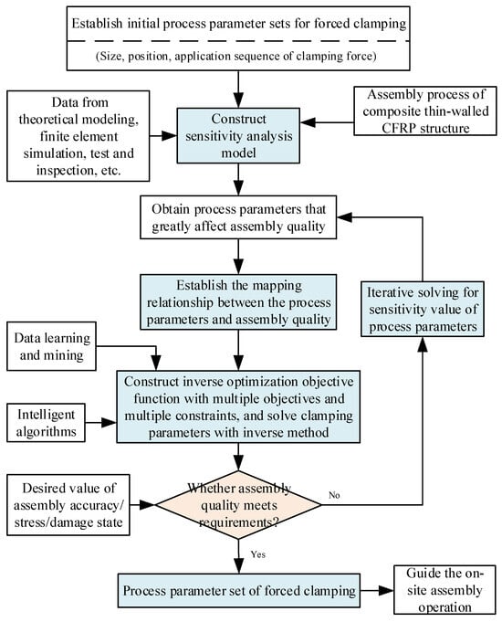
Figure 8.
Optimization of process parameters for forced clamping with reverse calculation.
The specific implementation steps and process are as follows:
- (1)
- Calculate the sensitivity values of the forced clamping parameters affecting the assembly quality, and identify the key clamping process parameters. Specifically, using theoretical modeling calculations, finite element simulation analysis, and actual test data, identify the process parameters that significantly impact the assembly quality, such as the magnitude, position, and sequence of clamping forces, and adopt sensitivity analysis methods to measure the influence of these parameters. Then, construct key parameter sets and arrange them in descending order. This solution could quantify the forced clamping parameters that have a significant impact on the assembly quality.
- (2)
- A mathematical model is established for the forward mapping relationship between the assembly process parameters and the assembly quality. Specifically, using the permissible range of key clamping process parameters as constraints, and considering the expected value of the assembly quality, the optimization goal is to minimize the deviations of mating gaps and assembly stress and damage. Ensuring that no damage occurs and each key process parameter remains within its engineering-allowable range, the complex coupling relationship between the parameters and the ideal assembly quality indicators is analyzed. Finally, a forward mapping relationship mathematical model of the assembly process parameters and assembly quality could be constructed.
- (3)
- Construct a multi-objective and multi-constraint reverse optimization objective function, and determine the optimal process parameters for forced clamping through stepwise iterative and reverse derivation. To be more specific, (1) use intelligent optimization algorithms and data learning and mining techniques, develop a reverse solution strategy for the forward mapping relationship mathematical model. (2) While satisfying the constraints of the clamping force magnitude, position, and sequence, the iterative solution of the mathematical optimization model under multi-objective and multi-constraint conditions is completed through stepwise iteration. In addition, using the fitness function evaluation in the optimization algorithm, the process parameter sets that can maximize the assembly quality are determined through reverse derivation, and the globally optimal parameter configuration that maximizes the assembly quality can be gained.
- (4)
- Verify the optimal forced clamping parameters and feed back the optimization results with an inverse solution. Specifically, based on the optimized process parameters, design test plans, and the appropriate adjustment control parameters of the fixture, execute actual forced clamping operations and performance tests with high-precision instruments to monitor the stress, strain, and damage of the composite thin-walled structure under the optimal process parameter configuration. After comparing the assembly results with the preset expected values, if they are within an acceptable error range, the subsequent operations can be carried out according to the current set of forced clamping process parameters, and if there is a significant deviation, the identification and optimization phase for the clamping process parameters should be optimized, and a new round of iterations should be undertaken until the expected assembly quality and stress requirements are met. This closed-loop process could ensure the high assembly performance of composite thin-walled aerospace components.
4.5. Precise Stress/Damage Measurement
In the assembly process, under the influence of clamping loads, clamping position deviations, and joining forces, stress concentration phenomena would occur within the assembled structure. Excessive internal assembly stresses may lead to damage and failure within the composite parts, such as matrix crushing, interlaminar delamination, and fiber breakage. Most of these damage phenomena are invisible to the naked eye. In addition, the key objective of optimizing the forced positioning and clamping process is to control the internal stresses to suppress damage, as well as assessing and optimizing the rationality and effectiveness of the designed assembly process based on inspection results. As a result, it is essential to accurately measure the assembly stresses and damage in a timely manner. In the field of composite structure monitoring, due to the various combinations of fibers and matrices and the orientation of the layers, the diverse macro- and micro-damage states, such as the stress distribution, interlaminar delamination, fiber breakage, and delamination, are often difficult to effectively identify with a single detection method. Particularly in complex assembly environments, localized damage distribution and patterns caused by an uneven stress distribution are more concealed, which limits the accurate assessment of the structural assembly performance, and this is one of the urgent challenges needing to be addressed in practical engineering. The resolution of this issue could be achieved with the integration of acoustic emission, DIC, and ultrasonic measurement techniques [46,47]. They would complement each other in a collaborative effort to provide comprehensive data support for assessing complex stress and damage patterns, guiding on-site assembly operations quickly and effectively. The solution to the problems can be realized through the scheme described in Figure 9.
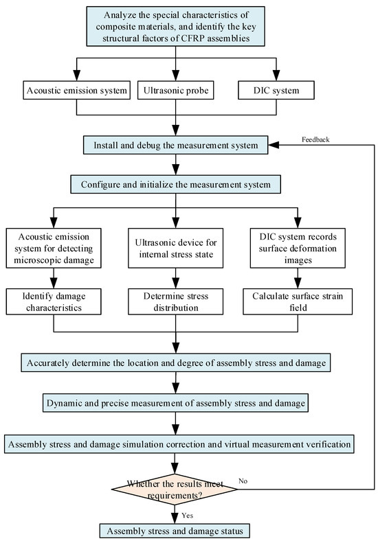
Figure 9.
Precise measurement for internal assembly stress and damage of CFRP structure.
The specific implementation steps and process are as follows:
- (1)
- Establish the measurement plan for the micro-damage, internal stresses, and surface deformation. To be more specific, (1) analyze the inherent characteristics of the composite materials, such as the composition and layering sequence, and their influence on acoustic wave propagation. (2) Conduct a finite element mechanical simulation analysis of the assembly process to identify key structural elements, stress transfer paths, and potential damage areas in composite thin-walled structures. (3) Propose an integrated plan for acoustic emission (AE) sensors to measure micro-damage, ultrasonic probes to measure assembly internal stresses, and the arrangement of DIC marker points, while ensuring the precise calibration of each detection system. Then, a non-destructive measurement scheme for assembly stress/damage and surface deformation/strain data will be gained.
- (2)
- Deploy AE sensors, ultrasonic probes, and DIC markers in critical areas of stress transfer and potential damage. Specifically, based on the measurement scheme, install the above sensors and optimize the layout of ultrasonic probes in these critical areas, to ensure both the static monitoring of the internal structural integrity and the dynamic capture of stress changes during assembly. Simultaneously, apply markers for the DIC system to provide high-contrast observation data. Then, a complete assembly quality measurement device will be established.
- (3)
- Monitor the micro-damage signals, internal stress states, and surface deformation data in real time and synchronously. Specifically, initialize the integrated measurement system by setting monitoring parameters, configuring high-precision probes, installing the DIC system, and ensuring the time synchronization and preliminary data fusion processing of all monitoring equipment. This enables the measurement device to capture AE data for micro-damage, ultrasonic data for internal stresses, and DIC data for surface deformation simultaneously and in real time. Then, the foundation for the real-time monitoring and data analysis of the assembly quality will be laid.
- (4)
- Analyze the AE data to identify the micro-damage characteristics, analyze the internal stress distribution with the ultrasonic data, and calculate the surface strain field based on the DIC data, and construct a stress/damage correlation model. To be more specific, (1) perform noise reduction processing and machine learning analysis on the collected acoustic emission signals, then identify and classify the type and severity of the assembly damage and generate the accurate location and three-dimensional morphology of the damage. (2) Utilize ultrasonic image analysis and Digital Image Correlation techniques to reveal the location and size of internal defects, and track the displacement changes over time at each ultrasonic marker point to construct a surface displacement field of the workpiece. (3) Integrate and convert the micro-damage data, internal stress data, and surface deformation data with interpolation and gradient calculation methods, then depict the surface strain field and internal stress field of the composite component accurately. (4) Based on physical principles and experimental data, adopt data-driven methods to analyze the quantitative relationship and correlation model of assembly stress and damage.
- (5)
- Judge the position and distribution of stress and damage. Specifically, (1) integrate measurement information on the micro-damage characteristics, internal stress distribution, and the surface strain field, and unify data processing and time synchronization. (2) Use multi-dimensional data fusion techniques, such as Bayesian networks, to precisely locate the areas of excessive assembly stress and damage. (3) Assess the deviation severity and development trends, such as the length of internal cracks and the area of delamination, and analyze the influence of the stress concentration on the initiation, propagation, and evolution of assembly damage in composites.
- (6)
- Calibrate finite element simulation models and parameters, and predict the assembly risks with virtual measurement validation. Specifically, (1) using the measured internal stress and damage data, calibrate finite element simulation models and parameters, and obtain an accurate finite element simulation model for digital–physical integration and consistency. (2) Perform virtual measurement analysis with the corrected finite element model to reduce the amount of on-site assembly testing and measurement. (3) Conduct virtual measurement prediction validation under other assembly conditions to quickly and accurately predict the balance of the assembly stress distribution and the occurrence of damage phenomena. (4) Assess and optimize the rationality and effectiveness of the assembly process, and guide on-site assembly operations effectively.
5. Conclusions and Future Research
5.1. Conclusions
For large and integrated composite structures, to accurately predict and control the assembly deformation, stress, and damage states during the forced clamping process, and based on the in-depth study of the collaborative control mechanism for the assembly shape and performance, as well as macro–micro coupling analysis, three optimization strategies were analyzed, i.e., clamping parameter optimization before assembly, the fixture’s adjustment during assembly, and gap compensation before assembly completion. Then, five key technologies were proposed, i.e., force limit setting, geometric gap reduction, stress/damage evolution prediction, the reverse optimization of clamping process parameters, and precise stress/damage measurement, as well as the specific implementation methods. Focusing on the assembly geometry and physical performance, the entire solution enables the coupled analysis, active control, and balanced assurance of the geometric shape and physical performance indicators during the forced clamping process.
5.2. Future Research Direction
Considering that forced assembly could significantly intensify the concentration of mechanical responses in parts and the dynamic evolution process of the geometric–mechanical assembly behavior is difficult to guide and control, the above phenomenon would lead to an unbalanced distribution of physical states such as deformation, stress, and damage around the positioning and clamping areas, and a premature local failure in the service structure could easily be caused. To inhibit assembly damage and guide the distribution gradient of the internal stress, it is crucial to (1) clarify the macro–micro coupling mechanism of the shape and performance, (2) study the methods determining the allowable gaps, forced clamping limits, and positioning and clamping layout for large and integrated composite components, and (3) obtain the dynamic action principles of forced clamping operations for physical states under multi-field and cross-scale coupling. Therefore, the following four aspects can considered in subsequent research work.
- (1)
- Mechanism of stress and damage initiation in forced clamping based on multi-scale mechanical analysis
From the perspective of mechanistic analysis, and considering the heterogeneous distribution characteristics of composite laminate structures, a stress distribution model and a damage initiation model for different clamping areas under assembly loads should be constructed across the macroscopic, mesoscopic, and microscopic scales, and analytical solutions for the stress field distribution and specific damage patterns should be obtained.
- (2)
- Finite element simulation model of positioning and clamping stress and damage integrated with measured data
By discretizing the different local areas of the non-ideal assembly model, and expressing manufacturing errors with shape functions, the mechanical behavior of elements in different dimensions and areas should be analyzed under the coupling of complex load fields, displacement fields, and actual boundary constraints. Then, a finite element simulation model for the assembly positioning stress and damage based on measured data should also be constructed for obtaining the numerical values of the physical assembly performance and distribution state in large integral components. In addition, a solution for model correction should also be adopted to predict clamping deformation in different areas of the workpiece accurately.
- (3)
- Transmission changes of internal stress fields and damage expansion evolution rules under forced assembly
During the application of forced clamping actions, the relationship between normal clamping forces and plane forces should firstly be transformed, as well as transmission models of stress fields in different regions and parts under forced shaping. The corresponding damage expansion and evolution models should also be constructed. Then, through the analysis of the evolution law of physical performance indicators in the dynamic assembly process, their distribution concentration and range could be determined, and the comprehensive effect of stress across different stages could also be clarified.
- (4)
- Analytical model for optimizing positioning and clamping process parameters and force–position limit setting
With the goals of ensuring a satisfactory assembly shape deviation, gap elimination rate, and balance of the internal stress and damage status, an analytical model should be constructed with variables such as the magnitude of the clamping force, the clamping position, and the adjustment amount for the locating ends. Then, the clamping parameters could be optimized under the constraints of assembly deformation, internal stress, and damage, and precise interval solutions for forced clamping stress and deformation limits could be gained. In addition, precise solutions for the active reduction of non-uniform assembly gaps with highly dispersed compression forces and the dynamic coordination of a balanced distribution of internal stress/damage could also be gained.
Author Contributions
Writing—original draft; methodology; resources; project administration: F.G. Writing—review and editing: Q.B. Writing—original draft; methodology: J.L. Visualization: X.S. All authors have read and agreed to the published version of the manuscript.
Funding
This research received no external funding.
Data Availability Statement
Data are contained within the article.
Acknowledgments
The authors gratefully acknowledge the support of the National Defense Industrial Technology Development Program of China (JCKY2023205B006) and the National Natural Science Foundation of China (52175450).
Conflicts of Interest
The authors declare that they have no known competing financial interests or personal relationships that could have appeared to influence the work reported in this paper.
References
- Guo, F.; Zhang, Y.; Song, C.; Sha, X. Identification and precise optimization of key assembly error links for complex aviation CFRP components driven by mechanism and data fusion model. Adv. Eng. Inform. 2025, 64, 103059. [Google Scholar] [CrossRef]
- Available online: https://www.sohu.com/a/434830753_703597 (accessed on 20 December 2024).
- Available online: http://www.360doc.com/content/24/0106/09/32214079_1110119696.shtml (accessed on 20 December 2024).
- Qu, H.; Li, D.; Zhai, Y.; Ge, E.; Xi, W.; Ji, C. Experimental investigation on the effect of forced assembly on fatigue behavior of single-lap, countersunk composite bolted joints. Int. J. Fatigue 2024, 189, 108542. [Google Scholar] [CrossRef]
- Gonabadi, H.; Oila, A.; Yadav, A.; Bull, S. Investigation of the effects of environmental fatigue on the mechanical properties of gfrp composite constituents using nanoindentation. Exp. Mech. 2022, 62, 585–602. [Google Scholar] [CrossRef]
- Soderberg, R.; Warmefjord, K.; Lindkvist, L. Variation simulation of stress during assembly of composite parts. CIRP Ann. Manuf. Technol. 2015, 64, 17–20. [Google Scholar] [CrossRef]
- Gonabadi, H.; Chen, Y.; Bull, S. Investigation of the effects of volume fraction, aspect ratio and type of fibres on the mechanical properties of short fibre reinforced 3D printed composite materials. Prog. Addit. Manuf. 2025, 10, 261–277. [Google Scholar] [CrossRef]
- Zhai, Y.; Qu, H.; Li, R.; Ge, E.; Li, D. Effect of forced assembly on bearing performance of single-lap, countersunk composite bolted joints–Part Ⅰ: Experimental investigation. Compos. Struct. 2023, 319, 117201. [Google Scholar] [CrossRef]
- Qu, H.; Li, D.; Li, R.; Ge, E.; Zhai, Y. Effect of forced assembly on bearing performance of single-lap, countersunk composite bolted joints–Part Ⅱ: Numerical investigation. Compos. Struct. 2023, 319, 117169. [Google Scholar] [CrossRef]
- Ic, Y.; Yurdakul, M.; Celek, O. Development of an automated reconfigurable robotic airplane fuselage panel final assembly system using state-of-the-art automation technologies. Int. J. Comput. Integr. Manuf. 2023, 36, 1555–1571. [Google Scholar] [CrossRef]
- Ajani, I.; Lu, C. Optimal tolerance allocation for non-rigid assembly considering the effect of deformation on functional requirement and quality loss cost. Int. J. Adv. Manuf. Technol. 2023, 125, 493–512. [Google Scholar] [CrossRef]
- Wang, Z.; Li, D.; Shen, L.; Zhai, Y. Multi-objective optimisation of assembly fixturing layout for large composite fuselage panel reinforced by frames and stringers. Int. J. Adv. Manuf. Technol. 2023, 125, 1403–1418. [Google Scholar] [CrossRef]
- Arista, R.; Falgarone, H. Flexible best fit assembly of large aircraft components. Airbus A350 XWB case study. In Proceedings of the IFIP International Conference on Product Lifecycle Management, Seville, Spain, 10–12 July 2017. [Google Scholar] [CrossRef]
- Zhong, Z.; Mou, S.; Hunt, J.; Shi, J. Convex relaxation for optimal fixture layout design. IISE Trans. 2023, 55, 746–754. [Google Scholar] [CrossRef]
- Lupuleac, S.; Zaitseva, N.; Petukhova, M. Combination of experimental and computational approaches to A320 wing assembly. In SAE Technical Paper; SAE International: Warrendale, PA, USA, 2017. [Google Scholar] [CrossRef]
- Yang, Y.; Li, D.; Zhai, Y. Robotic compliant assembly for complex-shaped composite aircraft frame based on Gaussian process considering uncertainties. Chin. J. Aeronaut. 2024, 37, 471–482. [Google Scholar] [CrossRef]
- Mello, J.; Trabasso, L.; Silva, A.; Oliveira, W. Clamping force model application on the aircraft structural assembly. Int. J. Adv. Manuf. Technol. 2023, 124, 1951–1969. [Google Scholar] [CrossRef]
- Zhang, W.; An, L.; Chen, Y.; Xiong, Y.; Liao, Y. Optimisation for clamping force of aircraft composite structure assembly considering form defects and part deformations. Adv. Mech. Eng. 2021, 13, 168781402199570. [Google Scholar] [CrossRef]
- Qu, W.; Tang, W.; Ke, Y. Pre-joining processes optimization method for panel orienting to the clearances suppression of units and the clearances flow among units. Int. J. Adv. Manuf. Technol. 2018, 94, 1357–1371. [Google Scholar] [CrossRef]
- Bi, Y.; Yan, W.; Ke, Y. Numerical study on predicting and correcting assembly deformation of a large fuselage panel during digital assembly. Assem. Autom. 2014, 34, 204–216. [Google Scholar] [CrossRef]
- Sun, Z.; Pan, Z.; Shangguan, J.; Wang, H.; Han, X.; Fang, Q. A posture alignment-based methodology for gap optimization of aircraft composite panel assembly. Aerosp. Sci. Technol. 2023, 140, 108442. [Google Scholar] [CrossRef]
- Wang, Z.; Li, D.; Shen, L.; Sui, Y.; Zhai, Y. Collaborative force and shape control for large composite fuselage panels assembly. Chin. J. Aeronaut. 2023, 36, 213–225. [Google Scholar] [CrossRef]
- Wen, Y.; Yue, X.; Hunt, J.; Shi, J. Virtual assembly and residual stress analysis for the composite fuselage assembly process. J. Manuf. Syst. 2019, 52, 55–62. [Google Scholar] [CrossRef]
- Rezaei, A.; Wärmefjord, K.; Söderberg, R.; Lindkvist, L. Individualizing locator adjustments of assembly fixtures using a digital twin. J. Comput. Inf. Sci. Eng. 2019, 19, 041019. [Google Scholar] [CrossRef]
- Tan, C.; Zhang, W.; Wang, Z. Dimensional variation modeling of aircraft compliant part assembly considering clamping force change. Trans. Nanjing Univ. Aeronaut. Astronaut. 2019, 36, 298–305. [Google Scholar]
- Li, C.; Hu, J.; Kang, R. Structural deformation and clamping force monitoring of reconfigurable tooling motivated by strain data in aircraft assembly. Smart Mater. Struct. 2024, 33, 055046. [Google Scholar] [CrossRef]
- Bertelsmeier, F.; Detert, T.; Ubelhor, T.; Schmitt, R.; Corves, B. Cooperating robot force control for positioning and untwisting of thin walled components. Adv. Robot. Autom. 2017, 6, 3. [Google Scholar] [CrossRef]
- Schmitt, R.; Witte, A.; Janssen, M.; Bertelsmeier, F. Metrology assisted assembly of airplane structure elements. Procedia CIRP 2014, 23, 116–121. [Google Scholar] [CrossRef]
- Hopper, C.; Karagias, T.; Durack, L.; Ferguson, A.; Rowe, J. Panel loaders for A380. In SAE Technical Paper Series; SAE International: Warrendale, PA, USA, 2005; pp. 1–7. [Google Scholar]
- Ramirez, J.; Wollnack, J. Flexible automated assembly systems for large CFRP-Structures. Procedia Technol. 2014, 15, 447–455. [Google Scholar] [CrossRef]
- Long, K.; Xie, Q.; Lu, D.; Wu, Q.; Liu, Y.; Wang, J. Aircraft skin gap and flush measurement based on seam region extraction from 3D point cloud. Measurement 2021, 176, 109169. [Google Scholar] [CrossRef]
- Wang, Y.; Liu, Y.; Chen, H.; Xie, Q.; Zhang, K.; Wang, J. Combined measurement based wing-fuselage assembly coordination via multiconstraint optimization. IEEE Trans. Instrum. Meas. 2022, 71, 1–16. [Google Scholar] [CrossRef]
- Miah, M.; Chand, D.; Malhi, H. Accuracy compensation method with the combined dissimilar measurement devices for enhanced measurement quality: A digital aircraft assembly technology. Assem. Autom. 2024, 96, 780–797. [Google Scholar] [CrossRef]
- Manohar, K.; Hogan, T.; Buttrick, J.; Banerjee, A.G.; Kutz, J.N.; Brunton, S.L. Predicting shim gaps in aircraft assembly with machine learning and sparse sensing. J. Manuf. Syst. 2018, 48, 87–95. [Google Scholar] [CrossRef]
- Jamshidi, J.; Kayani, A.; Iravani, P.; Maropoulos, P.G.; Summers, M.D. Manufacturing and assembly automation by integrated metrology systems for aircraft wing fabrication. Proc. Inst. Mech. Eng. Part B J. Eng. Manuf. 2009, 224, 25–36. [Google Scholar] [CrossRef]
- Muelaner, J.; Maropoulos, P. Design for measurement assisted determinate assembly (MADA) of large composite structures. In Proceedings of the 26th Annual Coordinate Metrology Systems Conference, Reno, Nevada, 12–16 July 2010; pp. 1–10. [Google Scholar]
- Muelaner, J.P.; Maropoulos, G. Integrated Dimensional variation management in the digital factory. In Proceedings of the 7th International Conference on Digital Enterprise Technology, Athens, Greece, 28–30 September 2011; pp. 39–46. [Google Scholar]
- Muelaner, J.; Martin, O.; Maropoulos, P. Achieving low cost and high quality aero structure assembly through integrated digital metrology systems. Procedia CIRP 2013, 7, 688–693. [Google Scholar] [CrossRef]
- Maropoulos, P.; Muelaner, J.; Summers, M.; Martin, O.C. A new paradigm in large-scale assembly—Research priorities in measurement assisted assembly. Int. J. Adv. Manuf. Technol. 2014, 70, 621–633. [Google Scholar] [CrossRef]
- Hühne, C.; Zerbst, A.; Kuhlmann, G.; Steenbock, C.; Rolfes, R. Progressive damage analysis of composite bolted joints with liquid shim layers using constant and continuous degradation models. Compos. Struct. 2010, 92, 189–200. [Google Scholar] [CrossRef]
- Gerendt, C.; Dean, A.; Mahrholz, T.; Rolfes, R. On the progressive failure simulation and experimental validation of fiber metal laminate bolted joints. Compos. Struct. 2019, 229, 111368. [Google Scholar] [CrossRef]
- Chang, J.; Yang, Y.; Liu, X.; Gao, H.; Wang, Y. A mixed shimming method in eliminating the gaps during the assembly process of the complex structures. In Proceedings of the 2nd International Conference on Frontiers of Materials Synthesis and Processing, Sanya, China, 10–11 November 2018. [Google Scholar] [CrossRef]
- Yue, X.; An, L.; Chen, Z.; Wang, C.; Cai, Y.; Xiao, R. Influence of gap filling on mechanical properties of composite-aluminum single-lap single-bolt hybrid joints. Adv. Mech. Eng. 2021, 13, 168781402198950. [Google Scholar] [CrossRef]
- Wang, Q.; Dou, Y.; Cheng, L.; Ke, Y. Shimming design and optimal selection for non-uniform gaps in wing assembly. Assem. Autom. 2017, 37, 471–482. [Google Scholar] [CrossRef]
- Zhang, Y.; Zhang, Q.; Hu, Y.; Wang, Q.; Cheng, L.; Ke, Y. A surrogate modeling framework for aircraft assembly deformation using triplet attention-enhanced conditional autoencoder. J. Manuf. Syst. 2024, 77, 708–729. [Google Scholar] [CrossRef]
- Shen, W.; Bai, H.; Wang, F. Acoustic Emission characteristics and damage evolution of Concrete-Encased CFST columns under compressive load. Eng. Fract. Mech. 2024, 311, 110578. [Google Scholar] [CrossRef]
- Whittle, J.; Danks, S.; Słodczyk, I.; I Fletcher, D. Using digital image correlation (DIC) to measure railway ballast movement in full-scale laboratory testing of sleeper lateral resistance. Proc. Inst. Mech. Eng. 2024, 238, 1037–1041. [Google Scholar] [CrossRef]

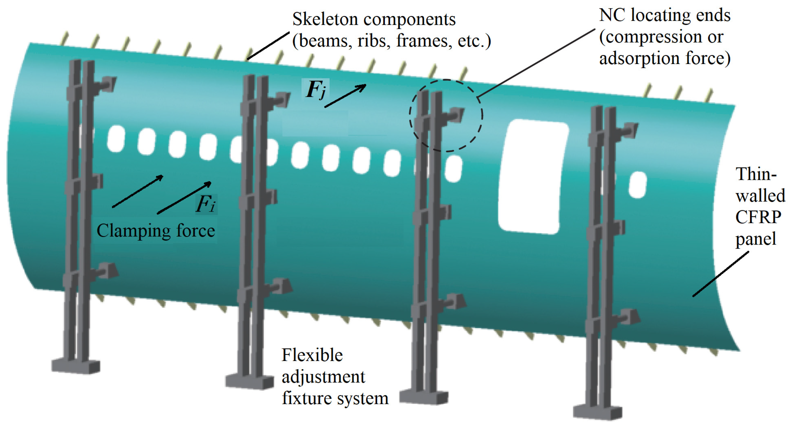
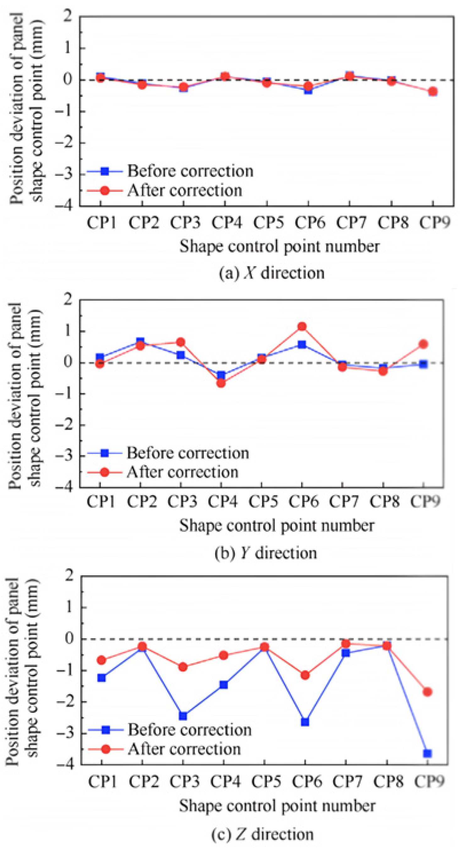
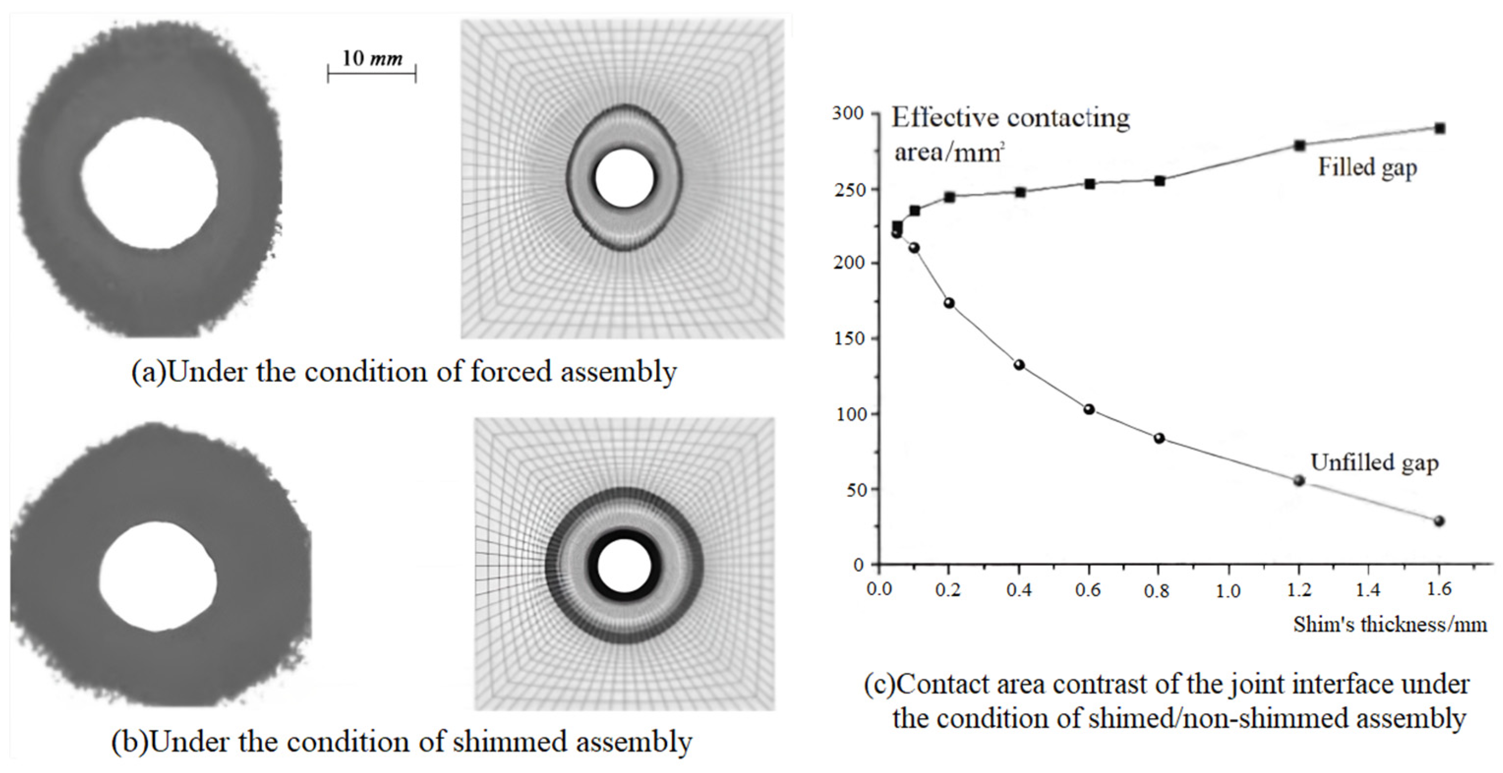
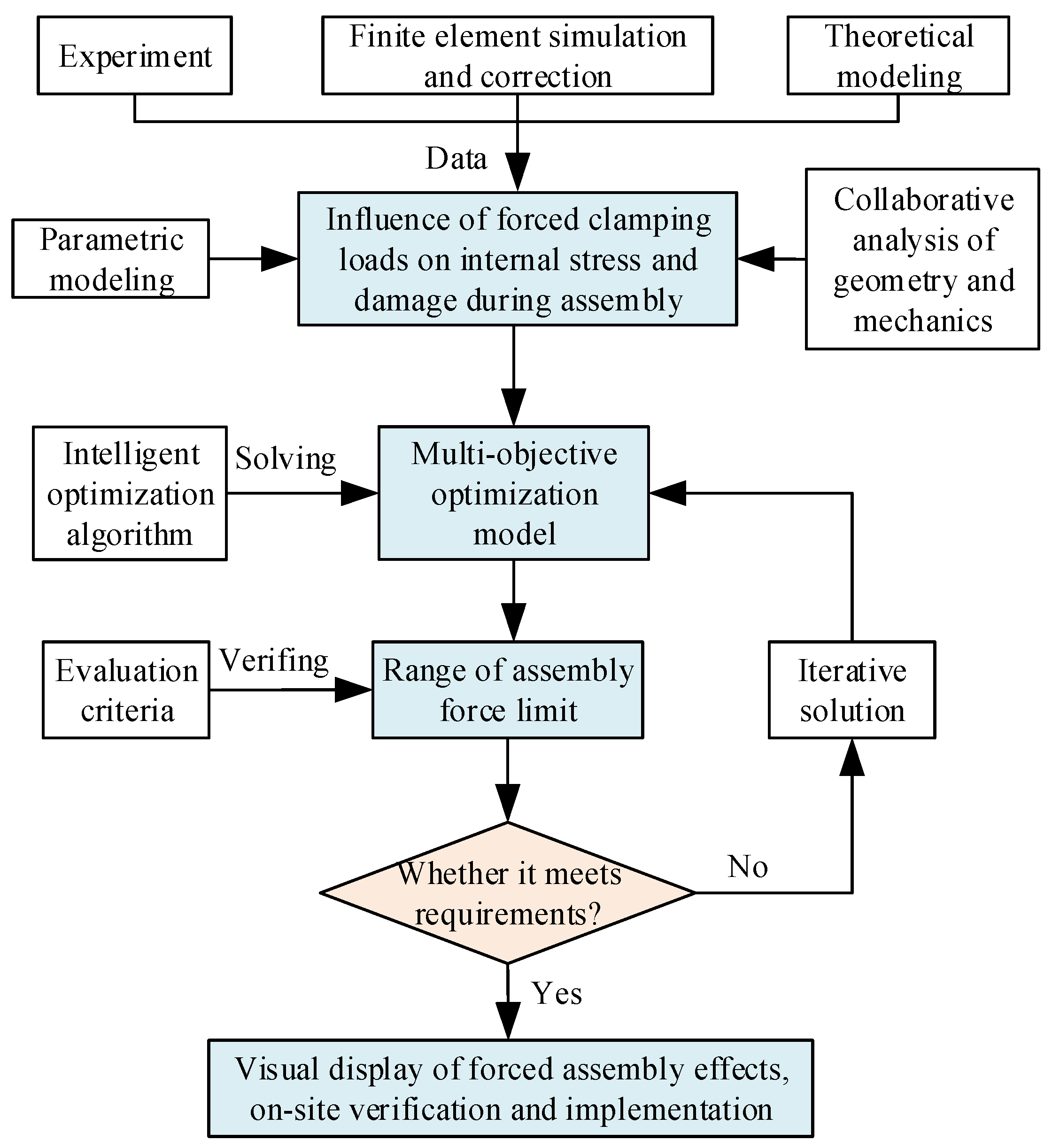
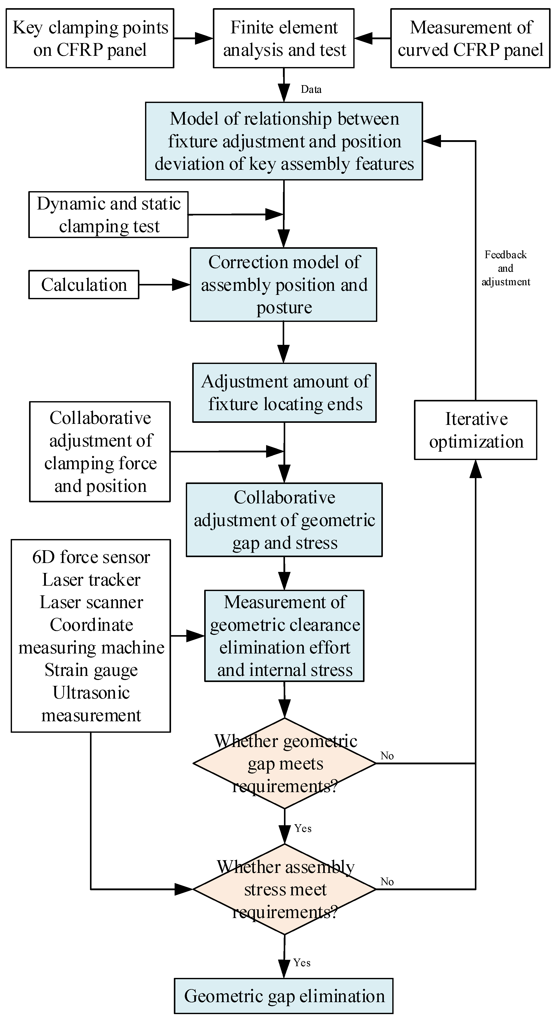
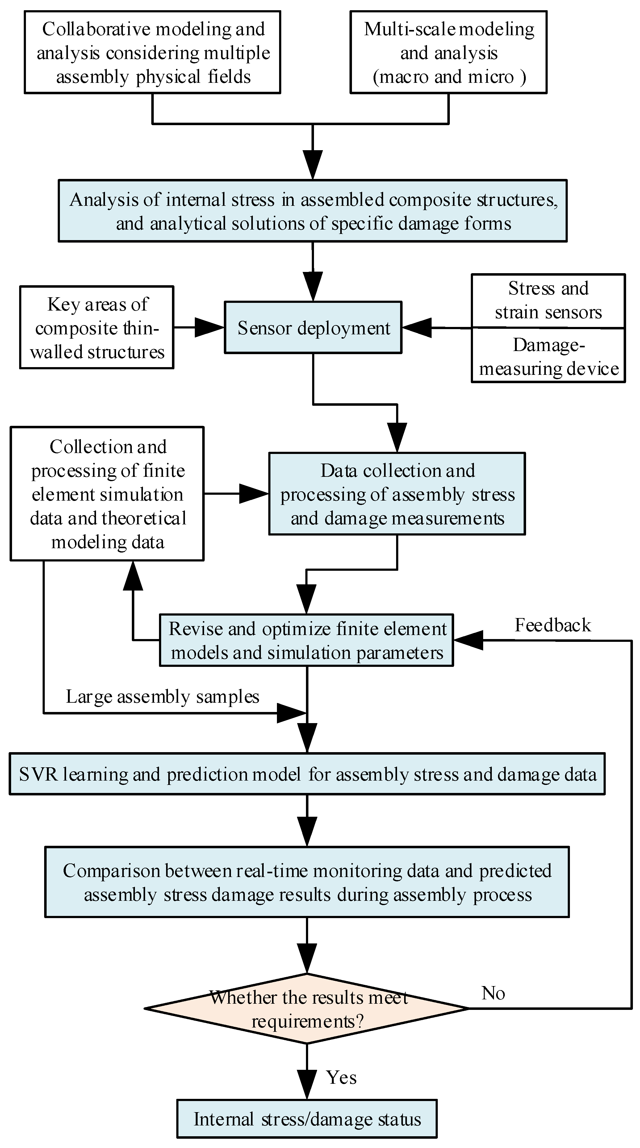
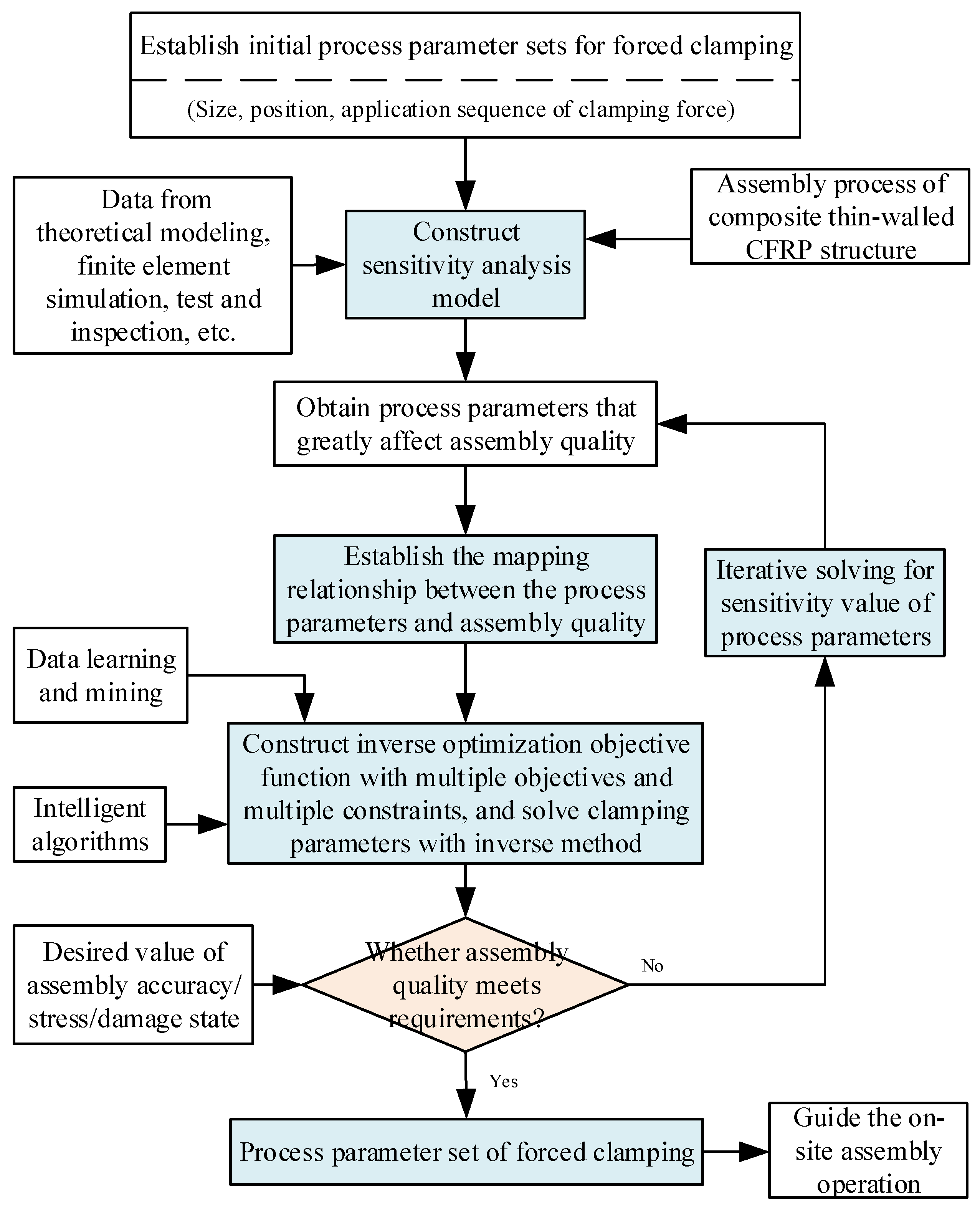
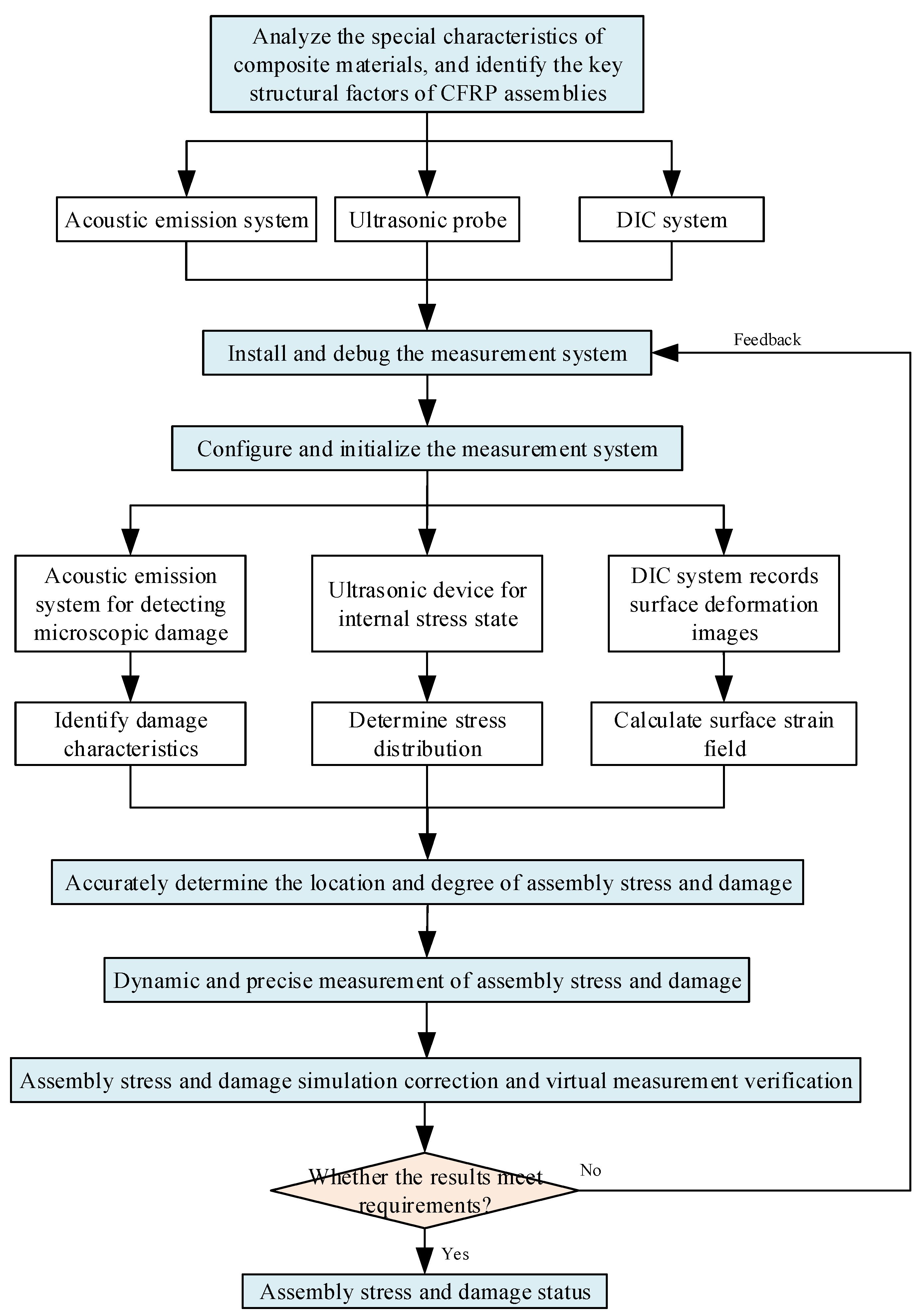
Disclaimer/Publisher’s Note: The statements, opinions and data contained in all publications are solely those of the individual author(s) and contributor(s) and not of MDPI and/or the editor(s). MDPI and/or the editor(s) disclaim responsibility for any injury to people or property resulting from any ideas, methods, instructions or products referred to in the content. |
© 2025 by the authors. Licensee MDPI, Basel, Switzerland. This article is an open access article distributed under the terms and conditions of the Creative Commons Attribution (CC BY) license (https://creativecommons.org/licenses/by/4.0/).