Abstract
The influence of inflow angle on the stall characteristics of a vertical axial flow pump is investigated numerically by solving the unsteady Reynolds-averaged Navier–Stokes equations. The study predicts both performance parameters and internal flow structures under varying inflow conditions. It is found that as the deflection angle decreases, both the critical and deep stall points shift toward higher flow rates. For the −30° scheme, the design efficiency and design head decrease by 16.27% and increase by 19.59%, respectively, compared to the 0° scheme. As stall develops, an axisymmetric blockage region forms at the impeller inlet, which reduces axial velocity and increases the impeller’s angle of attack. Under design conditions, a smaller deflection angle exacerbates boundary layer separation near the blade leading edge, thereby weakening the local work capacity and intensifying turbulent dissipation. Furthermore, although a reduced deflection angle promotes an earlier onset of stall, it also leads to a decrease in the instability intensity of the stall flow field. These results reveal a critical trade-off: while a smaller deflection angle promotes an earlier stall onset, it effectively mitigates the intensity of stall instability, providing crucial guidance for optimizing the hydraulic design and operational stability of vertical axial flow pumps.
1. Introduction
Vertical axial-flow pumps are high-capacity, low-head water conveyance systems [1,2] extensively employed in interregional water transfer [3], agricultural irrigation, flood control [4], and drainage applications. Rotating stall, a common flow instability phenomenon in pumps [5], typically manifests within the low-flow operating range of 0.4–0.6 times the design flow rate. Once established, this stall flow pattern causes precipitous declines in pump head and efficiency, accompanied by significant increases in operational noise and pulsation amplitude [6,7]. In severe cases, stall conditions may induce blade or bearing fractures, potentially leading to complete pump station failure. Although vertical axial-flow pumps normally operate within their high-efficiency range, seasonal water-level variations occasionally necessitate low-flow operation. Consequently, elucidating the formation mechanism and progression of stall in vertical axial-flow pumps and accurately predicting the critical stall point hold significant engineering value for ensuring operational safety and mitigating potential hazards.
The intrinsic mechanism of stall conditions can be attributed to a substantial increase in the impeller inflow angle under low-flow operating conditions [8], which significantly exceeds the blade inlet angle and subsequently triggers flow separation on the airfoil surface, while the pronounced pressure differential between the blade surfaces drives the formation of large-scale tip leakage vortices that further evolve into counter-rotating secondary structures upon interaction with the main flow; additionally, the low circumferential velocity near the hub promotes the development of circumferential backflow vortices. These three vortex types (flow separation vortices, tip leakage vortices with their secondary structures, and hub backflow vortices) mutually interact and coalesce into large-scale vortex clusters, causing localized impeller passage blockage that forces fluid deviation into adjacent channels, disrupting flow axisymmetry [9] and resulting in high-pressure zones in some passages and low-pressure zones in blocked ones [10]. Within the stall region of the head-flow curve, the local maximum and minimum points with zero slope are defined as critical and deep stall points, respectively. With advancing computational fluid dynamics (CFD), numerical simulation has become vital for stall flow field analysis, enabling systematic examination of geometric parameter effects [11]: Ji et al. identified tip leakage vortices as the primary energy dissipation source under stall conditions, noting that appropriate impeller blade thickening [12] or optimized tip clearance geometries (e.g., Bulge_Tip and Double_Rib_Tip) [13] can delay stall onset and narrow its operating range, though excessive thickening or improper clearance design proves counterproductive, while increasing blade number in mixed-flow pumps improves design-point efficiency but deteriorates low-flow performance, shifting the critical stall point toward higher flow and compromising operational stability [14]. Building on mechanistic insights into single geometric parameter effects [15], structural optimization has achieved notable progress. Li et al. [16] integrated design of experiments (DOE), surrogate modeling, and optimization algorithms to redesign axial-flow pump passages for enhanced stall performance, and Nguyen et al. [17] similarly optimized guide vane geometry to effectively suppress internal stall vortices and reduce pressure pulsation. It must be emphasized, however, that current stall characterization relies predominantly on uniform inflow conditions, providing a valuable theoretical framework yet being constrained by this idealized assumption without fully accounting for non-uniform inflow effects prevalent in practical applications.
Unfortunately, due to constraints in civil engineering layout, the forebay of vertical axial flow pumps is often insufficient in length, leading to the formation of an inflow deflection angle at the pump inlet [18,19]. This subjects the impeller to non-uniform inflow conditions, a problem that has been extensively studied in various turbomachinery for its complex impacts on the internal flow field and operational stability. For instance, research on reactor coolant pumps by Long et al. [20,21] revealed that specific inlet channel geometries can induce non-uniform entry flow, which not only significantly impairs the pump’s energy conversion capability but also causes pronounced asymmetry in pressure and velocity distributions within the impeller, accompanied by complex vortex structures across all flow passages. Similarly, in a study on centrifugal pumps, Yuan et al. [22] demonstrated that a 90° bend-induced non-uniform inflow interacts with the main impeller flow, exacerbating flow separation and multi-vortex mixing, and shifting the dominant frequency of impeller inlet pressure pulsation from blade-passing frequency to twice this value. Research by Zheng et al. [23] on mixed-flow pumps further demonstrated that different inflow deflection angles, which directly induce non-uniform impeller entry, significantly alter pump performance; their results showed that as the deflection angle increases, the best efficiency point shifts toward higher flow rates, reducing efficiency under low-flow conditions while improving it at high flows, while the non-uniform inflow also intensifies the vortex structures generated by rotor-stator interaction between the impeller and guide vanes. Furthermore, Kan et al. [24] observed under reverse power generation conditions in axial-flow pumps that non-uniform impeller inflow markedly disrupts impeller force equilibrium and amplifies radial force fluctuations, particularly under off-design operations. In summary, the isolated effect of the inflow angle remains underexplored [25,26], despite its significant impact on operational stability through altered operating points, increased pressure amplitudes, and complex vortex structures.
Previous studies have extensively characterized stall under idealized, uniform inflow; however, a quantitative understanding of how non-uniform inflow from deflection angles influences stall inception and development is absent. This study addresses this gap by systematically examining three distinct inflow deflection angles and their effects on stall formation mechanisms and associated flow field structures. Through numerical solutions of the Unsteady Reynolds-Averaged Navier–Stokes equations (URANS), the performance characteristics and internal flow fields under both design and stall conditions are thoroughly examined. The spatial velocity distribution at the impeller inlet under each deflection scheme is comparatively analyzed to reveal how non-uniform inflow conditions alter the flow incidence and energy characteristics. Furthermore, the intensity of stall vortices in different regions of the impeller is quantitatively evaluated using characteristic parameters based on shear strain rate, Static pressure coefficient, turbulent kinetic energy and turbulence eddy dissipation to establish precise correlations between deflection angles, vortex evolution patterns, and performance deterioration. The findings provide theoretical insights into stall suppression and operational optimization, offering practical guidance for the hydraulic design of vertical axial-flow pumps under complex inflow environments.
2. Research Methods
2.1. Three-Dimensional Model
This study investigates a vertical axial flow pump system, which is composed of an elbow-shaped inlet section, an axial flow impeller, guide vanes, and an elbow-shaped outlet section, as illustrated in Figure 1. The impeller comprises 3 blades with a hub diameter of 120 mm and an outer diameter of 300 mm. The guide vane assembly consists of 6 blades with a hub diameter of 108 mm. The pump is designed with the following performance parameters: a flow rate of 0.308 m3/s, a head of 4.3 m, an efficiency of 77.3%, and a rotational speed of 1340 r/min.
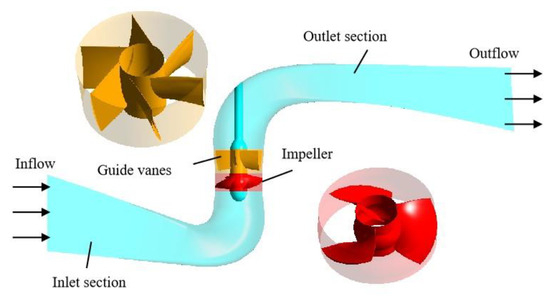
Figure 1.
Three-dimensional model model of computational domain.
2.2. Numerical Simulation
To accurately capture the internal vortex structures under stall conditions, the entire computational domain was meshed with hexahedral grids. The inlet and outlet sections were meshed in CFD ICEM, and the impeller and guide vanes domains were handled in TurboGrid, as shown in Figure 2. Grid independence was established with a final mesh of 5.192 million nodes. This determination was based on the criterion that the simulated pump head exhibited a change of less than 2% once the grid count exceeded 5 million nodes, as shown in Table 1. The final grid sizes for the inlet channel, impeller, guide vanes, and outlet channel are 1,332,635; 1,482,432; 1,226,352; and 1,150,632 nodes, respectively. The corresponding average Y+ values for these components are 27.6, 19.4, 19.4, and 15.0, as provided in Figure 3.
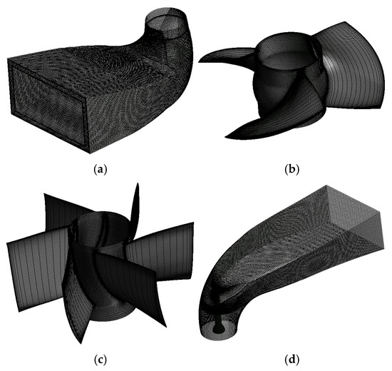
Figure 2.
The grid division of (a) inlet section, (b) impeller, (c) guide vanes and (d) outlet section.

Table 1.
Mesh independence analysis.
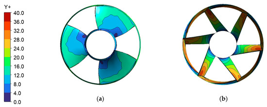
Figure 3.
The Y+ distribution of (a) impeller and (b) guide vanes.
The internal flow field and external characteristics of the vertical axial-flow pump were simulated by solving the URANS equations [27] with the SST k-omega turbulence model [28]. At the velocity inlet [29], the deflection angle (θ, relative to the horizontal) was imposed by defining the velocity components derived from the volumetric flow rate. As shown in Figure 4, the velocity components were set as follows: Vy = Vinlet × cot(θ), Vx = Vinlet × tan(θ), Vz = 0. where the inlet velocity magnitude Vinlet was given by the flow rate divided by the inlet area. The outlet was modeled as an opening with prescribed pressure and direction [30]. All walls were treated as hydraulically smooth with a no-slip condition. The rotor-stator interface between the impeller and guide vanes was handled using the “Transient Rotor Stator” model [31], and interfaces between stationary components were set to “None”. A time step of 0.000373 s, corresponding to a 3° impeller rotation per step, was adopted. The total physical time simulated was 0.448 s, equivalent to 10 full impeller revolutions.

Figure 4.
The deflection angle of vertical axial-flow pump.
3. Test Verification
To validate the numerical model, a vertical closed-loop test rig for an axial-flow pump was established, and external characteristic tests were conducted. As shown in Figure 5, the rig is structured on two levels. The upper level (3.2 m in height) is equipped with a JCL2 torque meter (range: 0–500 N·m; uncertainty: ≤0.1%) for power measurement and an EJA intelligent differential pressure transmitter (range: 0–25 m; uncertainty: ≤0.1%) for head measurement. The lower level (−2.6 m in height) contains an OPTIFLUX 2000 F electromagnetic flowmeter (range: 0–1800 m3/h; uncertainty: ≤0.2%) to measure the flow rate, which is regulated by an electric control valve.
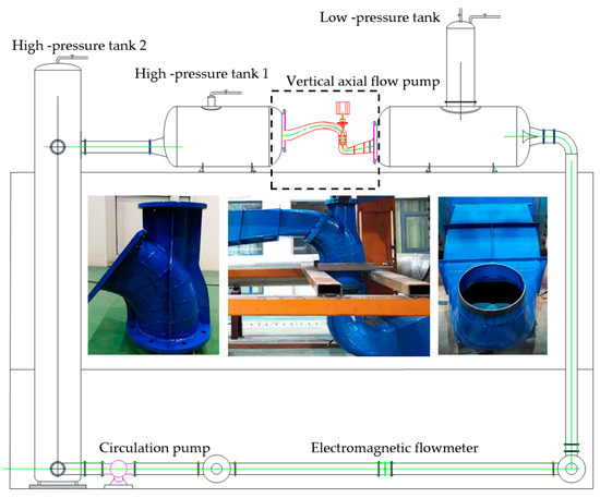
Figure 5.
Schematic of experimental test rig.
Figure 6 compares the numerical simulation results based on CFD technology with the experimental measurements. As observed, the simulated efficiency and head curves exhibit trends similar to the experimental data. In particular, the critical stall point and the deep stall point from the simulation correspond to flow rates of 0.62Qdes and 0.56Qdes, respectively, which align closely with the experimentally determined values of 0.62Qdes and 0.55Qdes. At low flow rates, both the simulated efficiency and head are slightly lower than the measured values, whereas at the design point, the simulation slightly overpredicts both parameters. At the critical stall condition, the relative errors between simulation and experiment are 4.27% for efficiency and 7.25% for head; moreover, across the entire operating range, the maximum relative errors do not exceed 4.5% for efficiency and 8.5% for head, demonstrating that the numerical simulation achieves satisfactory accuracy and reliability. The observed discrepancies primarily stem from the SST model’s simplification in simulating the anisotropic characteristics of stall vortices, measurement errors due to instrument response delay, and the actual machining errors of the impeller.
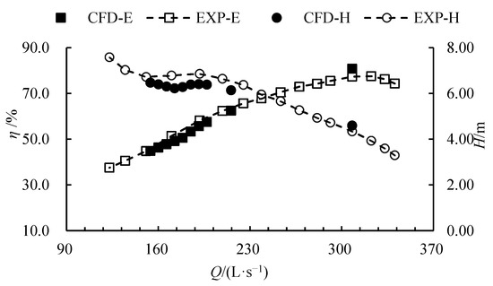
Figure 6.
External characteristic curves based on CFD and experiment.
4. Results and Discussion
4.1. Effect of Incidence Angle on Performance Characteristics Under Stall Conditions
Figure 7 illustrates the influence of three different deflection angles on the pump’s efficiency and head characteristics. As seen in Figure 7a, the overall trend of increasing efficiency with flow rate remains consistent across all deflection angles. However, at a given flow rate, a gradual decrease in the deflection angle leads to a systematic reduction in efficiency. For the −30° scheme, the design efficiency decrease by 16.27% compared to the 0° scheme. This indicates that a smaller deflection angle worsens the matching between the incoming flow and the blade inlet angle, thereby increasing hydraulic losses. Figure 7b reveals that all three schemes exhibit negative slope head curves in the low-flow region, signaling the presence of stall. Critically, as the deflection angle decreases, both the critical and deep stall points shift toward higher flow rates, significantly narrowing the stable operating range. Specifically, the critical and deep stall points shift to higher flow rates with decreasing inflow angle, from (0.62Qdes, 0.56Qdes) at 0°, to (0.72Qdes, 0.66Qdes) at −15°, and to (0.80Qdes, 0.74Qdes) at −30°; this earlier stall is concomitant with a 19.59% increase in the design head for the −30° scheme compared to the 0° scheme. This trend confirms that a reduced deflection angle deteriorates the impeller’s deflection conditions, destabilizes the internal flow field, and makes the pump more susceptible to stall at higher flow rates.
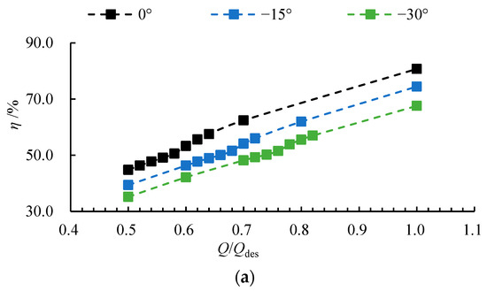
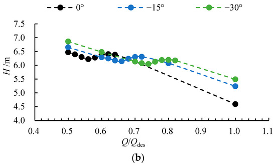
Figure 7.
The (a) efficiency-flow rate curve and (b) head-flow rate curve under three deflection angles.
4.2. Effect of Incidence Angle on the Stall Flow Field Structure at the Impeller Inlet
To elucidate the mechanisms behind the reduced efficiency and the shift of critical and deep stall points toward higher flow rates with decreasing deflection angle, an analysis of the internal flow structure at the impeller inlet section (located in Figure 8) was conducted. As revealed in Figure 9, which displays the Q-criterion and velocity vector distributions at this section, high-Q regions correspond to flow passages while low-Q zones indicate blockage. For the 0° deflection angle, the inlet section shows nearly no low-Q regions at the design condition, signifying excellent deflection and smooth passage. However, upon entering stall conditions, three axisymmetric low-Q zones emerge, indicating the formation of stall cells, which further evolve into a full-ring low-Q area near the shroud under deep stall, reflecting large-scale stall cell activity in the tip clearance region. While the −15° and −30° schemes exhibit similar flow evolution patterns, a critical observation is that even at the design condition, axisymmetric low-Q zones appear as the deflection angle decreases, demonstrating that a reduced deflection angle compromises flow stability and heightens sensitivity to internal disturbances. Consequently, under stall conditions, a smaller deflection angle promotes the premature emergence of stall cells, reduces the area of high-Q passages, and thereby impairs overall flow conductivity.
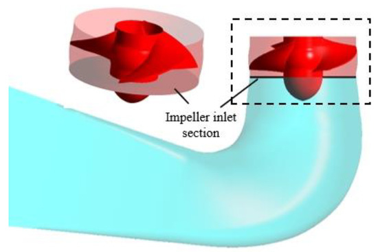
Figure 8.
Definition and location of the impeller inlet section.
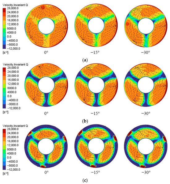
Figure 9.
Distribution of the Q-criterion at the impeller inlet under three deflection angles for (a) design condition, (b) critical stall condition, and (c) deep stall condition.
To elucidate the influence of inflow deflection angle on the flow characteristics at the impeller inlet and conduct quantitative analysis, Figure 10 presents the radial distribution of the average axial velocity at the impeller inlet section under different flow conditions. The radial coefficient Span can be calculated as follow:
where R* is the radius of the object being calculated, Rh is the hub radius, and Rs is the rim radius. At the design condition (Figure 10a), the axial velocity initially increases, then stabilizes, and finally decreases along the radial direction. Although a decrease in the inflow deflection angle does not alter this distribution pattern, it reduces the axial velocity at the same radial position, indicating that part of the axial kinetic energy is converted into circumferential flow, reflecting the degraded matching between the inflow condition and the blade inlet angle. At span = 0.02 and 0.96, the −30° scheme showed a decrease of 23.68% and 23.1% compared to the 0° scheme, respectively. Under the critical stall condition (Figure 10b), although the stall points for the −15° and −30° deflection angles occur at higher flow rates of 0.72Qdes and 0.80Qdes, respectively, their overall axial velocity distribution is similar to that of the 0° angle at lower flow rates, with slightly higher values only observed in the hub regions, indicating that a smaller deflection angle leads to flow performance degradation at larger flow rates. At Span = 0.02, the −30° scheme showed a increase of 3.21% compared to the 0° scheme. In the deep stall condition (Figure 10c), the region of decreasing axial velocity shifts notably forward to Span = 0.8–1.0, and within this region, the velocity increases as the deflection angle decreases, primarily because the deep stall point moves toward higher flow rates with reduced deflection angles. At Span = 0.94, the −30° scheme showed a decrease of 203.65% compared to the 0° scheme. This phenomenon suggests that although a smaller deflection angle narrows the high-efficiency operating range, it may alleviate local flow instability in the deep stall stage due to the increased overall flow rate.
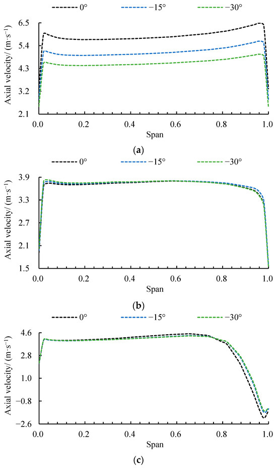
Figure 10.
Radial distribution of axial velocity at (a) design, (b) critical stall, and (c) deep stall conditions for three deflection angles.
To clarify the regional influence of inflow angle on the impeller inlet flow structure, Figure 11 presents the radial distribution of inflow angle under different operating conditions. Under design conditions (Figure 11a), the inflow angle distribution follows a characteristic pattern of initial increase, subsequent gradual decrease, and final sharp decline along the radial direction. As the inflow angle decreases, the entire radial range exhibits systematically increased inflow angles, indicating an elevated actual attack angle of the impeller that intensifies flow separation, consequently reducing efficiency while increasing head, consistent with Figure 8 findings. At Span = 0.98, the −30° scheme showed a increase of 21.11% compared to the 0° scheme. Under critical stall conditions (Figure 11b), while maintaining a similar distribution pattern to design conditions, the inflow angle variation predominantly affects the hub region (Span = 0–0.04), where the inflow angle increases significantly with decreasing inflow angle. This heightened sensitivity stems from the intensified three-dimensional corner vortex separation in the hub region induced by increased positive attack angle. Under deep stall conditions (Figure 11c), the radial distribution demonstrates complex non-monotonic behavior characterized by sequential rising, slow declining, sharp dropping, and eventual recovery. Notably, within the Span = 0.82–0.98 range where sharp decrease occurs, reduced inflow angle paradoxically induces substantial inflow angle increase. At Span = 0.98, the −30° scheme showed a increase of 24.07% compared to the 0° scheme. This phenomenon attributes to flow passage blockage from developed large-scale stall cells, which suppresses normal tip clearance leakage flow and restructures local mainstream direction, while decreased inflow angle (with increased flow rate) further reinforces the interaction between stall cells and leakage flow, ultimately causing drastic changes in local inflow conditions.
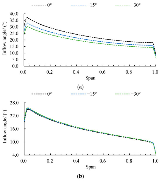
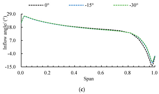
Figure 11.
Radial distribution of inflow angle at (a) design, (b) critical stall, and (c) deep stall conditions for three deflection angles.
4.3. Effect of Incidence Angle on the Stall Flow Field Structure Within an Impeller Passage
Following the clarification of how the deflection angle shapes the impeller inlet flow, a key question arises as to how this influence propagates further into the impeller and governs the structural features of the stalled flow within the passage. Figure 12 illustrates the distribution of shear strain rate on a vertical cross-section of the impeller passage under different deflection angles. Under design conditions (Figure 12a), the flow field is predominantly characterized by low shear strain rate, with elevated levels confined mainly to the blade surfaces, indicating globally stable internal flow. As the deflection angle decreases, the shear strain rate intensifies notably in the tip clearance and hub regions, suggesting the onset of boundary layer separation at multiple locations. Under critical stall (Figure 12b) and deep stall conditions (Figure 12c), the extent of the low-shear region contracts markedly, while zones of high shear strain rate expand away from the blade surfaces and shift collectively toward the impeller inlet and outlet. A further reduction in the deflection angle exacerbates this behavior. These changes can be attributed to the enhanced flow separation, strengthened secondary flow structures, and formation of large-scale stall cells that develop with increasing stall severity and reduced deflection angle. These phenomena amplify the velocity gradient between the main flow and separated regions, broaden the shear layer, and cause it to migrate with the separation zone, thereby leading to pronounced spatial expansion and streamwise shift of high shear strain rate regions. The high shear strain rate thus disrupts energy conversion, explaining the premature head drop observed in the −30° scheme compared to the 0° scheme.
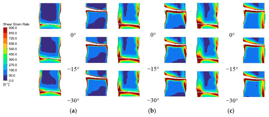
Figure 12.
Shear strain rate distribution on a blade-to-blade surface at (a) design, (b) critical stall, and (c) deep stall conditions for three deflection angles.
Figure 13 illustrates the spatial distribution of turbulent kinetic energy (TKE) on the cylindrical unfolded surface of the impeller passage under different deflection angles. Under design conditions (Figure 13a), the TKE inside the impeller remains minimal, with only a localized high-TKE zone near the trailing edge due to wake vortex shedding, indicating a highly stable internal flow field. As the deflection angle decreases, however, a distinct high-TKE region emerges at the leading edge. This occurs because the reduced deflection angle increases the actual attack angle, creating a strong adverse pressure gradient on the suction side that triggers boundary layer separation. The resulting velocity difference between the separated mainstream and the separation zone forms an unstable shear layer, which rolls up and breaks down into numerous vortex structures, causing intense velocity fluctuations and a consequent marked rise in TKE. Under critical stall conditions (Figure 13b), the high-TKE region at the leading edge expands noticeably, reflecting more severe flow separation, an effect that is further amplified by a lower deflection angle. In the deep stall regime (Figure 13c), the high-TKE zone shifts toward the impeller inlet and becomes more concentrated in distribution, albeit with significantly higher TKE levels. This shift indicates that as stall intensifies, turbulent energy becomes increasingly concentrated and dissipated within specific separation structures. Although the unstable flow region is more localized, both the local flow unsteadiness and energy dissipation intensity are considerably enhanced, underscoring the dominant role of large-scale stall structures in governing the turbulence characteristics. Consequently, the emergence of high-TKE regions signifies substantial additional energy dissipation, which directly accounts for the reduction in pump efficiency at the design operating point as the deflection angle decreases.
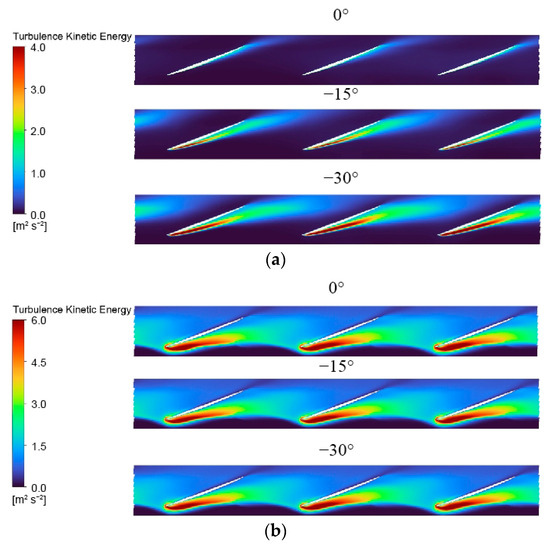
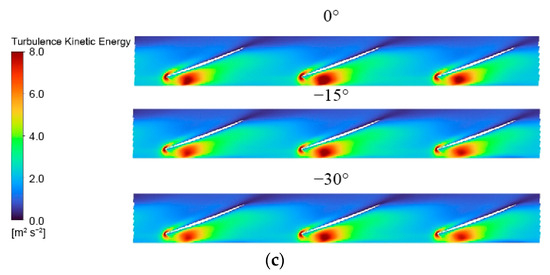
Figure 13.
Turbulent kinetic energy distribution on the blade-to-blade surface at Span = 0.98 for three deflection angles under (a) design, (b) critical stall, and (c) deep stall conditions.
To quantify the influence of the deflection angle on the impeller’s work capacity, Figure 14 presents the axial distribution of the area-averaged static pressure coefficient on a horizontal section of the impeller under three deflection angle schemes. The static pressure coefficient Cp can be calculated as follows:
where P represents the absolute pressure inside the pump, ρ is the density, and vu is the circumferential velocity. Under the design condition (Figure 14a), the static pressure coefficient first decreases, then increases, and finally stabilizes, indicating that the impeller gradually converts mechanical energy into fluid pressure energy through rotation. Near the leading edge, a brief drop in the static pressure coefficient occurs due to boundary layer separation. As the deflection angle decreases, flow stability is compromised, leading to a reduction in the impeller’s work capacity, manifested as an overall decrease in the static pressure coefficient at the same axial positions. Under both critical stall (Figure 14b) and deep stall conditions (Figure 14c), the overall trend of the static pressure coefficient distribution remains similar. However, within the axial range of 0–0.2, the static pressure coefficient increases noticeably with a reduced deflection angle. The −30° scheme showed maximum increase of 6.02% and 8.13% compared to the 0° scheme under critical stall and deep stall, respectively. Critically, the abrupt and anomalous rise in the static pressure coefficient at the mid-axial position signifies severe flow blockage. This disruption to the orderly pressure recovery process confirms that both a decreasing deflection angle and the progression of stall lead to a marked degradation in the impeller’s work capacity and a consequent drop in head.
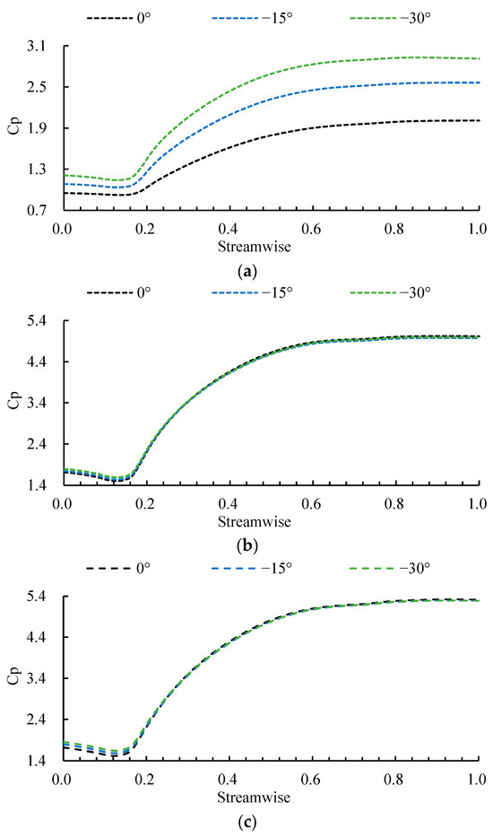
Figure 14.
Static pressure coefficient along the impeller axial direction for three deflection angles at (a) design, (b) critical stall, and (c) deep stall conditions.
Figure 15 illustrates the axial distribution of the area-averaged turbulence eddy dissipation (TED) on the horizontal section of the impeller under three deflection angle configurations, aiming to investigate the influence of deflection angle on energy dissipation. Under the design condition (Figure 15a), the TED initially rises and then declines along the axial direction. A reduction in the deflection angle leads to a noticeable increase in TED within the axial range of 0–0.2, indicating that the energy dissipation induced by boundary layer separation intensifies significantly as the deflection angle decreases, resulting in flow destabilization and heightened sensitivity to deflection variations. At Span = 0.21, the −30° scheme showed a increase of 141.13% compared to the 0° scheme. Under both critical stall (Figure 15b) and deep stall (Figure 15c) conditions, the overall trend of the TED curve remains consistent, though the dissipation level is substantially higher across the entire domain. Moreover, a decrease in the deflection angle results in a slight decrease in the peak value of TED in these regimes. Figure 14 and Figure 15 illustrate that although a decrease in the deflection angle can cause the stall condition to occur earlier, the instability intensity of the flow field will slightly decrease.
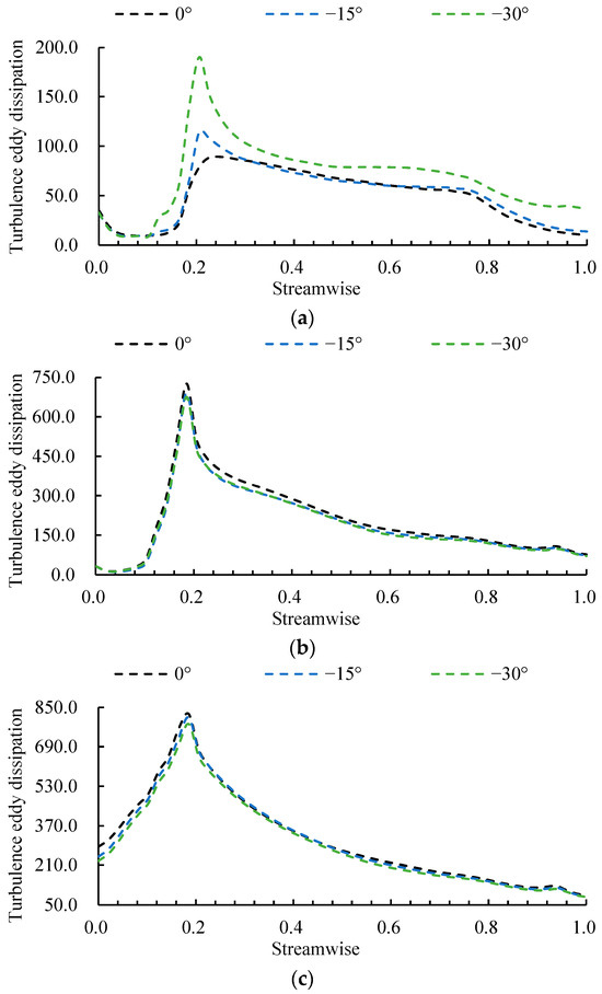
Figure 15.
Turbulence eddy dissipation along the impeller axial direction for three deflection angles at (a) design, (b) critical stall, and (c) deep stall conditions.
5. Conclusions
This study systematically investigated the performance and internal flow characteristics of a vertical axial-flow pump under three deflection angles by solving the unsteady Reynolds-averaged Navier–Stokes equations. The influence of the deflection angle was analyzed under design, critical stall, and deep stall conditions. The main conclusions are as follows:
- (1)
- A decreased deflection angle reduces pump efficiency but increases the head at the same flow rate. Consequently, both critical and deep stall points shift toward higher flow rates, which significantly narrows the pump’s high-efficiency operating range. This trade-off is exemplified by the −30° scheme, which exhibits a 16.27% decrease in design efficiency alongside a 19.59% increase in design head compared to the 0° scheme.
- (2)
- Compared with the design condition, critical and deep stall conditions induce a circumferentially uniform flow blockage at the impeller inlet. This, in turn, reduces the axial velocity and increases the actual angle of attack. A decreased deflection angle promotes the earlier formation of this blockage at higher flow rates. Quantitatively, under the design condition at spans of 0.02 and 0.96, the axial velocity for the −30° scheme is 23.68% and 23.1% lower, respectively, than that of the 0° scheme.
- (3)
- A decreased deflection angle intensifies the stall process by amplifying the sensitivity of leading-edge separation, tip leakage flow, and the hub vortex. It also aggravates mid-axial flow blockage, as evidenced by a 6.02–8.13% higher static pressure coefficient in the −30° scheme versus the 0° scheme, which disrupts pressure recovery and degrades the impeller’s work capacity. This leads to a critical trade-off: while a smaller angle hastens stall inception, it paradoxically yields a less unstable stall flow field.
Based on these findings, we recommend increasing the deflection angle of pump inlet and emphasizing low-flow optimization to suppress leading-edge separation and enhance stability when a small deflection angle is persistent. It should be noted that the current findings, while insightful, are based on a single impeller geometry and steady inflow deflection. Future studies should thus transition to dynamic inflow conditions and a wider array of geometries to fully unravel transient stall dynamics and build a comprehensive design framework.
Author Contributions
Conceptualization, F.M.; methodology, F.M. and Q.H.; software, F.M., Q.H. and J.L. (Jinhe Liu); validation, F.M., Q.H. and J.L. (Jiaxing Lu); formal analysis, F.M. and Y.L.; investigation, F.M.; resources, F.M. and Y.L.; data curation, F.M. and G.Z.; writing—original draft preparation, F.M.; writing—review and editing, F.M., G.Z. and J.L. (Jinhe Liu); visualization, F.M. and J.L. (Jinhe Liu); supervision, F.M.; project administration, F.M.; funding acquisition, F.M. and J.L. (Jiaxing Lu). All authors have read and agreed to the published version of the manuscript.
Funding
This research was funded by the Open Research Subject of Key Laboratory of Fluid Machinery and Engineering (Xihua University), Sichuan Province (grant number LTJX-2025003). Changzhou Science and Technology Project, (grant number CJ20250093).
Data Availability Statement
Data is contained within the article.
Conflicts of Interest
The authors declare no conflicts of interest.
Nomenclature
The following nomenclatures are used in this manuscript:
| URANS | Unsteady Reynolds-Averaged Navier–Stokes |
| H | Head |
| E | Efficiency |
| θ | Inflow deflection angle |
| η | Efficiency |
| Qdes | Design flow rate |
| EXP | Experiment |
| CFD | Computational fluid dynamics |
| R* | The radius of the object being calculated. |
| Rh | Hub radius |
| Rs | Rim radius |
| Span | Radial coefficient |
| Streamwise | Axial coefficient |
| TKE | Turbulent kinetic energy |
| Absolute pressure | |
| Density | |
| Circumferential velocity | |
| Cp | Static pressure coefficient |
| TED | Turbulence eddy dissipation |
References
- Yang, F.; Lin, Z.; Li, J.; Nasr, A.; Cong, W.; Li, C. Analysis of internal flow characteristics and structure optimization of vertical submersible axial flow pump device. Adv. Mech. Eng. 2022, 14, 16878132221100641. [Google Scholar] [CrossRef]
- Jiao, H.; Shan, J.; Yang, G.; Wang, M.; Chen, S. Comparison of the shutdown transitions of the full-flow pump and axial-flow pump. J. Mar. Sci. Eng. 2023, 11, 2129. [Google Scholar] [CrossRef]
- Yang, F.; Chang, P.; Cai, Y.; Lin, Z.; Tang, F.; Lv, Y. Analysis of energy loss characteristics of vertical axial flow pump based on entropy production method under partial conditions. Entropy 2022, 24, 1200. [Google Scholar] [CrossRef]
- Yang, F.; Jiang, D.; Yuan, Y.; Lv, Y.; Jian, H.; Gao, H. Influence of rotation speed on flow field and hydraulic noise in the conduit of a vertical axial-flow pump under low flow rate condition. Machines 2022, 10, 691. [Google Scholar] [CrossRef]
- Zhou, Z.; Li, H.; Chen, J.; Li, D.; Zhang, N. Numerical simulation on transient pressure pulsations and complex flow structures of a ultra-high-speed centrifugal pump at stalled condition. Energies 2023, 16, 4476. [Google Scholar] [CrossRef]
- Wéber, R.; Hős, C. Experimental and numerical analysis of hydraulic transients in the presence of air valve. Period. Polytech. Mech. Eng. 2018, 62, 1–9. [Google Scholar] [CrossRef]
- Lu, J.; Wang, Y.; Wang, B.; Zhou, Y.; Liu, X.; Si, Q. Study on the vibration characteristics induced by rotating stall in a centrifugal pump based on improved variational mode decomposition. Flow Meas. Instrum. 2025, 102, 102761. [Google Scholar] [CrossRef]
- Tang, Y.; Wang, F.; Wang, C.; Ye, C.; Qu, Q.; Xu, J. Investigation on the influence of seal clearance leakage on the rotating stall characteristics for a centrifugal pump. Phys. Fluids 2024, 36, 025176. [Google Scholar] [CrossRef]
- Zhao, Z.; Song, W.; Jin, Y.; He, L. Numerical study on flow stall and kinetic energy conversion of low-specific-speed centrifugal pump. Phys. Fluids 2023, 35, 044104. [Google Scholar]
- Feng, J.; Ge, Z.; Yang, H.; Zhu, G.; Li, C.; Luo, X. Rotating stall characteristics in the vaned diffuser of a centrifugal pump. Ocean. Eng. 2021, 229, 108955. [Google Scholar] [CrossRef]
- Ji, L.; Li, Y.; Li, W.; Li, S.; Yang, Y.; Yang, Y.; Li, H.; Agarwal, R.K. Investigation of vortex dynamics diagnosis in the stall state of mixed-flow pump with blade gap size effect. J. Braz. Soc. Mech. Sci. Eng. 2023, 45, 395. [Google Scholar] [CrossRef]
- Ji, L.; Li, W.; Shi, W.; Tian, F.; Agarwal, R. Effect of blade thickness on rotating stall of mixed-flow pump using entropy generation analysis. Energy 2021, 236, 121381. [Google Scholar] [CrossRef]
- Ji, L.; Li, S.; Li, W.; Huang, Y.; Shi, W.; Li, H.; Yang, Y.; Agarwal, R.K. Study on passive suppression method of rotating stall in mixed-flow pump: Using different impeller rim structures. Proc. Inst. Mech. Eng. Part A J. Power Energy 2023, 237, 965–984. [Google Scholar] [CrossRef]
- Ji, L.; Li, W.; Shi, W.; Tian, F.; Li, S.; Agarwal, R. Influence of different blade numbers on the performance of “saddle zone” in a mixed flow pump. Proc. Inst. Mech. Eng. Part A J. Power Energy 2022, 236, 477–489. [Google Scholar] [CrossRef]
- Lu, D.; Li, W.; Li, S.; Ji, L.; Yang, Y. Research on the relationship between stall propagation and flange leakage of mixed-flow pumps. Water 2022, 14, 1730. [Google Scholar] [CrossRef]
- Li, J.; Zhang, R.; Xu, H.; Feng, J. Multi-condition design optimization of groove flow control technique in an axial-flow pump. Int. J. Turbo Jet-Engines 2021, 40, s17–s32. [Google Scholar] [CrossRef]
- Nguyen, D.A.; Lee, H.J.; Kim, S.; Choi, B.-L.; Choi, D.-H.; Kim, G.S.; Sun, S.; Kim, J.-H. Multiobjective hydraulic optimization of the diffuser vane in an axial flow pump. Phys. Fluids 2024, 36, 075125. [Google Scholar] [CrossRef]
- Zheng, Y.; Li, Y.; Zhu, X.; Xu, X.; Meng, F. Numerical investigation of entropy hydraulic loss analysis and vortical structure suppression in mixed flow pump device under lateral inflow. Proc. Inst. Mech. Eng. Part E J. Process Mech. Eng. 2023, 237, 1529–1545. [Google Scholar] [CrossRef]
- Zheng, Y.; Gu, Z.; Li, Y.; Zhu, X.; Meng, F.; Wang, M. Entropy production analysis for energy dissipation of a vertical mixed-flow pump device under asymmetric inflow conditions. Proc. Inst. Mech. Eng. Part C J. Mech. Eng. Sci. 2022, 236, 10426–10439. [Google Scholar] [CrossRef]
- Yun, L.; Zhenguo, W.; Mingyu, Z.; Yuan, X. Research on the transient flow and vortex structure evolution mechanism of reactor coolant pump under non-uniform inflow. Ann. Nucl. Energy 2025, 217, 111346. [Google Scholar] [CrossRef]
- Long, Y.; Tian, C.; Zhang, M.; Guo, X. Research on flow characteristics of reactor coolant pumps under non-uniform inflow. Ann. Nucl. Energy 2025, 213, 111109. [Google Scholar] [CrossRef]
- Yuan, Y.; Fang, Y.; Tang, L. Effects of non-uniform elbow inflow on the unsteady flow and energy development characteristics of a centrifugal pump. Phys. Fluids 2023, 35, 015152. [Google Scholar] [CrossRef]
- Zheng, Y.; Li, Y.; Zhu, X.; Sun, D.; Meng, F. Influence of asymmetric inflow on the transient pressure fluctuation characteristics of a vertical mixed-flow pump. Proc. Inst. Mech. Eng. Part A J. Power Energy 2022, 236, 1518–1532. [Google Scholar] [CrossRef]
- Kan, K.; Zhang, Q.; Xu, H.; Feng, J.; Song, Z.; Cheng, J.; Binama, M. Investigation of non-uniform inflow effects on impeller forces in axial-flow pumps operating as turbines. Water 2024, 16, 1428. [Google Scholar] [CrossRef]
- Savcı, İ.H.; Şener, R.; Duman, İ. A study of signal noise reduction of the mass air flow sensor using the flow conditioner on the air induction system of heavy-duty truck. Flow Meas. Instrum. 2022, 83, 102121. [Google Scholar] [CrossRef]
- Şener, R.; Demir, M.E. Heat transfer and flow characteristics of a novel turbulator design in heat exchanger: Experimental and numerical analysis. Proc. Inst. Mech. Eng. Part A J. Power Energy 2024, 238, 1228–1237. [Google Scholar] [CrossRef]
- Li, S.; Luan, Y.; Xu, Y.; Liu, X.; Yang, F.; Xu, G. Numerical analysis of pressure fluctuation characteristics of axial flow pump device of edge pump unit in multi-unit pumping station. AIP Adv. 2024, 14, 075311. [Google Scholar] [CrossRef]
- Deng, E.; Yue, H.; Ni, Y.Q.; He, X.H.; Yang, W.C.; Chen, Z.W. Wake dynamic characteristics of windproof structures in embankment–bridge sections along a high-speed railway under natural strong crosswinds. Phys. Fluids 2023, 35, 055109. [Google Scholar]
- Shi, W.; Xie, B.; Ni, C.; Yu, X.; Chai, Y.; Shi, L. Numerical Simulation and Model Test on Pressure Fluctuation and Structural Characteristics of Lightweight Axial Flow Pump. Processes 2024, 12, 2369. [Google Scholar] [CrossRef]
- Meng, F.; Li, Y.; Li, M.; Ning, C. Investigation of Blade Root Clearance Flow Effects on Pressure Fluctuations in an Axial Flow Pump. Machines 2025, 13, 733. [Google Scholar] [CrossRef]
- Wang, H.; Wu, X.; Xu, X.; Bian, S.; Meng, F. Size Effect on Energy Characteristics of Axial Flow Pump Based on Entropy Production Theory. Machines 2025, 13, 252. [Google Scholar] [CrossRef]
Disclaimer/Publisher’s Note: The statements, opinions and data contained in all publications are solely those of the individual author(s) and contributor(s) and not of MDPI and/or the editor(s). MDPI and/or the editor(s) disclaim responsibility for any injury to people or property resulting from any ideas, methods, instructions or products referred to in the content. |
© 2025 by the authors. Licensee MDPI, Basel, Switzerland. This article is an open access article distributed under the terms and conditions of the Creative Commons Attribution (CC BY) license (https://creativecommons.org/licenses/by/4.0/).