Abstract
Due to their compact dimensions, high torque density, high efficiency, and superior flux-weakening capabilities, permanent magnet synchronous machines with tooth-coil winding (TC-PMSMs) are highly suitable for low-power electric transportation applications. This study incorporates the actual duty cycle of an electric motorcycle in the optimization of the slot number for the drive machine. The proposed methodology addresses the shortcomings of conventional design strategies, which typically consider only a limited set of operating points, leading to suboptimal round-trip efficiency under real driving conditions. Firstly, the influence of slot number on torque output, electromagnetic losses, and flux-weakening performance is examined for 10-pole TC-PMSMs using finite element analysis. Subsequently, the optimal slot number is identified by integrating the real duty cycle of the drive motor into the evaluation. To verify the accuracy and effectiveness of the analytical results and design approach, prototypes of stator assemblies with varying slot numbers were fabricated and experimentally tested.
1. Introduction
Permanent magnet synchronous machines featuring tooth-coil winding (TC-PMSMs) have gained significant prominence in applications, where spatial limitation and energy efficiency are paramount [1]. Such applications include servo drives, wind power generation [2], robotics, and electric propulsion [3]. This prominence is largely due to several critical advantages, including compact size, high energy conversion efficiency [4], and enhanced torque density. Within these fields, TC-PMSMs typically operate predominantly at low-speed regimes [5,6]. To enhance performance, designers often increase the number of slots and poles, thereby simultaneously improving torque output and machine efficiency.
Nonetheless, the fractional slot configuration permits a broad spectrum of feasible pole/slot combinations [7,8], even when the number of poles and electromagnetic frequency are restricted by application-specific requirements [9]. As illustrated in Figure 1, three-phase TC-PMSMs with two-layer windings demonstrate 13 viable pole/slot combinations that achieve a fundamental winding factor exceeding 0.72, within the range of 12 poles and 18 slots. While this expansive design space offers considerable flexibility, it also introduces substantial challenges in the design process, as many configurations exhibit similar electromagnetic properties, such as torque density and efficiency. This similarity complicates the selection process during the initial design stage. Therefore, it is imperative to apply multi-objective evaluation methodologies to discern the optimal configuration tailored to specific operational constraints and performance objectives [10,11,12].
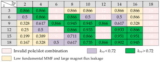
Figure 1.
Fundamental winding factors for combinations within the range of 18 poles and 18 slots.
Given the broad spectrum of feasible combinations, it is essential to undertake systematic comparative analyses [13,14,15]. Previous studies have explored the impact of pole/slot combinations on various performances, including electromagnetic characteristics such as torque density [16], torque ripple [17], electromagnetic losses [18], winding arrangements [19,20], magnetomotive force (MMF) harmonic [21], flux-weakening capability [22,23], and fault tolerance [24]. Additionally, factors such as thermal behavior and vibration/noise have been considered [6,25,26]. Nonetheless, a key limitation of these investigations is their predominant focus on discrete operating points, which may neglect the actual operational duty cycle of the drive machine. Furthermore, the reliability and extensibility of existing comparative analyses is undermined by inconsistencies in various machine design parameters. Variations in winding configurations, geometric dimensions, and even electromagnetic loading conditions across different cases introduce considerable bias. This lack of standardization compromises the generalizability of the results and conclusions, thereby impeding the derivation of definitive guidelines for selecting pole/slot combinations in new designs. Consequently, a more rigorous and systematic study employing uniform design constraints and evaluation criteria is warranted to facilitate fair and meaningful assessments that can effectively guide new developments.
This research presents an investigation of two-layer three-phase TC-PMSMs featuring a fixed pole number of 10, while systematically varying slot numbers from 9 to 18, with the objective of elucidating the underlying relationships between slot number and critical performances and the round-trip efficiency of the drive machine, and maximizing energy utilization over the entire duty cycle, thereby enhancing the overall endurance range. By maintaining a constant pole number across multiple design variants and incrementally adjusting the slot number, deterministic trends governing machine performance can be identified. The study adopts a structure, beginning with Section 2, which investigates 10-pole machines with slot numbers ranging from 9 to 18. Section 3 presents a detailed comparative analysis of three critical performance indicators: torque characteristics, overload capacity, and flux-weakening capability, the latter of which demonstrates notable sensitivity to slot number variations. Given the focus on motorcycle applications, Section 4 defines the duty cycle employed to optimize the slot number. Finite element method (FEM) is utilized to ensure precise electromagnetic field solutions. Finally, Section 5 offers experimental validation through the construction and testing of prototypes configured for motorcycle use.
2. Machine Specification and Design Constraints
2.1. Specification of Drive Machine
The initial design stage of the drive machine for an electric motorcycle demands rigorous performance criteria, particularly concerning torque density, constant power speed range, and round-trip efficiency. The specifications of the drive machine are presented in Table 1. A tooth-coil winding configuration is chosen due to its shorter end winding compared to conventional distributed winding, as well as its enhanced flux-weakening capability. Correspondingly, the rotor employs an interior V-type permanent magnet arrangement to concentrate the magnet flux, thereby achieving high torque output and elevated d-axis inductance, which further improves the flux-weakening performance.

Table 1.
Specifications and main design parameters of the drive machine.
The key performance parameters are fundamentally determined by the electromagnetic configuration, particularly the interplay between the slot number z and rotor poles number 2p. A systematic preliminary selection of the most suitable pole/slot combinations constitutes a critical initial phase in the design process. This selection is guided by the operational speed outlined in Table 1 and the feasible switching frequency of the power semi-conductor devices, aiming to achieve an optimal inverter carrier ratio. Consequently, a pole number of 10 with a carrier ratio of 8 at maximum speed is chosen, ensuring that both switching losses and rise in inverter temperature remain acceptable.
A notable constraint inherent to the V-type rotor topology is the magnetic flux leakage occurring in the magnet post and bridge regions, as illustrated in Figure 2. Minimizing this flux leakage is essential to improve flux concentration and enhance torque output. Simultaneously, it is imperative to maintain rotor structural integrity against failure induced by centrifugal forces and stress concentrations. Additionally, the rotor periphery is engineered with a non-concentric arc profile to create a non-uniform air gap, which serves to improve the sinusoidal quality of the back-electromotive force and reduce the cogging of the torque.
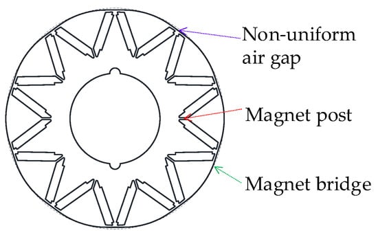
Figure 2.
The configuration of the 10-pole rotor used in all four variants.
2.2. Design Space of the Slot Number
The primary criterion involves the requirement for a high fundamental winding factor kwp when selecting the slot number z, for maximizing torque output. To clarify the underlying principles and enable a clear comparative analysis, a series of 10-pole TC-PMSMs with z ranging from nine to eighteen were chosen. This range was selected to ensure that kwp exceeds a threshold of 0.72. Consequently, the proposed pole/slot combinations include 10p9s (a TC-PMSM with ten poles, nine slots, and two-layer tooth-coil winding), 10p12s, 10p15s, and 10p18s. The specification of winding type, layer, strands of each coil turn, and conductor diameter are listed in Table 1, which are consistent across all machine configurations.
Due to constraints imposed by switching losses and thermal dissipation, the switching frequency of the power semi-conductor devices in the inverter is limited to 5 kHz. As pole number increases, the fundamental electromagnetic frequency rises, resulting in a lower carrier ratio, which is the ratio of switching frequency to fundamental current frequency, at a given rotational speed. This leads to increased current harmonic content, along with elevated torque ripple and additional losses. Therefore, combinations with a pole number greater than 14 exhibit a low carrier ratio and are therefore excluded from consideration. For illustrative purposes, Figure 3 presents a cross-sectional view of the winding layouts for 10p9s to 10p18s configurations.

Figure 3.
The coil connection pattern: (a) 10p9s; (b) 10p12s; (c) 10p15s; (d) 10p18s.
The stator dimensions—including an inner diameter Dsi of 85 mm, a stack length of 120 mm, and an outer diameter of 140 mm—are strictly maintained to isolate the influence of z. These four machines are designed with identical total series turns per phase and slot fill factor Sf of 0.65, and thus the area allocated for slots is fixed, with the remaining space distributed to the stator teeth and yoke. Then, the tooth width is designed inversely proportional to z, with the residual space determining the yoke thickness. Finally, the tooth width and yoke thickness are fine-tuned to ensure a tooth flux density of 1.40 T and a yoke flux density of 1.20 T at the rated condition. Under this approach, the yoke thickness and tooth width are almost inversely proportional to z, as illustrated in Figure 3. The slot opening is determined based on the winding machine’s tolerance requirements, allowing for the direct insertion of 10-strand, 0.8 mm conductors into the slots.
A critical factor pertains to the number of turns per individual coil, denoted as Nc. For each configuration, Nc is determined to be inversely proportional to z, as indicated in Equation (1), with the objective of maintaining an approximately constant number of series turns per phase Tph, across all four configurations. Furthermore, to ensure uniformity in performance characteristics evaluation, the number of parallel paths within each phase winding is consistently maintained at one.
Taken together, these meticulously applied winding design constraints guarantee that the phase resistance Rph, current density J, and electrical loading Aload remain consistent across all four variants when subjected to the same excitation current Im, as expressed in Equation (2).
The phase coil connections depicted in Figure 3 were established utilizing the star-of-slot method [27], with the objective of maximizing the winding factor kwp to enhance torque output and overall electromagnetic performance.
So far, it establishes a robust and consistent foundation for comparative analysis and enables a rigorous evaluation of the key performance metrics across all four variants. Essential metrics, such as torque density and flux-weakening capability—a crucial characteristic for extended high-speed operation—can be accurately determined and compared. A comprehensive discussion of these performance aspects is presented in the following sections.
3. Torque Output and Flux-Weakening Capacity
3.1. Torque Overloading Ability
As previously mentioned, the four variants are designed to have identical flux densities in both stator teeth and yoke. Consequently, the slot number z is the primary factor influencing torque output and overload capacity. Figure 4 presents the torque–current characteristics for 10p9s to 10p18s, obtained through parametric FEM. In the FEM, periodic boundary conditions were applied to reduce the model size. Specifically, the 10p12s and 10p18s employ half-models with anti-periodic boundary conditions, while the 10p15s model utilizes a one-fifth segment with periodic boundary conditions. In contrast, the 10p9s model, which lacks periodicity, uses the full geometry. For mesh generation, the circumferential step in the air gap was set to 1/90 of the arc length, corresponding to one electrical cycle. The stator and rotor components are meshed using a fixed element size. As for solution process, the convergence tolerance is set to 0.002.
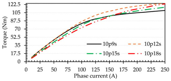
Figure 4.
The variation in torque output against the input currents using MTPA control strategy.
It is evident that 10p12s and 10p9s generate maximal torques at the rated current of 40 A when employing the maximum torque per ampere (MTPA) control strategy. This is attributed to the close proximity between pole and slot numbers, resulting in the highest winding factor kwp. In contrast, 10p15s and 10p18s exhibit lower open-circuit flux densities Boc1, due to increased magnet flux leakage relative to 10p12s and 10p9s designs. Additionally, their winding factors of 0.87 and 0.74, respectively, further diminish their torque output performance. Owing to the harmonic leakage and stator leakage inductance, the four motors exhibit a relatively low saliency ratio. Consequently, the electromagnetic torque constitutes the dominant portion of the total output torque. The reluctance torque remains subordinate, reaching a maximum of only 6.52%, across the evaluated current range, which corresponds to an MTPA angle of merely 8.93°.
However, the behavior differs significantly when operating under high current conditions that drive the stator core into magnetic saturation. A critical observation is that the torque constant progressively decreases as the current increases, attributable to the intensified effects of magnetic saturation. Notably, 10p12s and 10p18s generate nearly identical overload torque at the peak current of 250 A, both exceeding that of 10p9s. This suggests that the anti-saturation performance of 10p18s surpasses that of both 10p9s and 10p12s, despite its rated torque constant being lower than that of 10p12s. Figure 5 illustrates the magnetic flux density under a torque overload condition, when one of three-phase current reaches its peak value, revealing that the flux densities in the stator tooth and yoke are lower for 10p15s and 10p18s compared to 10p9s and 10p12s. The primary reason for the reduced magnetic saturation is the more distributed arrangement of phase coils. For instance, unlike the concentrated grouping of three coils in the 10p9s configuration, as visually confirmed in Figure 3a, the phase coils in other combinations are more widely dispersed within the stator core. This finding indicates that strategically increasing the slot number can provide a significant advantage, thereby improving the machine’s operational performance and its capacity to handle torque overload conditions.

Figure 5.
Contour plot of magnetic flux density under torque overload condition of 250 A.
3.2. Flux-Weakening Capacity
In this study, the flux-weakening capability is quantitatively assessed through the flux-weakening ratio, denoted as ζ and defined mathematically in Equation (3). Since two-dimensional FEM provides high accuracy in determining electromagnetic parameters, the comprehensive values for the d-axis inductance Ld, magnet flux linkage ψm, and the resulting flux-weakening ratio ζ are systematically presented in Table 2. It is important to note that Ld from two-dimensional FEM includes all constituent components except for the end-winding inductance Lew, which is considered negligible relative to other elements due to the inherently compact end windings and the non-overlapping arrangement of the tooth coils. Consequently, Lew is justifiably excluded from subsequent evaluations of flux-weakening performance.

Table 2.
Flux-weakening parameters calculated using two-dimensional FEM.
Regarding the magnet flux linkage ψm, as defined in Equation (4), under the constraints of uniform design parameters, as in the bracket, for 10p9s to 10p18s, it demonstrates a proportional relationship with the open-circuit flux density Boc1 and the fundamental winding factor kwp. Both Boc1 and kwp exhibit decreasing trends as the slot number z increases. Consequently, ψm experiences a significant reduction with an increasing z. On the other hand, an increase in z results in a more pronounced decrease in the D-axis inductance Ld, attributable to the simultaneous reduction in harmonic leakage inductance and stator leakage inductance, as reported in [28].
Consequently, it can be seen from Table 2 that a larger z exhibits a diminished ζ, and 10p9s achieves a most superior flux-weakening performance relative to all other examined designs, primarily as a consequence of its largest inductance. For 10p9s, ζ even exceeds one with two times rated current, signifying that TC-PMSMs with less slot possess exceptional flux-weakening capacity—a notable contrast to the integer-slot-distributed winding machines, which are generally deemed unsuitable for applications prioritizing this characteristic.
Since the flux density within the stator core, the number of poles, and the electromagnetic frequency remain constant across the four machines, iron loss shows negligible difference among them. Consequently, the optimal slot number in terms of magnetic efficiency is the one that meets the specified torque and speed demands (Te, n) while drawing the least current. Below the critical speed ωe, the MTPA control strategy is implemented. At each operating point, the current phase advance angle is determined based on inductance and flux linkage values obtained through two-dimensional FEM, thereby incorporating the effects of magnetic saturation, as described in (5) and (6).
In the flux-weakening region beyond the critical speed, the input d-axis current id and q-axis current iq are determined as follows in (6) and (7). Here, Um denotes the maximum attainable phase voltage of the inverter, which is derived from the supplied DC bus voltage Udc. Under standard modulation, the maximum AC voltage output of a three-phase full-bridge inverter is constrained by the DC bus voltage, resulting in a well-defined output voltage limit circle for any given DC voltage. When space vector pulse width modulation (SVPWM) is employed, the amplitude of the resulting phase voltage is approximately 1/√3 times the DC bus voltage. Given Udc = 270 V, the inverter employing space vector pulse width modulation is capable of providing a maximum Um of 155.2 V.
Figure 6 illustrates the torque–speed characteristics and the corresponding d-axis current required for all four machines when operated at their rated current, where the result is calculated using FEM. The data reveal that the flux-weakening performance is strongly dependent on the speed range of operation. Below the critical speed, the 10p9s, followed by the 10p12s, exhibits the broadest torque–speed envelope, indicating the most superior flux-weakening capability. The 10p12s demonstrates enhanced torque generation throughout the operational range from the critical speed up to 3850 r/min. Furthermore, within the narrow speed interval of 4400 to 5250 r/min, the 10p18s shows a marked advantage in torque production compared to the 10p12s. Examination of the current requirements of the d-axis indicates that the 10p15s and 10p18s are most efficient in the mid-speed range of 3000 r/min~4500 r/min. At higher speeds, up to 4750 r/min, the 10p18s emerges as the most efficient, while the 10p12s consistently requires a moderate level of weakening current across the entire speed spectrum.

Figure 6.
Torque–speed envelope and required d-axis current in the entire rotation speed range.
4. Driving Duty Cycle Analysis
The preceding analysis demonstrates that each slot number candidate exhibits unique performance trade-offs concerning torque output, torque overloading, and flux-weakening capability, with their respective advantages differing markedly across various speed ranges. For instance, the 10p9s may be selected when prioritizing torque and efficiency at the rated operating point. Conversely, if torque-overloading capability for vehicle start or hill-climbing scenarios are critical, the 10p12s or 10p18s configurations become preferable. However, the 10p9s demonstrates a distinct advantage when flux-weakening capability at 4500 r/min~6000 r/min is highlighted. Therefore, determining an optimal slot number based on a limited set of operating points is not rational; instead, a thorough evaluation aligned with the motor’s actual operational duty cycle is required. This section assesses the performance of each motor under a specified driving duty cycle to ascertain its overall operational efficiency. Figure 7 illustrates the motor speed and torque demands over entire duty cycle time, derived from modeling parameters including vehicle speed, mass, frontal area, wheel radius, drag coefficient, gear ratio, and rolling resistance coefficient, as recorded in Table 3. The data indicate that the motor operates across a range of speeds and torques within its maximum speed and power constraints, rather than at constant values. Additionally, it is key to note that during regenerative braking phases, the drive motor acts as a generator, supplying electrical energy back to the battery.

Figure 7.
Motor speed and torque versus time recorded during a standard test duty cycle.

Table 3.
Vehicle parameter of the electric motorcycle used to calculate torque and speed profiles.
Figure 8 illustrates the efficiency maps for 10p9s to 10p18s under both MTPA and flux-weakening control strategies, alongside the distribution of operating points derived from the test duty cycle superimposed on these maps. The data reveal that variations in the slot number result in significant difference in the size and distribution of high-efficiency regions. Notably, the 10p12s exhibits the most extensive high-efficiency area; however, its efficiency at the peak speed is inferior to that of the 10p9s. At the peak torque operating point, both 10p12s and 10p18s demonstrate superior efficiency, suggesting enhanced torque overload capabilities, which aligns with prior analyses. Additionally, within the assessed operational duty cycle, the majority of operating points are distributed over a wide speed range but at relatively low torque levels. Consequently, to optimize overall operational efficiency, the selection of slot number should prioritize ensuring that the high-efficiency region encompasses a broad speed range.
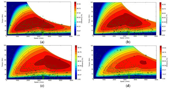
Figure 8.
Efficiency maps of the four motors and the operating point distribution of the duty cycle: (a) 10p9s; (b) 10p12s; (c) 10p15s; (d) 10p18s.
Table 4 lists the round-trip performance of the motors over the specified duty cycle, encompassing metrics such as energy consumption, mechanical power output, kinetic energy recuperated through regenerative braking, and various electromagnetic losses throughout the entire cycle. In Table 4, Emi and Emo are the sum of the input electrical energy and the output mechanical energy via motor shaft, respectively, across all motoring points of the evaluated duty cycle. Egi and Ego are the sum of the input mechanical energy at the shaft and the output electrical energy recovered from generating mode. η denotes the average efficiency that is calculated based on energy usage as total output energy divided total input energy, as in (8). Pcu, PFe, and Pm are the sum of the winding copper losses, iron loss, and magnet eddy current loss, respectively, across the entire duty cycle.

Table 4.
Round-trip performance over entire driving duty cycle.
The duty cycle duration is 4.5 min. It is important to point out that bearing losses and aerodynamic friction losses during rotation are excluded from this analysis. The findings reveal that, over the full duty cycle, the 10p12s configuration attains the highest energy utilization efficiency, followed sequentially by the 10p15s and 10p9s. This result can be attributed to the limited occurrence of operating points, characterized by high speed and high torque within the target duty cycle. The majority of operating points lie within the range of 1500 r/min to 4500 r/min and 0 to 45 Nm. Within this torque and speed domain, as depicted in Figure 4 and Figure 6, the 10p12s demonstrates comparatively superior torque output capability relative to the other candidates.
From the perspective of losses, the lower overall efficiency observed in the 10p9s and 10p18s is primarily attributable to their elevated current and copper losses. This suggests that an increase in slot number, coupled with insufficient torque output capability, detrimentally impacts efficiency at peak speed and peak torque conditions. Moreover, the 10p9s exhibits relatively higher magnet eddy current losses, which stem from its lower slot number resulting in increased MMF harmonic. These harmonics induce significant eddy current losses within the magnet. Additionally, as indicated in Table 4, under equivalent electrical frequencies and magnetic flux densities in the stator core, the iron losses across all motors display minimal variation, corroborating the validity of the previously established constraint conditions.
5. Prototyping and Experimental Validations
To validate the preceding analysis, motor prototypes featuring different slot numbers were manufactured, all utilizing a single shared 10-pole rotor, as shown in Figure 9. The motor employs a cooling system with housing fins, which facilitate forced air convection as airflow passes over the surface during vehicle operation. To improve thermal dissipation, the windings were impregnated with an epoxy resin compound. A test platform was developed, consisting of a motor coupled in a back-to-back arrangement with a powder brake. This test bench is intended to replicate the dynamic conditions of an actual driving cycle. The powder brake’s input current was modulated to achieve the desired torque profile, while the drive machine was controlled according to the specified speed trajectory of the duty cycle, keeping the mechanical power of all four motors identical.
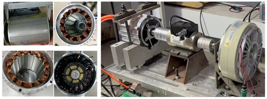
Figure 9.
The 10-pole motor rotor, stators, and back-to-back test rig.
Table 5 provides a comparative evaluation of the calculated and experimentally measured inductances and back-EMFs. The data indicate that the measured inductance is marginally higher than the calculated one, with the maximum deviation remaining under 3%. This slight discrepancy is likely attributable to stray inductance arising from coil interconnections and the terminal lines of each phase.

Table 5.
Comparison of the calculated and measured machine parameters.
Additionally, the measured back-EMF exhibits a slight reduction relative to the calculated value, as illustrated in Figure 10, with a maximum error below 4%. This difference is probably due to the somewhat diminished magnetic performance of the prototype magnets, compared to those modeled in the simulation. Collectively, the close correspondence between the measured and calculated values serves to indirectly validate the observed variation patterns of magnet flux linkage and the flux-weakening ratio as functions of slot number.


Figure 10.
The calculated and measured line EMFs: (a) 10p9s; (b) 10p12s; (c) 10p15s; (d) 10p18s.
Figure 11 illustrates the experimentally tested efficiency maps, with a peak power of 31.6 kW. The efficiency is measured under a thermal steady-state condition, with the motor housing cooled by forced air. It is to note that, due to the magnetic powder brake’s inability to simulate energy recovery, the efficiency measurements are limited to motor operation mode only. A comparison with the simulation in Figure 8 indicates that the measured efficiencies of the four motors are marginally lower than the simulated values, with a maximum efficiency decrease of 1.52%. This discrepancy is primarily attributed to the omission of some losses in simulation model, including bearing friction, windage losses, and potential stray losses. Despite this, the efficiency variation trend as a function of slot number corresponds well with the simulation outcomes, with the 10p12s demonstrating the highest efficiency and the widest high-efficiency operating range.
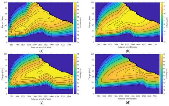
Figure 11.
Measured efficiency maps: (a) 10p9s; (b) 10p12s; (c) 10p15s; (d) 10p18s.
Table 6 presents a summary of the round-trip efficiencies under the specified driving duty cycle, which exclusively represents the motoring mode. The observed average efficiency from the tests is slightly lower than the simulated values, which is a discrepancy attributable to the factors discussed earlier. However, the effect of the slot number on round-trip efficiency remains consistent with the computational results, thereby validating both the conclusions drawn and the employed methodology. In terms of improving energy utilization efficiency, the 10p12s configuration emerges as the most favorable option, with the 10p15s as the subsequent alternative.

Table 6.
Round-trip performance with motoring mode over driving duty cycle.
6. Conclusions
This paper presents a systematic methodology for determining the optimal slot number in 10-pole TC-PMSMs for electric motorcycles, moving beyond traditional design approaches that rely on limited operating points. The findings indicate that no single slot configuration consistently outperforms others, across all performance metrics. Specifically, the 10p9s configuration exhibits superior flux-weakening capabilities, whereas the 10p18s demonstrates enhanced resistance to magnetic saturation. The evaluation of round-trip efficiency emerged as the critical determinant, with findings conclusively identifying the 10p12s configuration as the optimal design, whereby it achieved the highest average efficiency of 78.42%. This performance advantage is attributed to its balanced characteristics, which integrate a high fundamental winding factor conducive to robust torque production with an efficiency profile that aligns closely with the predominant operating points within the duty cycle. The analysis underscores the necessity of adopting a duty-cycle-focused design methodology to optimize overall energy utilization in dynamic applications such as drive motors.
Author Contributions
Conceptualization, Z.Z. and H.Y.; methodology, Y.G. and Z.Z.; simulation, Y.G. and Z.Z.; validation, Z.Z.; resources, Q.S. and H.Y.; data curation, H.O. and Y.G.; writing—original draft preparation, Y.G. and Z.Z.; writing—review and editing, Z.Z. and L.M.; supervision, H.Y. and L.M. All authors have read and agreed to the published version of the manuscript.
Funding
This research was funded in part by the National Natural Science Foundation of China (grant number 52307058), and in part by the Natural Science Foundation of Jiangsu Province (grant number BK20230322 and BK20243045), and the APC was funded by Nanjing Tech University.
Data Availability Statement
The original data produced in this study are included in the article. Further inquiries can be directed to the corresponding author.
Conflicts of Interest
Authors Qiang Sun and Zichong Zhu were employed by the company Ningbo Shenglong Group Co., Ltd. The remaining authors declare that the research was conducted in the absence of any commercial or financial relationships that could be construed as a potential conflict of interest.
References
- Liang, D.; Zhu, Z.Q.; Li, H. High-Accuracy Lumped-Parameter Thermal Modeling for Fractional-Slot Concentrated-Winding PMSMs Under Short-Circuit Fault Conditions. IEEE Trans. Transp. Electrif. 2025, 11, 9022–9034. [Google Scholar] [CrossRef]
- Rudden, I.; Li, G.-J.; Zhu, Z.-Q.; Duke, A.; Clark, R. An Investigation into the Saliency Ratio of Fractional-Slot Concentrated-Winding Generators for Offshore Wind Power. Energies 2025, 18, 2057. [Google Scholar] [CrossRef]
- Xue, H.; Zhang, Z.; Liu, Y.; Gao, H.; Lin, Q.; Lu, C.; Hua, Y. Analysis of Lightweight Dual-Rotor Yokeless-Stator PMSM for Electrified Aircraft Propulsion Considering Thermal Benefits of Heat Pipes. IEEE Trans. Transp. Electrif. 2025, 11, 11030–11040. [Google Scholar] [CrossRef]
- Abdel-Wahed, A.T.; Ullah, Z.; Abdel-Khalik, A.S.; Hamad, M.S.; Ahmed, S.; Elmalhy, N.A. Design and Finite-Element-Based Optimization for a 12-Slot/10-Pole IPM Motor with Integrated Onboard Battery Charger for Electric Vehicle Applications. Machines 2023, 11, 534. [Google Scholar] [CrossRef]
- Wu, D.; Xu, J.; Lin, H. Research on High Thrust Force Characteristics with Proper Fractional-Slot Concentrated Winding for a Ultra-Low Speed Tubular PM Linear Machine. IEEE Trans. Appl. Supercond. 2024, 34, 5206206. [Google Scholar] [CrossRef]
- Veg, L.; Kaska, J.; Skalický, M.; Pechánek, R. A Complex Study of Stator Tooth-Coil Winding Thermal Models for PM Synchronous Motors Used in Electric Vehicle Applications. Energies 2021, 14, 2395. [Google Scholar] [CrossRef]
- Wang, K.; Zhu, Z.Q.; Ombach, G.; Koch, M.; Zhang, S.; Xu, J. Electromagnetic Performance of an 18-Slot/10-Pole Fractional-Slot Surface-Mounted Permanent-Magnet Machine. IEEE Trans. Ind. Appl. 2014, 50, 3685–3696. [Google Scholar] [CrossRef]
- Wang, C.; Liu, J.; Han, J.; Zhang, Z.; Jiang, M. Analysis of Bidirectional Magnetic Field Modulation on Concentrated Winding Spoke-Type PM Machines. IEEE Trans. Transp. Electrif. 2024, 10, 6076–6086. [Google Scholar] [CrossRef]
- Aydin, M.; Demir, Y.; Yolacan, E.; Gulec, M.; El-Refaie, A.M. Design and Validation of an Unconventional 39-Slot PM Synchronous Motor with Asymmetric and Unbalanced AC Windings. IEEE J. Emerg. Sel. Top. Power Electron. 2022, 10, 1733–1744. [Google Scholar] [CrossRef]
- Yang, G.; Li, J.; Hua, W. Investigation of Electromagnetic Torque Generation Mechanism in FSCW V-IPM Machines Considering Magnetic Saturation. IEEE Trans. Transp. Electrif. 2025, 11, 6428–6440. [Google Scholar] [CrossRef]
- Chen, Z.; Liang, Z.; Liang, D.; Jia, S. Partial Demagnetization Fault Analysis and Diagnosis for Fractional Slot Concentrated Winding PMSMs Based on DQ-Axis Components. IEEE Trans. Energy Convers. 2025, 40, 1062–1072. [Google Scholar] [CrossRef]
- Yin, H.; Hua, W.; Wu, Z.; Du, J. An Efficient Rotor-Skewing Model for Mitigating Electromagnetic Vibration and Noise in Fractional-Slot Concentrated-Winding Permanent-Magnet Machines. IEEE/ASME Trans. Mechatron. 2025, 30, 818–828. [Google Scholar] [CrossRef]
- Yoon, H.-J.; Jun, S.-B.; Kim, N.-H.; Kim, Y.-J.; Jung, S.-Y. Torque Equation to Predict Torque Harmonic Characteristic of IPMSM According to Winding Arrangement, Number of Phases, and Pole-Slot Combination. J. Electr. Eng. Technol. 2023, 18, 339–346. [Google Scholar] [CrossRef]
- Song, Y.; Liu, G.; Yu, S.; Wang, H.; Zhang, F. Investigation of a Low-Speed High-Torque-Density Direct-Drive External-Rotor PMSM for Belt Conveyor Application. IEEE Access 2023, 11, 110479–110489. [Google Scholar] [CrossRef]
- Wei, F.; Zhu, Z.Q.; Yan, L.; Qi, J. Investigation of Stator/Rotor Pole Number Combinations and PM Numbers in Consequent-Pole Hybrid Excited Flux Reversal Machine. IEEE Trans. Energy Convers. 2022, 37, 2092–2106. [Google Scholar] [CrossRef]
- He, T.R.; Xu, F.; Zhu, Z.Q.; Liang, D.; Bin, H.; Wu, D.; Gong, L.M.; Chen, J.T. Comparison of Toroidal and Tooth-Coil Winding 2-Pole Slotted High-Speed Permanent Magnet Motors. IEEE Trans. Ind. Appl. 2024, 60, 3870–3882. [Google Scholar] [CrossRef]
- Shah, S.H.; Wang, Y.-C.; Shi, D.; Shen, J.-X. Investigation of Torque and Reduction of Torque Ripples through Assisted-Poles in Low-Speed, High-Torque Density Spoke-Type PMSMs. Machines 2024, 12, 327. [Google Scholar] [CrossRef]
- Makarchuk, O.; Całus, D. Power Losses in the Multi-Turn Windings of High-Speed PMSM Electric Machine Armatures. Energies 2025, 18, 3761. [Google Scholar] [CrossRef]
- Liang, X.; Wang, M.; Liu, Y.; Zheng, P.; Gao, J.; Li, W. Research and Analysis of Toroidal and Conventional Windings in Permanent Magnet Synchronous Machine. IEEE Trans. Magn. 2023, 59, 8101706. [Google Scholar] [CrossRef]
- Ciriani, C.; Ali Khan, H.; Mansour, K.; Olivo, M.; Tessarolo, A. A General Approach to the Design of Multi-Layer Fractional-Slot Concentrated Windings with Arbitrary Number of Slots, Poles, and Phases. IEEE Access 2024, 12, 89248–89261. [Google Scholar] [CrossRef]
- Tang, Y.; Chai, F.; Xie, Y.; Cai, W. Design of a Modular In-Wheel Motor with High Fault-Tolerant Performance and Low MMF Space Harmonic. IEEE Trans. Ind. Electron. 2023, 70, 6574–6584. [Google Scholar] [CrossRef]
- Carraro, E.; Bianchi, N.; Zhang, S.; Koch, M. Design and Performance Comparison of Fractional Slot Concentrated Winding Spoke Type Synchronous Motors with Different Slot-Pole Combinations. IEEE Trans. Ind. Appl. 2018, 54, 2276–2284. [Google Scholar] [CrossRef]
- Min, S.G.; Sarlioglu, B. Analysis and Comparative Study of Flux Weakening Capability in Fractional-Slot Concentrated Windings. IEEE Trans. Energy Convers. 2018, 33, 1025–1035. [Google Scholar] [CrossRef]
- Ma, K.; Sun, Y.; Niu, J.; Gao, Y.; Tang, X.; Jiang, X. Design and Optimization of High-Speed Five-Phase Fault-Tolerant Permanent Magnet Motor for Aerospace Applications. IEEE Trans. Ind. Appl. 2025, 61, 6327–6335. [Google Scholar] [CrossRef]
- Chu, C.; Yao, Y.; Huang, Y.; Peng, F.; Zhu, Z.; Cao, Z.; Cavagnino, A. Application and Verification of Spiral Water Cooling for Rotor in High-Power Density Motors. IEEE Trans. Transp. Electrif. 2025, 11, 1245–1256. [Google Scholar] [CrossRef]
- Zhu, S.; Ji, J.; Zhao, W.; Liu, G.; Lee, C.H.T. Vibration Reduction Design of Consequent Pole PM Machine by Symmetrizing Local and Global Magnetic Field. IEEE Trans. Ind. Electron. 2023, 70, 243–254. [Google Scholar] [CrossRef]
- Alberti, L.; Bianchi, N. Theory and Design of Fractional-Slot Multilayer Windings. IEEE Trans. Ind. Appl. 2013, 49, 841–849. [Google Scholar] [CrossRef]
- Zhu, Z.; Ge, W.; Mei, L.; Huang, Y. Variation Regularity of Key Performance Indexes Against the Slot Number of Tooth-Coil PMSMs. J. Electr. Eng. Technol. 2024, 19, 2457–2471. [Google Scholar] [CrossRef]
Disclaimer/Publisher’s Note: The statements, opinions and data contained in all publications are solely those of the individual author(s) and contributor(s) and not of MDPI and/or the editor(s). MDPI and/or the editor(s) disclaim responsibility for any injury to people or property resulting from any ideas, methods, instructions or products referred to in the content. |
© 2025 by the authors. Licensee MDPI, Basel, Switzerland. This article is an open access article distributed under the terms and conditions of the Creative Commons Attribution (CC BY) license (https://creativecommons.org/licenses/by/4.0/).