Abstract
To address the challenges of low efficiency and high damage rates in dryland safflower harvesting, a roller-brush type harvesting device was developed. The design was developed following a detailed analysis of the spatial distribution and mechanical characteristics of safflower plants. The pose adjustment process begins with helical grooves clamping and contacting the plant stem. The propulsion action of the helix then forces the stem to undergo a predetermined deflection displacement. The optimal picking pose occurs when the plant’s longitudinal axis is perpendicular to the rotational axis of the picking roller brush. In this position, the picking roller brush shears the filaments at the necking zone through gentle contact with the fruit balls. This mechanism transforms the traditional pull-off separation into a low-damage shear-separation mode. The Box–Behnken test was designed to find the optimal combination of parameters for picking: picking roller brush speed of 282.5 r/min, roller brush spacing of 3.7 mm, and brush bristle diameter of 0.1 mm. Verification tests showed the picking, damage and fruit injury rates were 92.4%, 7.1% and 1.2%, respectively, with standard deviations of 5.42%, 0.51%, and 0.08%. The harvesting efficiency reached 0.053 hm2/h, 8.48 to 12.01 times higher than manual harvesting.
1. Introduction
Safflower (Carthamus tinctorius L.), a versatile economic crop, boasts significant application value for its filaments across diverse sectors, including the food industry, traditional medicine, natural textile dyes, bio-based pigments, and cosmetic raw materials [1,2,3]. However, the current reliance on manual harvesting methods presents considerable challenges [4]. This approach is not only labor-intensive and inefficient, leading to substantially increased picking costs [5], but also adversely affects the quality and yield of the final product, thereby severely constraining the industrialization process of dry safflower [6,7,8].
While harvesting technologies for safflower, such as pneumatic, cutting-type, and roller-brush systems [5,9,10], have matured both domestically and internationally, they primarily target fresh safflower [11]. These methods typically require individual alignment with each fruit ball, resulting in relatively low picking efficiency. Furthermore, the inherent brittleness and rigidity of dry safflower filaments prevent the direct application of harvesting techniques designed for fresh safflowers. This has led to slow research progress and a notable scarcity of mature technological solutions in this specific area [12]. To overcome this limitation, preliminary research on the mechanized harvesting of dry safflower has been initiated by some scholars, despite these efforts, no existing system effectively integrates plant pose adjustment with shear-based detachment suitable for dry safflower. Zhou et al. [13], Xu et al. [14], Li et al. [15], He [16], Zhao [17], and Uljayev et al. [18] proposed the method of using roller brushes for picking, which provided preliminary ideas for research in this field; Yan [19] proposed a method of picking by kneading with multiple sets of standing rollers. In this configuration, the safflower and seed ball are repeatedly kneaded between the rotating roller brush and the concave plate. At the same time, the bristles will undergo elastic deformation, thereby applying positive pressure on the safflower. This local normal force overcomes the bonding strength between the safflower and the seed ball, thereby achieving separation between the safflower and the seed ball. Sun et al. [20] and Xin [21] developed a dry safflower harvester that employs vertical spiral roller brushes for picking and a pneumatic system for collection. Picking is mainly achieved through the normal force generated by the impact and collision of the bristles, which is related to factors such as the quality of the bristles, equivalent relative curvature radius, Poisson’s ratio, etc. Zhang et al. [22] employed an inclined-rotor harvester equipped with spiral brushes to collect dry safflower florets. The device relies predominantly on transient impact and frictional forces between the helical bristles and the florets, generating a pulling action that detaches them from the capitulum. However, conventional harvesting methods often rely on increasing the interaction force between the brush bristles and the filaments to ensure a high picking rate. Following the exceedance of the mechanical damage threshold of the filaments by the brush-filament interaction force, a further increase in rotational speed was found to significantly exacerbate the damage morphology. This was characterized by evident tearing and fiber rupture. Consequently, there is an urgent need to design a novel harvesting device for dry safflower that achieves the synergistic improvement of both a high picking rate and a low damage rate.
To address the aforementioned issues, this study proposes a dry safflower harvesting device based on roller-brush clamping and pose adjustment. The device utilizes the interaction between the helical pose-adjusting roller brush and the plant stem to reorient the plant to an ideal picking pose, where its axis is perpendicular to the rotational axis of the roller brushes. Subsequently, the rotating flexible picking roller brush acts directly on the filament necking. The generated contact forces create a shearing effect, enabling the filaments to be detached gently. This device is designed to effectively enhance the filament picking rate while significantly reducing the damage rate and fruit injury rate during the harvesting process. This paper will elaborate on the design of the proposed device and validate its performance through experiments, aiming to provide a theoretical basis and technical support for the advancement of mechanized dry safflower harvesting technology.
2. Materials and Methods
2.1. Spatial Distribution Characteristics of the Safflower Plant
Safflower is a typical terminal-bearing crop. A single plant typically develops 1 to 5 branches [23], each capped by a fruit ball from which the filaments emerge [24,25]. The flowering time of individual fruit balls on the same plant varies, leading to a distinct temporal evolution in their spatial distribution morphology and structure, as illustrated in Figure 1. The morphology and moisture content of the filaments change dynamically with the time after flowering. For safflowers that have been open for 1–3 days, the filaments exhibit an upright growth post. At this stage, the filaments are turgid and not fully pigmented, with a moisture content exceeding 60%. For flowers open for 4–6 days, the moisture content decreases as maturity advances. The filaments develop their full coloration and begin to wilt and droop. In safflowers open for 7 days or more, the filaments lodge from the center outwards, clinging closely to the surface of the fruit ball. The moisture content at this stage falls below 30%. The filament lobes converge, and the basal tissue dehydrates and hardens, exhibiting a yellowing appearance. The test material used in this study was the ‘Yumin Thornless’ safflower cultivar, grown under dryland conditions in Xinjiang. The macroscopic growth parameters of the plants are summarized in Table 1.
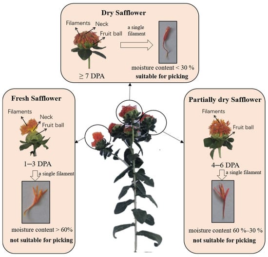
Figure 1.
Morphological diagram of safflower plant and filaments.

Table 1.
Macroscopic growth parameters of safflower.
2.2. Analysis of Mechanical Properties for Safflower
The necking of safflower is a structural feature formed by the overflow of silk clusters [26]. During filament harvesting, the separation of the filament from the fruit ball occurs precisely at this necking site [27]. Previous research has indicated that the average force required for filament separation by pulling is 15.03 N [28]. To explore a more optimal separation method, the shear force between a single filament and the fruit ball was measured using a texture analyzer (Streamline Process Co., Myrtle Beach, SC, USA) [29] (Figure 2a), yielding an average value of 8.75 N. Analysis combining these results with moisture content data of the filaments obtained using an electric thermostatic blast drying oven (Strayfield, UK) (Figure 2b) revealed that the binding force between the filament and the fruit ball is positively correlated with the filament moisture content. Furthermore, the shear force was significantly lower than the pulling force, demonstrating that shearing is a more effective pathway for achieving efficient filament separation. Shearing separation has been applied to some extent in safflower harvesting, where mechanical blades generate shearing force to cut the safflower filaments from their attached fruit balls. The same harvesting method has also been successfully applied to other crops, such as green Sichuan peppers [30], camellia flower [31], and dragon fruit [32]. However, it requires high positioning accuracy and has low efficiency, making it unsuitable for dry safflower harvesting. This study utilizes the shearing force generated by rotating flexible roller brushes to separate filaments from fruit balls, achieving high harvesting efficiency and enabling bulk collection.
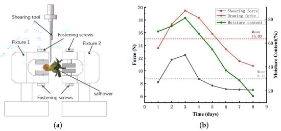
Figure 2.
Mechanical characterization: (a) Shearing principle; (b) Binding force vs. moisture content.
3. Dry Safflower Picking Mechanism and Integrated Machine Design
3.1. Shear Harvesting Mechanism Under Post Adjustment
The mechanical property tests conducted in this study revealed that, under identical picking mechanism parameters, the separation force required for shearing was consistently lower than that for pulling. This finding mechanically verifies the superiority of the shearing method during the harvesting process, as illustrated in Figure 3a. Given that the random spatial post of safflower fruit balls can prevent the shear force from acting directly on the filaments, a pose-adjustment mechanism was proposed. This mechanism is designed to reorient the fruit balls, ensuring the shear force acts directly on the filament roots (i.e., the necking zone), while simultaneously meeting the requirements for non-damaging clamping and stable conveyance [33]. Consequently, the design concept of a screw conveyor was innovatively introduced, leading to the development of a counter-rotating helical roller mechanism for pose adjustment. The pre-experiment compared the mutual position relationship between the brush filament and the flower filament under three posture adjustment conditions of θ < 90°, θ = 90°, and θ > 90°, and determined that the optimal condition is θ = 90°. Guided by the helical grooves of the adjusting rollers, the plant stem undergoes a controlled deflection. By appropriately setting the parameters of the helical adjusting rollers, the plant’s longitudinal axis is perpendicular to the rotational axis of the picking roller brush. This configuration presents the optimal harvesting post: the stem fully extends along the longitudinal direction of the flower passage, while the top of the fruit ball tangentially contacts the surface of the picking roller brush. In this optimal post, the shear force generated by the rotating picking brush acts precisely on the necking zone of the fruit ball. Through gentle contact and friction, the filaments undergo shear fracture at the necking, thereby transforming the traditional pull-off separation into a low-damage shear-based separation.
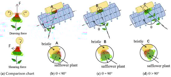
Figure 3.
Harvesting mechanism: A, B, and C are all partial enlargements.
3.2. Overall Structure and Technical Parameters
The mechanized harvesting device for dry safflower utilizes coordinated roller brushes to achieve plant post control and efficient, low-damage filament separation. The device primarily consists of crop lifters and feeding assembly, a pose-adjustment assembly, a picking assembly, a multi-directional adjustment assembly, and a frame, as shown in Figure 4. Crop lifters and feeding assembly located at the front of the harvester. A post adjustment assembly is placed at a parallel tilt inside the main frame, two counter-rotating spiral rollers brushes create a directional channel L. Picking roller brush is placed parallel to the post adjustment assembly, with a spacing of H. Multi-directional adjustment assembly distributed on the upper and lateral sides of the frame allow precise setting of roller brushes spacing, wheelbase and inclination. A fan, air duct and deflector plate are integrated to collect the detached safflower pneumatically. The key technical parameters of the dry safflower harvester are summarized in Table 2.
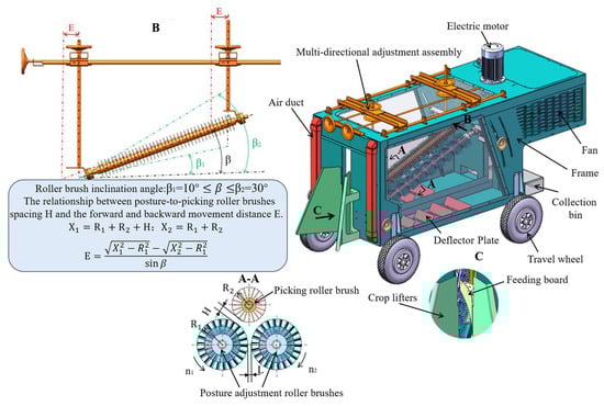
Figure 4.
Integrated Machine Structure: A is a partial sectional view, B is a partial front view, C is a partial view, L-gap between two pairs of roller brushes, H-post-to-picking roller brushes spacing.
Table 2.
Technical parameters of dry saffron harvesting machine.
4. Design of Key Components for the Roller-Brush Pose-Adjustment Dry Safflower Harvesting Device
4.1. Theoretical Analysis and Design of the Roller Brush
4.1.1. Study on the Force Characteristics of the Pose-Adjustment Roller Brush
During the operation of the pose-adjustment assembly, the implement moves forward continuously. Guided by the gatherer and feed plates, the safflower plant smoothly enters the working area of the pose-adjustment assembly. When the plant reaches the optimal position for pose adjustment, denoted as point A, as shown in Figure 5, it is subjected to several forces: a propulsion force F perpendicular to the helix angle, an impact force P perpendicular to the roller brush axis, and a frictional force f parallel to the roller brush axis [34]. The interaction of these forces induces a change in the spatial post of the safflower plant. The plant transitions from its initial vertical state relative to the ground to an oriented arrangement where it is perpendicular to the axis of the roller brushes, thereby successfully completing the pose-adjustment task.
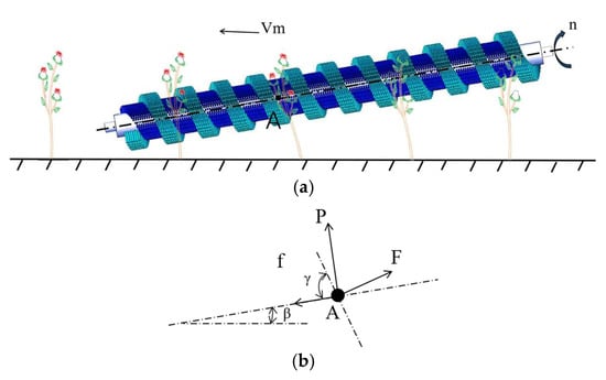
Figure 5.
Pose-adjustment analysis of the alignment assembly: (a)—Relative position between safflower plant and spiral roller brushes, (b)—Force analysis at point A on the safflower plant: β = inclination angle of the spiral roller brushes, γ = helix (spiral) angle of the spiral roller brushes, f = frictional force, P = impact force, F = propulsive (driving) force.
The safflower plant is subjected to a propulsive force F exerted by the long bristles, oriented perpendicular to the spiral trajectory. According to the work–energy theorem, the time-integral of F equals the change in kinetic energy along that direction:
where t = duration of the propulsive force acting on the safflower plant, (s); m = mass of the plant segment being pushed, (g); Δv = change in the plant’s velocity component along the direction of F, (m/s), defined as Δv = v2 − v1.
With the plant initially at rest in the relevant direction (v1 = 0), the velocity after interaction is v2 = vₘ cos (90° − γ + β).
The duration t (s) over which a safflower plant is acted upon by the propulsive force can be expressed as , where n = post adjustment roller brushes speed (r/min). The propulsive force F generated by the roller brushes on the safflower plant can be calculated,
Safflower plants are also subjected to impact force P, which is primarily related to the deformation of the short brush bristles. Since both the bristles and the filaments are elastic bodies, their contact can be regarded as an interaction between two elastic bodies. The Hertz theory [35] can be applied to determine the impact force P. However, the standard Hertz contact theory cannot fully capture the complex interactions between the brush bristles and the plant stem. Considering the material nonlinearity, viscoelasticity of the plant, and the complex deformation of the bristles, nonlinear correction coefficients and are introduced:
In the formula, E is the equivalent elastic modulus, measured in MPa. , , , , represents the elastic modulus and Poisson’s ratio of the bristles and safflower stems, respectively. R is the equivalent radius, measured in millimeters. , , are the radius of the bristles and the plant stem, respectively. is the amount of deformation of the bristles, in mm. The coefficient α1 is a nonlinear exponent primarily introduced to correct the magnitude of the contact stiffness, while α2 is a correction factor that adjusts the nonlinearity of the force–deformation relationship [36,37,38].
α1 is mainly used to correct the magnitude of the contact stiffness. It accounts for factors not included in the standard Hertz theory, such as material nonlinearity, surface roughness, and dynamic effects. α2 is used to adjust the nonlinearity of the force–deformation relationship. The standard Hertz theory assumes an exponent of 3/2. If the actual material exhibits stronger nonlinearity, then α2 > 0, resulting in a total exponent m > 3/2. Conversely, if the nonlinearity is weaker, α2 < 0.
The impact contact force between the bristles and filaments can be considered as the superposition of the local Hertz contact force FHertz and the bending force of the bristles Fbending. The bending force of the bristles is calculated using beam bending theory from material mechanics. The total force is expressed as Ftotal = FHertz + Fbending. By comparing this total force expression with the modified Hertz formula Ftotal = α·FHertz, the theoretical expression for α can be derived. This theoretical derivation is subsequently validated and refined using experimental data. By adjusting these two correction coefficients, the model can better fit experimental data, thereby more accurately describing the nonlinear contact behavior between the roller brush and the plant.
The frictional force on the stem is, , where is the coefficient of friction.
The force exerted by the spiral roller brushes on the plant is the vector resultant of the propulsive force F, the impact force P, and the frictional force f. Decomposing this resultant into components parallel and perpendicular to the brush axis, the component normal to the axis—denoted Fy—is the dominant contributor to plant post adjustment.
Equation (4) reveals that the post adjusting force Fy ranges from 0 to 12.73 N, and its magnitude is primarily governed by the spiral brush material, structural design, rotational speed, and the intrinsic properties of the safflower plant.
4.1.2. Structural Design and Parameter Determination of the Roller Brush
The key structural parameters of the roller brush were designed based on the macro-growth parameters of the ‘Yumin Thornless’ safflower cultivated in the drylands of Xinjiang and the principles of screw conveying [39,40], as illustrated in Figure 6. The major diameter of the helical blade (Dmax), minor diameter (Dmin), shaft diameter (d), sleeve diameter (D), and helical blade width (e) were determined as 125 mm, 85 mm, 25 mm, 60 mm, and 20 mm, respectively. The pitch of the helical roller brush plays a decisive role in the pose adjustment and conveying of the plant. An excessively small pitch prevents the fruit balls from entering the effective area of the brush bristles, resulting in a lack of axial separation. Conversely, an excessively large pitch leads to an overly large helix angle of the blade, causing the axial component of the force acting on the flower stem to be less than its elastic recovery force, thereby causing conveying failure. Based on this analysis, and adhering to the design criteria of “pitch > maximum fruit ball diameter” and “axial force > radial force”, the pitch (s) was determined to be 120 mm, and the blade thickness (h) was set to 60 mm [41].
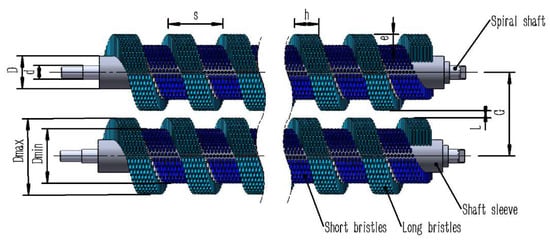
Figure 6.
Dimensioned schematic of spiral roller brushes.
The center distance (G), defined as the distance between the axes of the two helical roller brushes, directly influences the plant-brush contact state and conveying efficiency. A center distance that is too small can cause plant jamming and blockage, while one that is too large leads to a loss of contact between the brush bristles and the plant, resulting in a failure of conveyance. For a given pitch, the center distance is negatively correlated with the plant-brush contact area; meaning a smaller center distance yields superior pose-adjustment and conveying performance. The minimum center distance (the theoretical minimum) occurs when the gap between the long brush bristles is 0 mm and the gap between the short brush bristles is 40 mm. At this setting, the spacing of the short brush bristles and the elasticity of the brush bristles allow the safflower plant to pass through smoothly while maintaining favorable force conditions. Consequently, the gap between long brush bristles L was set to 0 mm, and the center distance G was determined to be 125 mm.
To facilitate manufacturing, the parameters of the picking roller brush shaft were kept consistent with those of the helical roller brush shaft: the sleeve diameter (D) is 60 mm, and the shaft diameter (d) is 25 mm. The brush bristle length was determined to be 20 mm based on the requirement for sufficient contact with the filaments, ensuring an effective picking action. The working area of the obliquely mounted picking roller brush should fully cover the spatial distribution area of the safflower fruit balls. Its axial length depends not only on the vertical distribution range of the fruit balls but is also closely related to the installation angle of the roller brush and the inclination angle of the plant. Under the multi-directional adjustment assembly, the position of the roller brush rear end inside the main frame is changed by rotating the handwheel, thereby setting and maintaining the brush angle β. The spatial positional relationship is illustrated in Figure 7.
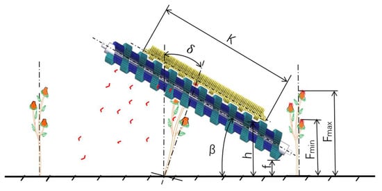
Figure 7.
Schematic of the positional relationship between the roller brushes and the safflower plant: β = roller brushes inclination angle, f = vertical distance from spiral roller brushes to ground, K = picking roller brush length, h = vertical distance from picking roller brush to ground, F = safflower plant height, δ = plant inclination angle.
Based on the minimum height of the lowest fruit ball being 310 mm, the height (h) of the picking roller brush from the ground was set to 300 mm. Considering factors such as ground unevenness, a certain distance must be maintained between the pose-adjustment roller brush and the ground; a value of f = 100 mm was selected. Referring to related domestic and international machinery, the installation inclination angle (β) of the pose-adjustment roller brush is generally no less than 10°. Assuming the pose-adjustment roller brush operates with optimal performance at this angle, causing the axis of the safflower fruit ball to be perpendicular to the axis of the pose-adjustment roller brush, the plant inclination angle (δ) equals the installation angle (β).
Based on Equation (5), the length range of the picking roller brush was calculated to be 346.41 mm to 1134.25 mm. To reduce the spatial dimensions of the picking mechanism and facilitate machining, a length (K) of 800 mm was selected for the picking roller brush. As the helical roller brush serves as the subsequent conveying unit, its length must be greater than that of the picking roller brush to ensure functional continuity. Consequently, the length of the helical roller brush was determined to be 1200 mm.
4.2. Kinematic Characteristics Study of the Roller Brushes
4.2.1. Motion Trajectory Analysis of the Roller Brushes
To ensure continuous contact and uniform force application between the safflower fruit balls and the picking roller brush under the action of the pose-adjustment mechanism, the oblique installation angles of the helical pose-adjustment roller brushes and the picking roller brush were set to be identical. This configuration simplifies the structure and avoids localized excessive wear. During the operation of the harvesting device, both the helical pose-adjustment roller brushes and the picking roller brush not only rotate about their own axes but also move forward with the device. The velocity of any point on a roller brush is the vector sum, within a plane, of its circumferential velocity (Vp) around the brush axis and the forward velocity (Vm) of the harvesting device [42]. The resulting motion trajectory is illustrated in Figure 8.
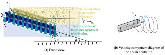
Figure 8.
Roller brushes motion trajectory: (a)—Front view; (b)—Top view.
Figure 8 shows the left-side pose-adjustment roller brush and the picking roller brush, rotating clockwise. Point A is an arbitrary point on the circumference at the outer end of a roller brush. Assuming at time t = 0, point A rotates to a position horizontal with the axis center within the cross-section, the motion trajectory of point A is given by:
where vₘ is the forward speed of the harvester (m/s), R is the roller radius (m), ω is the angular velocity of the roller (rad/s). Differentiating Equation (6) with respect to time t gives the velocity components of point A:
where , , and are the velocity components of point A along the x-, y-, and z-axes, respectively (m/s), and v0 is the circumferential line speed at the outer edge of the roller brush, v0 = ω R. The absolute velocity v of point A is then the magnitude of the absolute velocity v of point A can be expressed as:
The magnitude of the absolute velocity v at the outer end of the roller brush significantly influences the pose-adjustment effect on the safflower plant, which further determines the filament picking rate and damage rate. This process is primarily related to three key parameters: the forward speed of the device, the rotational speed of the roller brushes, and their inclination angle. Optimizing the performance of the harvesting device by rationally configuring these parameters is essential for achieving the best picking results.
4.2.2. Analysis of the Influence of Helical Roller Brush Motion Parameters on Pose-Adjustment Effect
During the operation of the harvesting device, the safflower plant is subjected to impact and propulsion forces from the pose-adjustment roller brushes, causing the plant to bend to a certain extent and thereby adjusting the spatial post of the fruit balls. This post adjustment mechanism is based on the elastic deformation of the plant. The bending angle is closely related to the rotational speed of the roller brushes and the forward speed of the machine. Specifically, the angle α between the axis of the safflower fruit ball and the horizontal plane is essentially consistent with the angle between the absolute velocity vector of the roller brush and the machine’s forward velocity vector. This angle can be determined by the cosine theorem [43].
Let the ratio of the brush-tip peripheral speed to the machine forward speed be defined as the dimensionless coefficient, k = v0/. Equation (8) can then be rewritten in terms of k as
Substituting Equation (10) and = R ω into Equation (9) yields, so that Equation (9) can be expressed as
When the bristle reaches the horizontal position and just touched the safflower fruit ball (t = 0), the picking engagement angle attains its maximum value.
Under the guidance of the post adjusting assembly, the safflower fruit ball axis is brought perpendicular to the picking-brush axis (γ = 90°). In this configuration, the bristles make direct contact with the safflower constriction (neck) region, applying a shear force that minimizes the detachment force required to separate the safflower from the fruit ball. Preliminary experiments show that effective contact between the safflower and the bristles—and hence satisfactory picking—occurs when γ lies within 81° < γ < 99°. Because α + β = 180° − γ, the fruit ball reaches an optimal picking post when 81° < α + β < 99°, which satisfies the design requirements.
Figure 9 presents the K–α curves obtained for β = 15°, 20°, and 25° within the interval K ∈ [1, 20]. At any fixed K, α decreases monotonically with increasing β. When β = 0° the brush is horizontal and contacts only a narrow height band of the plants, so it cannot accommodate capitula at different elevations, severely limiting adaptability. Conversely, at β = 90° the brush is vertical; the accompanying impact and pushing forces markedly increase plant deflection and lodging risk, which is detrimental to efficient and safe filament harvest. The curves indicate that as K increases, the sum α + β asymptotically approaches 90°. Preliminary experiments comparing bristle–filament contact at various orientations established that the bristles simultaneously engage the base of every filament on an individual capitulum only when 81° < α + β < 99°; this interval therefore defines the operative picking pose that satisfies the adjustment requirement. Specifically: If K < 5.99, α + β < 81°, the fruit ball cannot be re-oriented into the required picking post, resulting in a significant reduction in picking rate. When K ≥ 5.99, α + β enters the acceptable range, and further increases in K progressively fruit ball the picking post, thereby improving harvest quality. However, K should not be increased indefinitely. Excessive rotational speed elevates the absolute picking velocity, which in turn raises the likelihood of damage rate and may even shear entire fruit ball from the stem. Therefore, to balance high recovery with minimal mechanical damage, the design value is set to K = 6. Because larger β values increase the stem inclination and hence the risk of plant damage, β is fixed at 15°.
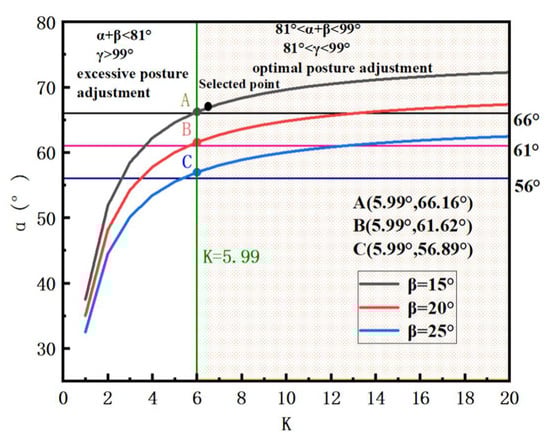
Figure 9.
K–α function plot.
The rotational speed of the post adjusting spiral roller brushes should therefore be optimized on the basis of its re-orientation performance, and the optimal speed is obtained by jointly considering the machine forward speed Vₘ and the speed ratio K.
The relationship between the rotational speed of the spiral roller brushes and its peripheral (tip) linear speed is
For flexible picking elements, the dimensionless factor K is generally accepted to lie in the range 5.0–5.2 [44]. Bench tests showed that the critical rotational speed above which dry safflower begin to suffer mechanical damage is 600 r/min. Setting K = 5 and roller diameter D = 100 mm, Equation (14) yields a maximum allowable machine forward speed Vₘ = 0.6 m/s. Reducing Vₘ lengthens the interaction time between the spiral roller brushes and the plant, allowing the post-correcting forces to accumulate and increasing the bristle–safflower contact duration; both effects raise the picking rate. However, excessively low forward speeds compromise operational efficiency. Balancing picking rate and damage rate, the working forward speed was fixed at Vₘ = 0.4 m/s. For K = 6, Vₘ = 0.4 m/s and D = 140 mm, Equation (14) gives the required rotational speed of the post adjusting spiral roller brushes as n = 327.57 r/min. Hence, the final operating parameters are: machine forward speed: 0.4 m/s; spiral roller brushes speed: 327.57 r/min; roller inclination angle: 15°.
5. Experiments
5.1. Experimental Materials and Equipment
The experiments presented in this paper were conducted in May 2025 at the Key Laboratory of the College of Mechanical and Electrical Engineering, Shihezi University, Shihezi City. The test material was the ‘Yumin Thornless’ safflower cultivated under dryland conditions at the experimental station of Shihezi University. The test equipment and tools included: a performance test platform for the roller-brush pose-adjustment dry safflower harvesting device, an angle measuring instrument (accuracy 0.01°), an electronic balance (range 300 g, accuracy 0.001 g), a digital vernier caliper (accuracy 0.02 mm), a sieve mesh (20-mesh), and a standard calculator. The performance test platform for the roller-brush pose-adjustment dry safflower harvesting device is shown in Figure 10.
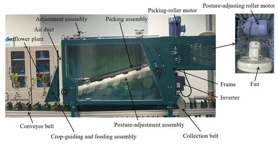
Figure 10.
Performance test platform of the roller-brush pose-adjustment dry safflower harvesting device.
5.2. Validation Test for Pose-Adjustment Effect
To validate the effectiveness of the previously determined pose-adjustment parameter combination under actual operating conditions, a validation test was designed and implemented. Twenty dry safflower plants were selected for the test. Under constant temperature and humidity conditions, the variation in the plant movement angle was synchronously captured using high-speed photography (1000 fps), as shown in Figure 11. The primary metric was the angle θ between the fruit ball axis and the brush roller axis after adjustment, at this time, the theoretical post angle is 98°. Measured θ ranged from 91.97° to 98.33°, the average is 95.36°, fully within the target interval of 81–99°. The standard deviation was 2.29°, and the root-mean-square error (RMSE) was 3.42°, providing favorable experimental conditions for the subsequent picking tests.
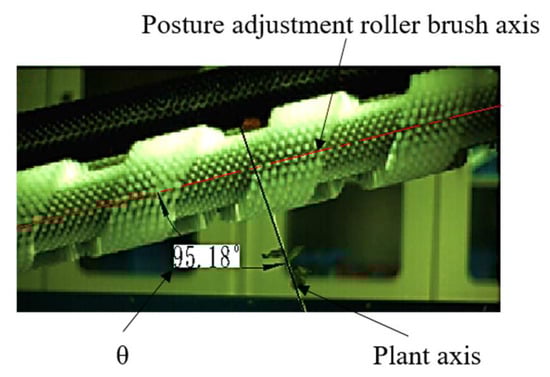
Figure 11.
Experimental diagram.
5.3. Picking Test Methods and Evaluation Indices
Tests were conducted to evaluate the picking performance of the roller-brush pose-adjustment dry safflower harvesting device. The rotational speed of the picking roller brush (n), the spacing between the picking roller brush and the helical pose-adjustment roller brush (x), and the diameter of the picking roller brush bristles (d) were selected as test factors. The picking rate, damage rate, and fruit injury rate were used as evaluation indices. The parameter optimization ranges were determined based on preliminary tests: picking roller brush speed n = 400–600 r/min, roller brush spacing x = 0–20 mm, and brush bristle diameter d = 0.1–0.3 mm. A Box–Behnken experimental design was employed to seek the optimal parameter combination. The formulas for calculating the picking rate Y1 (%); damage rate Y2 (%); fruit injury rate Y3 (%) are as follows:
where M0 = mass of detached dry safflower within the sampling zone, g; M1 = mass of residual (undetached) dry safflower within the same zone, g; T0 = mass of broken safflower that pass through the 20-mesh sieve, g; T1 = mass of intact safflower retained on the 20-mesh sieve, g; N0 = total number of fruit in the sampling zone, pieces; N1 = number of mechanically damaged fruit, pieces; N2 = number of fruit that detached and dropped to the ground during processing, pieces.
5.4. Bench Test for Picking Performance
5.4.1. Box–Behnken Experimental Design
Based on the parameter ranges determined from theoretical analysis, a Box–Behnken experimental design was implemented using Design-Expert 13 software to investigate the effects of different combinations of the influencing factors on the response indices. The levels of the experimental factors are presented in Table 3. Each test group was repeated 10 times, and the average value, after removing outliers, was taken as the test result. The experimental design and results are shown in Table 4.
Table 3.
Factor-level design for the experiment.
Table 4.
Experimental scheme and results.
5.4.2. Effects of Factors on the Picking Rate, Damage Rate, and Fruit Injury Rate
Regression fitting and analysis of variance (ANOVA) were performed on the experimental results. The interaction terms x1x3 for Y1, x1x3 for Y2, and x1x2 for Y3 were found to be non-significant and were therefore excluded from the final models. The final ANOVA results are summarized in Table 5.
Table 5.
Analysis of variance for the effects of influencing factors on the picking rate, damage rate, and fruit injury rate.
The regression models were statistically significant, with all p-values less than 0.05 and non-significant lack-of-fit terms, demonstrating a good overall fit to the experimental data. The adjusted coefficients of determination (R2) were 0.9874, 0.9860, and 0.9778, respectively. Being close to 1, these values indicate that the models explain only 1.26%, 1.4%, and 2.22% of the total variation, respectively, demonstrating a good model fit and high predictive accuracy. Under these conditions, the regression equations relating the influencing factors to the response indices for the picking rate, damage rate, and fruit injury rate were derived as follows:
The interaction effects of the influencing factors on the picking rate are shown in Figure 12. When the bristle diameter was 0.2 mm, the picking rate initially increased and then decreased with the increase in roller brush speed, reaching a peak value at 320 r/min. This is primarily because the increased speed enhances the shear stress exerted by the brush bristles; however, beyond a critical value (320 r/min), the excessively short contact time diminishes the effective shearing action. Concurrently, the picking rate showed insignificant variation when the spacing was less than 3 mm but decreased continuously when the spacing exceeded 3 mm. This occurs because the increased spacing directly reduces the effective contact area between the brush bristles and the filaments. Response surface analysis indicated that, under these conditions, the roller brush speed was a more significant influencing factor than the spacing. When the roller brush speed was fixed at 300 r/min, the picking rate decreased with increasing spacing but increased with increasing bristle diameter. The latter effect is attributed to the enhanced separation efficiency resulting from the increased stiffness of the brush bristles. In this scenario, the spacing became a more significant factor than the bristle diameter.
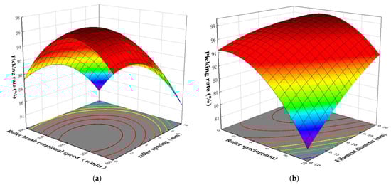
Figure 12.
Response-surface plots for picking rate: (a)—Effects of roller speed and roller spacing on picking rate; (b)—Effects of roller spacing and bristle diameter on picking rate. The color gradient follows a rainbow spectrum, ranging from violet to red, where violet indicates the lowest picking ratio and red indicates the highest. The contour lines in the plot illustrate the distribution of the picking rates under different conditions, assisting in identifying the optimal harvesting conditions.
The interaction effects of the influencing factors on the damage rate are shown in Figure 13. With a bristle diameter of 0.2 mm, the damage rate changed gradually at speeds below 275 r/min but increased monotonically beyond this value. This is due to the load applied by the brush bristles remaining within the elastic deformation range of the filaments at lower speeds, causing minimal damage, whereas the instantaneous high impact energy generated at higher speeds exacerbates material failure. Simultaneously, the damage rate continuously decreased as the spacing increased, because the larger spacing alleviates stress concentration, leading to a more uniform load distribution. Response surface analysis revealed that the spacing was a more significant influencing factor than the roller brush speed. When the speed was fixed at 300 r/min, the damage rate increased with the bristle diameter, as the increased stiffness of the brush bristles directly amplifies the mechanical load applied to the filaments. Under these conditions, the bristle diameter became a more significant factor than the spacing.
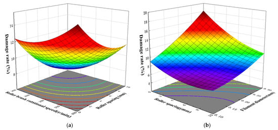
Figure 13.
Response-surface plots for damage rate: (a)—Effects of roller speed and roller spacing on damage rate; (b)—Effects of roller spacing and bristle diameter on damage rate. The color gradient follows a rainbow spectrum, ranging from violet to red, where violet indicates the lowest damage ratio and red indicates the highest. The contour lines on the base plane provide a top-down view of the damage rate distribution across different conditions.
The interaction effects of the influencing factors on the fruit injury rate are shown in Figure 14. With a spacing of 5 mm, the fruit injury rate increased continuously with the roller brush speed, mainly because the increased instantaneous impact frequency and cumulative kinetic energy cause the mechanical stress on the fruit balls to exceed their damage threshold. Meanwhile, the fruit injury rate first decreased and then stabilized as the bristle diameter increased. At smaller bristle diameters (0.1–0.2 mm), the lower stiffness of the brush bristles resulted in contact stress below the damage threshold, yielding a lower fruit injury rate. When the bristle diameter exceeded 0.2 mm, the stiffness increased significantly, but the change in the fruit injury rate tended to stabilize. Response surface analysis indicated that the roller brush speed was a more significant influencing factor than the bristle diameter. When the speed was fixed at 300 r/min, the fruit injury rate decreased with increasing spacing, as the wider passage reduced the collision probability and stress concentration, and increased with increasing bristle diameter due to the enhanced brush bristle stiffness. In this case, the bristle diameter became a more significant factor than the spacing.
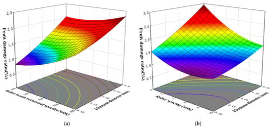
Figure 14.
Response-surface plots for fruit injury rate: (a)—Effects of roller speed and bristle diameter on fruit injury rate; (b)—Effects of roller spacing and bristle diameter on fruit injury rate. The color gradient follows a rainbow spectrum, ranging from violet to red, where violet indicates the lowest fruit injury ratio and red indicates the highest. The contour lines on the base of the plot provide a top-down view of the distribution of the fruit injury rates under various conditions.
5.4.3. Parameter Optimization
To optimize the parameter combination for the best picking performance of the dry safflower harvesting device, with the objectives of maximizing the picking rate and minimizing the damage rate and fruit injury rate, a constrained optimization was performed on the aforementioned three regression models. The objective function and constraints are as follows:
Using the optimization function in Design-Expert 13 software, the objective function was optimized, yielding the optimal parameter combination: roller brush speed = 282.5 r/min, spacing = 3.7 mm, brush bristle diameter = 0.1 mm. Under this combination, the model predicts a picking rate of 93.26%, a damage rate of 6.78%, and a fruit injury rate of 1.13%.
5.5. Validation Tests
According to the relevant requirements of T/SHZSAQS 00064-2022 “Technical Code for Mechanized Harvesting of Safflower” [45], a picking rate above 80% and a fruit ball drop rate below 5% are sufficient to meet the harvest requirements. Based on the optimization results, validation tests with 5 replicates were conducted using a roller brush speed of 282.5 r/min, a spacing of 3.7 mm, and a brush bristle diameter of 0.1 mm. The average values of the picking rate, damage rate, and injured fruit rate for dry safflower were 92.4%, 7.1% and 1.2%, respectively, with standard deviations of 5.42%, 0.51%, and 0.08%. The relative errors compared to simulated predictions were 2.08, 0.63, and 0.18 percentage points, respectively, indicating reliable prediction results. Compared to existing dry safflower picking devices, the picking efficiency increased by 11.11 percentage points, and the picking rate improved by 2.21 percentage points. Additionally, accurate measurement of the damage rate was achieved, remaining below 10%, while damage to fruit balls and stems was controlled at a low level. This advancement promotes the mechanical harvesting of dry safflower into a new phase.
6. Conclusions
- (1)
- The ‘Yumin Thornless’ safflower is a terminal-bearing, multi-branched crop. Mechanical tests showed that the average shear separation force (8.2 N) is significantly lower than the pulling force (15.03 N). The shear fracture threshold for a single filament on the seventh day after flowering was 2.9 N, providing a theoretical basis for low-damage shear harvesting.
- (2)
- This study proposes a “pose-adjustment and shearing” mechanism: the counter-rotating helical pose-adjustment rollers deflect the randomly posed fruit balls until the plant stem is orthogonal to the roller brush axis, enabling the shear force to act precisely on the necking zone. Based on this, a coordinated roller-brush harvesting device was designed, which completes the processes of plant guiding → pose adjustment → picking → pneumatic collection in a single pass, providing a solution for continuous, low-damage harvesting of dry safflower.
- (3)
- The key components of the dry safflower harvesting device were analyzed and designed. Mechanical analysis indicated that at the optimal pose-adjustment point A, the plant is subjected to a resultant force of 0–14.33 N to achieve post adjustment from vertical to orthogonal to the roller brush axis; based on this, the structural parameters of the roller brush were selected. The kinematic model revealed that the post angle α and the velocity ratio K determine the adjustment effect. Considering the limiting speed of 600 r/min and efficiency requirements, the final parameters were determined as forward speed = 0.4 m/s, helical roller brush speed = 330 r/min, and inclination angle = 15°.
- (4)
- The pose-adjustment performance validation test, based on theoretical analysis results, showed that the measured average angle between the plant stem and the roller brush axis was 95.27°, falling within the target range of 81–99°. The adjustment accuracy meets the requirements for subsequent picking. Bench tests employing a Box–Behnken design identified the optimal parameter combination for picking as roller brush speed = 282.5 r/min, spacing = 3.7 mm, brush diameter = 0.1 mm. Validation confirmed average values of 91.18% for picking rate, 6.18% for damage rate, and 0.95% for fruit injury rate. The close agreement between measured and predicted values for all indices indicates that the model’s accuracy meets the requirements for optimizing the picking mechanism’s parameters and satisfies the technical code for safflower harvesting.
Author Contributions
Conceptualization, C.M. and H.Z.; methodology, C.M.; validation, G.L., B.H. and Y.G. (Yangyang Guo); formal analysis, Y.G. (Yun Ge); investigation, C.M.; resources, H.Z.; data curation, G.L.; writing—original draft preparation, C.M.; writing—review and editing, H.Z.; visualization, H.Z.; supervision, Y.G. (Yun Ge); project administration, H.Z.; funding acquisition, H.Z. All authors have read and agreed to the published version of the manuscript.
Funding
This research was funded by the National Natural Science Foundation of China (32260430).
Data Availability Statement
Data are contained within the article.
Conflicts of Interest
The authors declare no conflicts of interest.
References
- Kassa, B.A.; Mekbib, F.; Assefa, K. Effects of plant hormones and genotypes on anther culture response of safflower (Carthamus tinctorius L.). Sci. Afr. 2024, 26, e02367. [Google Scholar] [CrossRef]
- Lv, X.; Xin, X.; Liang, S.; Adilai, A. Exploration of dyeing process and cultural product development of Xinjiang safflower. West. Leather 2024, 46, 71–74. [Google Scholar]
- Federica, Z.; Angelini, L.G.; Sara, B.; Foschi, L.; Clemente, C.; Ferioli, F.; Vecchi, A.; Rossi, A.; Monti, A.; Tavarini, S. Safflower (Carthamus tinctorius L.) a winter multipurpose oilseed crop for the Mediterranean region: Lesson learnt from on-farm trials. Ind. Crops Prod. 2022, 184, 115042. [Google Scholar]
- Abbaspour-Fard, H.M.; Yousefzadeh, H.; Azhari, A.; Ebrahimi-Nik, M.A.; Moghaddam, M.H. Ergonomic evaluation of conventional saffron harvesting versus using a trolley. Saffron Agron. Technol. 2018, 6, 253–267. [Google Scholar]
- Azimi, S.; Chegini, G.; Kianmehr, M.H. Design and manufacture of safflower petal harvester machine. Mech. Ind. 2012, 13, 301–305. [Google Scholar] [CrossRef]
- Ge, Y.; Zhang, L.; Han, D.; Cao, S.; Wang, M.; Lu, Y.; Ying, Y. Current situation and development trend of mechanical harvesting of safflower filaments. J. Agric. Mech. Res. 2014, 36, 265–268. [Google Scholar]
- McGuire, P.E.; Damania, A.B.; Qualset, C.O. Safflower in California. The Paulden F. Knowles Personal History of Plant Exploration and Research on Evolution, Genetics, and Breeding; University of California: Davis, CA, USA, 2012. [Google Scholar]
- Rahman, T.U.; Faraz, A.; Nawaz, T.; Saud, S.; Fahad, S.; Harrison, M.T. Towards Sustainable Solutions: Climate Change and Food Security in a Globalized World. Food Energy Secur. 2025, 14, e70126. [Google Scholar] [CrossRef]
- Rajvanshi, A.K. Development of Safflower Petal Collector. Nimbkar Agric. Res. Inst. 2005, 19, 6–10. [Google Scholar]
- Bertetto, A.M.; Ricciu, R.; Badas, M. A mechanical saffron flower harvesting system. Meccanica 2014, 49, 2785–2796. [Google Scholar] [CrossRef]
- Ichiura, S.; Yoshihiro, H.; Sato, K.; Onodera, R.; Katahira, M. Safflower Production Management ECOSYSTEM with AI Harvester; American Society of Agricultural and Biological Engineers: St. Joseph, MI, USA, 2020. [Google Scholar]
- Chen, B.; Yao, Q.; Ding, F.; Li, K.; Ma, B. Design and optimization of a negative-pressure rotary-cutting safflower filament harvesting device. Sci. Rep. 2025, 15, 9693. [Google Scholar] [CrossRef]
- Zhou, K.; Yan, D.; Li, Y.; Hou, J.; Zhang, Z.; Wu, Y.; Li, Y.; Jia, C.; Liang, X.; Li, X. A Brush Roller-Type Safflower Harvesting Machine and Its Usage Method. CN116616042A, 22 August 2023. [Google Scholar]
- Xu, Y.; Huang, B.; Wang, X.; Chen, J.; Cui, C.; Liu, Z.; Zhao, Y. A Highly Efficient Safflower Picking Platform. CN219373139U, 21 July 2023. [Google Scholar]
- Li, Y.; Yan, D.; Tan, C.; Shi, H.; Zhou, K.; Zhang, Z.; Jia, C. A Rubbing Type Safflower Flower Picking Machine and Its Picking Method. CN116897692A, 25 August 2023. [Google Scholar]
- He, Y. A Dry Safflower Picking Machine. CN113439540A, 28 September 2021. [Google Scholar]
- Zhao, F. A Synchronous-Clamping Brush-Roller Safflower Picking Device. CN220712110U, 26 August 2023. [Google Scholar]
- Uljayev, E.; Ravutov, S.T.; Ubaydullayev, U.M. Remote control device to control the contact uniformity of the brush strippers on the spindle’s surface of the cotton picking apparatus. IOP Conf. Ser. Earth Environ. Sci. 2020, 614, 012139. [Google Scholar] [CrossRef]
- Yan, D. Design and Experiment of a Brush-Roller Safflower Harvesting Device. Master’s Thesis, Shandong Agricultural University, Taian, China, 2024. [Google Scholar]
- Sun, C.; Ge, Y.; Zhang, H.; Zeng, H.; Zhang, L. Design and experiment of the vertical brush-roller picking device for dry-safflower harvesters. Trans. Chin. Soc. Agric. Eng. 2024, 40, 203–211. [Google Scholar]
- Xin, X. Design and Research of a Collection Device for Dried Safflower Harvesting Machine. Master’s Thesis, Shihezi University, Shihezi, China, 2024. [Google Scholar]
- Zhang, L.; Zeng, H.; Ge, Y.; He, B.; Ma, C.; Guo, Y. Design and experiment of an inclined brush-roller picking device for dried safflower. Trans. Chin. Soc. Agric. Eng. 2025, 41, 40–50. [Google Scholar]
- Dong, J.; Ge, Y.; Chu, S.; Zheng, Y.; Zeng, H.; Guo, D. Design and kinematic analysis of a feeding and spacing mechanism for safflower fruit balls. J. Shihezi Univ. 2024, 42, 22–29. [Google Scholar]
- Wang, X.; Xu, Y.; Zhou, J.; Chen, J. Recognition of safflower for picking in complex environments based on improved YOLOv7. Trans. Chin. Soc. Agric. Eng. 2023, 39, 169–176. [Google Scholar]
- Qiu, Z.; Guo, H.; Gao, G.; Wu, T.; Chen, H. Design and experiment of an end-effector for a safflower picking robot. J. Chin. Agric. Mech. 2025, 46, 271–276. [Google Scholar]
- Zhang, Z.; Zeng, C.; Xing, Z.; Xu, P.; Guo, Q.; Shi, R.; Wang, Y. Discrete element modeling and parameter calibration of safflower biomechanical properties. Int. J. Agric. Biol. Eng. 2024, 17, 37–46. [Google Scholar] [CrossRef]
- Chen, Y. Design and Research of Roller-Type Safflower Picking Performance Test Device. Master’s Thesis, Shihezi University, Shihezi, China, 2017. [Google Scholar]
- Sun, W.; Cao, W.; Gu, L.; Liu, J.; Wang, S. Design and experiment of comb-clamp picking mechanism based on mechanical properties of safflower. J. Agric. Mech. Res. 2018, 40, 46–51. [Google Scholar]
- Owen, J.P.; Cleary, W.P. Screw conveyor performance: Comparison of discrete element modelling with laboratory experiments. Prog. Comput. Fluid Dyn. 2010, 10, 327–333. [Google Scholar] [CrossRef]
- Yang, L.; Zhang, Y.; He, Z.; Li, S.; Pu, Y.; Chen, W.; Yang, S.; Yang, M. Design and experiment of the rotating shear picking device for green Sichuan peppers. Trans. Chin. Soc. Agric. Eng. 2024, 40, 72–83. [Google Scholar]
- Lyu, H.; Li, L.; Zhao, Q.; Wu, Z.; Guo, X. Design and experiment of a shear-type picking end-effector for camellia flowers. J. Agric. Mech. Res. 2024, 46, 134–139+144. [Google Scholar]
- Chen, Q.; Xiao, M.; Luo, C.; Gao, J.; Ou, Y.; Zeng, C.; Li, W.; Zhou, X. Design of elliptical claw shear-type picking end-effector for dragon fruit. J. Agric. Sci. Technol. 2025, 27, 113–121. [Google Scholar]
- Charles, K. Berkeley Physics Course, Vol. 1: Mechanics; China Machine Press: Beijing, China, 2015. [Google Scholar]
- Johnson, K.L. Contact Mechanics; Higher Education Press: Beijing, China, 1992. [Google Scholar]
- Johnson, K.L. Contact Mechanics; Cambridge University Press: Cambridge, UK, 1998. [Google Scholar]
- Feng, Z.; Wu, J.; Sun, H.; Li, F. Measurement and analysis of apple static compression contact stress distribution characteristics. Mod. Food Sci. Technol. 2014, 30, 76–81. [Google Scholar]
- Ji, W.; Tang, C.; Xu, B.; He, G. Contact force modeling and variable damping impedance control of apple harvesting robot. Comput. Electron. Agric. 2022, 198, 107026. [Google Scholar] [CrossRef]
- Liu, J.; Yang, K. Vibration-impact composite dynamics modeling of grape cluster systems for non-destructive harvesting and transport. J. Jiangsu Univ. 2022, 43, 178–183. [Google Scholar]
- Minglani, D.; Sharma, A.; Pandey, H.; Dayal, R.; Joshi, J.B. Analysis of flow behavior of size distributed spherical particles in screw feeder. Powder Technol. 2021, 382, 1–22. [Google Scholar] [CrossRef]
- Zhao, L. Design and Experimental Study on a Spiral Comb-Brush Apple Harvesting Machine. Master’s Thesis, Northwest A&F University, Xianyang, China, 2022. [Google Scholar]
- Jia, C. Research on Parameter Design and Optimization Method of Screw Conveyor. Master’s Thesis, Taiyuan University of Technology, Taiyuan, China, 2015. [Google Scholar]
- Liu, L.; Wu, T.; Kong, F.; Sun, Y.; Chen, C. Optimal design and experiment of picking mechanism for brush-roller castor harvester. Trans. Chin. Soc. Agric. Eng. 2021, 37, 19–29. [Google Scholar]
- Wang, L.; Zhang, H.; Liu, Q. Experiment on harvesting performance of rubber-finger drum cotton picking head. Trans. Chin. Soc. Agric. Eng. 2016, 32, 35–41. [Google Scholar]
- Chinese Academy of Agricultural Mechanization Sciences. Agricultural Machinery Design Handbook; China Machine Press: Beijing, China, 1990; Volume 2. [Google Scholar]
- T/SHZSAQS 00064-2022; Technical Regulations for Mechanized Harvesting of Safflower. National Library of Standards: Beijing, China, 2022. Available online: https://www.ndls.org.cn/standard/detail/f9880ccff8e9f9b72c2af94cd1f769df (accessed on 24 April 2022).


Disclaimer/Publisher’s Note: The statements, opinions and data contained in all publications are solely those of the individual author(s) and contributor(s) and not of MDPI and/or the editor(s). MDPI and/or the editor(s) disclaim responsibility for any injury to people or property resulting from any ideas, methods, instructions or products referred to in the content. |
© 2025 by the authors. Licensee MDPI, Basel, Switzerland. This article is an open access article distributed under the terms and conditions of the Creative Commons Attribution (CC BY) license (https://creativecommons.org/licenses/by/4.0/).