Abstract
In comparison to internal combustion engines, which usually have low frequency, broadband excitations, in electric vehicles, tonal excitations from the electric drivetrain are noticeable and disturbing. As the acoustic and structural dynamic behavior, often referred to as noise, vibration, and harshness (NVH), strongly influences customers’ quality perceptions, optimizing it is a key challenge in development. This study investigates the influence of static rotor–stator eccentricity on the NVH behavior of an electric drivetrain using a transient elastic multibody simulation (eMBS) model incorporating non-linear gear meshing, bearing contact, and electromagnetic forces. The analysis identifies the 36th order excitation of the electric machine as the dominant source, leading to a maximum total acceleration level of 152 dB. Two specific excitation directions were found to reduce this amplitude most effectively. However, varying the amount of static eccentricity in these directions resulted in only minor vibration reductions (<1.5 dB). The findings indicate that the symmetric mode shapes of the cylindrical housing govern the response, indicating that addressing the excitability of housing modes by developing asymmetric housing designs could offer a more effective approach for NVH optimizations of electric drivetrains.
1. Introduction
In the highly competitive automotive industry, subjective purchase decisions of the customer, such as driving comfort, become highly relevant for the manufacturer. In electrified drivetrains, the tonal excitation of the electric machine is particularly noticeable in vehicle acoustics. Since tonal noise is perceived as unpleasant by the customers of electric vehicles, optimizing the NVH characteristics of electric drivetrains is a major objective during product development [1]. In order to meet requirements such as cost-efficiency and reduced time to market of the product, model-based optimization approaches are commonly used to improve the NVH characteristics of electric drivetrains based on virtual prototypes [2].
Simulation approaches such as the finite element method (FEM) and the elastic multibody simulation (eMBS) have become established for analyzing and optimizing the NVH behavior of drivetrains [2]. While analytical machine models are still in use to calculate the currents and forces of the electrical machine, coupling the excitations with finite element (FE) models is necessary to determine the system’s structural dynamic response [3,4]. The latter can then be used to calculate the emitted sound pressure level, which mainly influences the customer’s purchase decision [4]. Although the FEM is widely used during development processes to evaluate individual components, mainly in frequency domains, the eMBS modeling approach is needed to simulate the non-linear transient NVH behavior of a drivetrain with sufficient computational efficiency [2]. Enabling the simulation of non-linear effects is crucial, especially for electrified drivetrains, since the non-linear electromagnetic forces, which are affected by the eccentricity, interact with the non-linear structural dynamic properties of the drivetrain, e.g., the air gap of the bearings [5]. This interaction can be modeled using a multi-slice modeling approach within the eMBS domain, where electromagnetic forces are applied both on the elastic stator teeth and the elastic rotor through different slices in axial direction [6]. This ensures a numerically efficient calculation of the electrical machine’s deformation while considering three-dimensional eccentricity states. Slicing the electrical machine in axial direction ensures a discretization of the bevel angle of the stator, angles between the sheet metal packages of the rotor, and coverage of the angular misalignment of the rotor and stator axis due to eccentricities in the bearing seats. Electromagnetic forces can be precalculated using FEM models by solving the Maxwell equations of a corresponding electrical machine model [7]. By processing the simulation results of the FE model, either a force look-up table can be defined or a reduced order model can be trained, in order to apply those forces in further simulations [6]. Besides the currents, which are used to apply torque and acceleration onto the electrical machine, eccentricity states between the stator and the rotor have a significant influence on the excitation characteristics of electrical machines since they lead to an unsymmetrical reduction in the air gap between the rotor and stator in radial direction [8]. These eccentricity states can be distinguished between static and dynamic eccentricity. The static eccentricity describes the constant distances between the rotor and stator axis at each bearing location of the electrical machine [7]. Due to uneven eccentricity at the bearing seats, tilting of the rotor occurs along the axial direction of the rotor. Eccentricity states where the rotor axis is rotating around the stator axis are called as dynamic and can only occur when the centrifugal forces overcome the radial preload of the rotor that are applied due to static electromagnetic forces and gravity. Since eccentricity states are mainly dependent on bearing clearance and manufacturing tolerances, experimental and simulation-based investigations have been carried out in order to study their effects on the excitation characteristics of electrical machines. Methods that are estimating the static and dynamic eccentricities based on measured machine currents and comparing those estimations with concentric simulations of the electrical machines were developed [7]. However, those methods could not cover the impact on the NVH-behavior of electrical machines [9]. Approaches that apply electromagnetic forces on a structural dynamic model to determine the effects of eccentricity on the NVH behavior of electrical machine often only consider simplified FE models of the stator and are either only considering the frequency domain for evaluation or a limited amount of considered eigenfrequencies within the model that could be excited by the electromagnetic forces [10,11,12,13]. Deng et al. [14] summarizes that spatial orders are effected by static eccentricity resulting in additional excitation orders; however, a distinction between excitability of modes based on different eccentricity states was not made. In addition to that Jung and Kim et al. [15] have introduced a method that enables the prediction of vibration and noise of an electrical machine, by applying electromagnetic forces onto a FE mode of the electrical machine, but could only show its validity for high eccentricity states of up to 500 µm within low frequency rages of up to 440 Hz.
Ruf et al. [8] considered a statistical estimation of the static and dynamic eccentricity state of a PMSM in order to calculate the electromagnetic forces of the electrical machine based on an FEM approach. Interlinking effects between the electromagnetic forces and the structural dynamic properties were not modeled. However, it was experimentally shown by Müller et al. [16] that the interaction between electromagnetics and structural dynamics is significantly influencing the transient NVH behavior of electrical machines. Applying static eccentricities onto an electrical machine leads to a decrease of up to 4 dB (A) in total acceleration level and up to 28 dB (A) in order level at a discrete sensor location on the outer surfaces of a PMSM [16]. Therefore, the question arises of how eccentricity states might be used to optimize the NVH behavior of electrical machines.
Nowadays the NVH behavior of drivetrains is modeled by using the eMBS approach [6,17], due to the accurate modeling of non-linear effects of the drivetrain [2]. Such an eMBS drivetrain model consists of linear elastic bodies that model the structural dynamic properties of the drivetrain components. Furthermore, machine elements such as bearings or gears are modeled as interactions between these elastic bodies [6]. This, for example, includes modeling the non-linear Hertzian contact stiffness as well as air gaps within the bearing. In order to model the gear mesh excitation, the approach according to Weber-Banashek [18], which covers the non-linear teeth stiffness with respect to the angular positioning of the gear stages, is commonly used. In summary, it can be stated that using the eMBS modeling approach to simulate the NVH behavior of drivetrains is widely established, enabling the accurate modeling of non-linear excitations and structural dynamic behavior.
The primary excitation source in electrical machines is electromagnetic forces. Research has shown that introducing a certain level of static eccentricity between the rotor and stator can positively influence the NVH (noise, vibration, and harshness) behavior of drivetrains [16]. Since this NVH behavior can be modeled within the framework of elastic multibody system (eMBS) simulations, the following research question will be addressed in the next Sections:
Can the static eccentricity of an electrical machine be defined as a design feature in order to reduce the excitability of highly oscillating modes of electrified drivetrains?
This paper is structured as follows: In Section 2, a method is proposed that is used to investigate the effects of various eccentricity states on the structural dynamic behavior of an electrified drivetrain based on a high fidelity eMBS drivetrain model. Thereafter, in Section 3, the used eMBS drivetrain model is introduced, and based on the simulation results for a concentric transient run-up simulation, critical operation points where high total acceleration levels occur are identified. In the following two Sections, the introduced eMBS model is used to determine the most beneficial state of eccentricity for the NVH behavior of the drivetrain. At the end, the results are discussed, and an outlook is given on how to further reduce the acceleration levels at outer surfaces of the e-machine housing, based on a reduced excitability of modes.
2. Method for Utilizing States of Static Eccentricity to Improve the NVH Behavior of Electrified Drivetrains
Since the eccentricity state of an electrical machine is dependent on the local deformation and dynamic misalignment of the stator and rotor, a modeling approach suitable for modeling the interaction between the electromagnetic forces and the structural dynamic response of the drivetrain is required. In order to perform a model-based investigation on the effects of eccentricity on the structural dynamic behavior of an electrified drivetrain, first a transient run-up simulation of the drivetrain is conducted while concentric electromagnetic forces are applied. This concentric run serves as a reference model for which critical operation points, leading to a high acceleration amplitude, are identified. Based on these critical operation points, mode shapes that are responsible for high acceleration levels are identified. Then it is studied how the three-dimensional electromagnetic excitation affects the excitability of those mode shapes and whether a specific static eccentricity state, which is defined by magnitude and angle, benefits the structural dynamic behavior of the drivetrain. In this study, only static rotor eccentricity is systematically varied. Static eccentricity is assumed to modify the transfer path through the air gap independently of the operating condition, thereby allowing a targeted investigation of its influence on the NVH response. In contrast, dynamic eccentricity would cause an operating condition dependent oscillation of the rotor, which primarily leads to the formation of sidebands around the main excitation orders. Consequently, dynamic eccentricity would not intentionally alter the transfer path in a way that decreases the excitability of modes based on a modified excitation direction. Therefore, the focus on static eccentricity enables a more direct assessment of how geometric misalignment affects the NVH behavior of the drivetrain.
In order to reduce the numerical effort to iteratively study the impact of varying eccentricity states on the NVH characteristics of an electric drivetrain, a harmonic analysis is conducted first in order to identify excitation directions of the electromagnetic forces that are beneficial to the structural dynamic behavior. This is performed by applying excitations on all stator teeth in the frequency domain in order to determine the frequency response functions (FRF) to sensors that are positioned at the outer surfaces of the machine housing. Since experimental investigations have shown, that homogenous applied radial eccentricity influences the NVH behavior of electrical machines drastically, it is hypothesized that the dominant impact of static eccentricity on the structural dynamics of the electrical machine arises from radial excitations within the air gap that excite highly oscillating breathing and bending modes of the electrical machine. As a result, axial components of eccentricity can be disregarded in the simulation model, and a homogenous static displacement of the rotor to apply the static eccentricity of the model is sufficient.
Based on the FRF results, it can be determined which direction of eccentricity is suitable to decrease the acceleration level at the identified critical operation points and sensor locations. It is assumed only the magnitude of the static eccentricity has to be parametrized based on transient run-up simulations in order to cover the non-linear effects of electromagnetic excitations, since the eccentricity direction only defines at which stator teeth a reduced air gap is present.
The simulation results of the transient run-ups with varying eccentricity are evaluated by comparing the total acceleration levels and order levels at the sensor positions that were considered for the optimization. This ensures the possibility to address not only the absolute acceleration level of an electrical machine but also to optimize the sound characteristic in specific frequency ranges, which is relevant for sound design of battery electric vehicles. Furthermore, it is identified, based on the harmonic analysis and transient simulation results, which mode shapes of the electrical machine are prominently excited by the electromagnetic forces.
3. eMBS Drivetrain Modeling with Eccentric Electromagnetic Forces
In order to study the effects of static eccentricities on the structural dynamic behavior of electrical drivetrains, a drivetrain from the ESmart BEV is considered. This drivetrain is modeled in the eMBS domain and uses a multi-domain modeling approach as described by Jaeger and Drichel et al. [6]. All structural components of the drivetrain, as displayed in Figure 1, are modeled as linear elastic bodies, where each individual component was first modeled using the FEM and then a modal reduction was carried out using the Craig-Bampton Method [19]. Linear modal damping is applied on all components by using a value of 0.02 as an estimation for aluminum and steel alloys. The gear mesh stiffness and the gear mesh excitation of the two gear stages are simulated by relying on a load-dependent Weber-Banaschek approach [18]. Furthermore, the non-linear characteristics of the bearings are modeled using a Hertzian contact. A viscous damping approach is used for the bearing, since it is expected that its damping will not be affected by the varying eccentricity states, which mainly affect the transfer path through the air gap of the electrical machine.
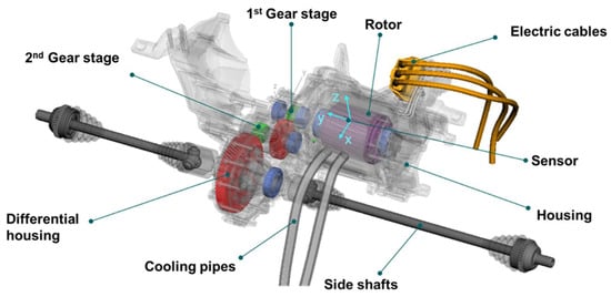
Figure 1.
eMBS drivetrain model.
By discretization of the rotor and stator using a multi-slice modeling approach, the electrical machine is divided into six slices (see Figure 2). This enables applying electromagnetic forces on each stator tooth according to the beveled angle of the stator and the orientation of the rotor sheet metal packages [6].
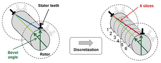
Figure 2.
Discretization of rotor and stator into six slices to apply electromagnetic forces.
The electrical machine under consideration in this paper is a PMSM with 36 stator teeth and six pole pairs at the rotor. By combining a finite element (FE) simulation of the stator-rotor cross Section of the electrical machine with a circuit simulation by Jaeger and Drichel et al. [6], the electromagnetic forces were calculated, including electromagnetic effects, such as slotting, magnetic saturation, and spatial harmonics, based on the approaches introduced by Herold et al. [3,20]. Various eccentricity states are incorporated in the FE simulation by modifying the air gap geometry and mesh. Based on this model, an electromagnetic force field was formed that stores the electromagnetic forces of the machine within the following five dimensions: Id-current, Iq-current, angle of rotation, eccentricity angle, and eccentricity radius. In order to apply the electromagnetic forces onto the rotor and stator of the electrical machine, a maximum torque per ampere (MTPA) look-up table is used, which stores the correlation between torque and rotation speed to Id-/Iq-current. In the displayed model, field-weakening and inverter effects, including pulse-width modulation and torque ripple, were not included, since their expected interlinking effects on the electromagnetic excitation could not be validated within this publication. Since validation of this described simulation approach with respect to measurements was already performed by Jaeger and Drichel et al. [6], it can be stated that the introduced simulation is suitable for simulating the transient structural dynamic behavior of the electric drivetrain. Since the applied electromagnetic forces and the modeling approaches used for the other machine elements are highly non-linear, and the goal of this publication is to study the effects of static eccentricity state variations. For that transient run-up, simulations with a run-up duration of seven seconds are performed to ensure that all relevant system resonances are excited by the rotation speed dependent excitation frequencies of the electromagnetic excitation orders. This is performed by applying the maximum torque onto the electric drivetrain and the steadily increasing the rotation speed of the electrical machine (see Figure 3). In order to ensure higher numerical stability during the transient run-up simulation, the torque is applied before the rotation speed is increased. While the rotation speeds increase up to 6500 rpm, the applied torque remains constant. Based on the simulation results of the transient run-up simulation, the critical operation point and dominant excitation orders can be identified, which is needed to perform a targeted optimization in the following Sections.

Figure 3.
Rotation speed and torque during a transient run-up simulation of the eMBS drivetrain model.
All the acceleration levels displayed during this publication are linear, unweighted peak values. No A-weighting or RMS averaging was applied. By visualizing the simulated acceleration in normal direction of the sensor on top of the electrical machine (see Figure 1), a variety of excitation orders and excited resonances can be observed during the whole run-up (see Figure 4). The displayed spectrogram was computed using a 20 kHz sampling rate, while a low-pass filter at 9 kHz was applied to prevent aliasing above the Nyquist frequency. To compute the short time Fourier transformation, a Hann window with 1024 points, 80% overlap, and 1025 samples was performed. Starting at lower frequencies, especially the orders of the electrical machines such as the 24th, 36th, and 72nd, are causing dominant order levels during the whole run-up, while exciting resonances, for example, at 1420 Hz, 2180 Hz, and 3370 Hz, leading to an increased acceleration amplitude. Although the excitations of the gear stages, which are also modeled in the drivetrain system models, are not under specific observations in this paper, it has to be noted that also those orders, e.g., the 21st, are relevant for the acceleration level simulated at the e-machine housing. Since no eccentricity state was applied during the run-up simulation, there are no characteristic sidebands forming along the main excitation orders of the electrical machine. In this case it has to be stated that modeling the excitations of the inverter of the electrical machine was not included, and these orders only occur due to antialiasing caused by the proximity to the Nyquist frequency (10 kHz) of the sampling rate.
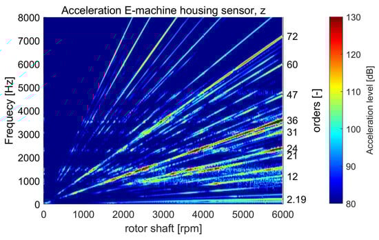
Figure 4.
Acceleration of e-machine housing sensors in z direction up to 8000 Hz while using a Hann window with 1024 points, 80% overlap and 1025 samples.
By comparing the total level of acceleration with the most dominant order levels, which are the 24th and 36th, it can be seen, that the excitation of the electrical machine contributes significantly to the acceleration levels, especially at rotation speeds above 2100 rpm (see Figure 5). The total level of acceleration represents the logarithmic sum of all spectral acceleration components (displayed in Figure 4) within the frequency range of 0 Hz to 8000 Hz without any weighting or filtering. In comparison to Figure 4, it can be stated that especially the 36th order of the electrical machine, which is both an excitation order of the stator teeth and of the pole pairs, is causing the highest acceleration level during the run-up. This critical operation point occurs at 5800 rpm and 152 dB and will be investigated in the following Sections.
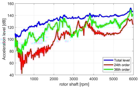
Figure 5.
Total and order level based on a transient acceleration signal from an e-machine housing sensor during run-up simulation.
4. Harmonic Analysis Based on the Excitations of an Electrical Machine
The investigations on the effects of static eccentricity are evaluated based on four sensor positions, each placed at 90° intervals along the outer housing surface of the electrical machine, centered in the middle of the slices used for electromagnetic force excitation (see Figure 6). These virtual sensors all orient their z-axis orthogonal to the corresponding housing surfaces so that in further visualizations of simulation results, always the acceleration in normal direction is considered. This arrangement of sensors is intended to ensure that an investigation of the static eccentricity shows global effects on the surface accelerations of the electrical machine. Furthermore, the study targets the simulated frequency range up to 8 kHz since this frequency spectrum can be considered as relevant based on the simulation results displayed in Figure 4.
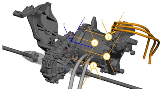
Figure 6.
eMBS drivetrain sensor positions (orange) with respect to the global coordinate system (blue).
In order to calculate the frequency response functions at the sensors, an axial, radial, and tangential excitation at all stator teeth in all slices are applied. The harmonic analysis for the FRF computation is conducted over a frequency range from 100 Hz to 8000 Hz with a frequency increment of 1 Hz. By comparing the FRFs of sensor 1 for all stator teeth excitations, it can be stated that the FRF amplitude in radial direction is the largest at all dominant resonances (see Figure 7). With respect to the hypothesis in Section 2 that the dominant effects in the air gap can be attributed to radial electromagnetic forces, it is summarized that excitations in radial directions seem to excite the system’s mode shapes dominantly. Therefore, within the following studies, only FRFs in radial directions are considered.
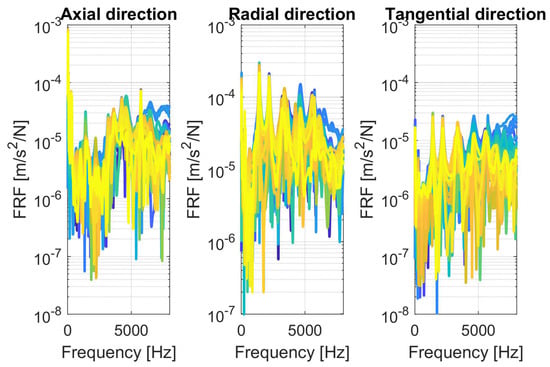
Figure 7.
FRF for axial, radial, and tangential direction of all stator teeth at sensor 1 (stator teeth 1: blue → stator teeth 36: yellow).
When displaying the FRF from the excitation from one representative tooth, distinct resonances are seen over the whole frequency spectrum (see Figure 8). Resonances become visible at all four FRFs of the sensors, for example, at 1500 Hz, 2200 Hz, and 5600 Hz. However, there are also resonances where only three out of four sensors, or fewer, show elevated amplitudes, such as at 1700 Hz, 3100 Hz, or 3600 Hz. Assuming a symmetric radial force distribution for the still concentric force pattern, it is suitable to derive an averaged FRF across all applied stator teeth excitations for each sensor. This enables the identification of resonances that are excited the most by the electromagnetic excitations. Since these dominant resonances cause the critical operation points, as were identified in Section 3, reducing their excitability will lead to a decrease in acceleration amplitude.
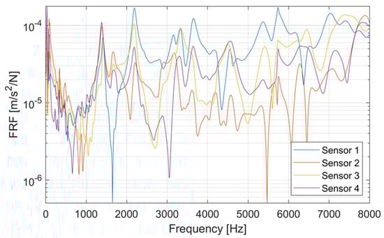
Figure 8.
FRF based on one representative stator teeth excitation for all sensors.
The averaged FRF reveals that Sensor 1 and Sensor 3 exhibit increased FRF amplitudes in comparison to Sensor 2 and Sensor 4 (see Figure 9). The averaging of the FRFs also indicates which resonances are primarily excited by the electromagnetic forces.
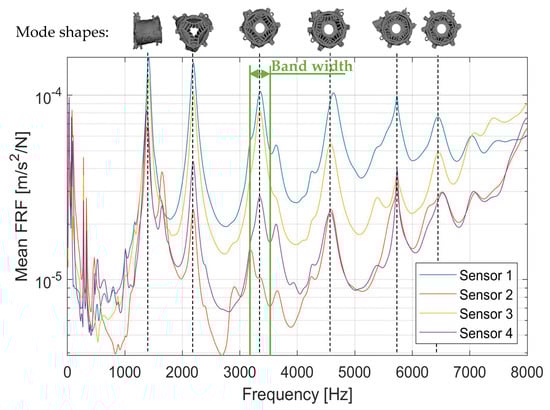
Figure 9.
Mean FRF based on all excitations for all sensors.
By conducting an eigenfrequency analysis of the assembled drivetrain while applying the loads acting on the drivetrain components during the time step of the critical operation point (see Figure 4), the corresponding mode shapes can be identified for every resonance identified within the FRFs (see Figure 9). Except for the mode shape at 1420 Hz, which is a bending mode, all other mode shapes that are responsible for large FRF amplitudes are breathing modes of the electrical machine. It can be seen that the 3rd, 4th, 5th, 6th, and 7th breathing modes of the electrical machine show a high excitability by the electromagnetic forces. This also correlates to the resonances identified in Figure 3, which have been identified as responsible for the critical operation points for the structural dynamic behavior of the drivetrain. Therefore, reducing the excitability of those breathing modes will result in an overall reduction in accelerations on the surfaces of the electrical machine.
The FRFs can further be used to determine the most beneficial direction of eccentricity for reducing the resonance response at the sensor positions. Based on the identified dominant excitation order, which is the 36th exciting the system at around 3200 Hz to 3500 Hz at the critical operation point identified in Section 3, the FRFs can also be averaged in this frequency band (see marked bandwidth at Figure 9). Performing that for all stator teeth individually reveals, which stator teeth excite the sensor location the least, indicating the most beneficial direction for static eccentricity. This step is carried out under the assumption of equal weighting of all frequency components and based on the hypothesis discussed in Section 2. It should be emphasized that the assumption of equal frequency and sensor weighting is application-dependent and can be adapted to reflect specific NVH targets or design constraints. Nevertheless, any adapted weighting requires validation to confirm its physical relevance and robustness.
The resulting frequency-averaged FRF shows that the sensor positions are excited with varying intensity by the individual stator tooth, and that each sensor exhibits a maximum response at the stator tooth closest to it (see Figure 10).
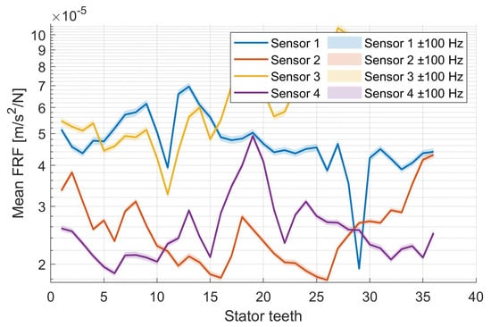
Figure 10.
Mean FRF for a frequency interval from 3200 Hz to 3500 Hz for all stator teeth and a varying frequency band of ±100 Hz.
The symmetry of the housing structure and therefore its sensitivity to radial excitations are also indicated by the individual stator tooth FRFs, since the maximum FRF amplitude of the sensors only varies up to 6.9 . Since a reduced FRF amplitude results in lower acceleration at the sensor locations, stator teeth with a low average FRF amplitude are better suited for use with a reduced air gap. As a consequence, eccentricity in the direction of stator teeth with low FRF amplitudes has less impact on the measured acceleration levels than eccentricity in the direction of teeth with high FRF amplitudes. Therefore, deliberately defining an eccentricity angle that aligns with the direction of the lowest average FRF amplitude will reduce the overall acceleration levels recorded by the sensors. To assess the robustness of the methodology, the frequency band used to average the FRF amplitudes for each stator tooth was varied by ±100 Hz. As shown in Figure 10, the resulting mean FRF values are only slightly affected, while the optimal direction for exciting the electrical machine remains unchanged. Therefore, an average reduction in amplitude can be achieved at all sensors when exciting at stator tooth 11. In order to determine the amount of eccentricity that benefits the acceleration levels the most, transient simulations with varying eccentricity states are carried out in the following Section.
5. Evaluating the Effects of an Increased Static Eccentricity Amplitude
In order to study the effects of an increased eccentricity in the direction of the stator tooth 11, multiple run-up simulations with a varying eccentricity state are performed. The eccentricity angle of 95°, which is the direction of stator teeth 11, is defined with respect to a global, fixed coordinate system. The following study on varying levels of eccentricity presents results only for sensors 1 and 3, as their FRF amplitudes are significantly higher than those of sensors 2 and 4, and consequently their impact on the measured acceleration signals is expected to be greater. Although the precise tolerances contributing to the static eccentricity of the investigated machine are unknown, Ruf et al. [8] determined that a similar machine exhibits static eccentricities of up to 125 µm. Therefore, increments of 25 µm were used to increase the eccentricity up to 125µm, which corresponds to approximately 18 % of the total air gap between the stator and rotor. By calculating the accelerations for a continuous run-up up to 6000 rpm, the effect of multiple eccentricity states can be visualized (see Figure 11). It can be observed that the eccentricity states in comparison to the concentric state lead to an increase or a decrease in total acceleration level at several operation conditions. At around 2400 rpm, where a bending mode at 1420 Hz is excited by the 36th excitation order (compare Figure 5), an increase in eccentricity leads to an increase in acceleration level of a maximum of 2 dB at a maximum eccentricity amplitude of 125 µm. In addition, it can be observed that for the critical operating point, the directional optimality is maintained as the eccentricity increases. However, the change in acceleration amplitude with each additional increment varies and decreases nonlinearly.
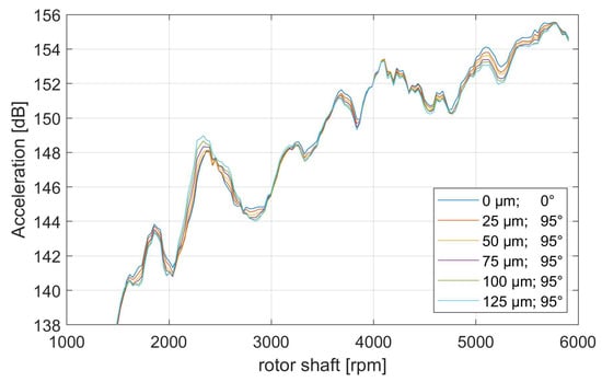
Figure 11.
Total acceleration level based on sensor 1 location for different eccentricity states (amplitude [µm] and angle [°]).
At higher rotation speeds, where the total acceleration level is the highest, it can be seen that by increasing the eccentricity amplitude, a decrease in total acceleration level is achieved, especially in case of the critical operation point from 5000 rpm to 5500 rpm, where again the 36th order excites the drivetrain dominantly (see Figure 12). However, this decrease is also minor and does not exceed 1.5 dB over the corresponding run-up interval.
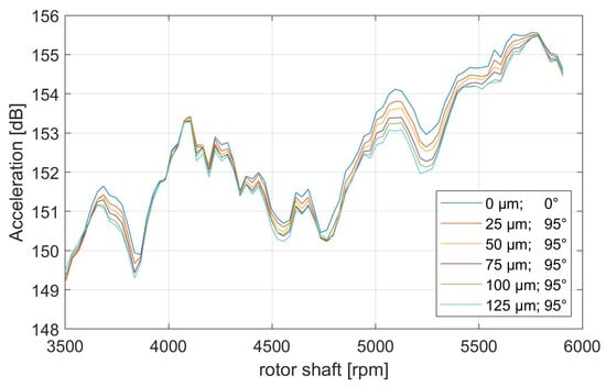
Figure 12.
Total acceleration level from 3500 rpm to 6000 rpm based on sensor 1 for different eccentricity states (amplitude [µm] and angle [°]).
When displaying the total level of acceleration for Sensor 3 (see Figure 13), it can be observed that an increase in eccentricity amplitude might also lead to a significant increase of over 7 dB in total acceleration level, for example, at 3800 rpm. However, also this sensor signal does indicate that an increase in eccentricity is able to decrease the total level, e.g., at 5700 rpm with a decrease of 1.5 dB.
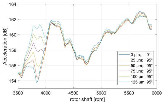
Figure 13.
Total acceleration level from 3500 rpm to 6000 rpm based on sensor 3 for different eccentricity states (amplitude [µm] and angle [°]).
All in all, it can be stated that in case of the considered drivetrain, the decrease in acceleration amplitude that occurs due to an increase in eccentricity amplitude does not exceed the 1.5 dB range. Therefore, a similarly significant decrease of up to 4 dB (A), as it was found by experiments conducted on an isolated electrical machine [14], has not been achieved. However, it has to be noted, that this amplitude is not directly comparable to the simulation results shown in Figure 12, as different electrical machines and assemblies have been used for the investigation, and the amplitudes differ in weighting, RMS, and frequency content considered. It should also be noted that the isolated electrical machine is directly mounted onto the test bench, resulting in a much stiffer assembly with lower damping compared to the modeled drivetrain assemblies, which include elastomeric mounts. Consequently, the influence of eccentricity variations on the vibration amplitude is expected to be more pronounced in the isolated machine. Due to these differing boundary conditions, the transfer path of the electromagnetic excitations cannot be directly compared between the bench setup and the integrated drivetrain model. It seems that the dominant bending and breathing modes of the electrical machine are excited independently of the excitation’s direction. This indicates that the mode shapes of the electrical machine, which are symmetric due to the cylindric shape of the machine housing and stator, dominate the structural dynamic behavior of the electrical machine within the drivetrain. Therefore, further investigations into designing machine housings are needed in order to significantly reduce the acceleration levels on the outer surfaces of the electrical machine. This could be achieved by generating asymmetric housing designs to tackle the highly oscillating symmetric breathing modes that typically occur at electrical machines.
6. Summary and Outlook
In electric vehicles, the lack of masking noise from combustion engines makes tonal excitations from the electric drivetrain more prominent and potentially disturbing. As NVH performance significantly shapes customer perception, its optimization has become a central development challenge, addressed increasingly through model-based methods and virtual prototypes to cut costs and shorten time-to-market. Based on previous studies, it is known, that varying static eccentricity states between the rotor and stator of an electrical machine, that occur due to manufacturing tolerances, can have a significant influence on the acceleration levels on the outer surfaces of the electrical machine [14]. However, a method to quantify the impact of eccentricity and therefore utilize it to improve the NVH behavior of electric drivetrains has not been developed.
To investigate the impact of static eccentricity on the NVH characteristics of electric drivetrains, this paper presents a newly developed simulation-driven methodology. By combining harmonic analysis with transient run-up simulations, excitation directions were identified that minimize the system’s vibrational response. It was observed, the relevant mode shapes responsible for the increased acceleration levels during the run-up simulation were identified as predominantly symmetric breathing modes, whose excitability appeared to be only slightly influenced by the direction of excitation. Despite targeting these favorable excitation directions, variations in the eccentricity amplitude led to only minor changes in overall acceleration levels, with reductions not exceeding 1.5 dB during the studied critical operation point. Consequently, the observed effect is small, and the conclusions regarding potential NVH improvements should be interpreted cautiously with respect to the demonstrated regime and metric set used for the shown analysis. This contrasts with prior experimental results on standalone machines, where significantly higher reductions were observed. However, it should be noted that both the approaches used to calculate acceleration amplitudes and the assemblies considered are not directly comparable. The latter is particularly relevant, as it strongly influences the stiffness of the eigenfrequencies and the transfer-path behavior of the machines, thereby affecting their sensitivity to the excitation of the natural frequencies. Therefore, future studies should aim for a direct experimental validation including a sensitivity analysis considering the variation in different manufacturing tolerances, such as rotor–stator non-homogeneous eccentricity, varying bearing stiffnesses, bearing clearance, and magnetic deviations, to provide a more detailed understanding of how the NVH behavior of an electrical drivetrain is influenced by manufacturing tolerances of the electrical machine. Due to the fact, that the symmetric breathing modes are excited independently of the direction of the main excitation direction of the electromagnetic forces, it is indicated that designing measures rather than parameterization of manufacturing parameters should be considered for further improving the NVH behavior of electric drivetrains. This does include setting up asymmetric housing designs, ribbing structures for lowering the surfaces velocities, or designing the transfer path from the excitation sources to the evaluation locations of the drivetrain.
Future research should therefore focus on structural optimization and design variant generation of the electric machine itself. Although these studies can be carried out numerically based on structural dynamic models, the modeling and simulation effort that has to be considered when conducting large design variant studies within the eMBS domain, requires to be automated modeling workflows and numerically efficient simulation approaches. In order to achieve that, characterizing the used models based on the model-based system engineering approach might help with automated modeling of new design variants while ensuring a numerically robust and therefore efficient modeling.
Author Contributions
Conceptualization J.M.; methodology, J.M.; formal analysis, J.M. and R.D.; writing—review and editing, J.M., G.J., R.D., and S.W.; visualization, J.M.; supervision, G.J. and S.W. All authors have read and agreed to the published version of the manuscript.
Funding
This research was funded by FVV e.V.
Data Availability Statement
Data are contained within the article.
Conflicts of Interest
The authors declare no conflicts of interest.
References
- Genuit, K. Sound-Engineering im Automobilbereich; Springer: Berlin/Heidelberg, Germany, 2010. [Google Scholar]
- Müller, J.; Jacobs, G.; Ramm, M.; Wischmann, S.; Jagla, P.; Berroth, J. Model-based NVH optimization of a tractor drivetrain during different phases of a design adaption. Forsch. Ingenieurwes. 2023, 87, 363–373. [Google Scholar] [CrossRef]
- Herold, T.; Lange, E.; Hameyer, K. System Simulation of a PMSM Servo Drive Using Field-Circuit Coupling. IEEE Trans. Magn. 2011, 47, 938–941. [Google Scholar] [CrossRef]
- Luzardo, E.J.; Galluzzi, R.; Escobar, G.; Juarez, J. Design optimization of a PMSM stator for powertrain applica-tions considering NVH behavior. In Proceedings of the 2024 International Symposium on Electromobility (ISEM), Guadalajara, Mexico, 18–20 September 2024; pp. 1–7. [Google Scholar] [CrossRef]
- Franck, M.; Rickwärtz, J.P.; Butterweck, D.; Nell, M.; Hameyer, K. Transient System Model for the Analysis of Structural Dynamic Interactions of Electric Drivetrains. Energies 2021, 14, 1108. [Google Scholar] [CrossRef]
- Jaeger, M.; Drichel, P.; Müller-Giebeler, M.; Hameyer, K.; Jacobs, G.; Vorländer, M. Erweiterung NVH Simula-tionsmodell: Erweiterung der Simulationsmöglichkeiten für Maschinenakustische Untersuchungen an E-Motive-Antrieben im Kontext zur Fahrzeugstruktur; Forschungsvereinigung Antriebstechnik (FVA): Frankfurt, Germany, 2020. [Google Scholar]
- Ebrahimi, B.M.; Faiz, J.; Roshtkhari, M.J. Static-, Dynamic-, and Mixed-Eccentricity Fault Diagnoses in Perma-nent-Magnet Synchronous Motors. IEEE Trans. Ind. Electron. 2009, 56, 4727–4739. [Google Scholar] [CrossRef]
- Ruf, A.; Schröder, M.; Putri, A.K.; Konrad, R.; Franck, D.; Hameyer, K. Analysis and determination of mechanical bearing load caused by unbalanced magentic pull. COMPEL 2015, 35, 728–743, 2015. [Google Scholar] [CrossRef]
- Aggarwal, A.; Strangas, E.G.; Agapiou, J. Analysis of Unbalanced Magnetic Pull in PMSM Due to Static Eccen-tricity. In Proceedings of the 2019 IEEE Energy Conversion Congress and Exposition (ECCE), Baltimore, MD, USA, 29 September–3 October 2019; pp. 4507–4514. [Google Scholar] [CrossRef]
- Design Methodology for Future Products Data Driven, Agile and Flexible Dieter Krause, Emil Heyden; Springer: Berlin/Heidelberg, Germany, 2021.
- Kim, D.-J.; Kim, H.-J.; Hong, J.-P.; Park, C.-J. Estimation of Acoustic Noise and Vibration in an Induction Machine Considering Rotor Eccentricity. IEEE Trans. Magn. 2014, 50, 857–860. [Google Scholar] [CrossRef]
- Lin, F.; Zuo, S.; Deng, W. Impact of rotor eccentricity on electromagnetic vibration and noise of permanent magnet synchronous motor. J. Vibroeng. 2018, 20, 923–935. [Google Scholar] [CrossRef]
- Zhao, M.; Wang, X.; Liu, L.; Tu, X.; Yang, Q. Optimization of PMSM for EV based on Vibration and Noise Suppression. Appl. Comput. Electromagn. Soc. J. 2024, 39, 64–80. [Google Scholar] [CrossRef]
- Deng, W.; Zuo, S.; Chen, W.; Qian, Z.; Qian, C.; Cao, W. Comparison of Eccentricity Impact on Electromagnetic Forces in Internal- and External-Rotor Permanent Magnet Synchronous Motors. IEEE Trans. Transp. Electrific. 2022, 8, 1242–1254. [Google Scholar] [CrossRef]
- Jung, W.-S.; Kim, Y.-S.; Choi, Y.-T.; Shin, K.-H.; Choi, J.-Y. Electromagnetic and NVH Characteristic Analysis of Eccentric State for Surface-Mounted Permanent Magnet Synchronous Generators in Wave Power Applications. Appl. Sci. 2025, 15, 9697. [Google Scholar] [CrossRef]
- Müller, J.; Franck, M.; Jansen, K.; Höpfner, G.; Berroth, J.; Jacobs, G.; Hameyer, K. Experimental Determination of Influences of Static Eccentricities on the Structural Dynamic Behav-ior of a Permanent Magnet Synchronous Machine. Machines 2024, 12, 649. [Google Scholar] [CrossRef]
- Hermle, M.; Kesten, J.; Doppelbauer, M.; Eberhard, P. Dynamic modeling of a synchronous reluctance machine for transient simulation of vibrations under variable rotor magnetization. Proc. Inst. Mech. Eng. Part K J. Multi-Body Dyn. 2024, 238, 52–63. [Google Scholar] [CrossRef]
- Weber, C.; Banaschek, K.; Niemann, G. Formänderung und Profilrücknahme bei Gerad- und Schrägverzahnten Rädern; Vieweg: Braunschweig, Germany, 1953. [Google Scholar]
- Craig, R.R.; Bampton, M.C.C. Coupling of substructures for dynamic analyses. AIAA J. 1968, 6, 1313–1319. [Google Scholar] [CrossRef]
- Franck, D.; Herold, T.; Hameyer, K. Transient acoustic simulations of electrical drive-trains. In Proceedings of the AIA-DAGA 2013 International Conference on Acoustics, Merano, Italy, 18–21 March 2013. [Google Scholar]


Disclaimer/Publisher’s Note: The statements, opinions and data contained in all publications are solely those of the individual author(s) and contributor(s) and not of MDPI and/or the editor(s). MDPI and/or the editor(s) disclaim responsibility for any injury to people or property resulting from any ideas, methods, instructions or products referred to in the content. |
© 2025 by the authors. Licensee MDPI, Basel, Switzerland. This article is an open access article distributed under the terms and conditions of the Creative Commons Attribution (CC BY) license (https://creativecommons.org/licenses/by/4.0/).