You are currently viewing a new version of our website. To view the old version click .
Machines
  • Article
  • Open Access

2 November 2025

Belt Sanding Robot for Large Convex Surfaces Featuring SEA Arms and an Active Re-Tensioner with PI Force Control

,
,
and
1
Department of Convergence Mechanical Engineering, Hanyang University, Seoul 04763, Republic of Korea
2
School of Mechanical Engineering, Hanyang University, Seoul 04763, Republic of Korea
3
Department of Mechanical Engineering, BK21 FOUR ERICA-ACE Center, Hanyang University, Ansan 15588, Republic of Korea
*
Authors to whom correspondence should be addressed.
This article belongs to the Special Issue Recent Developments in Machine Design, Automation and Robotics, Second Edition

Abstract

This study presents a belt sanding robot for large convex surfaces together with a proportional–integral force control method. Sanding belt tension strongly affects area coverage and spatial normal-force uniformity on large curved surfaces; existing approaches typically use fixed tool positions or lack active tension regulation, which limits coverage and makes force distribution difficult to control. The mechanism consists of two series elastic actuator arms and an active re-tensioner that adjusts belt tension during contact. In contrast to a conventional belt sander, the series elastic configuration enables indirect estimation of the reaction force without load cells and provides compliant interaction with contact transients. The system is evaluated on curved steel plates using vertical scans with a belt width of 50 mm and a drive wheel speed of 300 rpm. Performance is reported for two target curvature values, namely 0.47 and 1.37, with five trials for each condition. The control objective is a constant normal force along the contact, achieved through proportional–integral control of the arms for normal-force tracking and the re-tensioner for belt tension regulation. To quantify spatial force uniformity, the distribution rate is defined as the ratio of the difference between the maximum and minimum normal forces to the maximum normal force measured across the belt–workpiece contact region. Compared with a simple belt sander baseline, the proposed system increased the sanded area coverage by 31.85%, from 62.20% to 94.05%, at the curvature value of 0.47, and by 8.49%, from 81.21% to 89.70%, at the curvature value of 1.37. The distribution rate improved by 113% at the curvature value of 0.47 and by 16.7% at the curvature value of 1.37. Under identical operating conditions of 50 mm belt width, 300 rpm, and five repeated trials, these results indicate higher area coverage and more uniform force distribution relative to the baseline.

1. Introduction

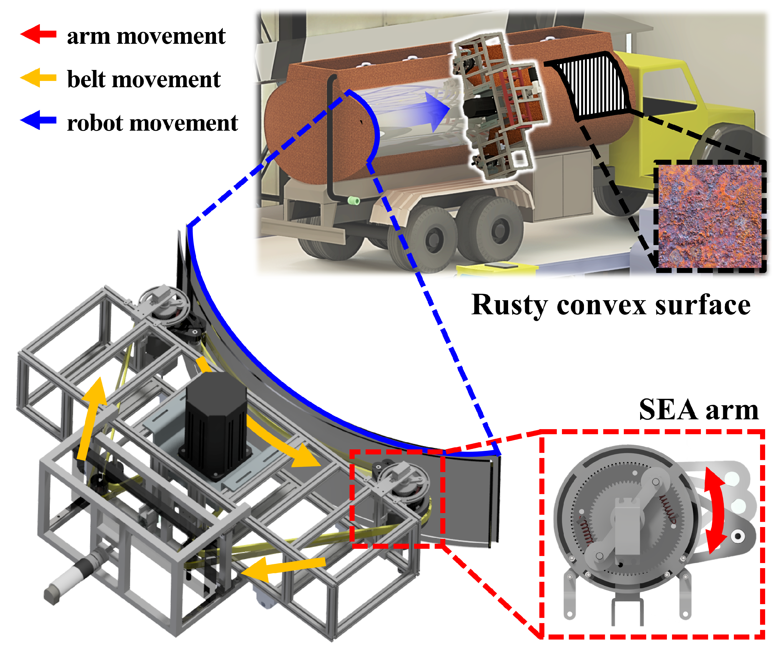
Sanding, which is the process of making something smooth by rubbing it with something rough, is a crucial process in various industries, ranging from manufacturing to maintenance and repair. It serves multiple purposes, such as improving the aesthetic appeal of surfaces, preparing for subsequent painting or coating, and removing unwanted materials such as rust or other contaminants for safety. However, traditional sanding processes rely predominantly on manual labor, which presents several challenges. First, manual sanding exposes workers to continuous vibrations that can have detrimental musculoskeletal health effects over time. Second, maintaining consistency while manually sanding large areas is difficult because of the inherent variability in human performance, which often results in uneven finishes and makes it almost impossible to restore over-sanded surfaces. Finally, manual sanding generates dust that can harm the respiratory health of workers if not properly managed with additional facilities or protective gear. Owing to the challenges associated with manual sanding, there is an increasing need for automation. Automated solutions can not only address the aforementioned issues but also enhance productivity and reduce operational costs. To meet such needs, this study proposes a mechanism adapting a series elastic actuator (SEA) and a re-tensioner as a new way to control the tension and normal force of a sanding robot for large-area convex surfaces, as shown in Figure 1.
Figure 1. Proposed large-area convex belt sanding robot.
Abrasion robots were grouped by mechanism into belt, orbit, and wheel modules. Prior work spans belt grinding and polishing, orbit polishing heads, and wheel grinding for seams and edges [,,]. Most reported systems target small parts or locally planar and strip-like regions such as turbine blades, weld seams, and furniture panels [,]. By contrast, large, doubly curved surfaces demand both high structural capacity and precise coordination of position and contact force over a wide interface, which remains difficult in practice [,,]. Recent work on compliant/SEA-equipped grinding end-effectors and force-planning on complex curved parts further underscores the need for active force/tension regulation in large-area finishing [,,]. Performance is often summarized by coverage, roughness, or mark suppression; only a few studies explicitly quantify how normal force is distributed spatially across large contact areas []. This gap matters because non-uniform force across the belt–workpiece interface degrades coverage and produces local over-removal on convex geometries.
Against this backdrop, our study frames a concrete control problem for large-area convex sanding: regulating belt tension and the spatial distribution of normal force across the full belt width. We adopt series elastic actuators on the sanding arms to estimate reaction force indirectly at the contact without load cells and to provide compliance to contact transients under vibration and dust typical of belt abrasion. In our previous passive-arm experiments, distinct groove marks indicated sudden jumps in normal force at the contact []. Integrating SEAs reduces the mechanical output impedance of the arms and improves tolerance to impact loads, mitigating those jumps. In addition, an active re-tensioner is introduced to maintain appropriate belt tension along the contacting span, addressing belt tracking and tension variability that conventional arrangements do not actively control. These design choices directly target the two limitations above—limited instantaneous coverage and non-uniform spatial force—and set up the measurable objectives evaluated in this paper.
The re-tensioner mitigates the challenges of belt detachment and escapes from its designated track when transitioning to a multi-wheel belt system. Owing to the limitations stemming from their primary purpose, only two wheels that did not contact the target surface were left capable of guiding the belt track. Along with the attached idlers, this configuration allowed the maintenance of optimal belt tension, ensuring that the belt remained securely on track throughout the sanding process. In doing so, we not only mitigated the risks associated with belt detachment but also optimized the overall efficiency of our multi-wheel belt system for improved performance.
Large-area finishing on doubly curved workpieces is limited by two concrete factors. Prior systems typically present a narrow instantaneous contact patch and operate from fixed tool positions, which constrains the achievable coverage across the belt width during a single pass. In addition, the spatial distribution of normal force across the belt–workpiece interface is often non-uniform, leading to locally excessive removal and visible banding rather than consistent surface quality.
This study addresses these gaps with measurable objectives evaluated under controlled operating conditions. The first objective is to achieve full-width contact across the nominal belt span during each vertical pass so that the belt engages the entire width rather than a narrow strip. The second objective is to promote uniform normal-force distribution across the contact region, reducing spatial variation relative to a conventional belt sander.
The evaluation focuses on steel plates with convex curvature representative of the target application. Operating conditions reported in the following sections include a belt width of 50 mm, vertical feed of 50 mm/min, and drive wheel speed of 300 rpm. Stating the objectives in terms of belt width coverage and force uniformity links the mechanism and control choices to practical finishing outcomes on large convex surfaces.
The sanding belt tension is controlled using the proportional–integral (PI) control method to ensure optimal belt tightness throughout the sanding process. This allows consistent and uniform sanding and avoids surface warping. PI control is also used to regulate the reaction force applied to the target surface. This enables adaptive and compliant interactions between the sanding belt and convex target surfaces, accommodating variations in curvature, and preventing uneven surfaces from excessive forces. By adjusting the applied force based on real-time feedback, damage to delicate surfaces can be prevented while maintaining effective and well-distributed material removal.
The remainder of this paper is organized as follows. Section 2 describes the robot mechanism, including the kinematics and dynamic modeling. Section 3 describes the robot control. Section 4 presents the experimental setup and corresponding results. Finally, Section 5 concludes the paper.

2. Robot Design

The proposed sanding robot is described in this section. After explaining the overall structure, the sanding module, re-tensioner, and the three-degrees-of-freedom (3-DOF) moving stage are described.

2.1. Overall Structure

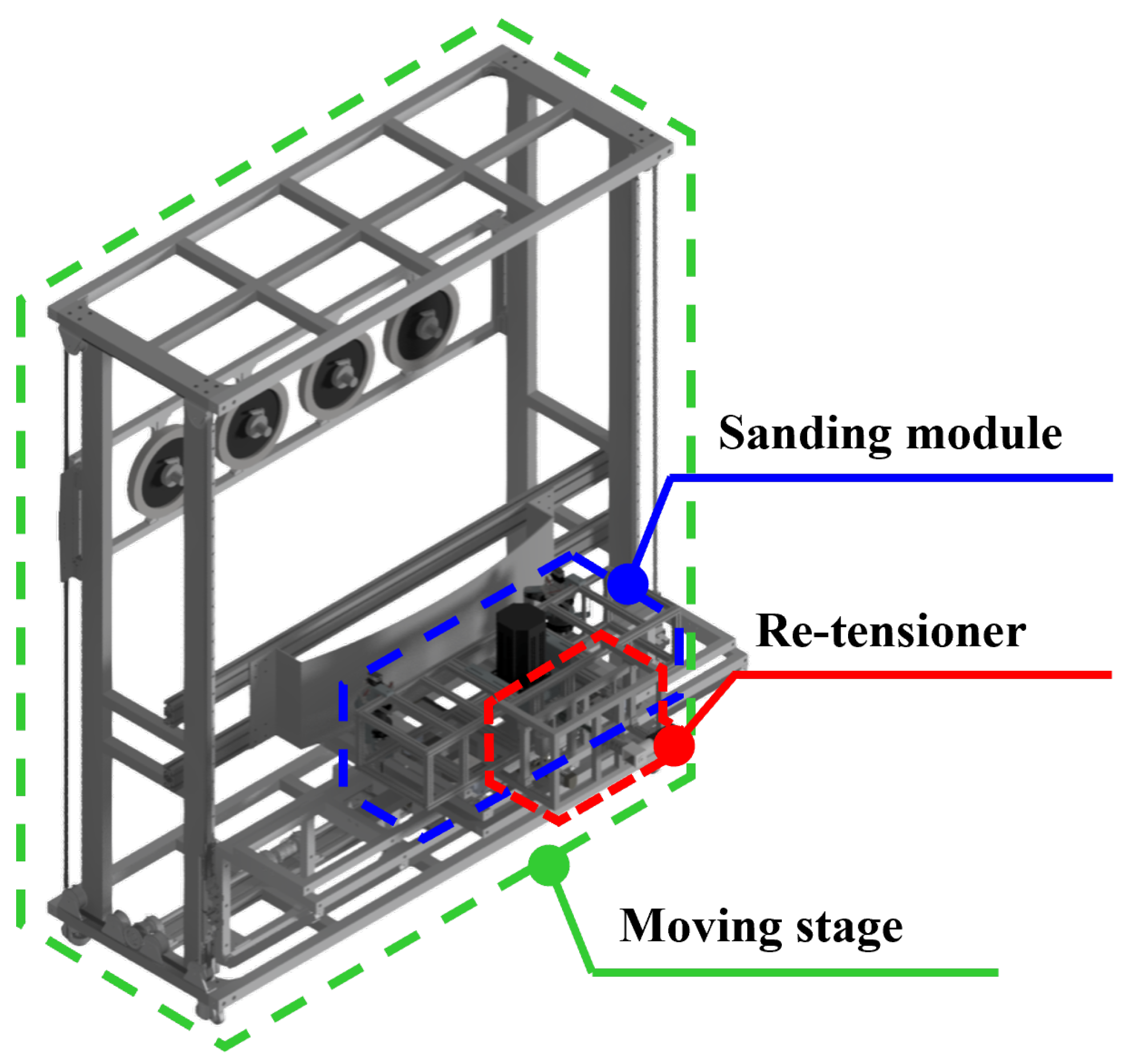
Figure 2 illustrates the overall robot design suggested for large-area convex sanding. The robot is largely composed of the following three components: a belt sanding module, a re-tensioner, and a moving stage. Sanding begins when the target object approaches the moving stage. Once contact is made, the SEA arms of the sanding module are actuated to follow the target surface curvature while tracking the reference force. During this process, the tension throughout the contacting side of the belt is adjusted to obtain the proper tension for sanding by moving the re-tensioner idlers with a ball screw.
Figure 2. Overall design of the proposed sanding robot.

2.2. Sanding Module

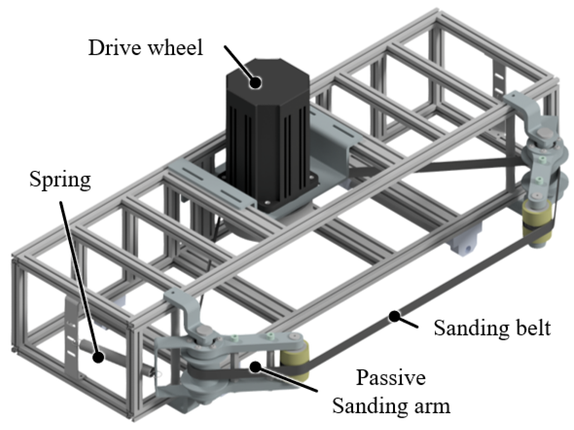
Figure 3 shows the sanding module, which is capable of sanding the target with a sanding belt. The sanding belt is rotated by a driving BLDC motor (TM13-D2021-S-4P-K-SG DC24V 2KW, motorbank, Seoul, Republic of Korea), controlled by an MD2K motor driver, and supported by the two contact wheels, two idlers on the sanding arms, and two additional idlers on the re-tensioner. A DC power supply (TS6015A 60 V/15 A 900 W, Toyotech, Seoul, Republic of Korea) is used to ensure stable power delivery to the driving wheel. For the sanding arm, a reaction force-sensing SEA mechanism (RFSEA), in which the spring is located before transmission, is applied to measure and control the torque applied to the arms []. The sanding arms measure the torque exerted on both arms, calculate the reaction force from the target surface using linear springs and rotary encoders, and track the desired force. The upper parts, indicated in blue in Figure 3, are responsible for the angle input, while the lower parts (indicated in red) measure the actual rotated angle. The servo motors on each arm (B250 Brushless Servo, Highest, Seoul, Republic of Korea) were chosen such that they could generate more than 2 Nm at a voltage of 6 V for an estimated reaction force of 10 N. Four linear springs with lengths of 40 mm and spring constant k of 3.34 N/mm with an initial tension F 0 of 12.75 N were used and aligned in the rotational direction. A rotary encoder (E50S8-8000-3-V-24, Autonics, Busan, Republic of Korea) with a resolution of 8000 was used to measure the arm rotation angle and calculate the reaction force at each arm.
Figure 3. Overall sanding module design.

2.3. Re-Tensioner

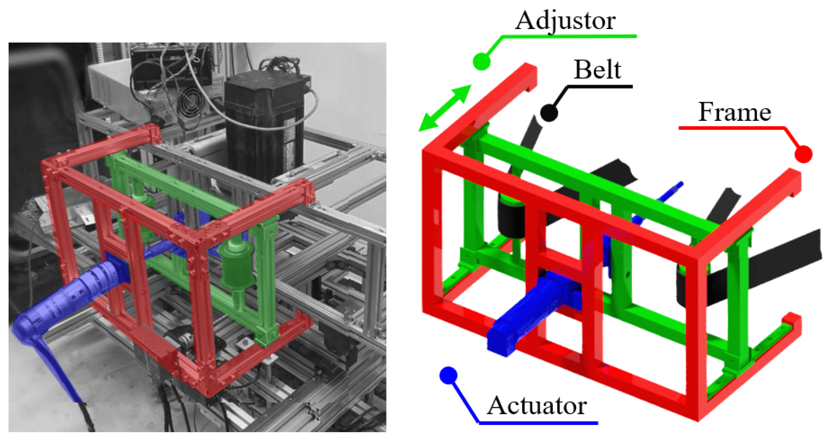
As shown in Figure 4, the re-tensioner pulls the belt from the target object or vice versa to maintain the proper tension. An adjuster moving back and forth with a ball screw with a pitch lead of 4 mm, a diameter of 12 mm, and a DC motor (PGM42-4566, 1/4, 12 V, motorbank, Seoul, Republic of Korea) was used. Two idlers are attached to the actuator to guide the belt and prevent it from detaching.
Figure 4. Overall re-tensioner module design.

2.4. Moving Stage

In addition to the horizontal motion that is shown approaching the target surface, vertical motion was also considered because it would be unreasonable to neglect it when the operating time is an important factor in sanding large-area convex surfaces. A BLDC motor (PG42BL4261E1, 1/49, 24 V, motorbank, Republic of Korea) with a deceleration rate of 1/49 was used to achieve a high torque of 5 Nm, given it should move the entire robot by itself.

2.5. Sanding Robot Kinematics

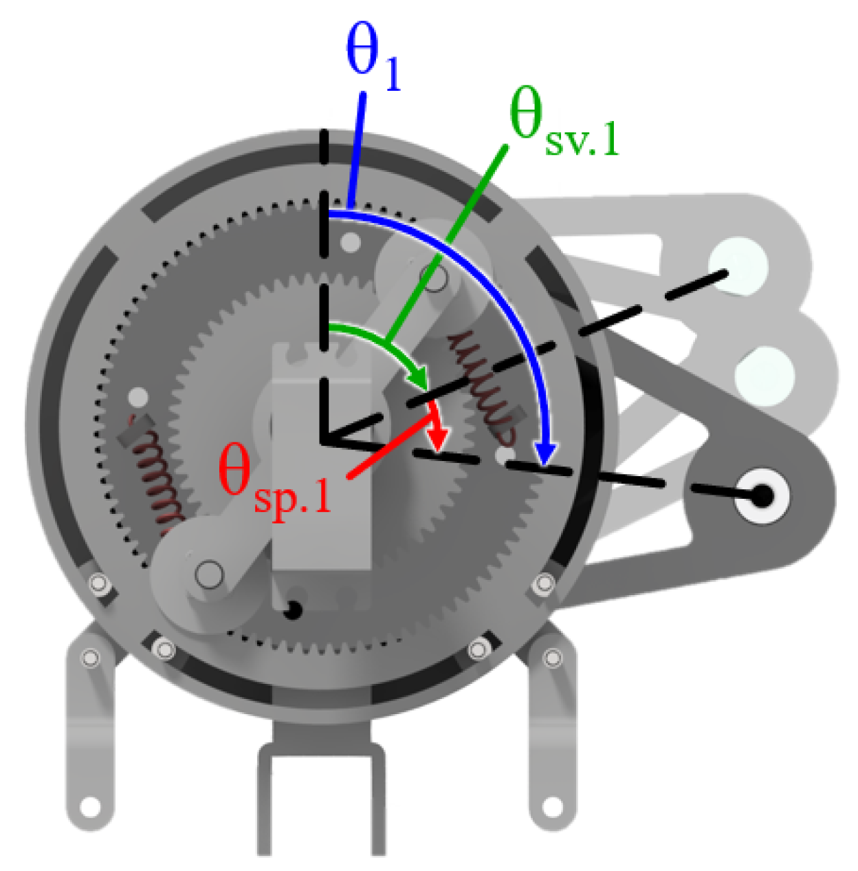
Figure 5 shows how the angles in each SEA arm are structured. θ 1 is the total angle rotated by the SEA arm on wheel D while θ 2 indicates the same on wheel E. θ SV1 is the angle rotated by the servo motor and θ SP1 is the angle generated by the lengthened spring. θ 1 and θ 2 can be separately and actively adjusted for a more evenly distributed surface normal force, leading to uniform sanding on the contact area between the sanding belt and convex target surface.
Figure 5. Angles on the SEA arm.
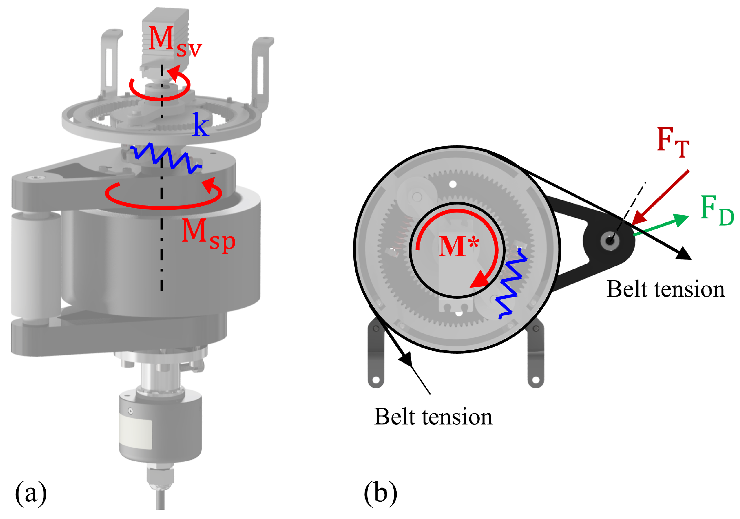
Figure 6 shows how the torque from the servo motor is transferred to the contact point on point D. The torque applied by a servo motor, M sv , is transferred through the planetary gear set. In this gear set, a ring gear with 90 teeth is stationary and fixed to the frame. The sun gear has 60 teeth, and two planet gears with 15 teeth each form a 1:2.5 rotational angular speed ratio for the carrier, which is a line connecting the centers of the planet gears and sun gear. This enables the carrier angle to range from 0° to 64° and remains sufficiently strong to maintain θ SV against the moment generated from F T .
Figure 6. SEA arm force balance with two-point support, with annotations marking the applied, belt, and reaction forces: (a) side view and (b) top view.
The angle rotated by the servo motor ( θ SV ) and the angle measured by the rotary encoder at the base ( θ 1 ) differ because of the presence of springs, which contribute to an additional angle ( θ SP ). The notation and units used in this section are summarized in Table 1. These springs connect the lower and upper parts of the SEA arm. The springs also help the tip of the arm to not press the target surface too tightly, which can lead to a jump in the normal force applied, resulting in uneven sanding quality.
Table 1. Symbols and units used in the sanding robot kinematics.
The relationship between the torques asserted on one SEA arm is expressed as follows:
M s v * + M s p = M *
M * + M D + M T = 0
where M s v * is the torque amplified by the gear, M SP is the torque caused by spring force, M T is the torque caused by F T , and M D is torque originated from force F D .
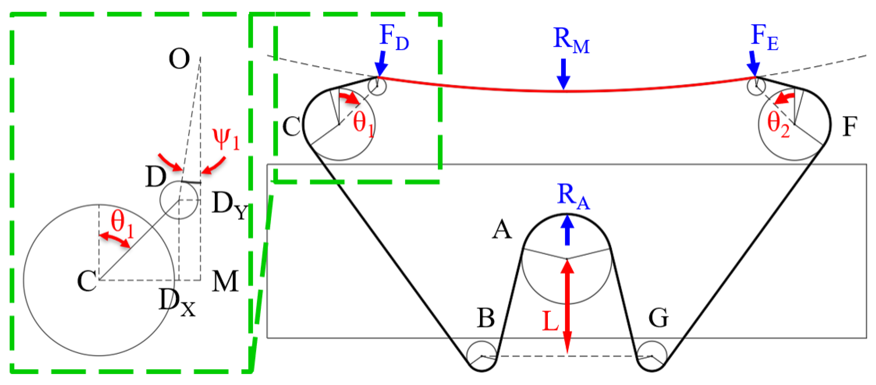
Figure 7 shows the overall belt configuration during the sanding process, where point O is the center of the target surface. F D and F E are the forces exerted on D and E, respectively, on the contact points with the target surface; R A is the force exerted on the drive wheel from the belt tension; and R D , R E , and R M are the reaction forces on the target surface, where M is the midpoint between D and E on the target surface. For the analysis associated with Equations (3)–(7) and the free-body diagrams, we adopt three working assumptions that align with the reported operating regime. The belt is treated as inextensible on each straight or wrapped segment during a pass, so tension within a given segment is uniform and variations arise from geometry rather than stretch. The support wheels at C and D are bearing-mounted and do not transmit appreciable resisting moments; therefore, support moments are neglected in the two-point contact case. The contact geometry is evaluated within the convex curvature range represented by the tested plates in this study; behavior outside this range may require additional compliance or contact modeling. These assumptions justify the quasi-static simplifications used in the force balance and are referenced alongside Figure 7.
Ψ 1 = sin 1 OD ¯ DD Y ¯ = sin 1 378 90 sin θ 1 r t + r E
α = π 3 + Δ θ s p
Δ X s p = ( 40 2 15 2 ) 1 2 2 cos α
F T = 2 T sin Ψ 1 cos 1 R + r 90 θ 1 Ψ 1
F D = M * + M T 90 sin ( θ 1 ψ 1 ) = 2 k Δ X s p + F 0 r g e a r cos 1 2 α + F T cos 1 2 α Ψ 1 90 sin ( θ 1 Ψ 1 )
Figure 7. Overall belt configuration of the two-point support during sanding.
Wang et al. [] introduced a method to calculate the force F T exerted on an abrasion belt when a circular target object is pressed against it. The bearings on wheels C and D allow the moment caused by belt tension to be negligible in the two-point contact situation. Using this method, M D can be calculated, leading to the calculation of F D and F E , which are with respect to the servo angles on each arm, θ 1 and θ 2 , and the radius of the target surface, r t , in (7), where 90 mm is the distance between the centers of wheels C, D, E, and F, and 37.5 mm is the distance between the center of the sun gear and that of one planet gear. Because linear coil springs were used, the equation for estimating F D is nonlinear.
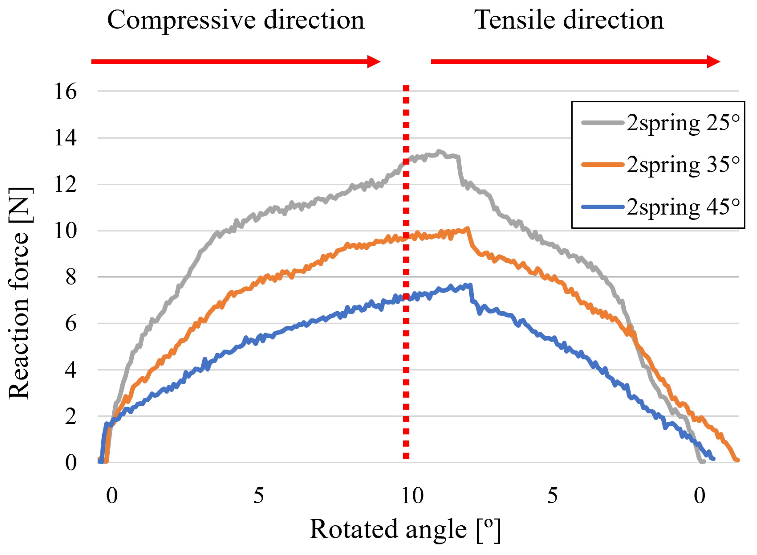
Figure 8 shows details of the reaction force with respect to the sanding arm rotated angle for two springs on a planar surface. The SEA arms affect the force exerted on the plane target surface at different θ 1 and k. The SEA arm moved toward a 3 mm thick steel plate for 9 s and then moved in the opposite direction at the same constant speed. The reaction force was measured using four load cells (SBA-100L, CAS) at each corner of the rectangular target surface at 70 signals per second. The appropriate sanding operation time and force were determined in the pre-conducted experiments. There was a force oscillation in the 0.6 N gap when the spring constant was low, resulting in the use of at least two springs, as described above. It also shows that the measured force value is within an error range of 5% of the predicted value, proving its suitability for sensing.
Figure 8. Reaction force with respect to the rotated angle for the two-spring cases.
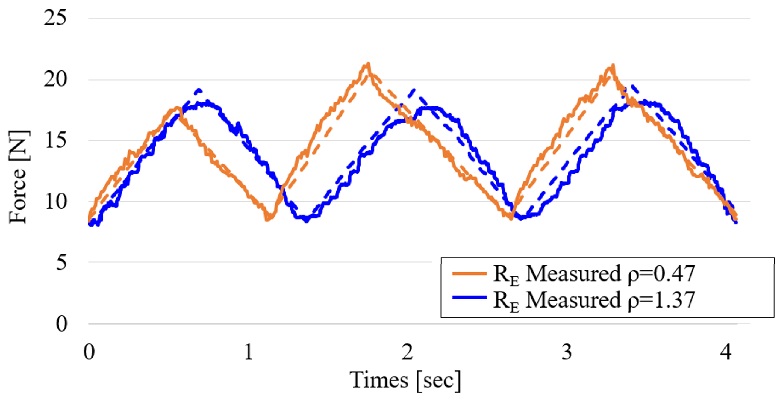
Figure 9 shows a comparison between the mechanism’s calculated force F E in the y-direction and the measured R E value with respect to time, which represents the SEA arms’ sensing ability on convex target surfaces without any control method applied. With a maximum gap of 2% in the maximum value area where actual sanding occurs, these results prove the effective sensing ability of the SEA sanding arms.
Figure 9. Comparison of calculated and measured R E over time in the y-direction for two convex target surfaces. Dotted lines indicate calculated values and solid lines indicate experimental measurements.

3. Control System

Simple PI control associated with an active SEA system is more desirable than impedance control when the goal is to maintain a constant force over time with limited dynamic interaction []. In classical interaction control, impedance control shapes a desired dynamic relation between motion and force at the contact, which is advantageous for tasks requiring active rendering of inertia, damping, or stiffness and for broadband interaction []. Our application targets constant-force tracking under limited interaction dynamics: the belt–workpiece contact is operated in a quasi-static regime, the series elastic actuators provide intrinsic compliance, and the control bandwidth is restricted by belt dynamics and structural vibration. Under these assumptions, a force-regulating PI outer loop on the SEA arms, combined with PI tension regulation for the re-tensioner, achieves steady-state accuracy without the parameter identification and gain scheduling typically required to render a stable target impedance over a wide frequency range. The chosen architecture therefore prioritizes low-frequency force accuracy and repeatability rather than interaction rendering, which aligns with the finishing objective of uniform material removal over large convex areas. Furthermore, without the need to change the input variables, such as the material stiffness or damping of the target surface, PI control is more suitable for robust control.
PI controllers are mainly used for processes where precise and steady-state accuracy is required, whereas rapid change is insignificant [,]. Adding an integral component to the proportional error terms, as in P control, eliminates the steady-state error and provides balance between the response speed and error correction. Table 2 summarizes the selected PI gains for the SEA arm and the re-tensioner together with the unified control targets.
Table 2. PI gains and control targets.
The proportional and integral gains were determined by experiment-driven step-response tuning on the instrumented setup. We first applied P control and increased K P until fast tracking was achieved without sustained oscillation, then introduced a small integral term to eliminate steady-state error under the reported operating conditions. The gains used in all experiments are K P = 0.3 , K I = 0.1 for the SEA arm force loop and K P = 0.3 , K I = 0.05 for the belt tension loop. During belt operation, evaluation used a simple moving-average filter as described to address periodic vibration from the belt joint.
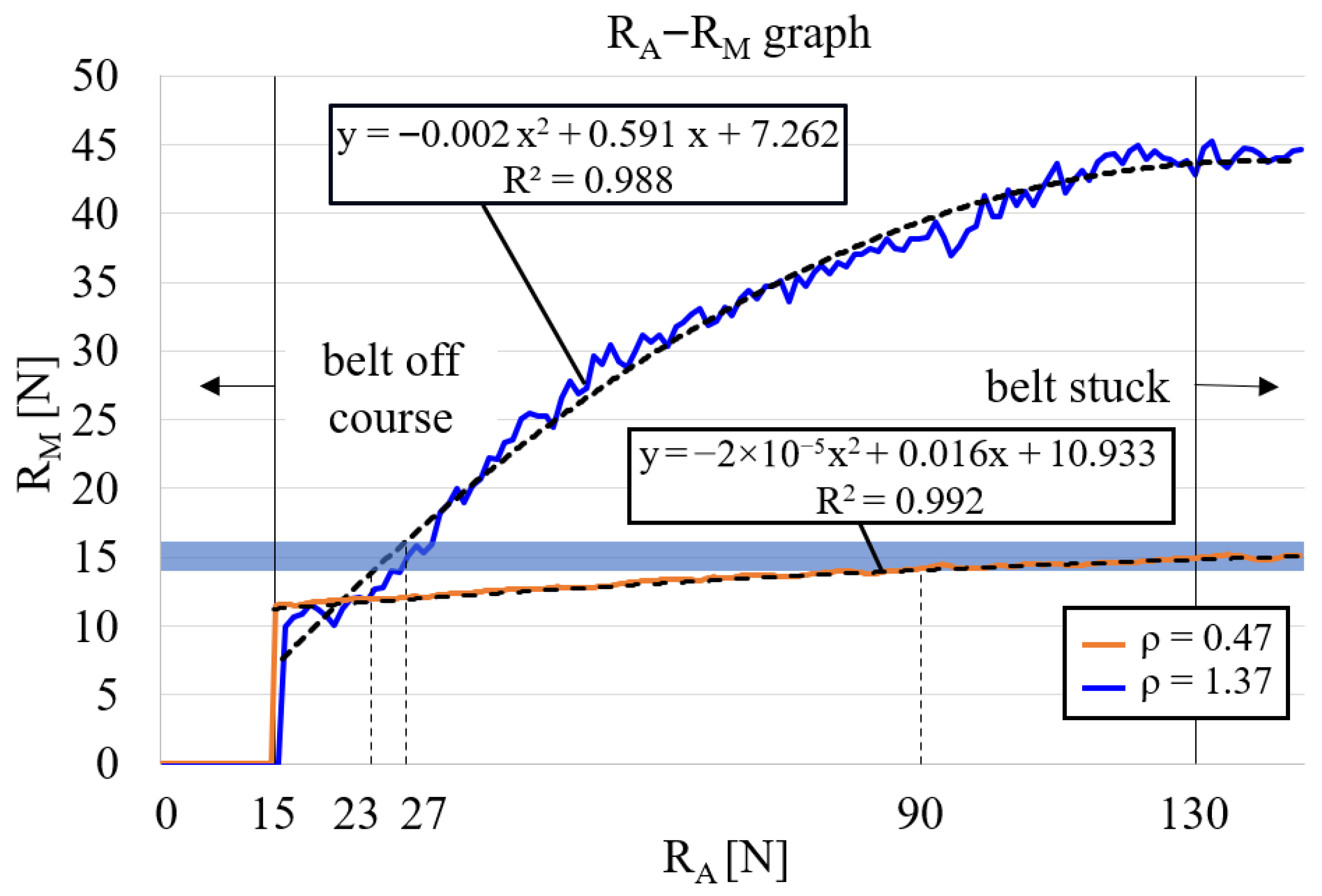
The relationship between R A , which is the force exerted on the drive wheel by the belt tension, and R M , which is the force at the midpoint of the target surface from the belt tension, was empirically determined, as shown in Figure 10. There was insufficient tension on the belt to rotate when R A was below 15 N, and the belt rotation was stopped because the tension was too high when R A exceeded 130 N.
Figure 10. Empirical relationship between R A and R M in cases of two target surfaces.
For each curvature, the mid-contact force R M was fitted as a quadratic function of the drive wheel proxy R A (both in newtons). The fitted relations are
R M = 0.002 R A 2 + 0.591 R A + 7.262 ( ρ = 1.37 , R 2 = 0.988 ) ,
R M = 0.00002 R A 2 + 0.016 R A + 10.933 ( ρ = 0.47 , R 2 = 0.992 ) .
where ρ denotes the curvature value used in the tests.
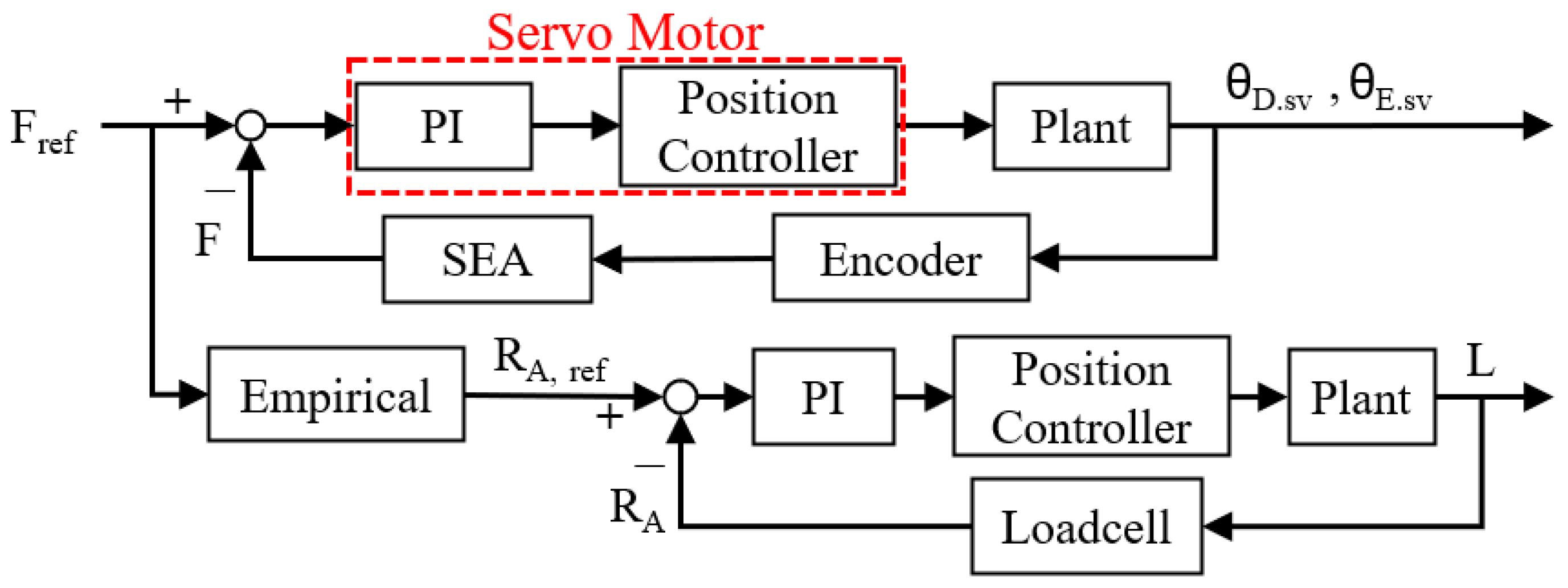
These second-order least-square fits are used within the observed operating range ( R A = 15 –130 N) reported in Figure 10. These relationship functions were chosen and used as an empirical block on the block diagram shown in Figure 11.
Figure 11. Control of the SEA arms and L.
The drive wheel proxy R A and mid-contact force R M were related by a quadratic fit, explicitly limited to the observed operating range ( R A = 15 130 N ) . Although the number of sweeps per curvature was limited, the fits exhibited high quality and the residuals were approximately zero-mean without systematic trends. The mapping was then used as the reference-generation block in the control architecture, and its consistency was verified in subsequent closed-loop experiments using independent load cell measurements at points D, M, and E. Within the stated range, the mapping provides practically sufficient accuracy for reference generation.
The control of the force acting on the contact point on the SEA arm with the target surface and the PI control applied to the BLDC motor that controls L (the distance between the re-tensioner adjuster and the center of the drive motor) follows the form shown in Figure 11. The belt tension reference R A , ref was obtained from the empirical R A R M map in Figure 10 and applied within its observed range. Using this reference, PI control was executed while the achieved forces were assessed by the load cells at D, M, and E; the measurements track the targets under the stated operating conditions.
The force–control loops are designed for quasi-static regulation rather than broadband interaction. In the proposed mechanism, the effective contact stiffness is high but the arm deflections are small, which therefore generates large reaction forces. To avoid exciting structural and belt dynamics, proportional and integral gains were intentionally kept small, yielding a low closed-loop bandwidth relative to the dominant mechanical time constants and to the digital sampling rate. In addition, the series elastic elements reduce the reflected output impedance of the arms and attenuate high-frequency dynamics at the belt–workpiece interface. Under these conditions, the controller operates in a conservative regime. The commanded corrections evolve slowly compared with the fastest plant modes, and the SEA compliance filters contact transients. Empirical step-response tuning produced fast but non-oscillatory tracking, and no limit cycles or chatter were observed during the sanding trials reported in Section 4. The combination of high plant stiffness, small PI gains, SEA-induced compliance, and a control bandwidth chosen well below structural and belt resonances provides practical robustness for the operating conditions evaluated in this study.

4. Experiments

This study prioritizes mechanism characterization and feasibility of large-area convex sanding rather than full process optimization. All trials used roll paper of nominal width 50 mm with abrasive grit #100, and the vertical feed was held at 50 mm/min. The belt was driven by a DC motor at a commanded drive wheel speed of 300 rpm. Force regulation was validated with independent load cells at points D, M, and E under the reported conditions.

4.1. Lab Test-Bench

During the abrasion process, including sanding, the surface roughness of the target surface converges to a certain value under a controlled feed rate and force []. This, along with the evenly distributed normal force, allowed the vertical movement of the robot to evenly cover the entire convex surface. Figure 12 shows the target surface dimensions, which were selected to meet the standard outlined in the European Union’s ADR Agreement for the International Carriage of Dangerous Goods by Road, with a long axis diameter of at least 1.5 times the short axis diameter [].
Figure 12. Steel convex target surfaces.
Vertical motion was also incorporated into the large-area sanding process. The target height was set as twice the belt width to achieve uniform sanding across the entire target surface. A vertical speed of 50 mm/min was maintained constant throughout the sanding process with a sanding belt width of 50 mm, sanding the entire area for 1 min, mirroring the conditions of the vertically stationary sanding method. Uniform sanding is achieved when the target surface is evenly sanded vertically.

4.2. Results

Unlike a typical contact situation, where the two forces exerted on the target surface at the contact points with the SEA arm wheels D and E are the same ( R D = R E ) and the target surface is symmetric, R D becomes smaller than R E once the drive motor is initiated. This is because of the rotating belt and its direction, which makes R D larger than R E if the belt direction is opposite. Therefore, it is important to control the servo angles to maintain both R D and R E separately and actively. PI control was used to maintain the reaction forces measured on R D , R E , and R M at a reference force of R ref = 15 N, while R A . ref was selected from the empirical graph such that R M = R D . ref .
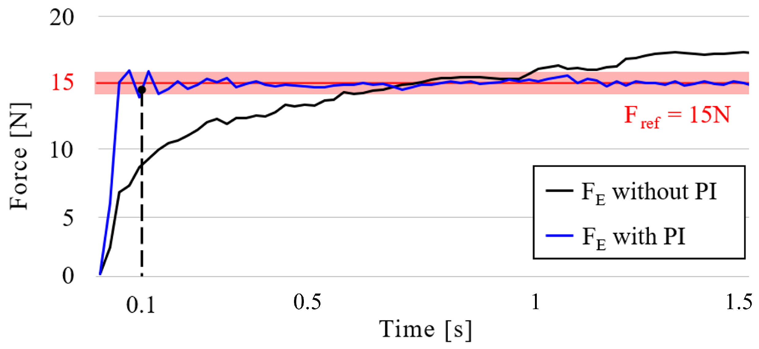
In the first case, without belt rotation, the force tracking ability between the SEA arm with and without PI control was measured. K P was set to 0.3 for both the SEA arm and the re-tensioner, while K I was set to 0.1 and 0.05 for the SEA arm and re-tensioner, respectively. Figure 13 shows the forces measured at contact point E with and without PI control. As shown in the figure, a settling time of 0.096 s is observed for the PI-applied SEA arm, following a 4% error range around the reference force of 15 N. However, owing to the overlapped belt joint, vigorous vibration was inevitable even with a drive wheel of 300 rpm. Accordingly, a simple moving average (SMA) filter was used for evaluation, as in Duong et al.’s work [] for a vibration sensor application using (10).
SMA = A 1 + A 2 + + A n n
where n is the window length and A i is the i-th sample of the measured force signal. Lotysh et al. [] and Zakamulin [] also expounded on the SMA and window or unit size effect.
Figure 13. Forces under no-belt-rotation with and without PI control. Red area marks the target control interval.
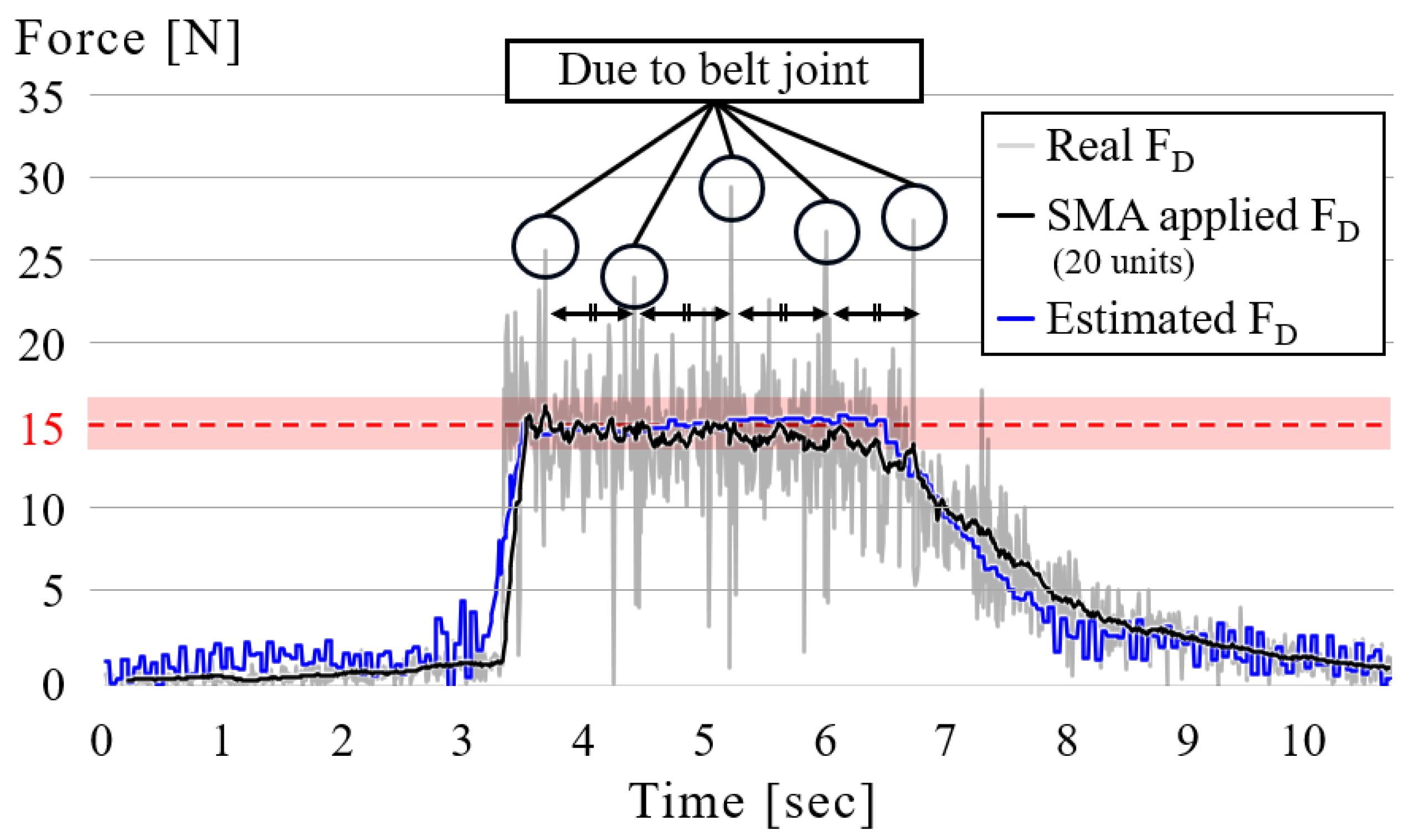
Figure 14 shows the force measured on contact point D with PI control and the SMA filter with 4% of the total number of samples—20 in this case—during belt operation. The belt joint generates equally spaced spikes in the force trace. To suppress this periodic component without distorting the low-frequency envelope, we use the simple moving average defined in Equation (10) with a window of n = 20 (4% of samples). All quantitative metrics (peak force and settling time) are computed from the unfiltered signals, the SMA curve is for visualization only and therefore does not bias those estimates. The robot approached the target surface with the belt rotating and then departed from it after 4%. The time gaps between the sudden jumps in the graph are constant, indicating that this is owing to the overlapping part of the belt. The gray part represents the data measured on the target surface with the load cells, while the black line represents the same data filtered via SMA. The blue area represents the force exerted by the SEA arm. In this study, PI control is used to validate the SEA arm and re-tensioner architecture under the reported operating conditions; detailed controller optimization and stability-margin analysis are left for future work.
Figure 14. Belt-operation force with SMA. Red area marks the target control interval.
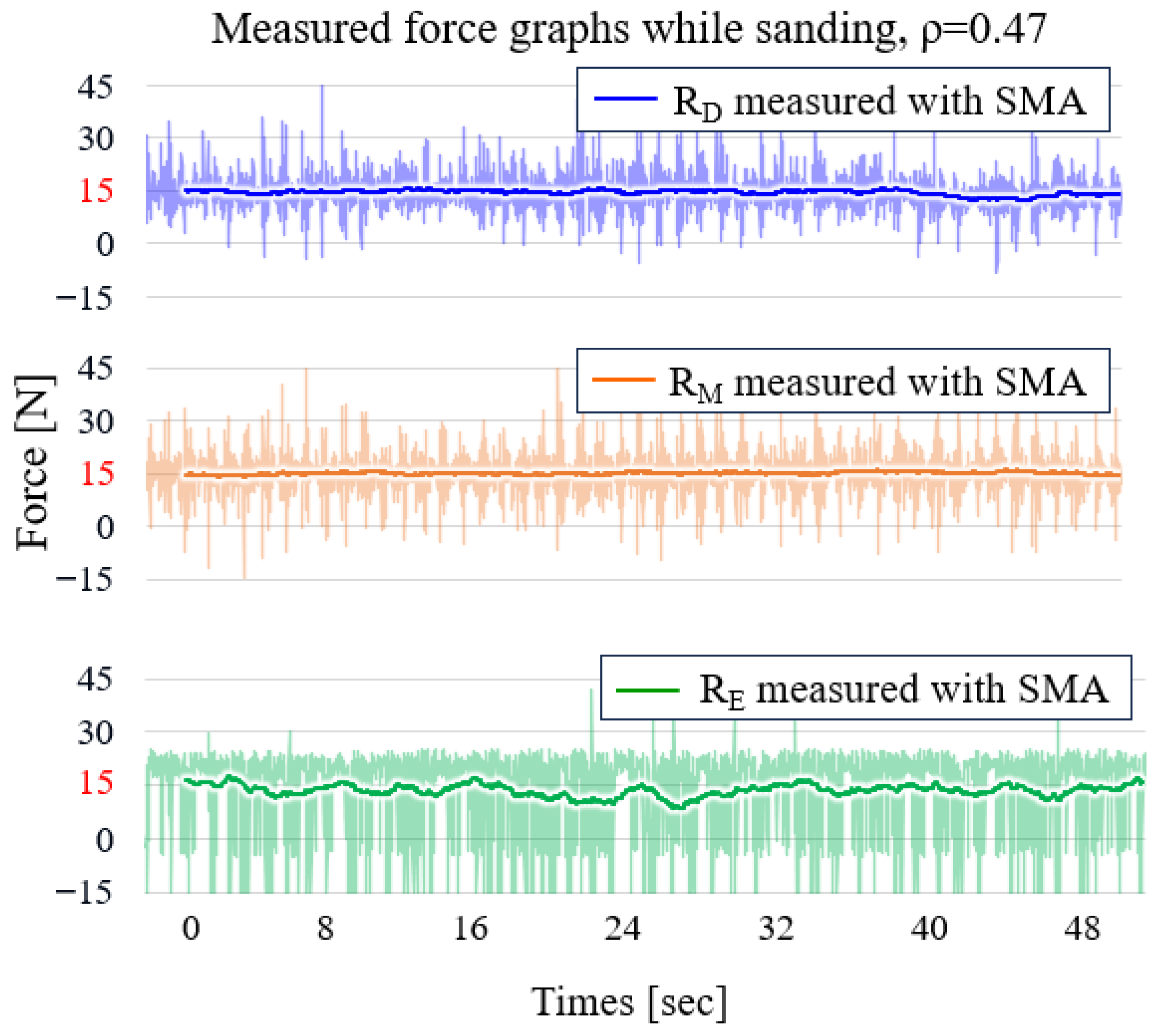
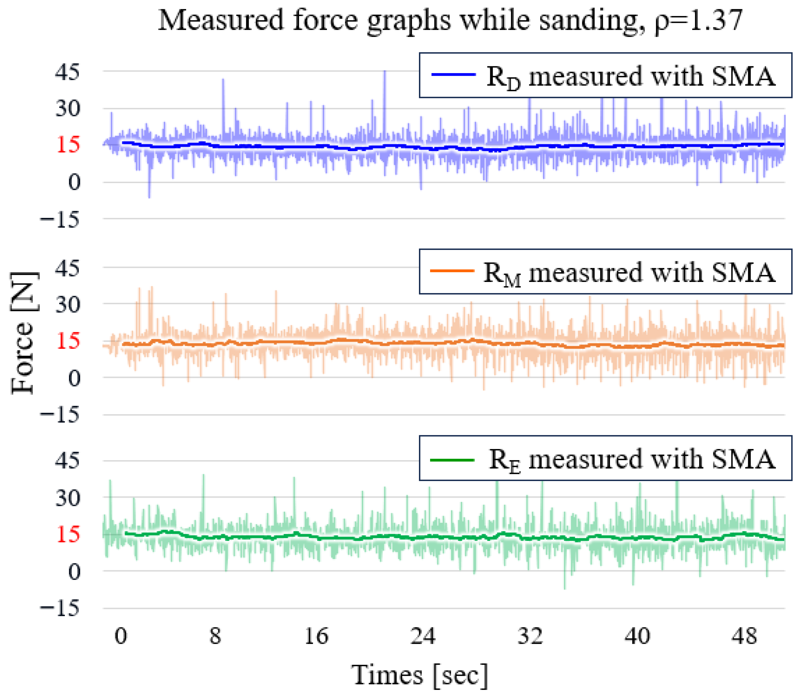
Figure 15 shows the reaction force measured on points D, M, and E on the target surface with a curvature of 0.47. Figure 16 shows the same but for a target surface with a curvature of 1.37 during the sanding operation, with the same SMA window size percentage as before. These figures show that the force-tracking ability of R D is superior to that of R E . This is because of the belt rotation direction. For the SEA arm at point D, the belt moves in the direction that extends the spring while compressing the spring on the SEA arm at point E. However, because extension springs are used in this mechanism, the belt cannot be further compressed, making the force-tracking ability of the SEA arm at point E slightly inferior to that at point D.
Figure 15. Forces at D, M, and E on the target with curvature 0.47 during the belt sanding operation. Thin lines indicate raw data and thick lines indicate SMA-filtered data.
Figure 16. Forces at D, M, and E on the target with curvature 1.37 during the belt sanding operation. Thin lines indicate raw data and thick lines indicate SMA-filtered data.
Table 3 consolidates the operating and evaluation conditions used for the force-tracking results reported in Figure 15 and Figure 16.
Table 3. Parameters used for force-tracking experiments.

4.3. Discussion

To verify the effectiveness of the proposed mechanism, the gaps in the maximum and minimum normal forces exerted on the plate during operation, as well as the finished quality evaluated with the vision system, were compared with those of a passive arm belt sanding robot in Figure 17, which was used in a previous study. That robot has fixed idler and passive arm positions and cannot calculate any specific force on the target surface or itself. This imaging pipeline, including its latency considerations, is consistent with real-time inspection modules [].
Figure 17. Previous passive robotic arm without a re-tensioner and SEA system.
Figure 18 illustrates the vision inspection concept and process. The plate was first colored with a white primer and then black to show the sanded area edge, as the sanded surface reflects light, making it difficult to distinguish between the untouched and sanded surfaces. The finished surface was moved into a black jig to take the pictures, which were processed as described in a previous study, but in opposite colors. White represents the sanded area and black represents the opposite.
Figure 18. Vision inspection concept: (a) test-bench for vision inspection; (b) vertical sanding process result; (c) image resized and processed into 320 × 640 pixels.
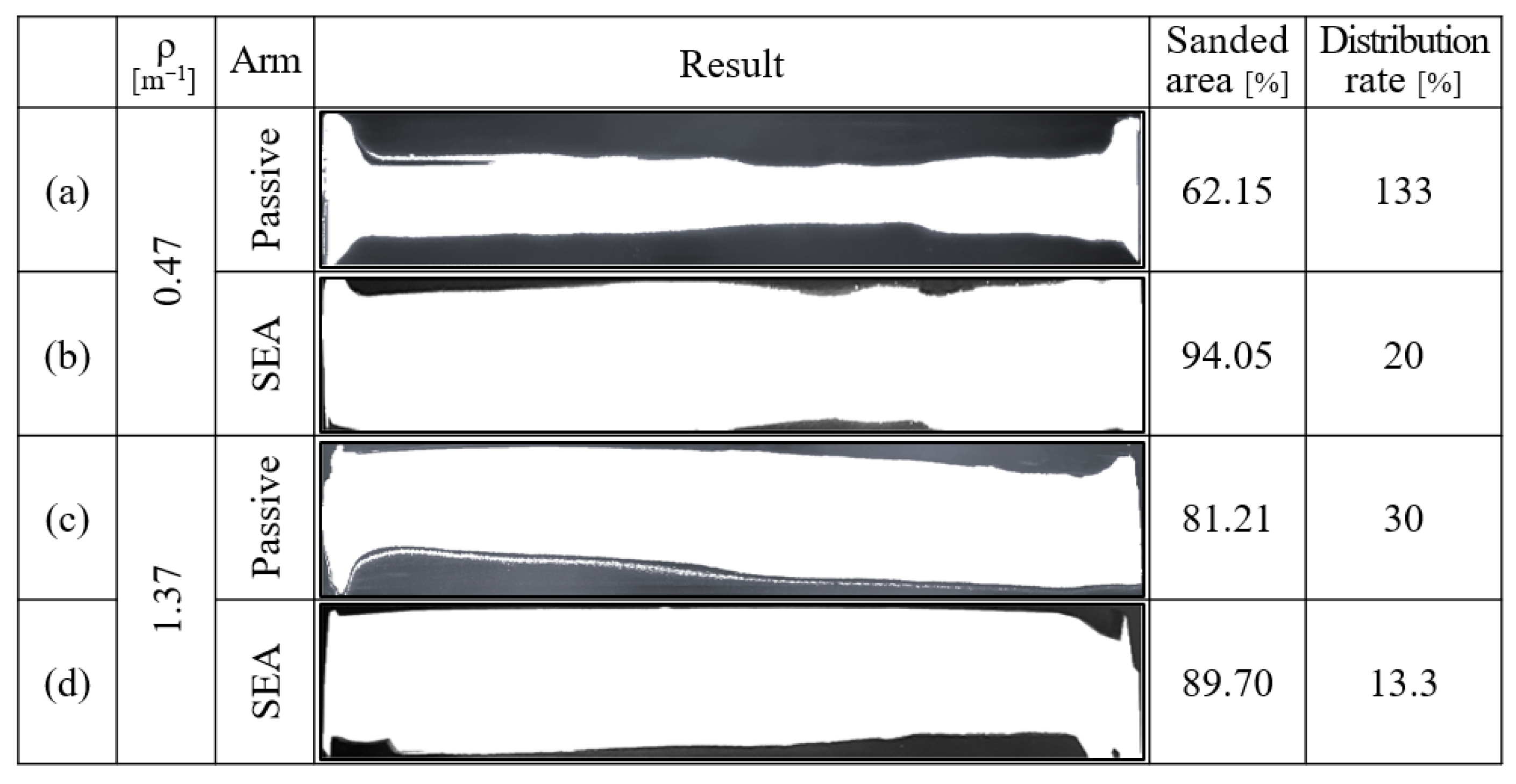
Figure 19 shows the vertical sanding process results with SEA and passive arms on each target surface. For the target surface with a curvature of 0.47, a 31.85% improvement in the sanded surface area was achieved, from 62.2% to 94.05%. For a target surface with a curvature of 1.37, an 8.49% improvement was achieved, from 81.21% to 89.7%.
Figure 19. Vertical sanding process results: (a) Curvature of 0.47 with passive arms; (b) curvature of 0.47 with SEA arms; (c) curvature of 1.37 with passive arms; and (d) curvature of 1.37 with SEA arms.
The distribution rate, defined as the gap between the maximum and minimum normal forces exerted on the target plate throughout the contact area divided by the maximum force, was no less than 20% when the SEA arms were used. However, without a re-tensioner on the passive arm robot, even though having the same normal force on points D and E as 15 N was possible, the force at point M was unpredictable, ranging from 10 to 5 N, because of the surface deformation caused by the high normal forces on D and E. This resulted in a distribution rate improvement of 113% and 16.7% for the 0.47- and 1.37-curvature target surfaces, respectively.
Under the operating conditions (belt width 50 mm and vertical feed 50 mm/min), the area rate for a single vertical pass is 0.05 m × 0.05 m / min = 0.0025 m 2 / min , i.e., 0.15 m 2 / h . Force uniformity across the contact follows the distribution rate results already reported for the two convex curvatures (0.47 and 1.37) under identical settings. A principal limitation observed in the experiments is the compression asymmetry of the extension spring at wheel E, which slightly degrades tracking when the belt drives the spring into compression. A practical mitigation within the present mechanism is to select an appropriate spring preload and to implement asymmetric force loop gains between D and E. Although the R A R M fit is validated by closed-loop performance within R A = 15 130 N , statistical uncertainty will be quantified in future work after increasing the number of repeated sweeps.
5. Conclusions

In this study, a novel robotic hardware capable of sanding large convex surfaces while in motion was proposed. To achieve this, SEA sanding arm and re-tensioner were designed. A specially designed rotary SEA was introduced to enhance robustness against noise and effectively absorb shocks during the sanding process. Additionally, using PI control, the robot simultaneously sanded a width of 1 m while in motion. To prove its performance, the estimated normal force value was compared with the measured value at the two main contact points on the target surface as well as at the midpoint of the contact area. Furthermore, a visual method was used to evaluate the evenness of the normal force applied to the target surface. It was experimentally confirmed that the proposed mechanism is effective in tracking forces and maintaining a well-dispersed force such that the sanded area is evenly distributed throughout the contact area compared to the previous passive-arm sanding robot, which was optimized using the Taguchi method.

Author Contributions

Conceptualization, T.K. and T.S.; methodology, H.J. and C.M.; validation, H.J. and C.M.; formal analysis, H.J. and T.K.; investigation, H.J.; writing—original draft preparation, H.J.; writing—review and editing, T.K. and T.S.; supervision, T.S.; funding acquisition, T.K. All authors have read and agreed to the published version of the manuscript.

Funding

This work was supported by the National Research Foundation of Korea (NRF) grant funded by the Korea government (MSIT) (RS-2025-00521072).

Data Availability Statement

Dataset available on request from the authors.

Conflicts of Interest

The authors declare no conflicts of interest.

References

  1. Zhang, X.; Cabaravdic, M.; Kneupner, K.; Kuhlenkoetter, B. Real-Time Simulation of Robot Controlled Belt Grinding Processes of Sculptured Surfaces. Int. J. Adv. Robot. Syst. 2004, 1, 12. [Google Scholar] [CrossRef]
  2. Song, Y.; Yang, H.; Lv, H. Intelligent Control for a Robot Belt Grinding System. IEEE Trans. Control Syst. Technol. 2013, 21, 716–724. [Google Scholar]
  3. Brecher, C.; Tuecks, R.; Zunke, R.; Wenzel, C. Development of a Force Controlled Orbital Polishing Head for Free Form Surface Finishing. Prod. Eng. 2010, 4, 269–277. [Google Scholar] [CrossRef]
  4. Ge, J.; Deng, Z.; Li, Z.; Li, W.; Lv, L.; Liu, T. Robot Welding Seam Online Grinding System Based on Laser Vision Guidance. Int. J. Adv. Manuf. Technol. 2021, 116, 1737–1749. [Google Scholar] [CrossRef]
  5. Nagata, F.; Kusumoto, Y.; Fujimoto, Y.; Watanabe, K. Robotic Sanding System for New Designed Furniture with Free-Formed Surface. Robot. Comput.-Integr. Manuf. 2007, 23, 371–379. [Google Scholar] [CrossRef]
  6. Iglesias, I.; Sebastián, M.A.; Ares, J.E. Overview of the State of Robotic Machining: Current Situation and Future Potential. Procedia Eng. 2015, 132, 911–917. [Google Scholar] [CrossRef]
  7. Jinno, M.; Ozaki, F.; Yoshimi, T.; Tatsuno, K.; Takahashi, M.; Kanda, M.; Tamada, Y.; Nagataki, S. Development of a Force Controlled Robot for Grinding, Chamfering and Polishing. In Proceedings of the 1995 IEEE International Conference on Robotics and Automation, Nagoya, Japan, 21–27 May 1995; Volume 2, pp. 1455–1460. [Google Scholar]
  8. Xu, X.; Chen, W.; Zhu, D.; Yan, S.; Ding, H. Hybrid Active/Passive Force Control Strategy for Grinding Marks Suppression and Profile Accuracy Enhancement in Robotic Belt Grinding of Turbine Blade. Robot. Comput.-Integr. Manuf. 2021, 67, 102047. [Google Scholar] [CrossRef]
  9. Chen, H.; Yang, Z.; Ding, H. Robotic Compliant Grinding of Curved Parts Based on a Designed Active Force-Controlled End-Effector with an Optimized Series Elastic Component. Robot. Comput.-Integr. Manuf. 2024, 86, 102646. [Google Scholar] [CrossRef]
  10. Li, D.; Yang, J.; Zhao, H.; Ding, H. Contact Force Plan and Control of Robotic Grinding Towards Accurate Material Removal on Complex Surfaces. Int. J. Mech. Sci. 2022, 227, 107449. [Google Scholar] [CrossRef]
  11. Min, K.; Ni, F.; Liu, H. Robotic Abrasive Belt Grinding of Complex Curved Blades Based on a Novel Force-Control Architecture Integrating Smooth Trajectories. J. Manuf. Process. 2023, 107, 447–458. [Google Scholar] [CrossRef]
  12. Wen, Y.; Jaeger, D.J.; Pagilla, P.R. Uniform Coverage Tool Path Generation for Robotic Surface Finishing of Curved Surfaces. IEEE Robot. Autom. Lett. 2022, 7, 4931–4938. [Google Scholar] [CrossRef]
  13. Kim, H.; Jin, H.; Lee, W.; Chae, S.; Kim, T.; Seo, T. Experimental Design of 4-Point Supported Belt Robot for Sanding Large Convex Surfaces. Sci. Rep. 2024, 14, 6861. [Google Scholar] [CrossRef]
  14. Lee, C.; Kwak, S.; Kwak, J.; Oh, S. Generalization of Series Elastic Actuator Configurations and Dynamic Behavior Comparison. Actuators 2017, 6, 26. [Google Scholar] [CrossRef]
  15. Wang, Y.-H.; Lo, Y.-C.; Lin, P.-C. A Normal Force Estimation Model for a Robotic Belt-Grinding System. In Proceedings of the 2020 IEEE/ASME International Conference on Advanced Intelligent Mechatronics (AIM), Boston, MA, USA, 6–9 July 2020; pp. 1922–1928. [Google Scholar]
  16. Siciliano, B.; Sciavicco, L.; Villani, L.; Oriolo, G. Robotics: Modelling, Planning and Control; Springer: New York, NY, USA, 2009. [Google Scholar]
  17. Hogan, N. Impedance Control: An Approach to Manipulation. ASME J. Dyn. Syst. Meas. Control 1985, 107, 1–7. [Google Scholar] [CrossRef]
  18. Åström, K.J.; Hägglund, T. PID Controllers: Theory, Design, and Tuning; ISA: Research Triangle Park, NC, USA, 1995. [Google Scholar]
  19. Seborg, D.E.; Edgar, T.F.; Mellichamp, D.A. Process Dynamics and Control; John Wiley & Sons: Hoboken, NJ, USA, 2003. [Google Scholar]
  20. Horvath, M.; Kundrak, J.; Mamalis, A.G.; Gyani, K. On the Precision Grinding of Advanced Ceramics. Int. J. Adv. Manuf. Technol. 2002, 20, 255–258. [Google Scholar] [CrossRef]
  21. Bergesen, H.O.; Parmann, G.; Thommessen, Ø.B. European Agreement Concerning the International Carriage of Dangerous Goods by Road (ADR). In Yearbook of International Cooperation on Environment and Development 1998–99; Routledge: London, UK, 2018; pp. 94–95. [Google Scholar]
  22. Duong, T.T.; Nguyen, B.H.Q.; Maneetien, N. Implementation of Moving Average Filter on STM32F4 for Vibration Sensor Application. In Proceedings of the 2018 4th International Conference on Green Technology and Sustainable Development (GTSD), Ho Chi Minh City, Vietnam, 23–24 November 2018; pp. 627–631. [Google Scholar]
  23. Lotysh, V.; Gumeniuk, L.; Humeniuk, P. Comparison of the Effectiveness of Time Series Analysis Methods: SMA, WMA, EMA, EWMA, and Kalman Filter for Data Analysis. Inform. Autom. Pomiary Gospod. Ochr. Środowiska 2023, 13, 71–74. [Google Scholar] [CrossRef]
  24. Zakamulin, V. Moving Averages for Market Timing. SSRN 2016, 1–19. [Google Scholar] [CrossRef]
  25. Hoshino, Y.; Shimasaki, M.; Rathnayake, N.; Dang, T.L. Performance verification and latency time evaluation of hardware image processing module for appearance inspection systems using FPGA. J. Real-Time Image Process. 2024, 21, 20. [Google Scholar] [CrossRef]
Disclaimer/Publisher’s Note: The statements, opinions and data contained in all publications are solely those of the individual author(s) and contributor(s) and not of MDPI and/or the editor(s). MDPI and/or the editor(s) disclaim responsibility for any injury to people or property resulting from any ideas, methods, instructions or products referred to in the content.

Article Metrics

Citations

Article Access Statistics

Multiple requests from the same IP address are counted as one view.