Article

Performance Analysis of Nonlinear Stiffness Suspension Based on Multi-Objective Optimization

1
School of Computer Engineering, Jiangsu University of Technology, Changzhou 213001, China
2
School of Automotive and Traffic Engineering, Jiangsu University, Zhenjiang 212013, China
3
Automotive Engineering Research Institute, Jiangsu University, Zhenjiang 212013, China
*
Author to whom correspondence should be addressed.
Machines 2025, 13(11), 1011; https://doi.org/10.3390/machines13111011
Submission received: 13 October 2025 / Revised: 30 October 2025 / Accepted: 30 October 2025 / Published: 2 November 2025
(This article belongs to the Special Issue New Journeys in Vehicle System Dynamics and Control)

Abstract

This study optimizes vehicle suspension dynamics by introducing a controllable degree of nonlinearity, characterized by a parameter ε, into the spring element of Inerter-Spring-Damper (ISD) systems. Quarter-vehicle models for parallel and series ISD configurations are established, and a multi-objective genetic algorithm optimizes the parameters under random road excitation to minimize body acceleration (BA), suspension working space (SWS), and dynamic tire load (DTL). Results demonstrate that optimizing ε brings advantages: compared to a conventional passive suspension, the optimized parallel ISD suspension reduces BA, SWS, and DTL by 7.98%, 8.57%, and 1.69%, respectively, with the BA reduction notably improving from 5.94% (achieved by the linear ISD with ε = 0) to 7.98%. Similarly, the optimized series ISD achieves reductions of 2.53%, 7.62%, and 6.42% in BA, SWS, and DTL, showing a more balanced enhancement over its linear counterpart. The analysis reveals how ε distinctly influences the performance trade-offs, validating that strategically tuning the spring nonlinearity degree, in synergy with the inerter and damper, provides an effective method for superior suspension performance customization.

1. Introduction

The suspension system is a critical component that connects the vehicle body to the wheels, and its performance directly determines ride comfort, handling stability, and driving safety. The pursuit of superior suspension performance has driven innovations across various vehicle types. For mainstream vehicle suspension systems, the limitations of traditional passive suspensions [1] with fixed parameters have spurred the development of semi-active [2] and active [3] suspensions. Despite their enhanced performance, issues such as high costs and energy consumption persist. Smith introduced the inerter, a new element for vibration isolation [4]. Due to the tremendous success of the inerter in Formula 1 racing, new mechanical vibration isolation networks composed of ISDs have been widely applied in the field of mechanical vibration isolation. Generally, inertial elements have been successfully applied across various interdisciplinary domains, including automotive engineering [5,6,7,8], civil engineering [9,10], aerospace engineering [11], and ocean engineering [12].
In the structural design of ISD suspensions, Du et al. adopted an analytical method to enumerate 21 types of ISD suspension structures, selected 9 typical ISD suspension structures, and obtained 5 ISD suspension structures with good vibration reduction performance and simple structure through simulation [13]. Shen et al. proposed a positive real synthesis design method for ISD suspensions based on fractional order, taking the biquadratic transfer function as the research object to design the equivalent network structure of fractional order components [14]. Control strategy design includes sliding mode control [15,16,17,18], fuzzy control [19,20,21,22], etc., and these methods have been widely applied in suspension systems. Shen et al. proposed a fractional-order sliding mode control to adjust the output force through ISD suspension, which shows excellent vibration suppression performance [23]. Jin et al. proposed a semi-active ISD suspension control strategy based on improved fuzzy neural network PID control, which improves the ride comfort and handling stability of vehicles [24]. Zhang et al. proposed a model-free adaptive control based on genetic algorithm, which effectively improves the vehicle dynamic performance [25]. The functional scope of ISD suspensions is also expanding beyond mere vibration isolation, for instance, through integration with energy-harvesting technologies, revealing intrinsic trade-offs between ride comfort and energy-harvesting efficiency across different ISD structures [26].
However, despite these significant and promising advancements across methodological, functional, and control dimensions, a critical and ubiquitous physical characteristic remains largely unexplored within the ISD framework: the intrinsic nonlinearity of the suspension spring itself. Current research has considered the nonlinear characteristics of springs. Zhu et al. studied the nonlinear dynamic characteristics of a vehicle semi-active suspension system with SMA spring, developed the nonlinear dynamic model based on hysteretic nonlinear theory, and analyzed the stability and bifurcation characteristics of the suspension system [27]. Huang et al. proposed adaptive control designs for vehicle active suspension systems with unknown nonlinear dynamics (e.g., nonlinear spring and piece-wise linear damper dynamics), using an augmented neural network to compensate for the unknown nonlinearities and a novel adaptive law to estimate both NN weights and uncertain model parameters, improving control performance and simplifying parameter tuning [28]. Lauß et al. proposed a parameter identification approach formulated as an optimization task to quantify the nonlinear spring and damper characteristics of motorcycle suspension modifications, using efficient gradient computation with the adjoint variable approach and cubic splines to minimize the deviation between simulation and measurement [29]. Zhao et al. analyzed the performance of suspensions with nonlinear springs, and the results show that the variation in nonlinear springs has a significant impact on suspension performance [30]. Current research primarily focuses on structural design and linear spring analysis, neglecting the nonlinearity of suspension springs. Considering the hypothesis that the interaction between nonlinear springs, inerters, and dampers might lead to unprecedented changes in vehicle dynamic performance, it seems necessary to reveal the underlying correlations.
This paper aims to analyze the dynamic performance of ISD suspensions with both linear and nonlinear suspension springs and to explore the influence of spring nonlinearity on suspension dynamic performance. The structure of the paper is organized as follows.
In Section 2, a quarter-vehicle model of a four-element ISD suspension considering nonlinear springs is established. Section 3 details the multi-objective optimization under random road input conditions using a genetic algorithm. Section 4 presents a simulation analysis of the dynamic performance of the proposed vehicle ISD suspension. Section 5 discusses the influence of spring nonlinearity on body acceleration, suspension dynamic deflection, and tire dynamic load. Finally, conclusions are drawn.

2. Model Formulation of Suspension Systems

2.1. Parallel Linear ISD Suspension Model

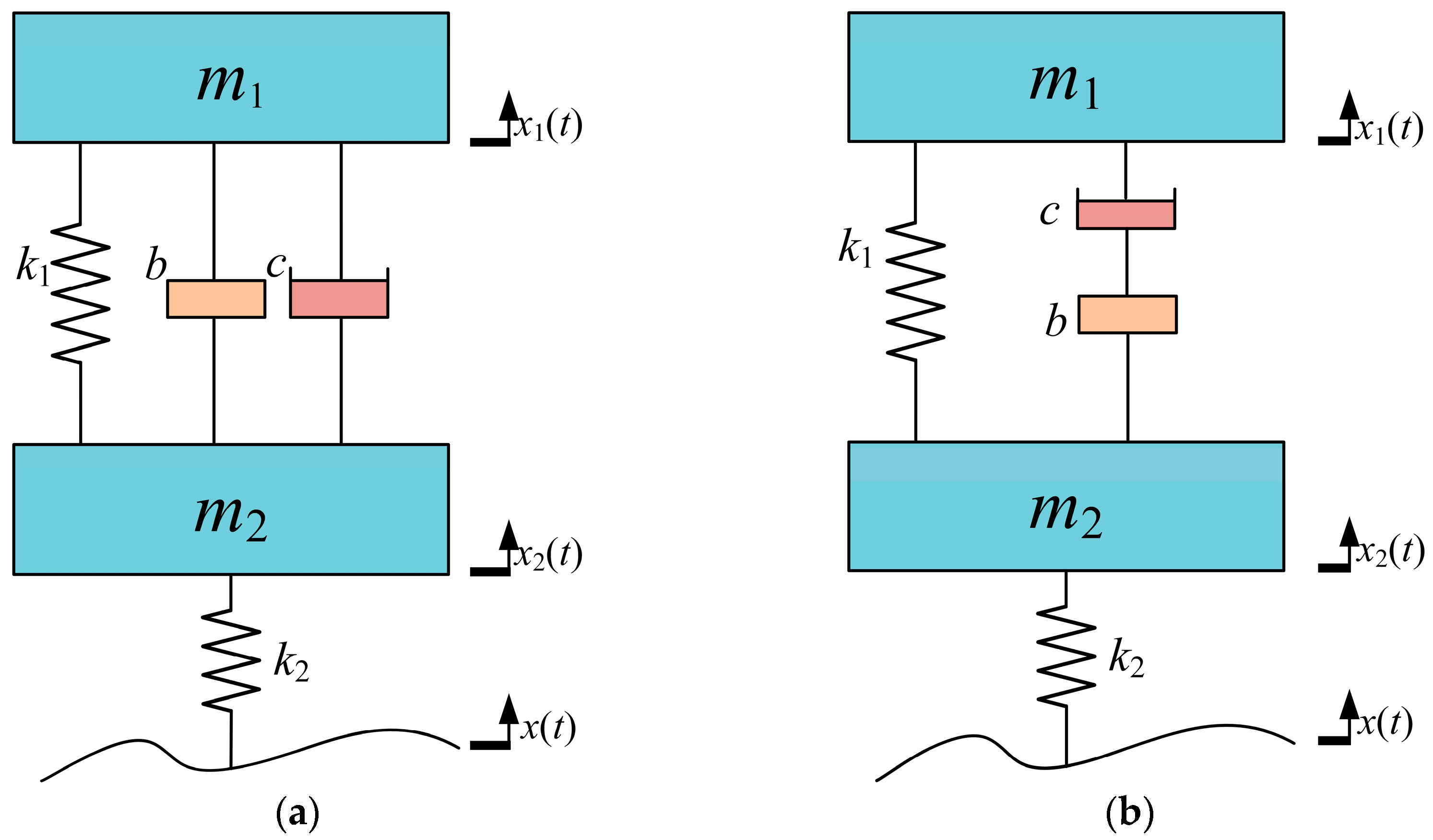
The quarter-vehicle model effectively illustrates the relative motion between the sprung mass and unsprung mass. Vehicle suspension systems employing inerter, spring, and damper elements exhibit diverse configurations. This study first examines a passive ISD suspension with a three-element parallel configuration comprising the suspension spring, inerter, and damper. Figure 1a shows the model of a 1/4 parallel linear vehicle ISD system.
In Figure 1, m1 is sprung mass, m2 is unsprung mass, k1 is suspension stiffness coefficient, c is damping coefficient, b is inertance coefficient, and k2 is tire stiffness. x1, x2, and x are vertical displacements of the sprung mass, unsprung mass, and road input, respectively.
Figure 1a shows the model of a 1/4 passive parallel vehicle suspension system. Traditional suspensions employ linear springs with constant stiffness. The force displacement relationship of a constant-stiffness spring is given by the following equation:
F s = k x
where Fs is spring force, k is spring stiffness, and x is spring displacement.
Combining Equation (1) and applying Newton’s second law of motion, the governing differential equations of motion for the parallel suspension 2-DOF quarter-vehicle model are derived as follows:
m 1 x ¨ 1 + k 1 x 1 x 2 + c x ˙ 1 x ˙ 2 + b x ¨ 1 x ¨ 2 = 0 m 2 x ¨ 2 k 1 x 1 x 2 c x ˙ 1 x ˙ 2 b x ¨ 1 x ¨ 2 + k 2 x 2 x = 0

2.2. Series Linear ISD Suspension Model

The passive ISD suspension configuration with the inerter and damper arranged in series, while the suspension spring is connected in parallel with the damper, is studied. Figure 1b shows the model of the 1/4 series linear vehicle ISD system.
The Laplace transform of its dynamic equation is as follows:
m 1 s 2 X 1 + k 1 X 1 X 2 + s T s X 1 X 2 = 0 m 2 s 2 X 2 + k 2 X 2 X k 1 X 1 X 2 s T s X 1 X 2 = 0
where X1, X2, and X are the Laplace transform forms of x1, x2, and x, respectively.
The expression of the velocity-type impedance T(s) is as follows:
T s = b s c b s + c

2.3. Suspension Model Considering Spring Nonlinearity

In practical suspension systems, springs often exhibit nonlinear force displacement characteristics, especially under large deformations. This nonlinear stiffness is a critical factor influencing ride comfort and handling stability. To quantitatively analyze this effect, a parametric model is introduced where the spring force is defined by a variable stiffness relationship characterized by a nonlinearity parameter ε. The force displacement relationship can be expressed as follows [31]:
F s = k x + ε k 3 x 3
where ε is a small parameter ranging over (0, 1), representing the degree of spring nonlinearity. When ε = 0, the spring is linear. k denotes the linear stiffness (unit: N/m), and k3 represents the cubic stiffness coefficient (unit: N·m−3), which characterizes the intensity of the cubic nonlinearity.
Consequently, for the nonlinear parallel suspension quarter-vehicle model,
m 1 x ¨ 1 + k 1 x 1 x 2 + ε k 3 x 1 x 2 3 + c x ˙ 1 x ˙ 2 + b x ¨ 1 x ¨ 2 = 0 m 2 x ¨ 2 k 1 x 1 x 2 ε k 3 x 1 x 2 3 c x ˙ 1 x ˙ 2 b x ¨ 1 x ¨ 2 + k 2 x 2 x = 0
For the nonlinear series suspension quarter-vehicle model,
m 1 s 2 X 1 + k 1 X 1 X 2 + ε k 3 X 1 X 2 3 + s T s X 1 X 2 = 0 m 2 s 2 X 2 + k 2 X 2 X k 1 X 1 X 2 ε k 3 X 1 X 2 3 s T s X 1 X 2 = 0

3. Optimization of Suspension Parameters

3.1. Multi-Objective Optimization for Linear Springs Using Genetic Algorithm

According to the fitting expression for road surface power spectral density specified in GB/T 7031-2005 [32] ‘Mechanical Vibration—Road Surface Profiles—Reporting of Measured Data’, this study employs a first-order filtered band-limited white noise method to establish the random road excitation model:
q ˙ t = 2 π f 0 q t + 2 π G n 0 v w t
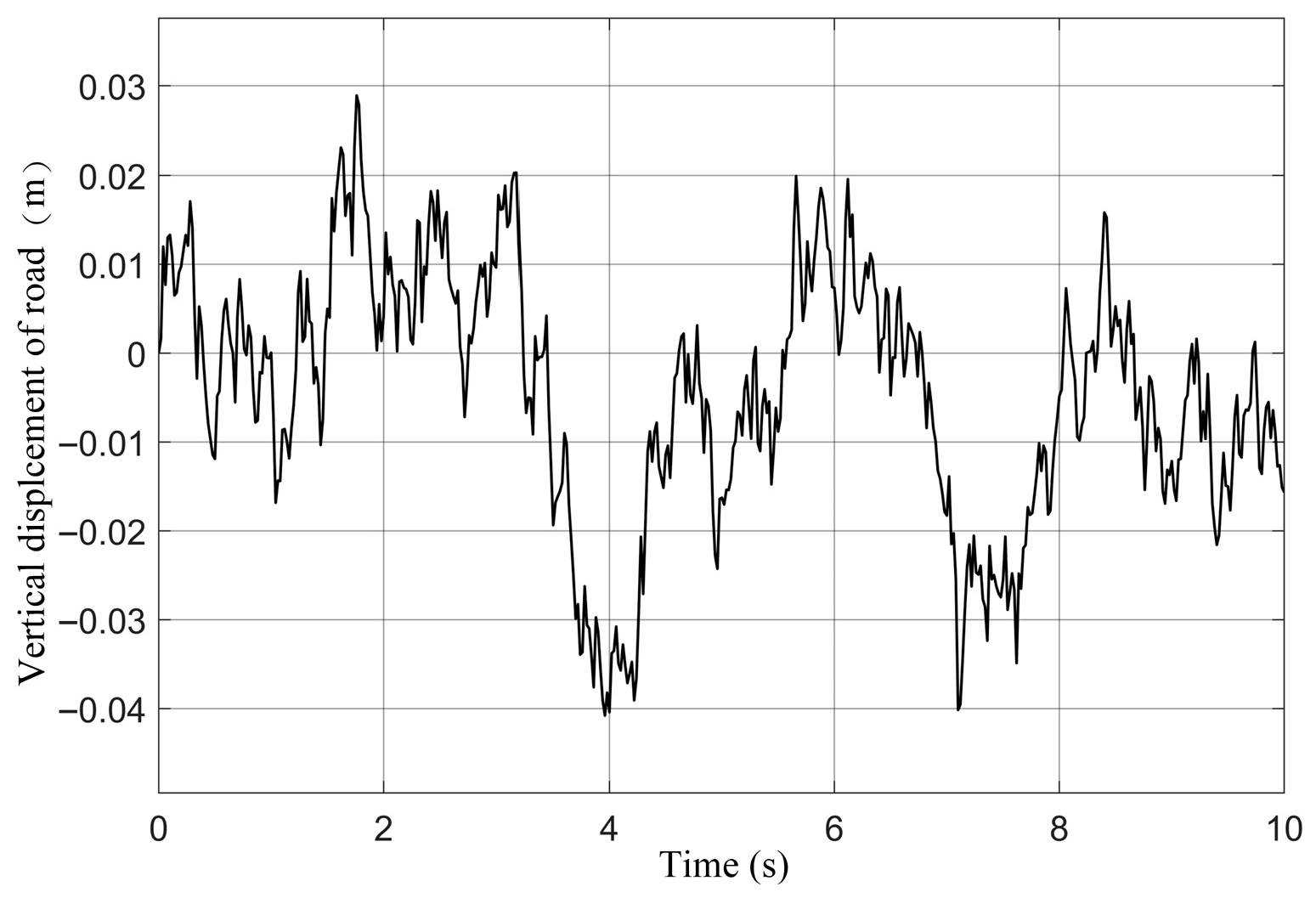
where f0 is lower cutoff frequency, q(t) is random road excitation signal, and G(n0) is road roughness coefficient. For the simulated Class C road: G(n0) = 2.56 × 10⁻⁵ m3·cycle−1, and v is vehicle speed (simulation value: 20 m/s). w(t) is gaussian white noise signal with zero mean. Figure 2 shows the road input displacement.
Model parameters are selected from a passenger vehicle. Table 1 presents relevant parameters of the vehicle’s passive suspension model [33].
Under Class C random road input at 20 m/s, the RMS values for the conventional passive suspension are as follows: BApass is 1.1868 m·s−2, SWSpass is 0.0105 m, DTLpass is 888 N.
The suspension stiffness k1, inertance coefficient b, and damping coefficient c of the suspension are selected as optimization variables, with respective ranges of (0–30,000) N m−1, (0–300) kg, and (0–3000) N s m−1. Optimization is performed separately for parallel and series suspension configurations. But the parameters for the multi-objective genetic algorithm are same: population size = 60, crossover probability = 0.8, mutation probability = 0.2, and number of iterations = 20.
To enhance vehicle ride comfort (meeting vibration isolation requirements) while reducing the probability of wheel lift-off and suspension bottoming-out, the optimization objectives are defined as BA, SWS, and DTL.
Variable boundary conditions are listed in Table 2. The objective functions are formulated as follows:
J 1 = ω 1 B A R M S B A p a s s + ω 2 S W S R M S S W S p a s s J 2 = D T L R M S D T L p a s s l b 1 b u b 1 l b 2 c u b 2 l b 3 k 1 u b 3
where J1 is comprehensive evaluation index for ride comfort and smoothness. J2 is wheel grounding capability, critically impacting vehicle driving stability. BA_RMS, SWS_RMS, DTL_RMS, are RMS values of the suspension. A penalty-augmented composite objective is constructed as follows:
J = ω 1 J 1 + ω 2 J 2 + p u n i s h m e n t
In Equation (10), the penalty rule is defined as follows: if any RMS value (BA, SWS, DTL) of the optimized suspension is worse than the conventional passive counterpart, a penalty term p = 100 is applied.
Weight coefficients w1 and w2 are set to 0.6 and 0.4, respectively, prioritizing passenger-oriented comfort in this study.

3.2. Multi-Objective Optimization for Nonlinear Springs Using Genetic Algorithm

For the nonlinear spring ISD suspension, four variables are designated as optimization parameters: k1, b, c, and ε, k3. The optimization range for ε is (0–1), while the lower bounds lbi and upper bounds ubi for k1, b, k3, and c remain identical to Equation (11). Variable boundary conditions are listed in Table 2. Optimization is performed separately for both parallel suspension configuration and series suspension configuration. The objective functions remain identical to those defined in Section 3.1. The optimization, however, is conducted over the augmented set of design variables, which incorporates the nonlinearity parameter ε bounded in the interval (0, 1):
l b 1 b u b 1 l b 2 c u b 2 l b 3 k 1 u b 3 l b 4 ε u b 4 l b 5 k 3 u b 5

4. Performance Analysis

4.1. Optimized Parameters

To demonstrate the dynamic performance of the optimized ISD suspension under random road excitation, simulations are conducted on a Class C road at 20 m/s. Table 3 lists the optimal parameters for each configuration.

4.2. Optimized RMS Values

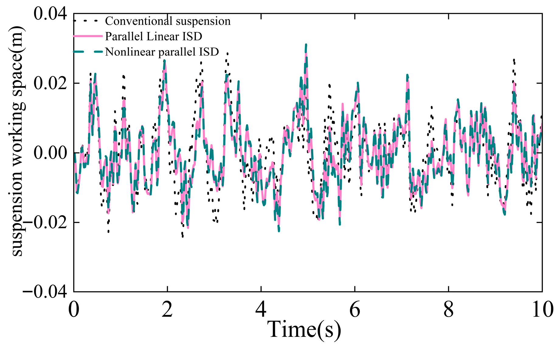
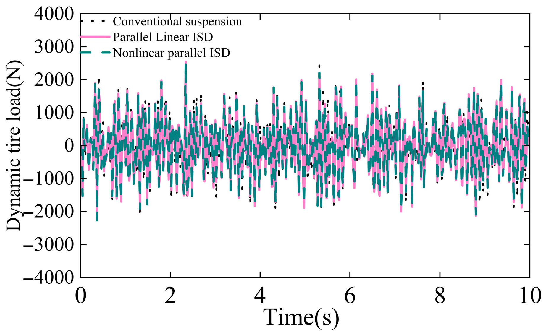
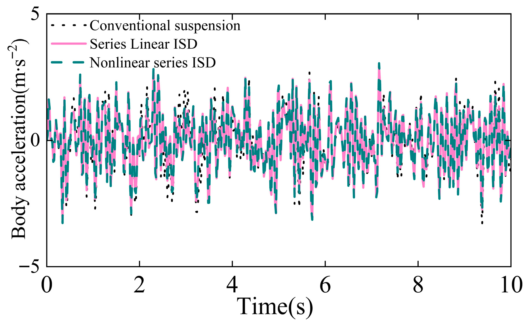
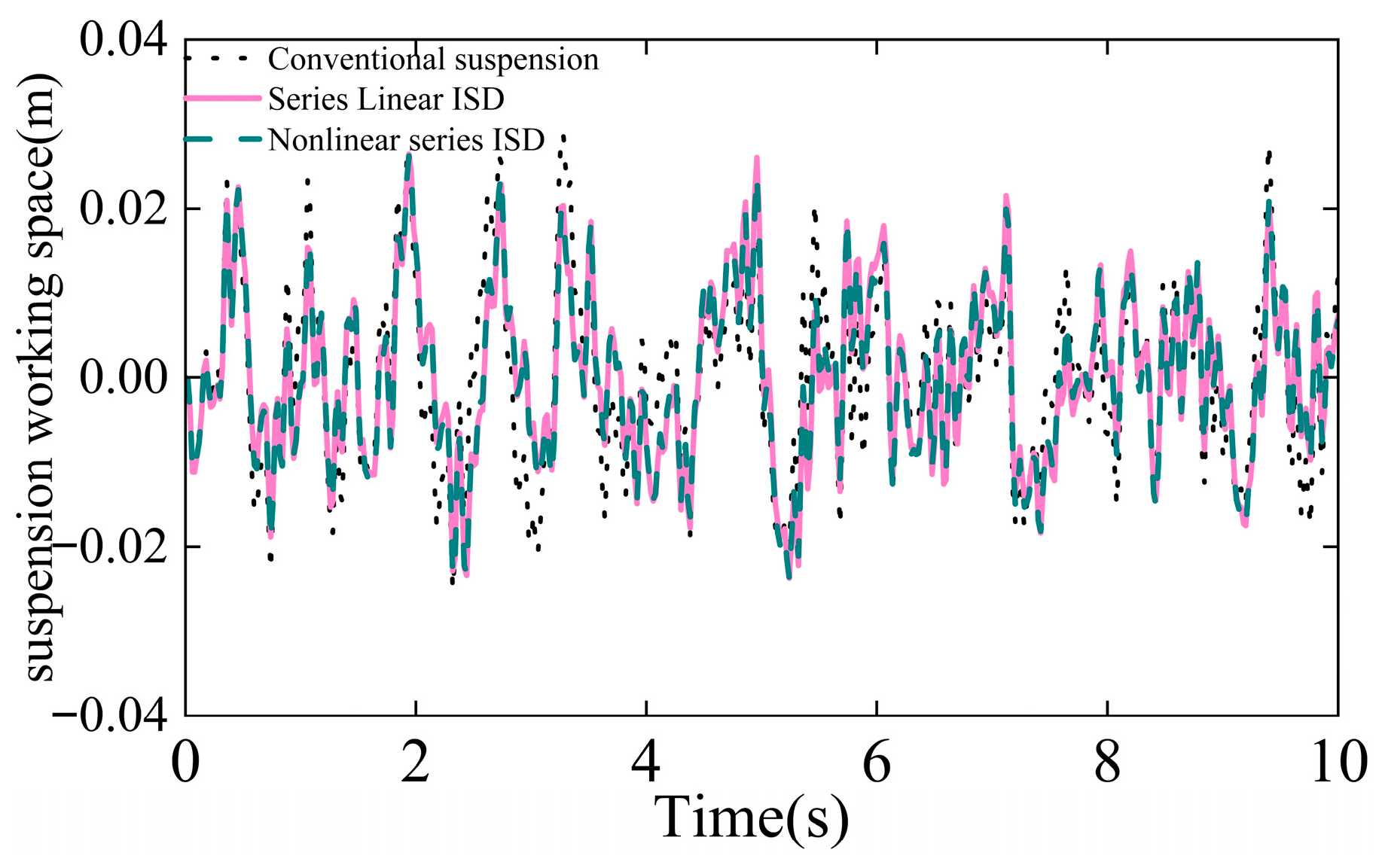
The RMS values of BA, SWS, and DTL for the parallel suspension comparing passive, linear-optimized, and nonlinear-optimized cases are shown in Table 4. This paper reuses the optimized parameters to perform time-domain simulations. Results of the parallel suspension are presented in Figure 3, Figure 4 and Figure 5. Similarly, RMS values for the series suspension comparing passive, linear-optimized, and nonlinear-optimized cases are summarized in Table 5. Results of the series suspension are presented in Figure 6, Figure 7 and Figure 8.
NameConventional SuspensionSeries Linear ISDDecreaseNonlinear Series ISDDecrease
RMS of body acceleration (m·s−2)1.18681.13604.28%1.15682.53%
RMS of suspension working space (m)0.01050.00986.67%0.00977.62%
RMS of dynamic tire load (N)8888425.18%8316.42%
Compared to the conventional passive suspension, all dynamic performance indices exhibit significant reductions. For the parallel suspension with linear springs, RMS values of BA, SWS, and DTL decrease by 5.94%, 10.48%, and 0.9%, respectively. With nonlinear springs, these indices decrease by 7.98%, 8.57%, and 1.69%, respectively. For the series suspension with linear springs, RMS values of BA, SWS, and DTL decrease by 4.28%, 6.67%, and 5.18%, respectively. With nonlinear springs, these indices decrease by 2.53%, 7.62%, and 6.42%, respectively. For the series suspension, the optimal ε = 0.07, although the BA shows a slight increase (1.1568 m·s−2) compared to the linear ISD suspension (1.1360 m·s−2); this represents a deliberate trade-off to achieve more substantial reductions in SWS and DTL.
The time-domain responses visually corroborate these improvements. Figure 3 and Figure 6 show that both linear and nonlinear ISD suspensions effectively attenuate body acceleration compared to the passive baseline. Figure 4 and Figure 7 demonstrate improved control over suspension working space, with the nonlinear parallel ISD exhibiting the smallest deflection. Furthermore, Figure 5 and Figure 8 confirm enhanced dynamic tire load management, particularly for the nonlinear parallel ISD configuration.

4.3. Simulation in the Frequency Domain

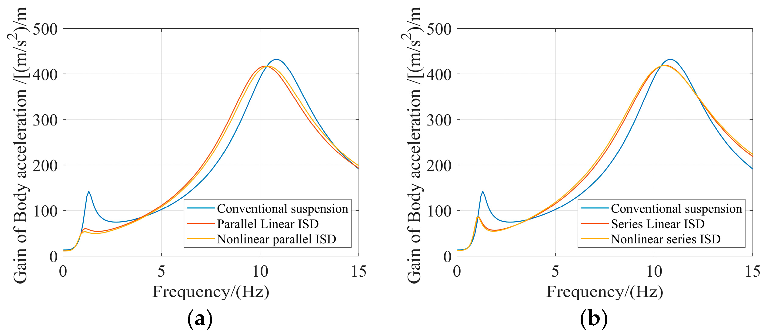
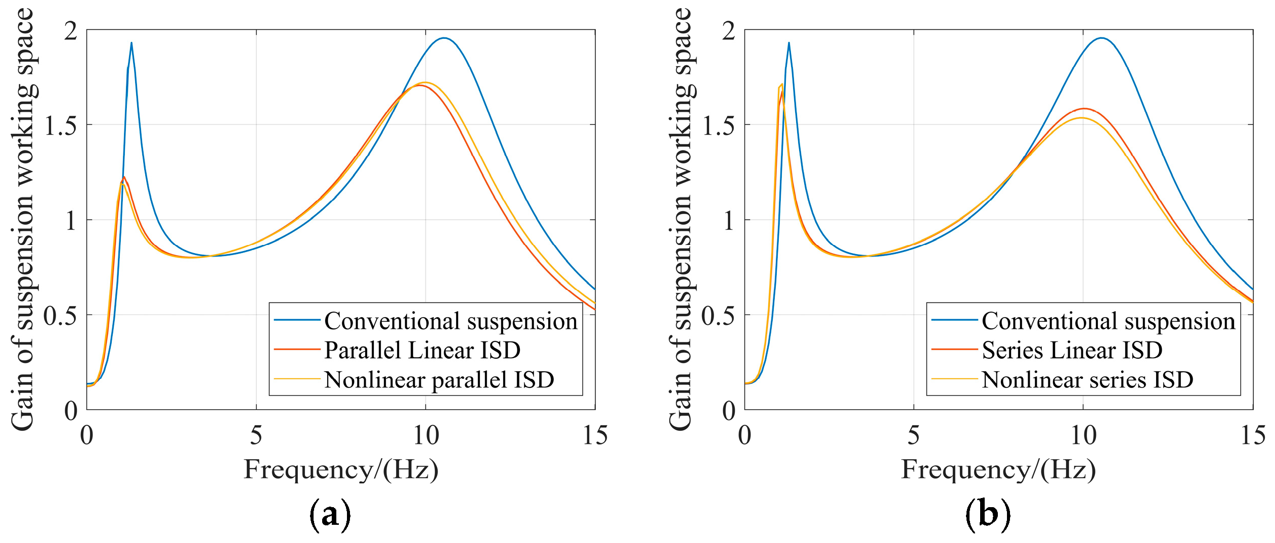
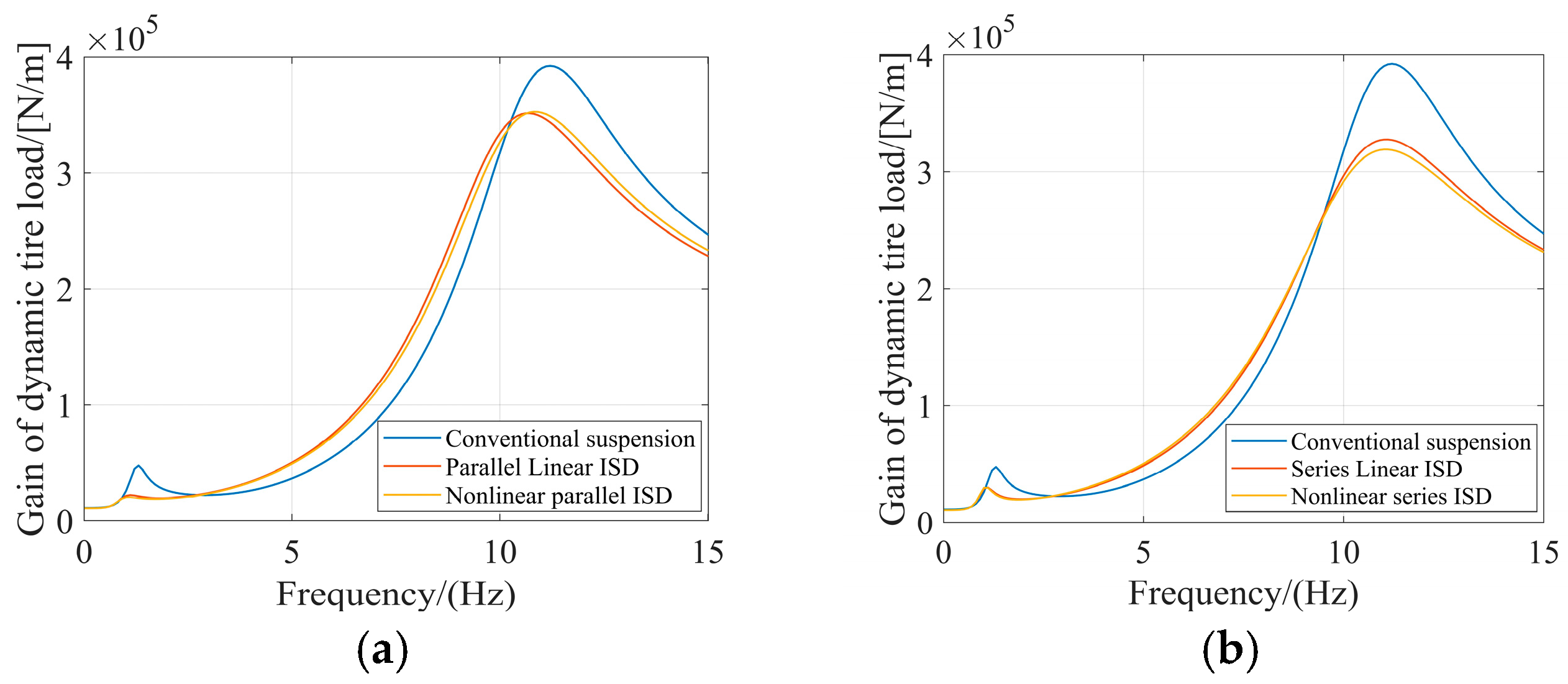
To further evaluate the vibration isolation performance under periodic excitations, frequency-domain simulations were conducted using sinusoidal inputs. Figure 9, Figure 10 and Figure 11 compare the frequency responses of BA, SWS, and DTL for the conventional passive suspension, linear ISD suspension (ε = 0), and nonlinear ISD suspension with optimized ε.
The conventional passive suspension exhibits pronounced resonance peaks across the evaluated frequency spectrum. In contrast, the incorporation of the inerter in both linear ISD configurations demonstrates a clear advantage in resonance control, effectively suppressing these critical resonance peaks compared to the passive baseline.
The introduction of optimized spring nonlinearity further enhances performance in specific configurations. For the parallel ISD suspension, the nonlinear design provides additional resonance suppression at identified critical frequencies. The nonlinear parallel ISD achieves improved control of BA at resonance frequencies of 1.11 Hz and 10.31 Hz, demonstrates better SWS performance at 1.11 Hz and 10.01 Hz, and shows the most substantial improvement in DTL control at 1.11 Hz and 10.91 Hz, significantly enhancing wheel ground contact stability.
For the series configuration, the nonlinear ISD suspension exhibits resonance frequencies at 1.11 Hz and 10.51 Hz for BA, 1.11 Hz and 10.01 Hz for SWS, and 1.01 Hz and 11.01 Hz for DTL. However, the performance improvement compared to the linear series ISD is minimal, with response curves showing considerable overlap at these resonance frequencies. This indicates that the linear series design already provides effective vibration isolation without requiring additional nonlinearity.
In summary, while both linear ISD configurations provide significant resonance suppression advantages over the conventional passive suspension, the benefits of spring nonlinearity are configuration-dependent. The parallel ISD suspension achieves meaningful performance gains through optimized nonlinearity, particularly in DTL control, whereas the series ISD configuration obtains sufficient performance from the linear design alone.

5. Analysis of Nonlinearity Degree Influence

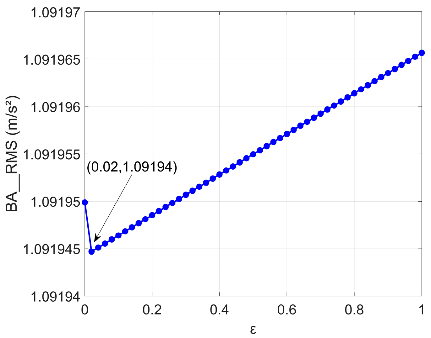
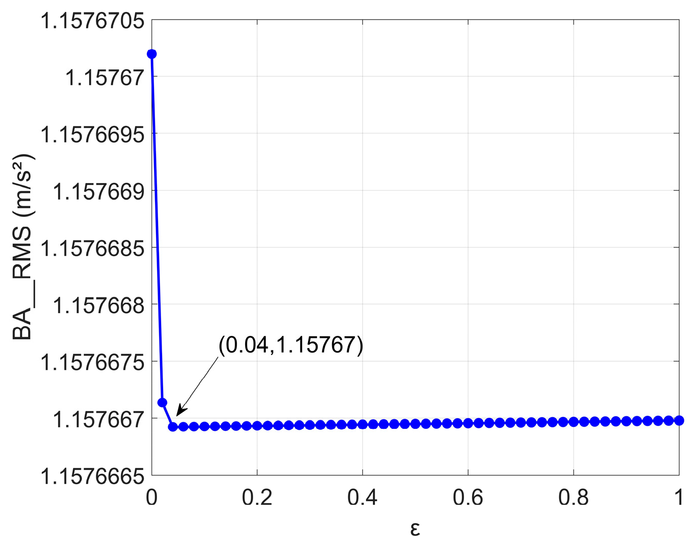
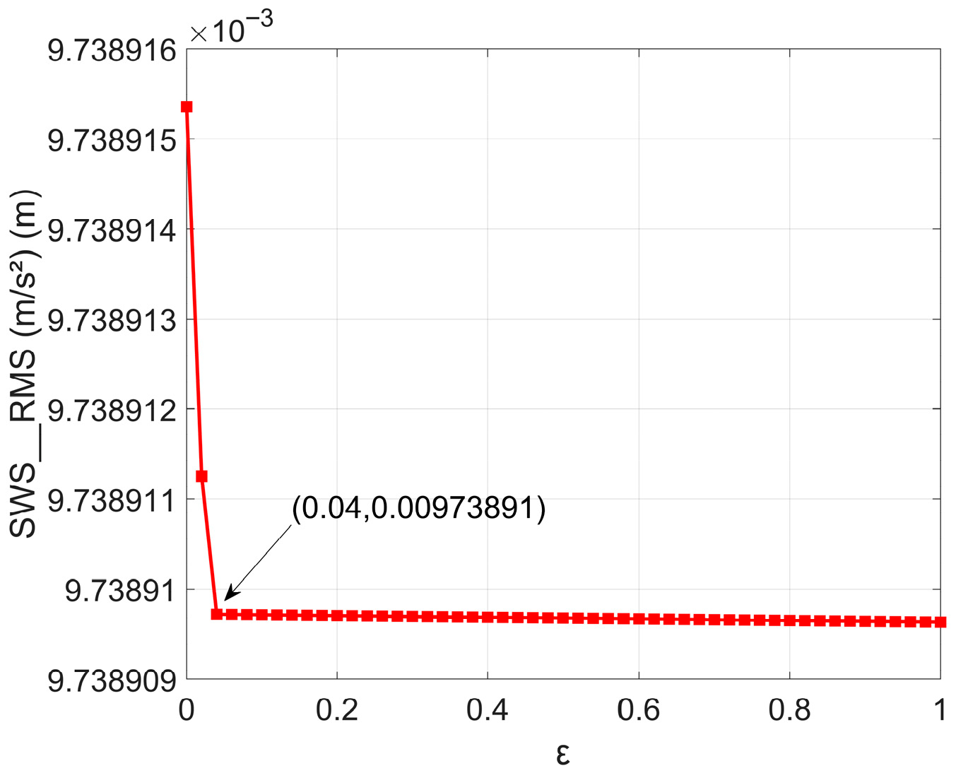
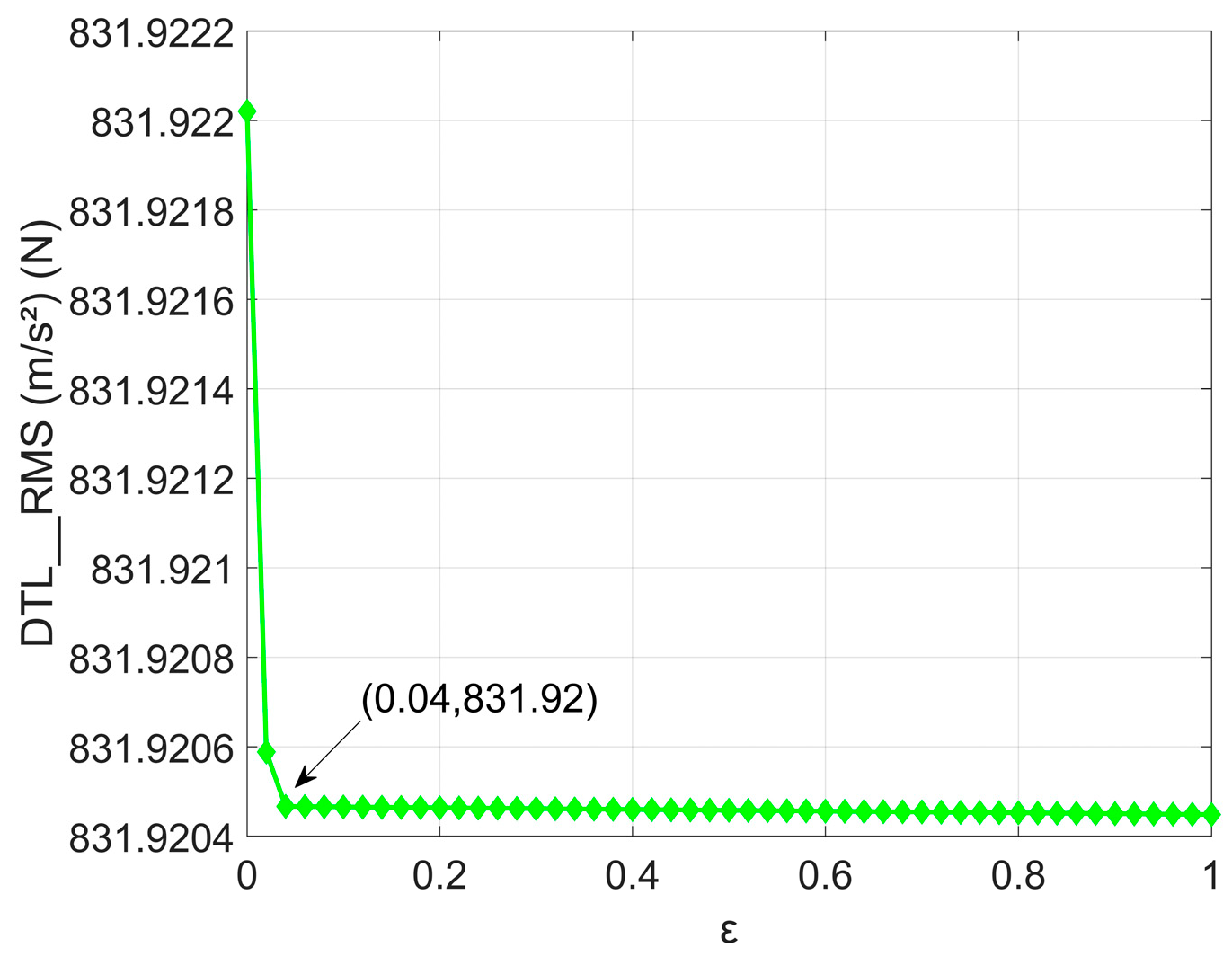
To systematically investigate the influence of spring nonlinearity on suspension dynamic performance, the parameter ε was varied within the range of (0, 1) while maintaining other optimized parameters as constant. The RMS values of BA, SWS, and DTL were analyzed as functions of ε for both parallel and series ISD configurations, with the results presented in Figure 12, Figure 13, Figure 14, Figure 15, Figure 16 and Figure 17.
For the parallel ISD suspension, distinct correlations between each performance metric and ε are observed. The RMS of BA (Figure 12) exhibits a positive correlation with parameter ε, indicating a gradual deterioration in ride comfort as nonlinearity intensifies. Conversely, the RMS of SWS (Figure 14) and DTL (Figure 16) demonstrate a clear negative correlation with ε. This trend signifies that increasing the nonlinearity degree progressively improves the suspension’s ability to limit dynamic deflection and enhances tire ground contact stability. The opposing trends establish a fundamental performance trade-off in the parallel configuration.
For the series ISD suspension, the influence of ε reveals more complex and non-monotonic behavior. As shown in Figure 13, BA initially decreases within a specific ε range, suggesting improved ride comfort, but subsequently increases as ε continues to rise. The SWS (Figure 15) and DTL (Figure 17) responses also exhibit optimal zones where performance improvements are achieved. However, beyond these optimal ranges, the benefits diminish or reverse, indicating that excessive nonlinearity can compromise performance balance in the series configuration.
Vehicle suspension design necessitates the simultaneous minimization of BA, SWS, and DTL to comprehensively enhance ride comfort and handling stability. The ε-sensitivity analysis conducted in this study provides crucial insights for suspension optimization. It reveals that the parallel and series ISD configurations respond fundamentally differently to changes in spring nonlinearity. Consequently, strategic tuning of ε, tailored to the specific suspension architecture, is imperative for achieving optimized performance trade-offs in practical suspension design applications.

6. Conclusions

This study optimized vehicle suspension dynamics by introducing a controllable degree of spring nonlinearity into ISD systems. Quarter-vehicle models for parallel and series configurations were established, and a multi-objective genetic algorithm was employed to optimize the parameters, including the nonlinearity coefficient ε, under random road excitation. The primary goal was to minimize BA, SWS, and DTL, with performance evaluated through comprehensive time-domain and frequency-domain analyses.
For the parallel configuration, the nonlinear ISD achieved a 7.98% BA reduction over the conventional suspension and a 2.04% BA reduction over the linear ISD, along with a 1.69% DTL reduction and a 0.79% DTL reduction over the linear ISD. For the series configuration, the nonlinear ISD achieved a 7.62% SWS reduction over the conventional suspension and a 0.95% SWS reduction over the linear ISD, along with a 6.42% DTL reduction and a 1.24% DTL reduction over the linear ISD.
Future work will focus on the experimental validation of these findings, extension to full-vehicle models, and the integration of advanced control strategies to fully exploit this potential.
Author Contributions

Conceptualization, X.F. and Y.S.; methodology, X.F. and Y.S.; software, J.Z.; validation, Y.P., Y.L. and T.Z.; formal analysis, Y.P. and J.Z.; investigation, X.F.; resources, Y.S.; data curation, X.F. and J.Z.; writing—original draft preparation, Y.P. writing—review and editing, Y.P., Y.L. and T.Z.; visualization, X.F.; supervision, Y.S.; project administration, X.F. and Y.S. All authors have read and agreed to the published version of the manuscript.

Funding

This research received no external funding.

Data Availability Statement

The original contributions presented in this study are included in the article. Further inquiries can be directed to the corresponding author.

Conflicts of Interest

The authors declare no conflicts of interest.

Abbreviations

The following abbreviations are used in this manuscript:
ISDInerter Spring Damper
RMSRoot mean square
BABody acceleration
SWSSuspension working space
DTLDynamic tire load
2-DOFTwo-degree-freedom

References

  1. Xu, D.; Chai, L.; Gao, Z.; Li, Y.; Wang, Y. Experimental study on driver seat vibration characteristics of crawler-type combine harvester. Int. J. Agric. Biol. Eng. 2019, 12, 90–97. [Google Scholar] [CrossRef]
  2. Kim, M.; Lee, C. Improvement of Dynamic Characteristics of Purpose-Built Vehicles Using Semi-Active Suspension System. Sensors 2024, 24, 4310. [Google Scholar] [CrossRef] [PubMed]
  3. Cui, L.; Xue, X.; Le, F.; Mao, H.; Ding, S. Design and experiment of electro hydraulic active suspension for controlling the rolling motion of spray boom. Int. J. Agric. Biol. Eng. 2019, 12, 72–81. [Google Scholar] [CrossRef]
  4. Smith, M.C. Synthesis of mechanical networks: The inerter. IEEE Trans. Autom. Control 2002, 47, 1648–1662. [Google Scholar] [CrossRef]
  5. Yang, Y.; Liu, C.; Chen, L.; Zhang, X. Phase deviation of semi-active suspension control and its compensation with inertial suspension. Acta Mech. Sin. 2024, 40, 523367. [Google Scholar] [CrossRef]
  6. Li, H.; Zhang, X.; Geng, C. Research on load adaptability of dynamic vibration absorption nonlinear inerter-spring-damper suspension. Mach. Des. Manuf. Eng. 2022, 51, 71–76. [Google Scholar] [CrossRef]
  7. Li, Y.; Han, S.; Xiong, J.; Wang, W. Comfort-oriented semi-active suspension configuration with inerter-based network synthesis. Actuators 2023, 12, 290. [Google Scholar] [CrossRef]
  8. Shen, Y.; Li, J.; Huang, R.; Yang, X.; Chen, J.; Chen, L.; Li, M. Vibration control of vehicle ISD suspension based on the fractional-order SH-GH strategy. Mech. Syst. Signal Process. 2025, 234, 112880. [Google Scholar] [CrossRef]
  9. Liu, C.; Chen, L.; Lee, H.P.; Yang, Y.; Zhang, X. A review of the inerter and inerter-based vibration isolation: Theory, devices, and applications. J. Frankl. Inst. 2022, 359, 7677–7707. [Google Scholar] [CrossRef]
  10. Filippi, M.; Magliacano, D.; Petrolo, M.; Carrera, E. Variable-kinematics finite elements for propagation analyses of two-dimensional waveguides. In Proceedings of the 30th AIAA/CEAS Aeroacoustics Conference, Rome, Italy, 4–7 June 2024; p. 3078. [Google Scholar]
  11. Li, Y.; Jiang, Z.J.; Neild, S. Inerter-based configurations for main-landing-gear shimmy suppression. J. Aircr. 2017, 54, 684–693. [Google Scholar] [CrossRef]
  12. Bubbar, K.; Buckham, B. On establishing generalized analytical phase control conditions in two body self-reacting point absorber wave energy converters. Ocean Eng. 2020, 197, 106879. [Google Scholar] [CrossRef]
  13. Du, F.; Mao, M.; Chen, Y.; Wang, Y.; Zhang, Y. Structure design and performance analysis of inerter-spring-damper suspension structure based on dynamic model and parameter optimization. J. Vib. Shock. 2014, 33, 59–65. [Google Scholar] [CrossRef]
  14. Shen, Y.; Li, Z.; Tian, X.; Ji, K.; Yang, X. Vibration suppression of the vehicle mechatronic ISD suspension using the fractional-order biquadratic electrical network. Fractal Fract. 2025, 9, 106. [Google Scholar] [CrossRef]
  15. Lu, E.; Xue, J.; Chen, T.; Jiang, S. Robust Trajectory Tracking Control of an Autonomous Tractor-Trailer Considering Model Parameter Uncertainties and Disturbances. Agriculture 2023, 13, 869. [Google Scholar] [CrossRef]
  16. Li, J.; Shang, Z.; Li, R.; Cui, B. Adaptive sliding mode path tracking control of unmanned rice transplanter. Agriculture 2022, 12, 1225. [Google Scholar] [CrossRef]
  17. Sun, J.; Wang, Z.; Ding, S.; Xia, J.; Xing, G. Adaptive disturbance observer-based fixed time nonsingular terminal sliding mode control for path-tracking of unmanned agricultural tractors. Biosyst. Eng. 2024, 246, 96–109. [Google Scholar] [CrossRef]
  18. Wang, R.; Zhang, K.; Ding, R.; Jiang, Y.; Jiang, Y. A Novel Hydraulic Interconnection Design and Sliding Mode Synchronization Control of Leveling System for Crawler Work Machine. Agriculture 2025, 15, 137. [Google Scholar] [CrossRef]
  19. Zhu, Z.; Zeng, L.; Chen, L.; Zou, R.; Cai, Y. Fuzzy adaptive energy management strategy for a hybrid agricultural tractor equipped with HMCVT. Agriculture 2022, 12, 1986. [Google Scholar] [CrossRef]
  20. Yu, Y.; Hao, S.; Guo, S.; Tang, Z.; Chen, S. Motor torque distribution strategy for different tillage modes of agricultural electric tractors. Agriculture 2022, 12, 1373. [Google Scholar] [CrossRef]
  21. Cui, B.; Cui, X.; Wei, X.; Zhu, Y.; Ma, Z.; Zhao, Y.; Liu, Y. Design and Testing of a Tractor Automatic Navigation System Based on Dynamic Path Search and a Fuzzy Stanley Model. Agriculture 2024, 14, 2136. [Google Scholar] [CrossRef]
  22. Li, Y.; Qi, B.; Bao, E.; Tang, Z.; Lian, Y.; Sun, M. Design and Analysis of a Sowing Depth Detection and Control Device for a Wheat Row Planter Based on Fuzzy PID and Multi-Sensor Fusion. Agronomy 2025, 15, 1490. [Google Scholar] [CrossRef]
  23. Shen, Y.; Jia, M.; Yang, X.; Liu, Y.; Chen, L. Vibration suppression using a mechatronic PDD-ISD-combined vehicle suspension system. Int. J. Mech. Sci. 2023, 250, 108277. [Google Scholar] [CrossRef]
  24. Jin, L.; Fan, J.; Du, F.; Zhan, M. Research on Two-Stage Semi-Active ISD Suspension Based on Improved Fuzzy Neural Network PID Control. Sensors 2023, 23, 8388. [Google Scholar] [CrossRef]
  25. Zhang, Y.; Ren, C.; Wang, Y.; Meng, H. Model-free Adaptive Control of Vehicle-seat System Using Nonlinear Energy Sink Inerter. Noise Vib. Control 2025, 45, 218–224. [Google Scholar]
  26. Yang, X.; Zhang, T.; Shen, Y.; Liu, Y.; Bui, V.; Qiu, D. Tradeoff analysis of the energy-harvesting vehicle suspension system employing inerter element. Energy 2024, 308, 132841. [Google Scholar] [CrossRef]
  27. Zhu, Z.; Sui, C.; Xu, J. Nonlinear Dynamic Characteristics of Semi-Active Suspension System with SMA Spring Based on Hysteretic Nonlinear Theory. Key Eng. Mater. 2010, 458, 265–270. [Google Scholar] [CrossRef]
  28. Huang, Y.; Na, J.; Wu, X.; Liu, X.; Guo, Y. Adaptive control of nonlinear uncertain active suspension systems with prescribed performance. ISA Trans. 2015, 54, 145–155. [Google Scholar] [CrossRef] [PubMed]
  29. Lauß, T.; Sterl, D.; Oberpeilsteiner, S.; Steiner, W. Identification of a nonlinear spring and damper characteristics of a motorcycle suspension using test ride data. PAMM 2018, 18, e201800143. [Google Scholar] [CrossRef]
  30. Zhao, H.; Fu, C.; Zhu, W.; Lu, K.; Zheng, Z. Dynamic characteristics and sensitivity analysis of a nonlinear vehicle suspension system with stochastic uncertainties. Nonlinear Dyn. 2024, 112, 21605–21626. [Google Scholar] [CrossRef]
  31. Sun, Z.; Wang, J. Vehicle ride comfort analysis based on the nonlinearity of leaf spring. In Proceedings of the 2009 China Society of Automotive Engineers Annual Conference, Changchun, China, 11 March 2009; pp. 775–780. [Google Scholar]
  32. GB/T 7031-2005; Mechanical Vibration-Road surface Profiles-Reporting of Measured Data. Standards Press of China: Beijing, China, 2005.
  33. Song, H. Research on Vertical Vibration Suppression and SH-PDD Control for Dynamic-Inertia Suspension of In-Wheel Motor Drive Vehicles. Master’s Thesis, Jiangsu University, Zhenjiang, China, 2022. [Google Scholar] [CrossRef]
Figure 1. Model of linear ISD suspension: (a) 1/4 parallel vehicle ISD suspension, where the suspension spring, inerter, and damper are connected in parallel; (b) 1/4 series vehicle ISD suspension, where the inerter and damper are arranged in series, and this series branch is connected in parallel with the suspension spring.
Machines 13 01011 g001
Figure 2. Road input displacement.
Machines 13 01011 g002
Figure 3. Comparison of BA of parallel ISD.
Machines 13 01011 g003
Figure 4. Comparison of SWS of parallel ISD.
Machines 13 01011 g004
Figure 5. Comparison of DTL of parallel ISD.
Machines 13 01011 g005
Figure 6. Comparison of BA of series ISD.
Machines 13 01011 g006
Figure 7. Comparison of SWS of series ISD.
Machines 13 01011 g007
Figure 8. Comparison of DTL of series ISD.
Machines 13 01011 g008
Figure 9. Responses of body acceleration in the frequency domain: (a) parallel ISD; (b) series ISD.
Machines 13 01011 g009
Figure 10. Responses of suspension working space in the frequency domain: (a) parallel ISD; (b) series ISD.
Machines 13 01011 g010
Figure 11. Responses of dynamic tire load in the frequency domain: (a) parallel ISD; (b) series ISD.
Machines 13 01011 g011
Figure 12. Variation in BA with ε of parallel ISD.
Machines 13 01011 g012
Figure 13. Variation in BA with ε of series ISD.
Machines 13 01011 g013
Figure 14. Variation in SWS with ε of parallel ISD.
Machines 13 01011 g014
Figure 15. Variation in SWS with ε of series ISD.
Machines 13 01011 g015
Figure 16. Variation in DTL with ε of parallel ISD.
Machines 13 01011 g016
Figure 17. Variation in DTL with ε of series ISD.
Machines 13 01011 g017
Table 1. Parameters of the passive suspension model.
DescriptionParametersValue
Sprung massm1320 kg
Unsprung massm245 kg
Stiffness of tirek2190,000 N·m−1
Cutoff Frequencyf00.01 Hz
Vehicle Speedv20 m·s−1
Road roughness coefficientG(n0)2.56 × 10⁻⁵ m3·cycle−1
Table 2. Parameter settings for the variable boundary conditions.
Optimized Parameterslbiubi
Linear ISDSuspension Spring Stiffness k1/(N·m−1)030,000
Inertance b/(kg)0300
Suspension Damping Coefficient c/(N·s·m−1)03000
Nonlinear ISDSuspension Spring Stiffness k1/(N·m−1)030,000
Inertance b/(kg)0300
Suspension Damping Coefficient c/(N·s·m−1)03000
ε01
Cubic Stiffness Coefficient k3/(N·m−3)0300
Table 3. Optimized parameters for the linear and nonlinear ISD suspension configurations.
Optimal ParametersValues (Parallel)Values (Series)
Linear ISDSuspension Spring Stiffness k1/(N·m−1)13,00517,706
Inertance b/(kg)2.75298.64
Suspension Damping Coefficient c/(N·s·m−1)12401297
Nonlinear ISDSuspension Spring Stiffness k1/(N·m−1)11,59218,965
Inertance b/(kg)1.01270.27
Suspension Damping Coefficient c/(N·s·m−1)12041351
ε0.180.07
Cubic Stiffness Coefficient k3/(N·m−3)8126
Table 4. Dynamic performance indices comparison for the parallel ISD suspension.
NameConventional SuspensionParallel Linear ISDDecreaseNonlinear Parallel ISDDecrease
RMS of body acceleration (m·s−2)1.18681.11635.94%1.09217.98%
RMS of suspension working space (m)0.01050.009410.48%0.00968.57%
RMS of dynamic tire load (N)8888800.9%8731.69%
Table 5. Dynamic performance indices comparison for the series ISD suspension.
NameConventional SuspensionSeries Linear ISDDecreaseNonlinear Series ISDDecrease
RMS of body acceleration (m·s−2)1.18681.13604.28%1.15682.53%
RMS of suspension working space (m)0.01050.00986.67%0.00977.62%
RMS of dynamic tire load (N)8888425.18%8316.42%
Disclaimer/Publisher’s Note: The statements, opinions and data contained in all publications are solely those of the individual author(s) and contributor(s) and not of MDPI and/or the editor(s). MDPI and/or the editor(s) disclaim responsibility for any injury to people or property resulting from any ideas, methods, instructions or products referred to in the content.