Abstract
Direct power control (DPC) is a widely accepted control scheme utilized in renewable energy applications owing to its several advantages over other control mechanisms, including its simplicity, ease of implementation, and faster response. However, DPC suffers from inherent drawbacks and limitations that constrain its applicability. These restrictions include notable ripples in active power and torque, as well as poor power quality brought on by the usage of a hysteresis regulator for capacity management. To address these issues and overcome the limitations of DPC, this study proposes a novel approach that incorporates artificial neural networks (ANNs) into DPC. The proposed technique focuses on doubly fed induction generators (DFIGs) and is validated through experimental testing. ANNs are employed to recompense for the deficiencies of the hysteresis controller and switching table. The intelligent DPC technique is then compared to three other strategies: classic DPC, backstepping control, and integral sliding-mode control. Various tests are conducted to compare the ripple ratio, current quality, durability, response time, and reference tracking. The validity and robustness of the proposed intelligent DPC for DFIGs are verified through both simulation and experimental results obtained from the MATLAB/Simulink environment and the Real-Time Interface (RTI) of the dSPACE DS1104 controller card. The results confirm that the intelligent DPC outperforms conventional control strategies in terms of stator current harmonic distortion, dynamic response, power ripple minimization, reference tracking accuracy, robustness, and overshoot reduction. Overall, the intelligent DPC exhibits superior performance across all evaluated criteria compared to the alternative approaches.
1. Introduction
1.1. Overview
The growing importance of renewable energy sources stems from their affordability and positive environmental impact in reducing greenhouse gas emissions. Among these sources, wind power has gained significant popularity and usage due to advancements in technology, ease of control, and relatively low production costs []. However, a major challenge associated with wind energy is its dependence on variable wind speeds, which adversely affects power quality. This leads to fluctuations in electrical output, disturbances in the generator’s electromagnetic torque, and deviations from the wind turbine system’s maximum power point []. Despite their limitations, fixed-speed wind energy systems remain popular because of the challenges associated with variable-speed wind turbines [,]. In contrast, accurate and effective control approaches are required for variable-speed wind energy systems to effectively handle energy fluctuations and ensure the delivery of high-quality power.
When designing controllers for variable-speed applications, the choice of a suitable generator is essential []. When compared to alternative options, the DFIG is commonly chosen because of its ease of control, low maintenance costs, and durability []. DFIGs dominate the wind energy system sector, accounting for more than 50% of the generators used, but other options like squirrel cage induction generators, synchronous generators, and switched reluctance generators are also utilized [,,,].
Various control methods exist for managing DFIG-based wind turbine systems. The conventional FOC control is commonly adopted in realistic applications []. Nevertheless, implementing FOC for DFIG-based turbines presents challenges such as torque and active power fluctuations and the system’s response delay owing to utilizing PI linear controllers []. The accuracy of the model significantly affects the effectiveness of FOC compared to alternative methods. The design of the PI parameters has a major impact on the dynamics of wind-driven DFIG controlled by FOC. These parameters are typically determined for only one operating point, limiting adaptability to changes in other operating points [].
1.2. Literature Review
Numerous approaches have been suggested to enhance the dynamic response of electrical devices and replace the FOC methodology. One widely adopted and straightforward approach is direct torque command (DTC) [], initially used for controlling asynchronous motors and later extended to all electrical machines []. DTC offers a relatively inexpensive alternative to FOC [] and provides a remarkably rapid dynamic response. Another method with similar principles is direct power control (DPC), which employs a switching table to regulate the inverter []. DPC exhibits similar characteristics and benefits to DTC but diverges in the choice of reference quantities for control. While DTC utilizes flux and torque as references, DPC utilizes reactive and active power references.
The DPC technique has found practical applications in managing control systems for both asynchronous and synchronous generators. It offers a simple control scheme and cost-effectiveness, surpassing traditional methods such as Field-Oriented Control (FOC) []. DPC stands out for its superior dynamic response, while FOC is sensitive to parameter variations and non-ideal conditions, which may result in ripples in generated power and poor quality of generated current, which can shorten the lifespan of electrical appliances. To tackle these problems, recent studies have proposed multiple solutions to enhance the efficiency and performance of DPC.
Notably, artificial intelligence and nonlinear methods have shown promising enhancements, mainly in response time [,]. Despite that, these methods require skilled parameter adjustments and longer tuning periods, although proficiency improves with experience. Despite these challenges, DPC has emerged as an ideal solution for managing electric generators, thanks to the simple structure and straightforward implementation. Several research papers that concentrate on renewable energies provide support for this viewpoint [,,,].
For example, a specific application of DPC in controlling DFIG in wind turbines was demonstrated in [], showcasing highly efficient energy ripple reduction compared to FOC. Similarly, Ref. [] explored the application of DPC in controlling synchronous generators. These references [,] and other studies emphasize the use of DPC to decrease fluctuations and current harmonics as well, although the complete elimination of ripples remains a challenge.
To enhance the efficiency and characteristics of DPC, several proposed solutions aim to enhance this control strategy by combining it with other controllers, including nonlinear regulators and artificial intelligence methodologies. In one study [], DPC is integrated with backstepping control to enhance the quality of the generated currents. While this integration increases the complexity and execution difficulty of DPC, it significantly improves its characteristics compared to standalone DPC.
Furthermore, SMC control is introduced as an alternative to address the limitations of DPC []. This adaptive method eliminates the need for hysteresis controllers and switching tables, resulting in a notable improvement in current quality. However, this modification increases the experimental cost associated with the DPC strategy.
In another study [], genetic algorithms and fuzzy logic are utilized to enhance the performance of DPC of a wind-driven DFIG. The results demonstrate the effectiveness of these intelligent methods in improving DPC performance. Additionally, vector control is combined with DPC to regulate DFIG-based WECS [], demonstrating the enhanced performance of vector control-based DPC compared to standalone DPC.
The application of artificial neural networks in DPC has been employed to compensate for hysteresis comparators and switching tables []. This approach leads to an improved dynamic response and substantial reduction in torque and current ripples when compared to conventional DPC.
Ensuring the stability of wind farm power generation and mitigating system fluctuations requires effective management of network frequency and reactive power, taking advantage of technological advancements. Transmission system operators have introduced specific network codes to address system oscillations and facilitate wind farm connections, thereby minimizing fluctuations, improving network reliability, and reducing the impact on electrical devices. High-quality energy is crucial in this context as it extends device lifespan, reduces maintenance needs, and lowers industrial costs [,].
To overcome the limitations of DPC, a combination of neural networks and pulse width modulation (PWM) is utilized. PWM is preferred over Space Vector Modulation (SVM) due to ease of application. The intelligent DPC method utilizes PWM to regulate the Rectifier Side Converter (RSC), while an uncontrolled inverter is employed for the Grid Side Converter (GSC).
1.3. Contribution
This study explores the use of artificial neural network controllers for intelligent DPC in DFIG-based wind turbines. It compares the performance of intelligent DPC with classic DPC, backstepping control, and integral sliding-mode control. Experimental work focuses on DPC with ANN controllers specifically designed for wind-driven DFIG. The proposed DPC technique offers a simpler arrangement, improved robustness, and easier implementation compared to other control methods. The effectiveness of these control techniques is assessed through a simulation study with regard to current quality, durableness, reference tracking, and ripple limitation. The primary contribution of this study is a comprehensive experimental comparative study involving these four methods using a 1.5 KW DFIG. A schematic diagram (Figure 1) illustrates the design steps, evaluating tests, comparative analysis, and experimental verification. The main objectives of this study are as follows:
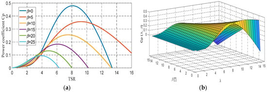
Figure 1.
curves: (a) 2D plot and (b) a surface plot.
- Validating the intelligent DPC method proposed in this study through experimentation using dSPACE.
- Verifying the efficacy of the proposed DFIG controller by assessing its impact on reactive power, active power, torque ripples limitations and the mitigation of THD in stator currents, using a real wind speed profile.
- Conducting a comparative analysis between integral sliding-mode control, backstepping control, traditional DPC techniques, and intelligent DPC techniques.
- Addressing the limitations and issues associated with DPC and proposing solutions to overcome them.
1.4. Study Arrangement
The study is divided into six sections, covering various aspects from introduction to references. The first section introduces the topic. Section 2 explains the dynamic modeling of the WECS, including both the wind turbine and the DFIG. Section 3 describes the four control techniques used. Emulating tests are introduced in Section 4. Section 5 introduces and discusses the experimental results captured using the DSPACE card. At last, Section 6 outlines the fundamental conclusions and provides perspectives based on the study.
2. WECS Modeling
2.1. Modeling of WT System
Wind turbines use a generator to transform the kinetic energy of the wind into electrical power. The wind flow spins the turbine blades, which drive a shaft connected to a gearbox inside the turbine housing. This increases the rotational speed to match the generator’s rated speed, allowing it to convert the energy into electricity using magnetic fields [].
Equation (1) represents the power generated by the WECS.
In the present study, the power coefficient is represented by the following equation:
The TSR can be defined as follows:
The equation provided below describes the connection between electromagnetic and mechanical torques:
Figure 1 illustrates the power coefficient curves, depicting the relationship between Cp (λ, β) and λ for various β values. The peak value of Cp (λ, β) (Cp (λ, β)max= 0.487) is attained at λopt = 8.24 and β = 0°.
2.2. Modeling of DFIG
The following expressions are presented below, illustrating the general dynamic equations of the DFIG in the Park reference frame [,]:
Voltage equations:
Flux equations:
Power equations:
where:
Electromagnetic torque:
3. Adopted Control Strategies
3.1. Classical DPC for RSPC
The DPC strategy, popular in renewable energy, differs from direct torque control in terms of references used and has gained popularity due to its simplicity and user-friendliness []. Accurate measuring devices are required for current and voltage measurements []. The DFIG-WT system employs two hysteresis controllers for power regulation and a look-up table for inverter transistor control. DPC eliminates the need for block current PWM modulation and utilizes power estimation for active and reactive power error calculation []. The look-up table takes the active and reactive power errors and sectors as inputs and provide three outputs to control the inverter [].
Figure 2 illustrates the DPC strategy for the DFIG-WT, emphasizing its easy implementation as a significant advantage.
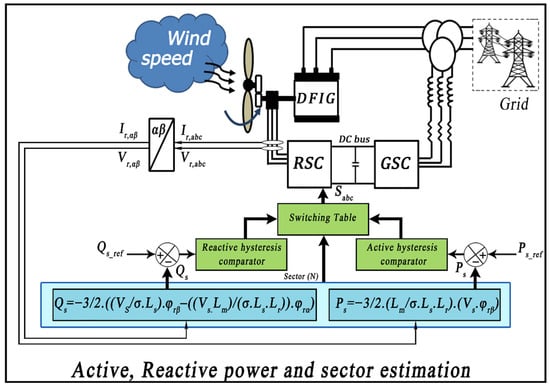
Figure 2.
Conventional DPC approach.
To estimate capacities, rotor flux is required. Relationship (10) is utilized to compute the d-q rotor flux components as
The calculation for the rotor flux amplitude value is as follows:
Equation (12) describes the correlation between rotor flux and rotor voltage, represented as
The rotor flux angle is determined using Equation (13), which is then utilized to calculate the regions associated with the reference voltage ray presence in the following manner:
Equations (14) and (15) are employed for the estimation of the capacities of the DFIG.
Equations (14) and (15) are used to estimate Qs and Ps. Comparing the estimated powers (∆Qs and ∆Ps) with the desired powers yields the digitized signals HP and HQ. The predefined switching table, considering HP, HQ, and N, determines the selection of switching states []. The errors of Qs and Ps, along with the corresponding working sector “sector (N),” are introduced in Table 1.

Table 1.
The look-up table used by the classical DPC.
3.2. Backstepping Control for RSPC
The backstepping method is a recursive method utilized to stabilize nonlinear dynamical systems by breaking down complex problems into simpler design steps using a virtual control []. The performance and stability of the system are ensured by employing a Lyapunov function to guide the virtual control []. In this study, errors are characterized as the deviations between the calculated and reference power signals [].
The derivatives of these quantities are expressed as follows:
The selected Lyapunov function is structured by
The derivatives of each error Lyapunov function are expressed as follows:
The chosen control voltages of the backstepping controller proposed in Figure 3 are expressed by Equation (20) as follows:
where and are positive constants.

Figure 3.
DFIG control using the backstepping method.
3.3. Integral Sliding-Mode Control for RSPC
Integral sliding-mode control (ISMC) improves upon SMC by incorporating an integral term to overcome its limitations. SMC utilizes a discontinuous control signal to guide the system state toward a desired sliding surface, demonstrating robustness against nonlinearities, uncertainties, and active disturbances in various applications [,]. However, the practical implementation of SMC is hindered by the presence of the chattering phenomenon [,].
To address this limitation, this study proposes an approach called ISMC specifically tailored for wind-driven DFIG. In this strategy, the rotor current’s components are transformed into the synchronous rotating frame via utilizing the relationship below.
with
where .
Accordingly, Equation (22) can be then reformulated to be
where
The expression for the switching variables is given by the following equation:
where , is a sliding constant coefficient, and . The switching variables dynamics can be then expressed by
Substituting (21) into (28) yields the following:
The Lyapunov function under consideration is defined as follows:
To maintain stability, the derivative of Equation (22) must be negative.
Substituting from Equation (27) in Equation (31), the next expression is obtained:
Here, and . Equation (32) demonstrates that when and are large, the dynamics of the control variables converge to zero.
3.4. Proposed Intelligent DPC Control for RSPC
In this study, a new approach is proposed to overcome the limitations of the conventional DPC strategy. The proposed method incorporates artificial neural networks (ANNs) and pulse width modulation (PWM) strategy. This novel technique offers a robust and simplified control solution that is both applicable and exhibits a faster dynamic in comparison with the traditional DPC strategy [,]. The proposed control method represents a significant departure from conventional DPC, replacing the classical look-up table with the PWM technique and employing artificial neural network controllers (ANNCs) rather a hysteresis regulator. This modification results in a more compact approach in contrast to the traditional DPC strategy [,,,].
The developed DPC strategy is depicted in Figure 4.
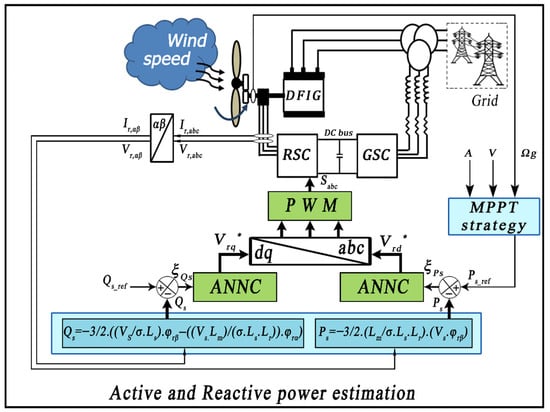
Figure 4.
Proposed intelligent DPC method.
The strategy utilizes an ANN, a widely used technique in artificial intelligence control, to regulate reactive and active powers. Its goal is to achieve stable electric current output from the DFIG, minimizing fluctuations in current, active power, and torque, while reducing total harmonic distortion (THD) to a minimum. The constants of the ANN controllers employed in this study are detailed in Table 2. The neuron’s characteristic equation in the lth layer is represented by the following []:
where : input vector; : synaptic weights of neuron j in layer l; : bias input.

Table 2.
ANN variables.
Static Multilayer Perceptrons (MLPs) were chosen as the neural controllers in this study. The architectural configurations of these MLPs can be seen in Figure 5. Each MLP controller had two neurons in its input layer, representing the power reactive error () and its derivative () and the power active error () and its derivative (). Two hidden layers and a single neuron output layer were also included in the MLPs [,]. The output neuron was responsible for developing the reference d-q components of rotor voltage and .
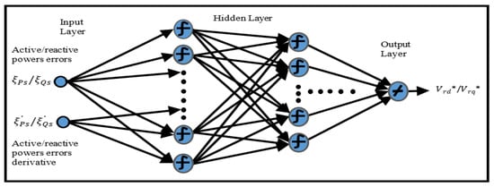
Figure 5.
Architectural configurations of the employed MLPs.
The MSE evolution is depicted in Figure 6a,b, illustrating the relationship between the number of iterations and the Mean Square Error (MSE) for the reactive and active power controllers, respectively. It is evident from the graphs that both controllers exhibit a low MSE, reaching values of 3.6155 × 10⁻⁴ and 2.9912 × 10⁻⁴, respectively, at the 100th iteration. For a comprehensive understanding of the entire system, Figure 7 provides a visual representation of its structure.
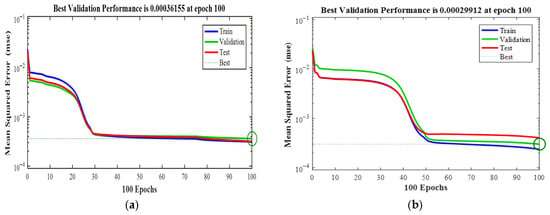
Figure 6.
Training performance curve (MSE): (a) active power; (b) reactive power controllers.
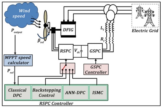
Figure 7.
Overall layout of the system under study.
4. Simulation Results
To assess the effectiveness of the suggested controller, a simulation test is conducted using the MATLAB/Simulink program. The simulation employs a 1.5 KW DFIG model, representing a wind turbine. The global system parameters relevant to the study can be found in Table A1 of the Appendix A.
This section presents two different test cases to validate the resilience of the designed strategy. The first case involves subjecting the system to a sudden wind speed variation, while the second case utilizes a diverse real wind speed profile obtained from Al Hoceima city in northern Morocco. The objective of these test cases is to examine how the proposed method behaves when confronted with changes in reference signals, providing insights into its performance.
4.1. First Test Case
The initial test case involved utilizing varying wind speeds to examine how the designed control system responds to changes in wind conditions. This particular study focused on the wind behavior observed in Al Hoceima, a city in Morocco, as depicted in Figure 8. The results of this test are presented in Figure 9, Figure 10, Figure 11, Figure 12, Figure 13, Figure 14, Figure 15, Figure 16, Figure 17, Figure 18, Figure 19, Figure 20, Figure 21, Figure 22, Figure 23, Figure 24, Figure 25, Figure 26, Figure 27, Figure 28 and Figure 29. Figure 9 displays the power coefficient (Cp), which demonstrates an approximate value of 0.487 that fluctuates with varying wind speed. It can be observed that the Cp value follows the same trend as the wind speed. Figure 10 illustrates the turbine’s tip speed ratio (λ), which also varies in accordance with the changing wind conditions. The maximum λ recorded is approximately 6.90, while the minimum speed is approximately 8.24. Figure 11 depicts the rotor speed of DFIG, which also fluctuates in response to the changing wind speed.
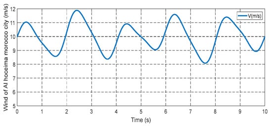
Figure 8.
Wind speed profile.
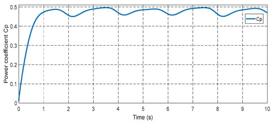
Figure 9.
Power coefficient.
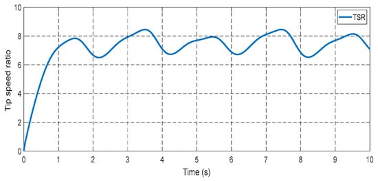
Figure 10.
Tip speed ratio.
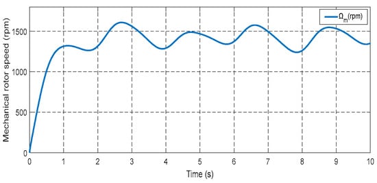
Figure 11.
Rotor speed.
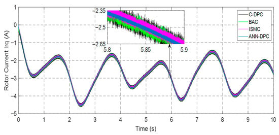
Figure 12.
Rotor current irq.
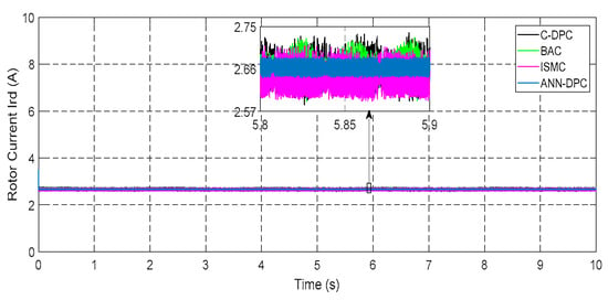
Figure 13.
Rotor current ird.
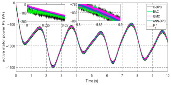
Figure 14.
Active power Ps.
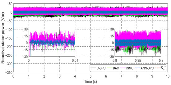
Figure 15.
Reactive power Qs.
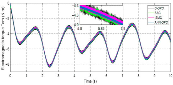
Figure 16.
Developed torque Tem.
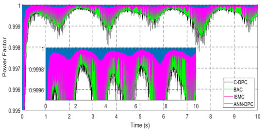
Figure 17.
Power factor.
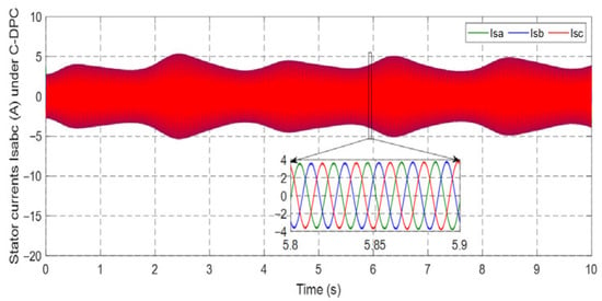
Figure 18.
Stator current under C-DPC.
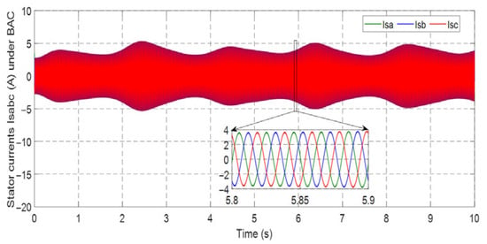
Figure 19.
Stator current isabc under BSC.
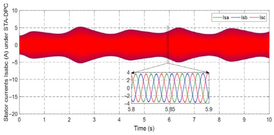
Figure 20.
Stator current isabc under ISMC.
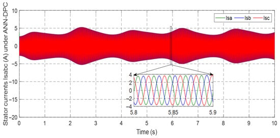
Figure 21.
Stator current under ANN-DPC.
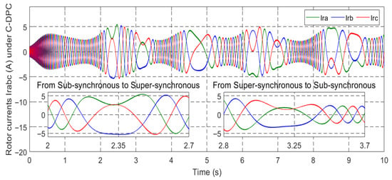
Figure 22.
Rotor current under C-DPC.
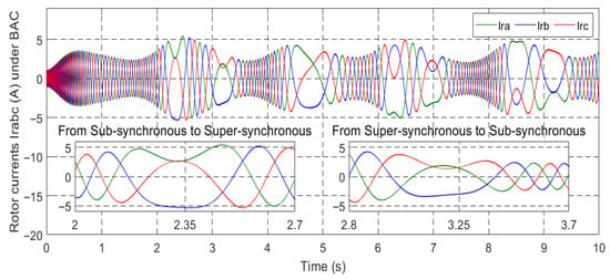
Figure 23.
Rotor current irabc under BSC.
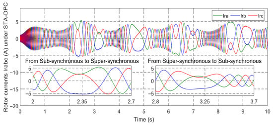
Figure 24.
Rotor current irabc under ISMC.
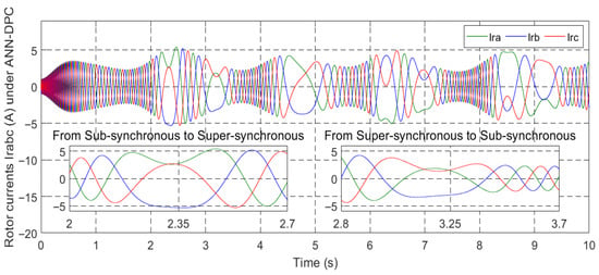
Figure 25.
Rotor current under ANN-DPC.
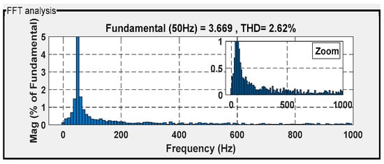
Figure 26.
THD for isa under C-DPC.
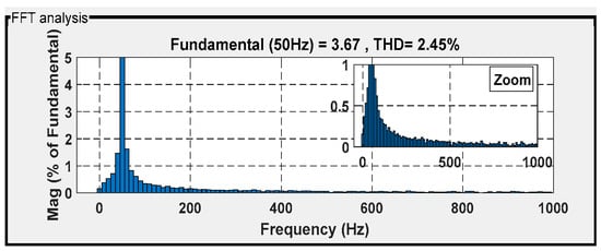
Figure 27.
THD for isa under BSC.
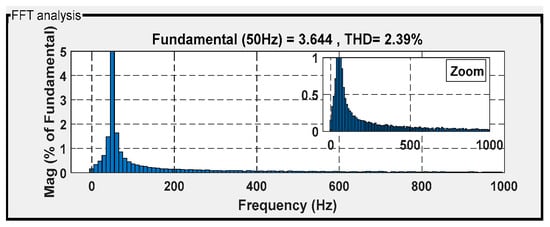
Figure 28.
THD for isa under ISMC.
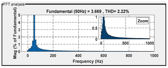
Figure 29.
THD for isa under ANN-DPC.
Figure 12, Figure 13, Figure 14, Figure 15 and Figure 16 demonstrate that all types of control successfully track their reference values for the currents irq and ird, electromagnetic torque Tem, and stator active and reactive powers. The ANN-DPC control outperforms the other controls, exhibiting a faster dynamic, minimal power curve overshoot, and reduced fluctuations. The variations in generated power Ps and torque follow the wind variation considering the adoption of the MPPT topology. Figure 12, Figure 13, Figure 14 and Figure 15 show that the power Ps and current irq have similar patterns, while the reactive power Qs and current ird vary similarly. This confirms that Ps depends on irq’s quadrature component, and Qs depends on ird’s direct component. These observations validate the successful decoupling of the machine.
Examining Figure 14 reveals that the stator active power Ps remains negative, indicating the DFIG is in generating mode. Furthermore, Figure 16 approves that the generator’s torque Tem is thoroughly proportional to the stator’s active power Ps, as shown in Figure 14. Thus, the active power serves as a representation of the electromagnetic torque. Additionally, Figure 17 demonstrates that the reactive power Qs remains at zero (Qs-ref = 0 VAR) [], ensuring operation with a unity power factor.
Figure 18, Figure 19, Figure 20, Figure 21, Figure 22, Figure 23, Figure 24 and Figure 25 showcase the current profiles of the stator and rotor windings for the four control techniques. The currents’ values are influenced by the system and the adopted wind speed profile at Al Hoceima city in Morocco.
Figure 26, Figure 27, Figure 28 and Figure 29 show the current THD obtained under the four controllers. Among them, the classical direct power control (DPC) technique demonstrated significant distortion, with a THD of 2.62%. The backstepping control technique followed with a THD of 2.45%, while the internal model sliding-mode control (ISMC) technique achieved a THD of 2.39%. The intelligent direct power control (DPC) strategy achieved the best waveform conformity, with an acceptable THD of 2.22% (with respect to the IEEE-519 standard).
4.2. Second Test Case
The purpose from the test is to evaluate the ability of the proposed controller to track set-points. The test aims to confirm the robustness of the control in handling sudden changes in references. The wind profile used in this test, depicted in Figure 30, showcases the characteristics of the proposed strategy during various speed transitions: 8 m/s → 10 m/s → 11.5 m/s → 10 m/s → 8 m/s.
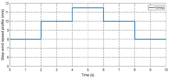
Figure 30.
Step wind speed profile.
The power coefficient, as shown in Figure 31, exhibits a similar pattern to the changes in wind speed. This relationship also holds true for both the tip speed ratio (Figure 32) and the rotor speed (Figure 33).
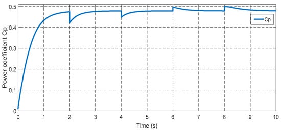
Figure 31.
Power coefficient.
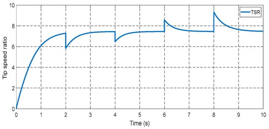
Figure 32.
Tip speed ratio.
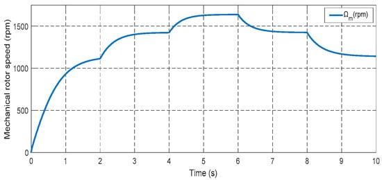
Figure 33.
Mechanical rotor speed.
Figure 34 and Figure 35 illustrate the characteristics of the d-q rotor currents. The direct rotor current maintains a constant value, while the quadrature rotor current assumes a reactive power profile. Additionally, the quadrature rotor current represents active power, and its magnitude increases alongside the active power increment.
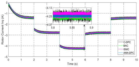
Figure 34.
Generator current irq.
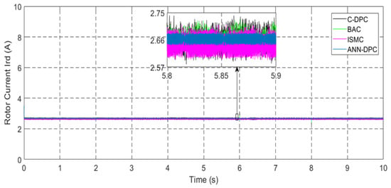
Figure 35.
Generator current ird.
The graph for active power is shown in Figure 36. Interestingly, changes in wind speed do not affect the reactive power, as illustrated in Figure 37. Throughout the simulation period, the reactive power remains zero with minor fluctuations. It can be also noted that the torque, and quadrature current exhibit similar trends to the active power, as seen in Figure 38. When active power becomes negative, it signifies that the machine is in generating mode.
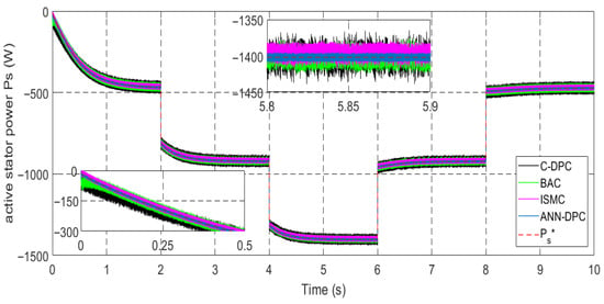
Figure 36.
Stator active power Ps.
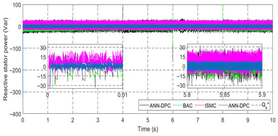
Figure 37.
Stator reactive power Qs.
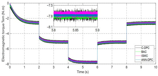
Figure 38.
Electromagnetic torque Tem.
Figure 39 displays the power factor of the DFIG. According to the figure, the power factor has a value of approximately 0.99998, showcasing slight fluctuations between 0 and 2 s. By operating with zero reactive power, the DFIG achieves a power factor of unity, indicating an efficient utilization of electrical power.
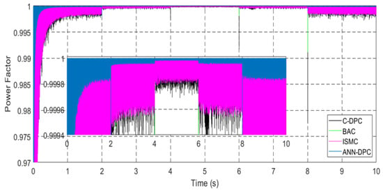
Figure 39.
Power factor.
Figure 40, Figure 41, Figure 42, Figure 43, Figure 44, Figure 45, Figure 46 and Figure 47 display the behavior of stator and rotor currents under the four control methods. These figures indicate that the changes in the currents exhibit a sinusoidal form and are influenced by variations in wind speed. As the wind speed increases, the current produced by the generator also increases. Notably, despite the sudden variations in the wind profile, the frequency remains constant at fs = 50 Hz.
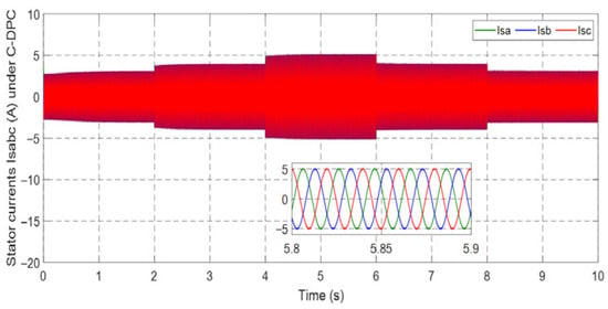
Figure 40.
Stator current under C-DPC.
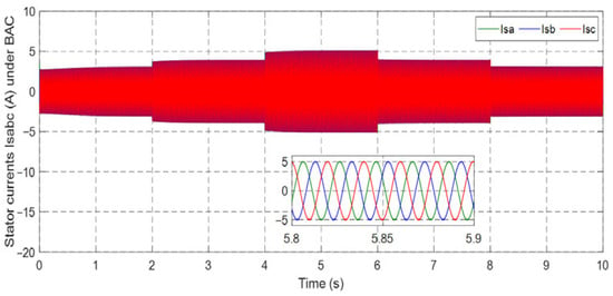
Figure 41.
Stator current isabc under BAC.
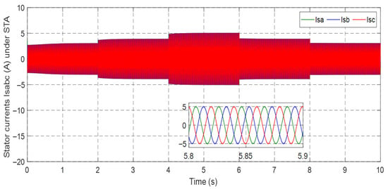
Figure 42.
Stator current isabc under ISMC.
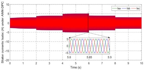
Figure 43.
Stator current under ANN-DPC.
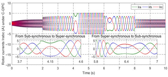
Figure 44.
Rotor current under C-DPC.
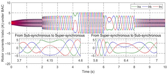
Figure 45.
Rotor current irabc under BAC.
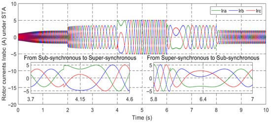
Figure 46.
Rotor current irabc under ISMC.
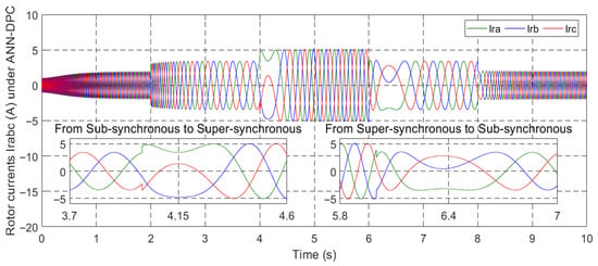
Figure 47.
Rotor current under ANN-DPC.
Figure 48, Figure 49, Figure 50 and Figure 51 provide the THD of the current obtained using four different controllers in the presence of a steep wind speed change. Among the controllers, DPC showed the highest level of waveform deformation, resulting in a THD of 1.05%. The backstepping control technique exhibited a slightly lower THD of 0.82%, while the internal model sliding-mode control (ISMC) technique achieved a further improvement with a THD of 0.76%. The most effective controller in terms of waveform conformity was the intelligent DPC strategy, which achieved an impressive THD of 0.46%, adhering to the standards set by the IEEE-519 standard.
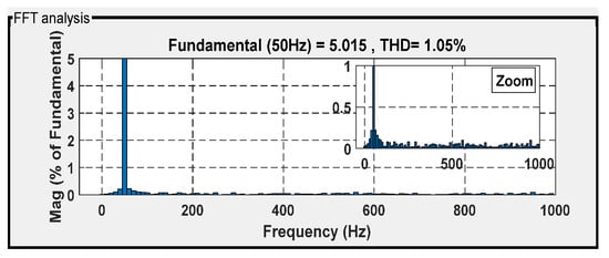
Figure 48.
THD for isa under C-DPC.
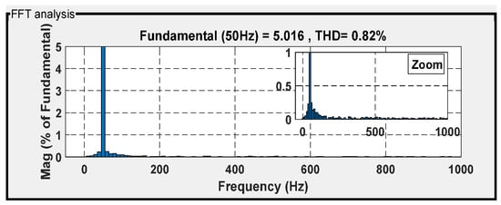
Figure 49.
THD for isa under BAC.
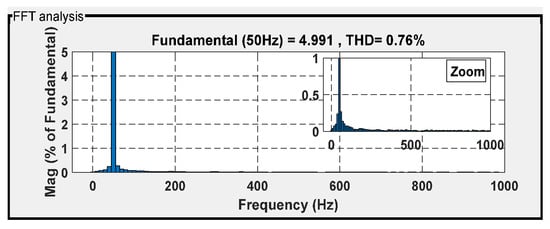
Figure 50.
THD for isa under ISMC.
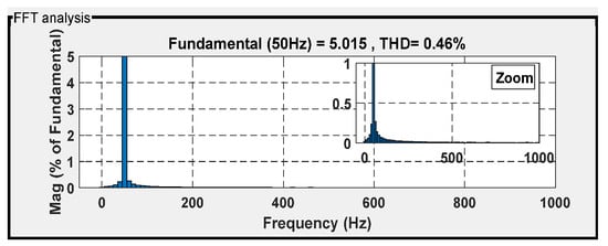
Figure 51.
THD for isa under ANN-DPC.
The analytical comparative study between the ISMC and the proposed ANN-DPC is summarized in Table 3. The table highlights the significant improvements achieved by ANN-DPC in various performance metrics. These enhancements include precise tracking of the set-point, a significant decrease in ripples, optimization of response and rise times, and harmonics minimization.

Table 3.
Comparison between ISMC and ANN-DPC.
Table 4 presents a comparison between the designed ANN-DPC and various controllers found in the existing literature. It is important to note that these studies were conducted under different conditions, making it challenging to find works carried out under identical circumstances. The comparison evaluates multiple performance indexes. Notably, ANN-DPC demonstrates outstanding performance in terms of the THD of the stator currents, response time, and rise time when compared to the other controllers. The results indicate that ANN-DPC consistently achieved optimal performance across these parameters.

Table 4.
Comparative analysis of the proposed ANN-DPC method and methods employed in recent studies.
5. Experimental Validation
Figure 52 illustrates the experimental setup designed to validate the simulation results. The setup consists of a 1.5 kW DFIG (Siemens AG, Munich, Germany), a power inverter (Schneider Electric, Rueil-Malmaison, France), a PC, and a dSPACE DS1104 R&D control board (dSPACE GmbH, Paderborn, Germany) interfaced with MATLAB/Simulink 2020 and the Real-Time Workshop environment. The inverter is operated using a PWM strategy generated by the DS1104 board, which produces 5 V logic signals to control the IGBTs. The PWM carrier frequency was set to 10 kHz with a dead time of 2 μs to prevent shoot-through. The sampling rate was also fixed at 10 kHz to ensure synchronization between data acquisition and control execution. Voltage and current measurements were obtained through LEM-type sensors (LEM International SA, Geneva, Switzerland) with an accuracy of ±0.5%, and the acquired signals were filtered using first-order low-pass filters with a cutoff frequency of 1 kHz to reduce measurement noise.
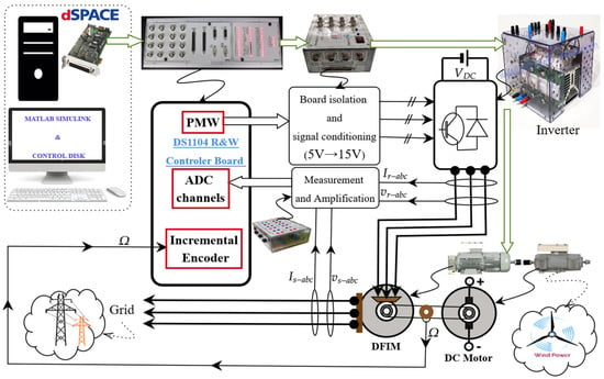
Figure 52.
Design of the implementation approach for the proposed method.
The DS1104 executed the control algorithm with an average computation time of approximately 100 μs per control cycle, ensuring real-time operation without delay. The chosen switching frequency provided a balance between total harmonic distortion (THD ≈ 3.8%) and switching losses. Thermal monitoring confirmed that the inverter operated safely below its thermal limits during continuous operation. Figure 52 also depicts the communication interface between the dSPACE DS1104 board and the DFIG system, highlighting the real-time interaction and effectiveness of the proposed control strategy.
Two specific tests are designed to evaluate the control’s robustness, mirroring the tests conducted in the last section to validate the simulation results and observe the control’s dynamic response.
The outcomes of this experimental work are depicted in Figure 53, Figure 54, Figure 55, Figure 56, Figure 57, Figure 58, Figure 59, Figure 60, Figure 61, Figure 62, Figure 63, Figure 64, Figure 65, Figure 66, Figure 67, Figure 68, Figure 69, Figure 70, Figure 71, Figure 72, Figure 73 and Figure 74. Figure 53, Figure 54, Figure 55, Figure 56, Figure 57, Figure 58, Figure 59, Figure 60, Figure 61, Figure 62 and Figure 63 illustrate the experimental results for variable wind speed, while Figure 64, Figure 65, Figure 66, Figure 67, Figure 68, Figure 69, Figure 70, Figure 71, Figure 72, Figure 73 and Figure 74 showcase the experimental findings for step wind speed. The second test highlights the system’s ability to withstand different wind level profiles, demonstrating its resilience.
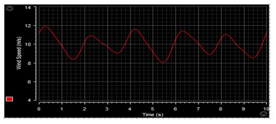
Figure 53.
Wind speed profile.
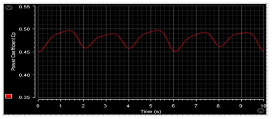
Figure 54.
Power coefficient.
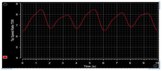
Figure 55.
Tip speed ratio.
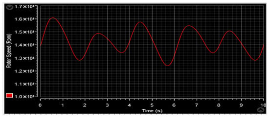
Figure 56.
Mechanical rotor speed.
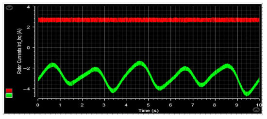
Figure 57.
Quadrature and direct current.
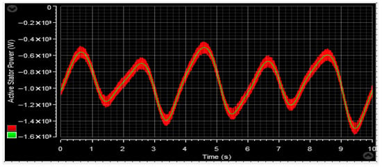
Figure 58.
Stator active power Ps.
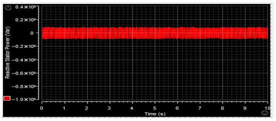
Figure 59.
Stator reactive power Qs.
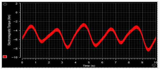
Figure 60.
Developed torque Tem.
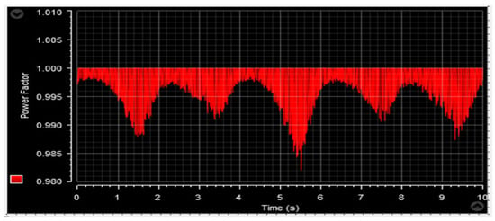
Figure 61.
Power factor.
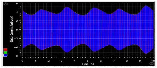
Figure 62.
Stator current isabc.
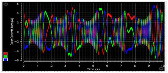
Figure 63.
Rotor current irabc.
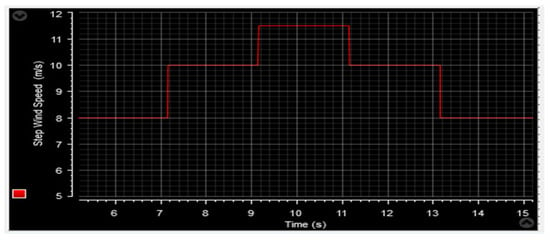
Figure 64.
Step wind speed profile.
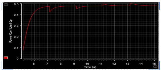
Figure 65.
Power coefficient.
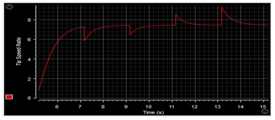
Figure 66.
Tip speed ratio.
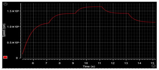
Figure 67.
Rotor speed.
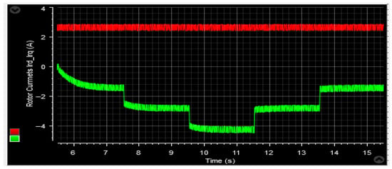
Figure 68.
The d-q rotor currents.
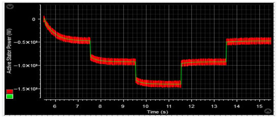
Figure 69.
Active power Ps.
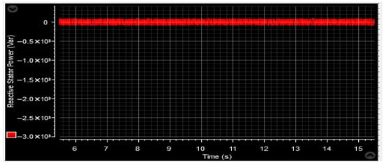
Figure 70.
Reactive power Qs.
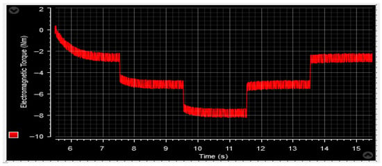
Figure 71.
Developed torque Tem.
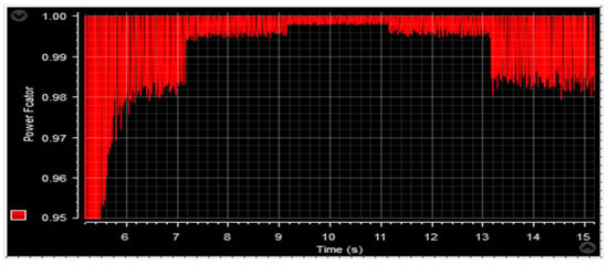
Figure 72.
Power factor.
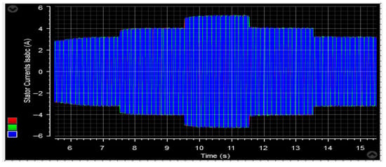
Figure 73.
Stator current isabc.
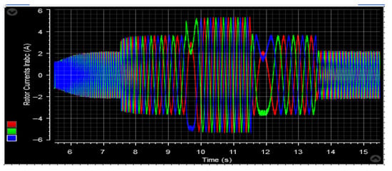
Figure 74.
Rotor current irabc.
The primary test showcases the control performance and tracking affectivity when confronted with fluctuating wind profiles.
An initial observation from these experimental results is the remarkable similarity to the numerical simulation results. The behavior exhibited in the experimental study closely aligns with the findings from the numerical analysis.
Figure 53 and Figure 64 depict the wind speed profiles, while Figure 54 and Figure 65 illustrate the power coefficient in two separate tests. These figures reveal a relationship between the energy value and changes in the wind speed profile. The tip speed ratio (λ) of the wind turbine system (WTS) is presented in Figure 55 and Figure 66, considering both wind speed profiles. These figures demonstrate that the values of λ are emulating the wind speed changes. From these illustrations, it is also observed that the highest and lowest values of λ are 8.24 and 6.90, respectively. Figure 56 and Figure 67 display the rotor speed in the two tests. The rotor speed varies in sync with the wind speed, particularly near the synchronous speed, in both the super-synchronous regime (Ω > 157 rad/s) and the sub-synchronous regime (Ω < 157 rad/s). Notably, the measured rotor speed closely follows the reference speed with minimal response time and no overshoot, affirming the validness of the designed control technique.
Figure 57 and Figure 68 showcase the behavior of the d-q components of the rotor current in the conducted tests. The d-current component, as depicted in these figures, exhibits a reactive power characteristic—consistently maintaining a value of zero. It is worth noting that the duration of the experimental work remains unaffected by variations in wind speed profiles, which exhibit small amplitude ripples. Alternatively, the q-rotor current represents active power and its value fluctuates following the variations in wind speed, accompanied by ripples stemming from the system. These empirical findings serve to validate the results obtained through numerical simulations.
Figure 58 and Figure 69 provide a detailed representation of the active stator power tracking, supported by its mechanical reference. These figures demonstrate the low undulation rate in the power quality of the DFIG.
Furthermore, Figure 59 and Figure 70 depict the reactive power characteristics, specifically highlighting their command value of Qref = 0 VAR. Notably, the reactive power values observed in both tests are relatively low compared to the total generated power.
Moving on to the torque analysis of the DFIG, Figure 60 and Figure 71 showcase the torque profile. It is worth noting that the torque pattern mirrors that of the active power. The torque magnitude varies in response to changes in wind velocity, and the generator exhibits a fast response to alterations in the rated power.
Figure 61 and Figure 72 provide visual representations of the pf characteristics of the DFIG. The pf value depicted in both figures is approximately 0.9998, exhibiting minor fluctuations estimated to be around 0.024%. These fluctuations, attributed to the system, result in faint ripples observed in the figures.
Figure 62, Figure 63, Figure 73 and Figure 74 display the behavior of the currents in the two planned tests. The stator and rotor currents exhibit a sinusoidal pattern, with varying amplitudes based on the wind conditions. Despite fluctuations in the wind profile, the frequency of the stator currents remains constant at fs = 50 Hz. Additionally, the control system demonstrates a quick response to active power changes, effectively adjusting to such fluctuations.
6. Conclusions
In this study, an experimental approach is presented for a DPC topology based on neural networks, specifically applied to a DFIG-based WECS setup. The proposed intelligent strategy utilizes PWM to regulate the Rotor Side Converter of the DFIG, while neural networks are employed to control both the reactive and active power of the DFIG.
Simpleness and ease of implementation are the main benefits of this intelligent control design. To assess its effectiveness, the behavior of the designed intelligent control is compared to three other strategies: classic DPC, backstepping control, and integral sliding-mode control.
The key highlights of this research are as follows:
- The proposed intelligent DPC strategy exhibits superior performance across various wind speed profiles.
- The resilience of the designed intelligent DPC strategy ensures its effectiveness even under wind speed changes.
- The designed ANN-DPC method demonstrates high energy efficiency and power factor, reflecting its efficiency.
- The experimental findings obtained align with the numerical simulation, confirming and validating the characteristics of the intelligent DPC approach.
Furthermore, this work opens up several potential avenues for future exploration, including the following:
- The integration of a storage component and the technical and financial optimization of the WECS.
- Carrying out additional experimental validation on the DFIG-operated wind turbine system.
Author Contributions
Conceptualization, H.C. and M.A.M.; methodology, M.A.M. and H.C.; software, H.C. and M.A.M.; validation, H.C. and M.M.A.; formal analysis, M.M.A. and M.A.M.; investigation, H.C. and M.A.M.; resources, M.A.M.; data curation, H.C. and M.M.A.; writing—original draft preparation, H.C. and M.A.M.; writing—review and editing, M.M.A.; visualization, M.M.A. and H.C.; supervision, M.A.M. All authors have read and agreed to the published version of the manuscript.
Funding
This research received no external funding.
Data Availability Statement
Data are available upon request from the authors.
Conflicts of Interest
The authors declare no conflicts of interest.
Nomenclature
| Variables and Greek letters | |
| β [°] | Pitch angle |
| G | Gearbox ratio |
| Ωt [rad/s] | Speed in turbine shaft side of the gearbox |
| Tm [N.m] | Torque in turbine shaft side of the gearbox |
| f | Total friction coefficient |
| J [Kg.m2] | Inertia moment |
| λ | Ratio of tip speed (TSR) |
| Cp | Coefficient of power |
| ρ [Kg/m3] | Density of the air |
| V [m/s] | Wind velocity |
| R [m] | Blade radius |
| Ωg [rad/s] | Generator’s speed |
| Pt [W] | Power of the turbine |
| p | Pole pairs |
| Ls, Lr, Lf [H] | Stator, rotor, and inductive filter inductances |
| Rs, Rr, Rf [Ω] | Stator, rotor, and inductive filter resistances |
| Lm [H] | Magnetizing inductance |
| Qs [Var], Ps [W] | Reactive and active powers of the stator |
| Tem [N.m] | Electromagnetic torque |
| Irabc [A], Isabc [A] | Rotor and stator currents |
| ϕr [Wb], ϕs | Rotor and stator fluxes |
| Vs, Vr [V] | Stator and rotor voltages |
| ird, irq [A] | Rotor current d-q components |
| ωr, ωs [rad/s] | Rotor and stator pulsations |
| Abbreviations | |
| WECS | Wind energy conversion system (WECS) |
| DFIG | Doubly fed induction generator |
| ANN | Artificial neural network |
| ISMC | Integral sliding-mode controller |
| RSPC | Rotor side power converter |
| GSPC | Grid side power converter |
| THD | Total harmonic distortion |
Appendix A

Table A1.
WECS parameters.
Table A1.
WECS parameters.
| Parameters | Value | Parameters | Value |
|---|---|---|---|
| Number of blades | 3 | Irn (A) | 8.5 |
| Radius R (m) | 1 | p | 2 |
| Gearbox ratio G | 2 | fsn (Hz) | 50 |
| (N·m·s/rad) | 0.0027 | Rs (Ω) | 1.18 |
| (kg·m2) | 0.04 | Rr (Ω) | 1.66 |
| Pn (KW) | 1.5 | Ls (H) | 0.20 |
| Vsn (V) | 220/380 | Lr and Lm (H) | 0.18 and 0.17 |
References
- Lee, J.; Muljadi, E.; Srensen, P.; Kang, Y.C. Releasable Kinetic Energy-Based Inertial Control of a DFIG Wind Power Plant. IEEE Trans. Sustain. Energy 2016, 7, 279–288. [Google Scholar] [CrossRef]
- Fateh, F.; White, W.N.; Gruenbacher, D. A Maximum Power Tracking Technique for Grid Connected DFIG-Based Wind Turbines. IEEE J. Emerg. Sel. Top. Power Electron. 2015, 3, 957–966. [Google Scholar] [CrossRef]
- Chojaa, H.; Derouich, A.; Zamzoum, O.; Mahfoud, S.; Taoussi, M.; Albalawi, H.; Benbouhenni, H.; Mosaad, M.I. A Novel DPC Approach for DFIG-Based Variable Speed Wind Power Systems Using DSpace. IEEE Access 2023, 11, 9493–9510. [Google Scholar] [CrossRef]
- Mossa, M.A.; Echeikh, H.; Iqbal, A. Enhanced control technique for a sensor-less wind driven doubly fed induction generator for energy conversion purpose. Energy Rep. 2021, 7, 5815–5833. [Google Scholar] [CrossRef]
- Habib, B. A comparative study between DTC-NSTMC and DTC-FSTSMC control scheme for a DFIG-based wind turbine. Majlesi J. Energy Manag. 2018, 7, 43–53. [Google Scholar]
- Mossa, M.A.; Do, T.D.; Al-Sumaiti, A.S.; Quynh, N.V.; Diab, A.A.Z. Effective Model Predictive Voltage Control for a Sensorless Doubly Fed Induction Generator. IEEE Can. J. Electr. Comput. Eng. 2021, 44, 50–64. [Google Scholar] [CrossRef]
- Mosaad, M.I.; Sabiha, N.; Abu Siada, A.; Taha, I.B. Application of Superconductors to Suppress Ferro resonance Overvoltage in DFIG-WECS. IEEE Trans. Energy Convers. 2021, 37, 766–777. [Google Scholar] [CrossRef]
- Yousry, I.; Ahmed, R.; Salah, K.; Mohamed, I.M. Performance of PMSG-Wind Power Plant During Three Phase Faults with ANN Based Control of STATCOM. In Proceedings of the IEEE ICA/ACCA 2021, Santiago, Chile, 22–26 March 2021. [Google Scholar]
- Liu, Y.; Guo, G.; Wang, X.; Wang, H.; Wang, L. Sub-Synchronous Oscillation Suppression Strategy Based on Impedance Modeling by Attaching Virtual Resistance Controllers for Doubly-Fed Induction Generator. Electronics 2022, 11, 2272. [Google Scholar] [CrossRef]
- Prasad, R.M.; Mulla, M.A. Mathematical Modeling and Position-Sensorless Algorithm for Stator-Side Field-Oriented Control of Rotor-Tied DFIG in Rotor Flux Reference Frame. IEEE Trans. Energy Convers. 2020, 35, 631–639. [Google Scholar] [CrossRef]
- Ardjal, A.; Bettayeb, M.; Mansouri, R.; Mehiri, A. Nonlinear synergetic control approach for dc-link voltage regulator of wind turbine DFIG connected to the grid. In Proceedings of the 2018 5th International Conference on Renewable Energy: Generation and Applications (ICREGA), Al Ain, United Arab Emirates, 26–28 February 2018; pp. 94–97. [Google Scholar] [CrossRef]
- Bourdoulis, M.K.; Alexandridis, A.T. Direct Power Control of DFIG Wind Systems Based on Nonlinear Modeling and Analysis. IEEE J. Emerg. Sel. Top. Power Electron. 2014, 2, 764–775. [Google Scholar] [CrossRef]
- Benbouhenni, H.; Bizon, N. Improved Rotor Flux and Torque Control Based on the Third-Order Sliding Mode Scheme Applied to the Asynchronous Generator for the Single-Rotor Wind Turbine. Mathematics 2021, 9, 2297. [Google Scholar] [CrossRef]
- Lascu, C.; Boldea, I.; Blaabjerg, F. A modified direct torque control for induction motor sensorless drive. IEEE Trans. Ind. Appl. 2000, 36, 122–130. [Google Scholar] [CrossRef]
- Sahri, Y.; Tamalouzt, S.; LalouniBelaid, S.; Bacha, S.; Ullah, N.; Ahamdi, A.A.A.; Alzaed, A.N. Advanced Fuzzy 12 DTC Control of Doubly Fed Induction Generator for Optimal Power Extraction in Wind Turbine System under Random Wind Conditions. Sustainability 2021, 13, 11593. [Google Scholar] [CrossRef]
- Yousefi-Talouki, A.; Zalzar, S.; Pouresmaeil, E. Direct Power Control of Matrix Converter-Fed DFIG with Fixed Switching Frequency. Sustainability 2019, 11, 2604. [Google Scholar] [CrossRef]
- Mossa, A.M.; Echeikh, H.; Diab, A.A.Z.; Quynh, N.V. Effective Direct Power Control for a Sensor-Less Doubly Fed Induction Generator with a Losses Minimization Criterion. Electronics 2020, 9, 1269. [Google Scholar] [CrossRef]
- Djilali, L.; Badillo-Olvera, A.; Rios, Y.Y.; López-Beltrán, H.; Saihi, L. Neural High Order Sliding Mode Control for Doubly Fed Induction Generator based Wind Turbines. IEEE Lat. Am. Trans. 2022, 20, 223–232. [Google Scholar] [CrossRef]
- Chojaa, H.; Derouich, A.; Taoussi, M.; Chehaidia, S.E.; Zamzoum, O.; Mosaad, M.I.; Alhejji, A.; Yessef, M. Nonlinear Control Strategies for Enhancing the Performance of DFIG-Based WECS under a Real Wind Profile. Energies 2022, 15, 6650. [Google Scholar] [CrossRef]
- Xiong, L.; Li, P.; Li, H.; Wang, J. Sliding Mode Control of DFIG Wind Turbines with a Fast Exponential Reaching Law. Energies 2017, 10, 1788. [Google Scholar] [CrossRef]
- Pura, P.; Iwański, G. Rotor Current Feedback Based Direct Power Control of a Doubly Fed Induction Generator Operating with Unbalanced Grid. Energies 2021, 14, 3289. [Google Scholar] [CrossRef]
- Ahmad, S.; Mekhilef, S.; Mokhlis, H.; Karimi, M.; Pourdaryaei, A.; Ahmed, T.; Jhuma, U.K.; Afzal, S. Fuzzy Logic-Based Direct Power Control Method for PV Inverter of Grid-Tied AC Microgrid without Phase-Locked Loop. Electronics 2021, 10, 3095. [Google Scholar] [CrossRef]
- Cheng, P.; Wu, C.; Ning, F.; He, J. Voltage Modulated DPC Strategy of DFIG Using Extended Power Theory under Unbal-anced Grid Voltage Conditions. Energies 2020, 13, 6077. [Google Scholar] [CrossRef]
- Han, Y.; Ma, R. Adaptive-Gain Second-Order Sliding Mode Direct Power Control for Wind-Turbine-Driven DFIG under Balanced and Unbalanced Grid Voltage. Energies 2019, 12, 3886. [Google Scholar] [CrossRef]
- Mahdhi, H.B.; Azza, H.B.; Jemli, M. Direct Power Control of a PMSG in Wind Power Conversion System under Faulty Rectifier Conditions. In Proceedings of the 2019 19th International Conference on Sciences and Techniques of Automatic Control and Computer Engineering (STA), Sousse, Tunisia, 24–26 March 2019; pp. 394–398. [Google Scholar] [CrossRef]
- Wang, X.; Sun, D.; Zhu, Z.Q. Resonant-Based Backstepping Direct Power Control Strategy for DFIG Under Both Balanced and Unbalanced Grid Conditions. IEEE Trans. Ind. Appl. 2017, 53, 4821–4830. [Google Scholar] [CrossRef]
- Shang, L.; Hu, J. Sliding-Mode-Based Direct Power Control of Grid-Connected Wind-Turbine-Driven Doubly Fed Induction Generators Under Unbalanced Grid Voltage Conditions. IEEE Trans. Energy Convers. 2012, 27, 362–373. [Google Scholar] [CrossRef]
- Pichan, M.; Rastegar, H.; Monfared, M. Fuzzy-based direct power control of doubly fed induction generator-based wind energy conversion systems. In Proceedings of the 2012 2nd International eConference on Computer and Knowledge Engineering (ICCKE), Fujian, China, 21–23 November 2012; pp. 66–70. [Google Scholar] [CrossRef]
- Mohammadi, J.; Vaez-Zadeh, S.; Afsharnia, S.; Daryabeigi, E. A Combined Vector and Direct Power Control for DFIG-Based Wind Turbines. IEEE Trans. Sustain. Energy 2014, 5, 767–775. [Google Scholar] [CrossRef]
- Dzung, P.Q.; Bao, A.N.; Lee, H.H. New artificial neural network based direct virtual torque control and direct power control for DFIG in wind energy systems. In Proceedings of the 2011 IEEE Ninth International Conference on Power Electronics and Drive Systems, Singapore, 5–8 December 2011; pp. 219–227. [Google Scholar] [CrossRef]
- Ngamroo, I. Review of DFIG wind turbine impact on power system dynamic performances. IEEJ Trans. Electr. Electron. Eng. 2017, 12, 301–311. [Google Scholar] [CrossRef]
- Domínguez-García, J.L.; Gomis-Bellmunt, O.; Bianchi, F.D.; Sumper, A. Power oscillation damping supported by wind power: A review. Renew. Sustain. Energy Rev. 2012, 16, 4994–5006. [Google Scholar] [CrossRef]
- Chojaa, H.; Derouich, A.; Taoussi, M.; Zamzoum, O.; Yessef, M. Optimization of DFIG Wind Turbine Power Quality Through Adaptive Fuzzy Control. In Digital Technologies and Applications. ICDTA 2021; Lecture Notes in Networks and Systems; Springer: Cham, Switzerland, 2021; Volume 211. [Google Scholar] [CrossRef]
- Fdaili, M.; Essadki, A.; Nasser, T. Comparative Analysis Between Robust SMC & Conventional PI Controllers Used in WECS Based on DFIG. Int. J. Renew. Energy Res. 2017, 7, 2151–2161. [Google Scholar] [CrossRef]
- Morshed, M.J.; Fekih, A. Integral terminal sliding mode control to provide fault ride-through capability to a grid connected wind turbine driven DFIG. In Proceedings of the IEEE International Conference on Industrial Technology (ICIT), Seville, Spain, 17–19 March 2015; pp. 1059–1064. [Google Scholar] [CrossRef]
- Chojaa, H.; Derouich, A.; Bourkhime, Y.; Chetouani, E.; Meghni, B.; Chehaidia, S.E.; Yessef, M. Comparative Study of MPPT Controllers for a Wind Energy Conversion System. In Lecture Notes on Data Engineering and Communications Technologies; Springer International Publishing: Cham, Switzerland, 2021; Volume 110, pp. 300–310. [Google Scholar]
- Saad, M.M.M.; Mohd, S.; Zulkafli, M.F.; Samiran, N.A.; Didane, D.H. CFD Simulation Study on the Performance of a Mod-ified Ram Air Turbine (RAT) for Power Generation in Aircrafts. Fluids 2021, 6, 391. [Google Scholar] [CrossRef]
- Mensou, S.; Essadki, A.; Nasser, T.; Idrissi, B.B.; Tarla, L.B. Dspace DS1104 implementation of a robust nonlinear controller applied for DFIG driven by wind turbine. Renew. Energy 2020, 147, 1759–1771. [Google Scholar] [CrossRef]
- Ayrira, W.; Ourahoua, M.; El Hassounia, B.; Haddi, A. Direct torque control improvement of a variable speed DFIG based on a fuzzy inference system. Math. Comput. Simul. 2020, 167, 308–324. [Google Scholar] [CrossRef]
Disclaimer/Publisher’s Note: The statements, opinions and data contained in all publications are solely those of the individual author(s) and contributor(s) and not of MDPI and/or the editor(s). MDPI and/or the editor(s) disclaim responsibility for any injury to people or property resulting from any ideas, methods, instructions or products referred to in the content. |
© 2025 by the authors. Licensee MDPI, Basel, Switzerland. This article is an open access article distributed under the terms and conditions of the Creative Commons Attribution (CC BY) license (https://creativecommons.org/licenses/by/4.0/).