Abstract
Hydrogen is a promising alternative fuel for internal combustion engines due to its high specific energy, fast flame speed, and carbon-free combustion. In dual-fuel operation, it offers a practical route to reducing greenhouse gas emissions while remaining compatible with existing engine hardware. This work evaluates how the hydrogen energy substitution ratio (HSR = 50, 70, and 90%) influences spray dynamics, combustion characteristics, and emissions in a heavy-duty compression ignition engine. Simulations are validated against experiments and use a URANS RNG k–ε framework with a hybrid combustion model: the Eddy Dissipation Concept (EDC) coupled with detailed kinetics (111 species, 768 reactions) for auto-ignition and diffusion burning of diesel, and a G-equation for propagation of a hydrogen-rich premixed flame. The results reveal clear spray–combustion linkages. At HSR 50, the higher Weber number induces stronger breakup, yielding a smaller Sauter mean diameter and higher number-averaged droplet velocity; at HSR 90, the spray is more stable and less atomized, with larger droplets and a shorter vapor penetration length. Increasing the HSR reduces unburned hydrocarbons (UHCs) by more than 50% from HSR 50 to HSR 90 while modestly altering combustion phasing (a later CA50 and a shorter burn duration due to faster hydrogen flame propagation). The validated model provides a practical tool for optimizing dual-fuel settings and HSR–EGR–SOI trade-offs to balance efficiency and emissions.
1. Introduction
Rising environmental concerns and the growing need to reduce reliance on fossil fuels have driven intensive research into sustainable energy alternatives, with transportation being the most challenging sector. From an energy supply perspective, the transition toward low- or zero-carbon fuels [1] (such as ammonia [2], hydrogen [3], and methanol [4,5] is critical for reshaping global mobility. Among these, hydrogen stands out as a particularly promising zero-carbon energy carrier because it produces no carbon emissions during combustion. Additionally, it offers advantages such as broad flammability limits, high flame speed [6], short quenching distance [7], high energy density by mass, and high laminar burning velocity [6]. However, hydrogen also presents several challenges: its low energy density by volume complicates storage and transportation; its high flame speed increases the risk of flashback and negatively impacts flame stability (e.g., knock phenomena); and its high diffusivity results in a Lewis number significantly below unity, affecting combustion behavior and heat losses in engines [8]. Knock phenomena can be mitigated using various strategies, such as water injection [9] and retarding ignition timing [10]. Hydrogen is produced through various pathways, such as electrolysis and steam methane reforming, utilizing feedstocks like water, natural gas, and biomass [11,12]. Moreover, green production methods allow for hydrogen generation with zero carbon emissions [13], and its combustion results only in water [14], making it an environmentally friendly fuel [15]. When used in internal combustion engines, hydrogen has the potential to significantly reduce harmful emissions such as carbon dioxide (CO2), particulate matter (PM), and unburned hydrocarbons (UHC) [16]. In fact, adopting a lean combustion strategy can substantially reduce thermal NOx while improving thermal efficiency [17].
Besides a complete transition towards H2-derived fuels in the transport sector, a more cost-effective and reliable short-to medium-term approach to reduce reliance on fossil fuels is the partial substitution of conventional fuels with H2 carriers, commonly known as dual-fuel combustion. Although the dual-fuel approach is not a new concept, it has attracted renewed interest in recent years. Numerous studies have explored dual-fuel combustion with fossil diesel across engine types, using a range of secondary fuels including hydrogen. Hydrogen’s potential in dual fuel engines was first explored through the implementation of a port fuel injection (PFI) system [18]. This approach was primarily motivated by the ease of adapting existing engines, enabling a shorter time-to-market [19,20]. The primary advantage of this method lies in its simple control strategy, along with the ability to achieve an almost fully homogenous mixture [3,21]. Optimizing fuel spray and injection parameters is a key aspect of dual-fuel combustion, as it directly affects atomization, vaporization, mixing, and ultimately combustion efficiency and emissions formation. The concept of variable engine configurations, including variable compression ratio, injection timing, and fuel spray characteristics, is important for optimizing engine performance and emissions [22,23]. In the context of hydrogen dual-fuel combustion, optimizing these parameters helps address challenges related to hydrogen’s high diffusivity and flame speed, ensuring stable and efficient combustion.
Experimental studies have widely reported that the use of hydrogen in combination with diesel in dual-fuel engines enhances thermal efficiency and reduces specific fuel consumption (SFC) as well as emissions of soot (particulate matter), carbon monoxide (CO), and UHC [24,25]. Additionally, this approach generally leads to higher nitrogen oxide (NOx) emissions due to increased combustion temperatures [26,27]. Nevertheless, some studies have reported that NOx emissions may remain unchanged [28] or even decrease [29,30,31], depending on factors such as hydrogen-to-diesel energy ratio and engine load. In particular, some findings suggest that increasing the hydrogen substitution ratio can initially reduce NOx emissions, but beyond a certain threshold, further increases may lead to a rise in NOx formation [32,33]. Furthermore, adjusting the exhaust gas recirculation (EGR) rate to moderate levels has also been found to effectively limit NOx emissions [34,35]. In summary, operating diesel engines in hydrogen–diesel dual-fuel mode can lead to a general reduction in engine-out emissions, including CO2, CO, and UHC, with the notable exception of NOx. NOx emissions are influenced by various engine configuration parameters and combustion control strategies such as EGR [34,36], the hydrogen injection nature (port or direct) [37], engine operating conditions [29,31], the hydrogen substitution ratio [33,38], and the timing of diesel injection [39].
Several numerical studies have been conducted to examine the performance of hydrogen dual-fueled engines. Temizer and Cihan [40] investigated the effects of combustion chamber geometry and hydrogen addition on combustion and emissions using AVL-FIRE simulations. The results showed that adding 5% hydrogen to diesel increased in-cylinder pressure, temperature, flame propagation, and heat release rate. However, it also led to higher NO emissions. Ramsy and Dinesh [41] simulated hydrogen direct injection in a diesel engine ignited by a small diesel pilot injection. The findings showed that at high load, engines running with up to 99% hydrogen demonstrated improved performance and significantly lower carbon emissions. However, at low load, performance dropped sharply because the small diesel pilot struggled to ignite the main hydrogen injection. Cameretti et al. [42] studied diesel–hydrogen dual-fuel combustion using a CFD model validated by experiments. They found that using hydrogen in dual-fuel combustion improves thermal efficiency and significantly reduces carbon emissions while increasing NOx emissions. Vasudev et al. [43] developed an accurate multizone simulation model to evaluate hydrogen addition in RCCI engines, using real operating conditions from a dual-fuel marine engine. The results indicated that hydrogen addition advanced combustion timing and improves indicated thermal efficiency. Bayramoğlu and Yılmaz [44] investigated the effects of hydrogen injection ratios and timings on diesel engine performance at 25% load. Their findings showed that increasing the hydrogen injection ratio and advancing injection timing significantly enhanced engine power, thermal efficiency, and IMEP. The best performance was achieved at an H15 ratio with an injection at −20 CAD. However, these conditions also resulted in higher NOx emissions.
Although hydrogen is widely recognized as a clean and efficient alternative fuel for internal combustion engines, most existing studies concentrate on low hydrogen substitution ratios (typically below 50%) and often overlook the implications of higher substitution levels. There is a lack of detailed studies investigating the effects of elevated hydrogen substitution ratios (HSRs). Furthermore, while hydrogen’s impact on thermal efficiency, engine performance, and emissions has been widely studied, its influence on spray dynamics (such as penetration, atomization and vaporization) remains insufficiently explored. This gap limits the ability to optimize injection strategies and mixture formation in hydrogen assisted dual-fuel combustion engines, particularly under high-HSR conditions. This study addresses this gap in knowledge by analyzing the spray dynamics and combustion performance of a dual-fuel engine operating with high levels of hydrogen substitution (HSR 50, HSR 70, and HSR 90). Computational fluid dynamics (CFD) simulations were conducted using a three-dimensional numerical model of a single-cylinder, four-stroke, dual-fueled compression ignition engine. Simulations were performed using the Unsteady Reynolds-Averaged Navier–Stokes (URANS) methodology.
2. Numerical Setups
2.1. Flow and Combustion Modeling
In this work, CFD simulations were carried out using Ansys Forte 2022 R1 under an academic license, which employs advanced dynamic meshing and detailed chemical kinetics to efficiently model combustion behavior. The flow dynamics were described using an Eulerian–Lagrangian framework, in which the dispersed phase was treated using a Lagrangian approach, while the continuous phase was modeled using an Eulerian formulation. The simulation framework included the conservation equations for mass, momentum, and energy. The conservation of mass is expressed as [45]:
where is the fluid density, is time, and is the velocity. The source term refers to the vaporized fuel quantity. The overbar () indicates Reynolds averaging and the tilde () denotes Favre averaging.
The conservation of momentum is defined as:
where, in the given context, is the in-cylinder pressure, is to the viscous shear stress, and and represent the spray-induced source terms and the specific body force, respectively.
The internal energy transport equation represents the generation and distribution of thermal energy during the combustion process. It is expressed as:
where, , , and , are the Internal energy, the pressure and the derivative of the total heat flux from enthalpy diffusion and heat conduction, respectively. The quantities and represent the source terms due to chemical heat release (production rate) and the spray interactions, respectively. H accounts for the effects of filtered convection term, while denotes the dissipation rate.
Turbulence was modeled via the URANS RNG - model, which is well-suited for capturing strained flow characteristics. It was developed using the Re-Normalization Group (RNG) method. This model addresses the transport equations of Reynolds stress and eliminates the constraints associated with the eddy-viscosity hypothesis. The RNG k-ε model is expected to perform better, especially in swirling flows [25]. The turbulent kinetic energy () and its dissipation rate () are governed by Equations (4) and (5), respectively:
where represents the turbulent kinetic energy, and ∇.() denotes the rate of change of kinetic energy per unit mass due to convection. refers to the Reynolds stress tensor. The turbulent viscosity is expressed as μt. denotes the turbulent Prandtl number. The term represents the source term. The source terms involving were determined using the droplet probability distribution function. Physically, corresponds to the negative rate at which turbulent eddies are expended to disperse the spray droplets. is the dissipation rate and denotes the unsteady accumulation term. The model constants are given in Table 1.

Table 1.
The constant of RNG k-ɛ model [45].
The flame propagation model simulated the development of the ignition kernel using the discrete particle ignition kernel flame model proposed by Tan and Reitz [46]. The flame front, represented as a spherical kernel, was tracked using Lagrangian particles, and the flame surface density was calculated based on the local concentration of these particles within each computational cell. In the kernel growth stage, chemical reactions were modeled using a method consistent with the principles of the G-equation combustion model. A power-law correlation was employed to relate the laminar flame speed with pressure, temperature, and equivalence ratio. This method followed the Gülder formulation for estimating laminar flame speed [47]. The Gülder formulation was derived and validated based on a wide range of experimental flame propagation data obtained from internal combustion engine studies [48]. The Equation of the laminar flame speed (6) is given by:
where the constants , , , and are empirical fitting coefficients derived from experimental data in [47,48]. After auto-ignition occurs, the flame front propagated outward, and the flame-turbulence interactions were solved through the RNG k-ε transport equations. This resulted in the formation of a turbulent flame, with its propagation speed governed by several parameters. The evolution of the local turbulent flame was modeled using the G-equation, which directly correlates with the laminar flame speed. The laminar flame speed is, in turn, a key chemical property of the gas mixture. The G-equation combustion model is based on the turbulent premixed combustion theory by Peters [49]. This theory outlines two regimes of practical significance. The first is the corrugated flamelet regime, in which the entire reactive-diffusive flame structure is assumed to be embedded within eddies at the Kolmogorov length scale (). The second regime is the thin reaction zone regime, where Kolmogorov eddies can penetrate the chemically inert preheated zone of the reactive-diffusive flame structure but cannot reach the inner layer where the chemical reactions occur. For this application of the G-equation model to internal combustion engines, this theory was further developed and validated by Tan and Reitz [46] and Liang and Reitz [50].
The G-equation model [49,50,51,52] simulates in-cylinder turbulent flame propagation by excluding chemical source terms from the transport equations [53]. In this model, the G term represents the scalar distance between the instantaneous flame front and its mean position [49]. Using Equations (7) and (8), along with the Favre averaging (density-weighted) method, the model determines the flame front location and estimates the flame brush thickness.
In these equations, and are the fluid and moving vertex velocity, respectively, and and are the average densities for unburned and burned gas, respectively. is the turbulent flame speed. refers to the turbulent diffusivity. is the tangential operator. is the sum of Favre kinematic restoration and Favre scalar dissipation (i.e., the dominant term in corrugated flamelets regime and the dominant term in thin reaction zones regimes) [49]. and are the Favre mean turbulence kinetic energy and its dissipation rate from RNG k- model [54]. is a modeling constant derived from spectral closure [50], and is the Favre mean flame front curvature, defined in Equation (9) [50]:
To solve the G-equation model, it is necessary to estimate the turbulent flame speed. The unsteady flame speed is calculated based on the mean gradient (Equation (10)), which represents the ratio of flame surface area:
where represents a progress variable, and and refer to the turbulence integral length scale and the laminar flame thickness, respectively. The constants , , and are general for any turbulent flame and were calibrated by Peters [49] through fitting experimental data. is the turbulence velocity. The progress variable is given by Equation (11):
The term , which increases exponentially, accounting for the influence of ignition kernel turbulence on early flame growth (i.e., during the transition from laminar to turbulent flame). A value of equal to one indicates a fully developed turbulent flame. The flame development coefficient , derived from the model constant , is used in the simulations to reduce modeling uncertainties, particularly mesh sensitivity.
The turbulent flame brush thickness , is derived from Equation (8):
where is a dimensionless constant, determined through dimensional analysis, and has a value of 1.78.
The G-equation, combined with the Unsteady Reynolds-Averaged Navier–Stokes (URANS) equations and the Re-normalized Group (RNG) k- turbulence model, forms a closed system that fully characterizes turbulent flame propagation. The resulting flame front data was subsequently used to compute in-cylinder heat release, end-gas kinetics, and emissions formation.
The simulations adopted Prandtl and Schmidt number of 0.74 and 0.56, respectively. These parameters was used to convert dynamic viscosity into thermal diffusivity and mass diffusivity for turbulent flow transport calculation. The same values were used in a previous study [4]. The Prandtl number reflects the ratio of the momentum diffusivity to thermal diffusivity, influencing the heat transfer behavior. The Schmidt number characterizes the ratio of momentum diffusivity to mass diffusivity, affecting species transport.
The Kelvin–Helmholtz/Rayleigh–Taylor (KH-RT) breakup model and the Discrete Multi-Component (DMC) vaporization model were employed to simulate spray dynamics. In this framework, the KH-RT model governs the atomization and droplet breakup processes of the solid-cone fuel spray. The KH model was used to estimate the initial breakup length of the liquid jet, while the RT model accounted for the secondary breakup of droplets occurring beyond this length [33]. The hybrid model is widely used for solid-cone spray breakup due to its effectiveness in capturing both primary and secondary breakup mechanisms. Park et al. [55] reported that the KH-RT model accurately describes the influence of fuel and ambient gas temperatures on spray behavior. Spray vaporization was modeled using the DMC approach, which tracks the behavior of individual fuel droplets during evaporation and enables interaction with the chemical kinetics of each fuel component. This model assumes a spherical shape for the liquid fuel droplet and focuses solely on the physical aspects of cold flow, excluding any chemical reaction effects [34]. For the present study, the estimated fuel spray angle was 12°. It is incorporated into the model using an aerodynamic approach based on Taylor’s analysis of high-speed liquid breakup caused by unstable growth of surface waves and the resulting mass shedding. In this approach, the spray angle is expressed as (13):
where
and L/D is the length-to-diameter ratio of the nozzle. The function is approximated as:
with
A = 3 + 0.28(L/D)
Here, and are the Reynolds and Weber numbers, while and denote the liquid and gas densities, respectively.
The chemical kinetics were modeled using a detailed reaction mechanism that combines heptane and hydrogen, consisting of 111 species and 768 reactions, obtained from the ANSYS Model Fuel Library [52]. The mechanism provides validation data for simulating multi-component fuel combustion [56], including hydrogen–diesel interactions [44]. Heptane (C7H16) was employed as a surrogate for diesel fuel, while the spray’s physical properties were modeled using hexadecane (C16H34).
2.2. Computational Domain
The CFD model was developed based on a single-cylinder, four-stroke compression-ignition engine. The engine speed was set to 1600 rpm for the simulation. The computational domain is represented in Figure 1. Only a 45° sector mesh was used. A mesh sensitivity analysis was performed to verify grid independence. The simulations started from the intake valve closing at 140 CAD BTDC and continued until the exhaust valve opening at 130 CAD ATDC, in order to capture the complete closed-cycle in-cylinder processes. This interval includes the compression, combustion, and expansion strokes, which are critical for accurately modeling ignition delay, flame development, heat release, and in-cylinder pressure evolution. Ending the simulation at the exhaust valve opening ensures that the effects of combustion completion and exhaust blowdown are fully captured. This, in turn, enhances the accuracy of predictions related to engine performance, thermal efficiency, and emission characteristics. The boundary and initial conditions applied are listed in Table 2. The in-cylinder pressure was obtained from experimental measurements, while the in-cylinder gas temperature was assumed to be equal to the cylinder wall temperature due to the absence of experimental in-cylinder temperature at IVC. Other initial and boundary conditions were selected based on values commonly reported in previous studies.
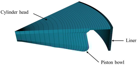
Figure 1.
3D simulation model at 3° BTDC.
Table 2.
Initial and boundary conditions.
The hydrogen substitution ratio (HSR) refers to the proportion of total energy supplied by hydrogen during a cycle. It is given according to Equation (17) [57]:
where refers to the diesel mass flow rate (kg/h), represents the measured hydrogen mass flow rate (kg/h), stands for the diesel lower heating value (MJ/kg), and denotes the hydrogen lower heating value.
2.3. Mesh Independency
To ensure consistency and assess numerical accuracy, the mesh independency analyses were conducted under defined operating conditions, including an engine speed of 1600 rpm and an IMEP of 5.2 bar. Three mesh configurations were used to evaluate the influence of element size on both result accuracy and computational efficiency. Figure 2 presents the mesh structures at top dead center (TDC). The simulation results were compared with experimental data to validate the numerical approach.

Figure 2.
Mesh grid resolution at 3 CAD BTDC: (a) 25,000 cells, (b) 50,000 cells, (c) 100,000 cells.
The meshes consisting of 25,000 and 50,000 cells provided a balanced trade-off between accuracy and computational efficiency. A summary of the mesh independence analysis is presented in Table 3.
Table 3.
Mesh independence study results.
Figure 3 illustrates the effect of mesh resolution on the simulated in-cylinder pressure as a function of crank angle, compared with experimental data at HSR 50. The results show that the pressure profiles obtained with all three mesh sizes are very similar, with each case accurately reproducing the experimental trend. Although the 100,000-cell mesh showed slightly better resolution, the improvement was marginal compared with the 50,000-cell mesh, justifying the computational efficiency trade-off. The negligible variation between simulated curves confirms that the model is effectively independent of mesh size within the examined range. This finding indicates that the use of finer meshes does not yield any significant improvement in accuracy and only increases computational cost. Consequently, the mesh with 50,000 cells was selected as it provides an optimal balance between computational cost and numerical accuracy.
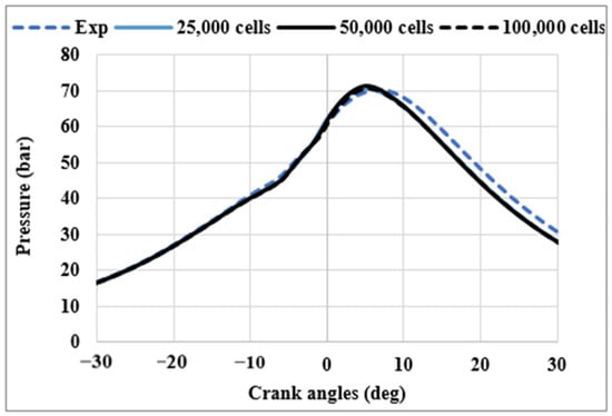
Figure 3.
Impact of mesh resolution on in-cylinder pressure, compared with experimental data for HSR 50.
3. Validation
In this work, three representative cases were selected to investigate the impact of hydrogen energy ratio on dual-fuel combustion characteristics. The selected hydrogen substitution ratios (HSRs) were HSR 50, HSR 70, and HSR 90. These cases were validated to ensure both numerical accuracy and consistency with experimental trends. The objective was to analyze the influence of HSR on spray dynamics, flame development, reaction zone characteristics, and combustion emissions. The numerical model was validated against experimental data provided by Domínguez et al. [34]. Model validation was carried out using experimental data obtained from tests conducted on a single-cylinder compression ignition AVL 580 engine. The engine operated with a compression ratio of 15.84:1, with an independent control system managing the intake and exhaust pressure. Table 4 outlines more details about the engine specifications. Diesel fuel injection was performed through two primary events: a pilot injection delivering 15% of the total fuel mass, followed by the main injection constituting the remaining 85%. Both injection events used a common rail system operating at 600 bar. Hydrogen was introduced into the intake manifold using a port fuel injection system at a pressure of 5 bar. The experiments were conducted at an engine speed of 1600 rpm under low-load conditions (25% of the engine’s full load capacity), with an indicated mean effective pressure of 5.2 bar. These operating conditions, also used by other researchers [38], correspond to one of the 13-mode test points specified for medium-duty trucks, in accordance with UNECE regulation No. 4.
Table 4.
Engine parameters.
The experimental procedure was structured in three phases. Phase 1 was an exploratory study conducted at low and high loads under conventional diesel combustion (CDC) and HSR 35 to evaluate the effects of seven operating variables, identify maximum and minimum indicated thermal efficiency and NOx for the objective function (OF), and assess whether hydrogen dual-fuel operation could surpass CDC performance. A fractional factorial design ensured that the influence of all variables was determined with 95% confidence. Phase 2 focused on optimizing the OF for selected HSR values using a second order Response Surface Method (RSM), considering the most significant operating variables identified in Phase 1, and including HSR as an independent variable if dual-fuel operation showed improvement. Phase 3 explored higher HSR values in 10–20% steps to determine the maximum hydrogen substitution achievable, while ensuring that operating variables remained near previously optimized values to maintain safe and stable engine operation. Table 5 presents the operating conditions corresponding to the various hydrogen substitution ratios. Hydrogen substitution ratios of 50%, 70%, and 90% were selected. According to Domínguez et al. [38,58], the operating conditions provided in Table 5 are those that optimize engine performance and pollutant emissions.
Table 5.
Operating parameters for various HSRs.
Figure 4 presents the variation of in-cylinder pressure and heat release rate as a function of crank angle. The numerical results show good agreement with experimental measurements, validating the accuracy of the physical model. Overall, the results indicate that the model accurately predicts combustion behavior, with the maximum pressure well captured across all HSRs. As HSR increases, the HRR peaks become sharper and shift slightly in crank angle, indicating changes in ignition timing. Specifically, the peak pressure and heat release are delayed at HSR 90. This variation can be attributed to the diesel injection strategy, since at HSR 90 there is no pilot diesel injection. With 50% and 70% hydrogen substitution, the apparent heat release rate (HRR) exhibits three distinct peaks. The first peak corresponds to the combustion of the pilot injection, the second to the premixed combustion phase, and the third to the diffusion combustion phase. However, it is difficult to clearly distinguish between the second and third peaks in the experimental HRR curve, whereas they are much more distinct in the numerical results. At HSR 90, most of the hydrogen burns in the form of turbulent flames that propagate throughout the chamber from the ignition points of the diesel fuel, overlapping with one another [59].
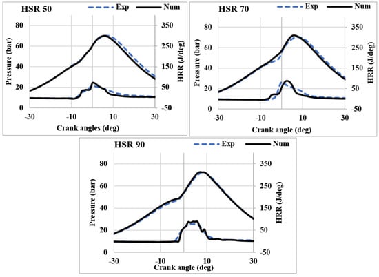
Figure 4.
Model validation: in-cylinder pressure and HRR.
As shown in Figure 4, the agreement between CFD predictions and experimental measurements improves with increasing hydrogen substitution. This behavior can be attributed to hydrogen’s faster chemical kinetics, higher flame speed, and greater diffusivity, which make the combustion process more reaction-rate dominated rather than mixing-limited. Consequently, the selected chemical kinetic mechanism more accurately capture key combustion characteristics, including ignition delay, combustion phasing at higher HSRs.
The effect of HSR on ignition delay, combustion duration, and combustion phasing is presented in Figure 5. The ignition delay is defined as the time interval between the start of injection and the onset of combustion, with ignition identified as the point at which 10% of the total fuel mass has burned.
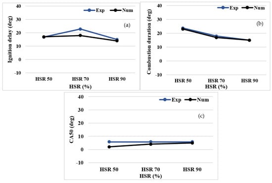
Figure 5.
Effect of HSR on: (a) ignition delay, (b) combustion duration, and (c) CA 50.
Figure 5a illustrates the impact of HSR on ignition delay, comparing both experimental and numerical results. A non-linear correlation is observed between the ignition delay and HSR. The ignition delay increases from HSR 50 to HSR 70, reaching a maximum at HSR 70, before decreasing at HSR 90. At HSR 70, the experimental ignition delay is longer because the pilot injection of the diesel fails to ignite, as shown by the experimental HRR curve (Figure 4). In contrast, the numerical model predicts a slightly shorter ignition delay at HSR 70, because the pilot diesel ignites in the simulation, as indicated by the numerical HRR (Figure 4). Notably, the numerical and experimental ignition delays match closely at HSR 50 and 90. This discrepancy at HSR 70 may arise from complexities in the transition from diesel-dominated to hydrogen-assisted ignition that are not fully captured by the model, or from differences in the physicochemical properties of the modeled diesel fuel and the diesel used experimentally. At HSR 90, a shorter ignition delay was observed. This behavior is primarily driven by the increased hydrogen content in the heptane mixture, which enhances the reactivity of the fuel-air mixture [36]. The presence of hydrogen, known for its exceptionally low ignition energy [60], promotes earlier auto-ignition, thereby accelerating the combustion process. As a result, the ignition delay is reduced compared with cases with lower hydrogen substitution.
Figure 5b shows the evolution of combustion duration, defined as the time interval between 10% and 90% of the fuel mass being burned, for varying HSRs. Both experimental and numerical results show a consistent decreasing trend in combustion duration as the HSR increases. The introduction of hydrogen into the fuel mixture increases both laminar flame speed and diffusivity, which in turn accelerates the combustion process. As a result, the combustion duration is reduced. In addition, the turbulence intensity and ratio are slightly influenced by the hydrogen fraction. An increase in the hydrogen ratio leads to higher turbulence intensity [61], which enhances mixing thereby further reduces combustion duration. A similar trend was observed at high HSR under high load conditions [62].
CA50 represents the crank angle position where 50% of the fuel mass is burned. This parameter plays a key role in the efficiency of internal combustion engines. An advanced CA50 results in higher peak in-cylinder pressure and enhanced thermal efficiency due to more complete combustion occurring closer to top dead center. In contrast, a significantly delayed CA50 reduces combustion temperature and pressure, thereby lowering NOx emissions but potentially compromising overall engine efficiency. It is widely used as a control indicator to optimize combustion, with the goal of improving engine performance. Figure 5c shows that an increase in the HSR results in a delayed CA50. The experimental CA50 values are consistently around 5 CAD after the top dead center, suggesting stable combustion phasing. In contrast, the numerical simulation underestimates CA50 at HSR 50, with a value of 2 CAD. However, as HSR increases, the numerical predictions converge toward alignment with the experimental results at higher hydrogen substitution.
Figure 6 shows the variations in Indicated Thermal Efficiency (ITE). At HSR 50, the numerical model underpredicts thermal efficiency compared with the experimental value (38% predicted versus 45% measured). However, at HSR 90, the numerical prediction agrees closely with experimental data, with both values near 43%. This convergence suggests that the model captures combustion behavior and thermal processes at higher HSRs, possibly because the combustion characteristics become more dominated by hydrogen, which the model represents more accurately.
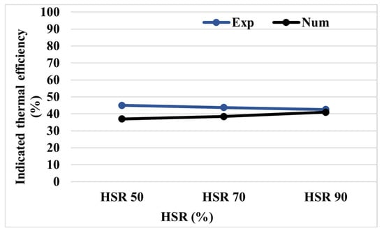
Figure 6.
The effect of HSR on Indicated Thermal Efficiency.
4. Results and Discussion
4.1. Spray Dynamics
Figure 7 provides a comprehensive overview of spray dynamics and vaporization behavior under varying HSRs. It highlights the evolution of vapor mass and penetration length, droplets size (SMD), breakup process (characterized by Weber number), and droplets velocity. These parameters offer detailed insights into the impact of hydrogen on spray structure and combustion-relevant characteristics.
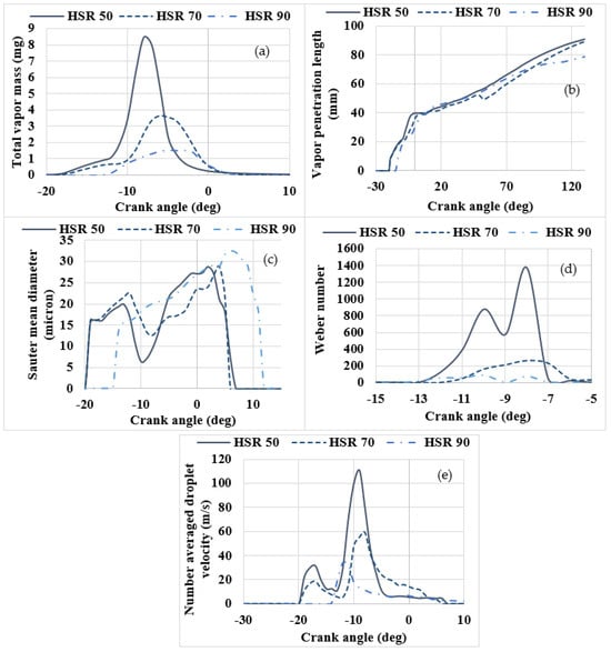
Figure 7.
Spray dynamics and vaporization behavior: (a) vapor mass, (b) vapor penetration length, (c) Sauter Mean Diameter, (d) Weber number, and (e) Number averaged droplets velocity.
As shown in Figure 7a, increasing the HSR leads to a notable reduction in the total vapor mass. The maximum vapor mass occurs at approximately −8 CAD for HSR 50 and −5.9 CAD for HSR 70, with HSR 50 exhibiting the sharpest and highest peak. This peak significantly decreases and becomes broader as the hydrogen content increases, particularly at HSR 90. The sharp and higher peak at lower HSR (HSR 50) reflects a greater accumulation of vaporized fuel before ignition, likely due to the higher mass of injected diesel. In contrast, the flatter and lower peaks at HSR 70 and HSR 90 indicate that the reduced diesel quantity, combined with hydrogen addition, prolongs the vaporization process. Moreover, the flatter peaks indicate delayed combustion phasing, as combustion progresses more smoothly over a wider crank angle range.
Figure 7b illustrates the variation of vapor penetration length with crank angle. Vapor penetration length is defined as the distance from the injector nozzle to the point where 99.9% of the total liquid mass has vaporized. It is calculated by accumulating the mass of fuel vapor in cells, starting from the nozzle exit [4]. A shorter vapor penetration enhances droplet vaporization. All cases show a continuous increase in penetration following the start of injection, but a slight reduction is observed with increasing HSR. HSR 50 shows the longest penetration length, particularly beyond 60° CA, whereas HSR 90 exhibits the shortest. This behavior can be explained by the decreased particle velocity due to reduced injection mass (Figure 7e), which limits further spray development.
The Sauter Mean Diameter (SMD) represents the ratio of average droplet volume to the average surface area across the entire droplet size distribution range. It serves as a key indicator of spray quality; smaller SMD values correspond to finer atomization. Finer atomization facilitates fuel vaporization and promotes more efficient fuel-air mixing. The SMD plot (Figure 7c) shows smaller droplets at earlier crank angles for all HSRs, with a rising trend toward TDC. Notably, HSR 90 produces larger SMD values, indicating lower atomization and slower vaporization. The reduced vaporization rate of diesel at high HSRs stems from the significantly lower volumetric energy density of hydrogen (5.6 MJ/L) compared to diesel (35.8 MJ/L), despite hydrogen high specific energy by mass (120.83 MJ/kg) [34]. As more hydrogen is introduced, the thermal energy available in the spray environment diminishes, reducing heat transfer to the diesel droplets. This results in a slower vaporization process. In contrast, HSR 50 maintains smaller SMD, indicating improved atomization and more efficient vaporization. This enhancement is due to the lower proportion of hydrogen, which allows for a higher diesel content and thus promotes effective droplet breakup due to increased liquid momentum. However, as the diesel quantity decreases with higher hydrogen substitution, the droplet velocity (Figure 7e) and the resulting shear interaction with the surrounding air also decrease. The properties of the environment surrounding diesel droplets (ambient temperature, pressure, flow velocity) along with fuel characteristics (such as droplet size) are the primary factors governing droplet evaporation and spray behavior [63].
The Weber number quantifies the balance between inertial forces and surface tension forces. It provides insight into whether the droplets retain their integrity or break up, thereby influencing atomization and mixing quality. As shown in Figure 7d, the Weber number increases after the start of injection for all HSR cases, indicating that inertial forces become more dominant as the spray develops. The highest Weber number is observed at HSR 50, reflecting stronger inertial effects that enhance droplet breakup. Conversely, the lowest Weber number is observed at HSR 90, confirming a reduced particle velocity resulting from lower injected mass. This behavior is consistent with the larger SMD, shorter vapor penetration and decreased particle velocity observed at higher HSRs.
The droplet velocity profile, presented in Figure 7e, peaks approximately in the same region as the vapor mass (~10° CA), with HSR 50 showing the highest velocity. This supports the higher Weber number at HSR 50. As HSR increases, droplet velocity decreases, indicating lower momentum due to the lower injected fuel mass.
4.2. Combustion Pattern
Figure 8 presents the evolution of OH mass fraction and temperature distribution at three crank angles for different HSRs. The spray controls the onset of combustion in all three HSR configurations. This behavior confirms that, even under dual-fuel operation, the pilot fuel governs the initial flame development, in agreement with Zou et al. [64]. At HSR 50 (2–12 CAD ATDC), OH radicals form within the spray plume, initially appearing near the nozzle and progressively extending toward the cylinder wall. As HSR increases from 70 to 90, the highest OH concentration remains localized near the nozzle region along the piston bowl wall. This high-reactivity zone is surrounded by a lower-concentration OH region that expands more broadly, covering almost the entire cylinder area at 12 CAD ATDC. The highest OH concentration corresponds to the reaction zones, which are typically associated with fuel-rich regions. The observed OH reduction in these zones is attributed to the lower diesel content resulting from increased hydrogen substitution.
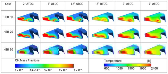
Figure 8.
In-cylinder OH radicals and temperature distribution at different hydrogen substitutions.
This trend is further confirmed by equivalence ratio contours (Figure 9), which show that rich regions initially form near the cylinder walls as the diesel penetrates and reaches them. This behavior is supported by the droplet velocity curves, which show the highest velocity at HSR 50, gradually decreasing as HSR increases. At HSR 90, the rich region is primarily observed near the nozzle, as the reduced diesel quantity and lower droplet velocity prevent the spray from reaching the cylinder walls. In all cases, the fuel-rich zones are followed by stoichiometric regions, indicating effective mixing between the fuels and the surrounding air. In contrast, the lower-concentration OH regions become more uniform and are primarily governed by the presence of hydrogen, as depicted in Figure 9. This behavior stems from hydrogen’s higher diffusivity and faster flame speed, which enhance combustion reactions and promote faster and more homogeneous flame propagation. Furthermore, the temperature maps align closely with the OH regions, confirming that early heat release arises from pilot-fuel radicals (Figure 8). At HSR 50, the high temperature region tends to extend toward the cylinder walls, whereas at HSR 90, it shifts toward the piston bowl wall. These observations are consistent with the findings of Zhang et al. [65], who reported similar temperature distribution patterns under varying hydrogen substitution levels. HSR 50 and HSR 70 produce intense and localized hot regions (≈2400 K) with sharp temperature gradients that accelerate flame propagation. In contrast, HSR 90 produces a broader and less intense temperature peak (≈1600–2000 K) and a larger reaction zone, leading to more distributed combustion. Similar findings were reported by Leng et al. [66], who investigated the effects of hydrogen enrichment on the combustion and emission characteristics of a turbulent jet ignited medium speed natural gas engine in a numerical study. The temperature contours showed that as the hydrogen content increases, high-temperature regions expand throughout the cylinder.
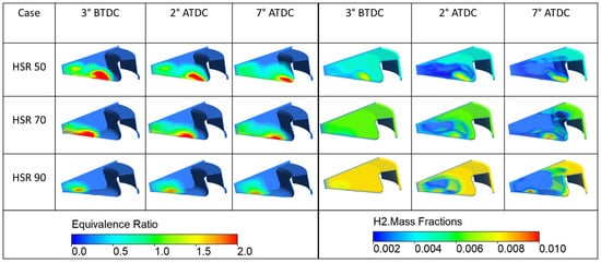
Figure 9.
Equivalence ratio and hydrogen mass fractions distribution at different hydrogen substitutions.
4.3. Effect of Hydrogen Substitution on Emissions
Hydrogen substitution in diesel combustion enhances flame propagation speed and raises the adiabatic flame temperature, both of which significantly influence emissions formation. Figure 10 presents the variation of NOx and UHC emissions for different hydrogen substitution ratios. Nitrogen oxides (NOx) formed during combustion are primarily composed of nitric oxide (NO) and nitrogen dioxide (NO2), with NO typically accounting for 90–95% and NO2 for 5–10% [67]. NOx formations are strongly influenced by the in-cylinder temperature [40]. As the HSR increases from 50 to 90, NOx emissions rise (Figure 10a). The observed increase in NOx emissions is primarily driven by the elevated adiabatic flame temperature of hydrogen [41]. This trend has been observed in previous works [68,69,70]. Experimentally, Exhaust Gas Recirculation (EGR) was strategically increased at higher HSRs to effectively reduce NOx emissions by lowering the oxygen concentration and peak flame temperature. The discrepancy between simulated and experimental NOx values stems from the simplified assumption of a spatially uniform EGR distribution in simulations, whereas the experiments involve a stratified EGR configuration. This modeling simplification leads to a consistent overprediction of numerical NOx emissions at higher hydrogen substitution levels.
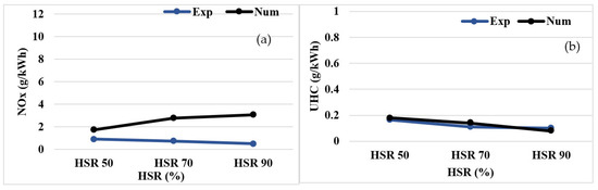
Figure 10.
The effects of HSR on emissions: (a) NOx and (b) UHC emissions.
Figure 10b illustrates the variation in UHC emissions as a function of HSR, comparing both experimental and numerical results. Hydrocarbons in this context refer to all compounds that contain hydrogen and carbon atoms in non-zero amounts, even if oxygen is also present. The model accurately reproduces UHC emissions relative to the experiments. When the HSR increases, the unburned hydrocarbon emissions decrease. When the HSR increases from 50 to 70, UHC emissions decrease by approximately 22%. Beyond HSR 70 the reduction rate slows. This trend is explained by three main factors. First, as HSR increases, the amount of hydrocarbon fuel decreases, which directly reduces UHC. Second, the addition of hydrogen enhances the reactivity of the fuel-air mixture, making it easier for the fuel to ignite and burn more completely, further reducing UHC emissions. Finally, hydrogen’s smaller flame quenching distance [7] helps sustain combustion at lower temperatures, ensuring that more fuel is consumed and preventing the formation of unburned hydrocarbons. Similar behavior was reported by Guo et al. [71] for a natural gas–diesel dual-fuel engine.
5. Conclusions
This study investigates the effects of hydrogen substitution ratios in a compression ignition engine operating in dual-fuel mode, where diesel serves as the pilot fuel. The investigation relies on numerical simulations carried out with an Eulerian–Lagrangian multiphase flow approach, a detailed reaction mechanism, and the Eddy Dissipation Concept coupled with the RNG turbulence model. The results were validated against experimental data. Through this approach, this study offers a comprehensive analysis of the effects of varying hydrogen substitution ratios on key combustion parameters, such as spray dynamics, combustion characteristics, emissions, and engine performance. The key findings are summarized as follows:
- The numerical model developed in this study demonstrates good agreement with experimental results, particularly in capturing combustion behavior across varying HSRs. Although minor discrepancies exist in some parameters, the overall predictive capability of the model remains robust. It effectively reproduces key features such as in-cylinder pressure and HRR, combustion phasing, and emissions trends. These results support the model’s reliability as a tool for analyzing hydrogen-fueled dual-fuel engines.
- The highest Weber number at HSR 50 indicates stronger inertial effects and enhanced droplet breakup, while the lower Weber number at HSR 90 indicates more stable droplets due to reduced fuel injection quantity. This trend, along with a larger SMD, shorter vapor penetration, and decreased particle velocity at higher HSRs (70 HSR 90), highlights reduced atomization efficiency.
- At HSR 50, the reaction zone forms within the spray plume, initiating near the nozzle and progressively extending toward the cylinder wall. As HSR increases from 70 to 90, the reaction zone becomes more localized near the nozzle region along the piston bowl wall.
- Increasing HSR shortens ignition delay and combustion duration due to hydrogen’s high diffusivity.
- A significant reduction in UHC emissions was observed with elevated hydrogen levels. This is due to hydrogen’s carbon-free composition, improved mixture reactivity, and lower flame quenching distance, which promote more efficient combustion. In contrast, NOx emissions increase, as the higher thermal environment from hydrogen addition favors NOx formation.
This study demonstrates that increasing hydrogen substitution ratios in diesel engines significantly reduces combustion duration and UHC emissions. However, NOx emissions rise with HSR due to higher flame temperatures, suggesting the need for advanced aftertreatment systems or EGR strategies. The validated CFD model reliably captures these trends and can be extended for parametric optimization in hydrogen–diesel dual-fuel strategies.
For future research, investigations should be extended to cover a wide range of equivalence ratios and higher engine loads to better assess the robustness of hydrogen substitution strategies under more demanding operating conditions. Such studies would provide further insight into optimizing efficiency–emissions trade-offs and enhancing the applicability of hydrogen–diesel dual-fuel combustion in practical engines.
Author Contributions
Data curation, V.M.D. and J.R.-F.; Methodology, F.H., J.J.H. and M.C.; Supervision, J.J.H. and M.C.; Validation, M.C.; Visualization, S.M.; Writing—original draft, T.H.; Writing—review and editing, T.H., F.H., J.J.H. and M.C. All authors have read and agreed to the published version of the manuscript.
Funding
The experimental data used in this work were obtained under the project PID2022-142004OB-I00, financed by MCIN/AEI/10.13039/501100011033/FEDER, UE “Una manera de hacer Europa”, as well as Junta de Comunidades de Castilla-La Mancha through the ETINVI research project (ref: SBPLY/21/180501/000051, also with the participation of the European Regional Development Fund).
Data Availability Statement
The data that support the findings of this study are available from the corresponding author upon reasonable request.
Conflicts of Interest
The authors declare no conflicts of interest.
References
- Khan, M.A.; Onwuemezie, L.; Gohari Darabkhani, H. Low-carbon fuelled MGT-CHP system coupled with PEM electrolyser and fuel cell units: A fuel flexibility and performance study. Int. J. Hydrogen Energy 2024, 58, 1277–1283. [Google Scholar] [CrossRef]
- Molima, S.; Hamdi, F.; Hamdi, T.; Trudon, G.; Mondo, K.; Amsini, S.; Chrigui, M. Effects of H2 substitution on combustion and emissions in ammonia / diesel compression ignition engine. Energy Convers. Manag. 2025, 334, 119858. [Google Scholar] [CrossRef]
- Millo, F.; Pucillo, F.; Piano, A.; Giordana, S.; Rapetto, N.; Schauette, C. Experimental investigation on the optimal injection and combustion phasing for a direct injection hydrogen-fueled internal combustion engine for heavy-duty applications. Int. J. Hydrogen Energy 2023, 100, 398–406. [Google Scholar] [CrossRef]
- Hamdi, T.; Hamdi, F.; Molima, S.; Hernandez, J.J.; Chrigui, M. Computational Analysis on the Effect of Methanol Energy Ratio on the Spray and Combustion Pattern of a Dual-Fuel Compression Ignition Engine. J. Energy Resour. Technol. Part A Sustain. Renew. Energy 2025, 1, 042303. [Google Scholar] [CrossRef]
- Liu, S.; Deng, Y.; Wang, W.; Yang, L.; Du, X. Performance enhancement of solar heat transfer oil driven methanol steam reforming printed circuit microreactor. Int. J. Hydrogen Energy 2024, 94, 97–112. [Google Scholar] [CrossRef]
- AlDhuhoori, M.; Belhaj, H.; AlHameli, F.; Aljaberi, F. Hydrogen underground storage potential in sandstone formation: A thorough study utilizing surface complexation modelling. Fuel 2025, 383, 133902. [Google Scholar] [CrossRef]
- Duan, X.; Xu, L.; Xu, L.; Jiang, P.; Gan, T.; Liu, H.; Ye, S.; Sun, Z. Performance analysis and comparison of the spark ignition engine fuelled with industrial by-product hydrogen and gasoline. J. Clean. Prod. 2023, 424, 138899. [Google Scholar] [CrossRef]
- Pitsch, H. The transition to sustainable combustion: Hydrogen- and carbon-based future fuels and methods for dealing with their challenges. Proc. Combust. Inst. 2024, 40, 105638. [Google Scholar] [CrossRef]
- Lanni, D.; Galloni, E. Direct Water Injection Strategies for Performance Improvement of a Turbocharged Spark-Ignition Engine at High Load Operation; SAE Technical Paper; SAE: Warrendale, PA, USA, 2022. [Google Scholar] [CrossRef]
- Pukalskas, S.; Rimkus, A.; Vipartas, T.; Stravinskas, S.; Kriaučiūnas, D.; Mejeras, G.; Ušinskas, A. Hydrogen Supplementation in SI Engines: Enhancing Efficiency and Reducing Emissions with a Focus on Knock Phenomena. Machines 2025, 13, 571. [Google Scholar] [CrossRef]
- Bade, S.O.; Taiwo, K.; Ndulue, U.F.; Tomomewo, O.S.; Aisosa Oni, B. A review of underground hydrogen storage systems: Current status, modeling approaches, challenges, and future prospective. Int. J. Hydrogen Energy 2024, 80, 449–474. [Google Scholar] [CrossRef]
- Raza, A.; Mahmoud, M.; Arif, M.; Alafnan, S. Underground hydrogen storage prospects in the Kingdom of Saudi Arabia. Fuel 2024, 357, 129665. [Google Scholar] [CrossRef]
- Zhu, Y.; He, Z.; Xuan, T.; Shao, Z. An enhanced automated machine learning model for optimizing cycle-to-cycle variation in hydrogen-enriched methanol engines. Appl. Energy 2024, 362, 123019. [Google Scholar] [CrossRef]
- Zhang, X.; Chen, Y.; Liu, J.; Zhou, H.; Hou, L.; Ren, Z. Laminar flame speed modeling of pre-vaporized jet fuel/hydrogen mixtures under engine conditions. Fuel 2025, 380, 133149. [Google Scholar] [CrossRef]
- Liu, Z.; He, X.; Zhao, C.; Zhou, X. Experimental and kinetic of hydrogen blending effects on lean flammability limit of gasoline fuels. Fuel 2025, 384, 133936. [Google Scholar] [CrossRef]
- Maio, G.; Boberic, A.; Giarracca, L.; Aubagnac-Karkar, D.; Colin, O.; Duffour, F.; Deppenkemper, K.; Virnich, L.; Pischinger, S. Experimental and numerical investigation of a direct injection spark ignition hydrogen engine for heavy-duty applications. Int. J. Hydrogen Energy 2022, 47, 29069–29084. [Google Scholar] [CrossRef]
- Verhelst, S.; Wallner, T. Hydrogen-fueled internal combustion engines. Prog. Energy Combust. Sci. 2009, 35, 490–527. [Google Scholar] [CrossRef]
- Millo, F.; Piano, A.; Rolando, L.; Accurso, F.; Gullino, F.; Roggio, S.; Bianco, A.; Pesce, F.; Vassallo, A.; Rossi, R. Synergetic Application of Zero-, One-, and Three-Dimensional Computational Fluid Dynamics Approaches for Hydrogen-Fuelled Spark Ignition Engine Simulation. SAE Int. J. Engines 2021, 15, 3–15. [Google Scholar] [CrossRef]
- Wallner, T.; Lohse-Busch, H.; Gurski, S.; Duoba, M.; Thiel, W.; Martin, D.; Korn, T. Fuel economy and emissions evaluation of BMW Hydrogen 7 Mono-Fuel demonstration vehicles. Int. J. Hydrogen Energy 2008, 33, 7607–7618. [Google Scholar] [CrossRef]
- Geringer, B.; Lenz, H.-P. Efficient Commercial Powertrains – How to Achieve a 30% GHG Reduction in 2030. In Proceedings of the 41st International Vienna Motor Symposium, Online, 22–24 April 2020; VDI: Düsseldorf, Germany, 2020; Volume 813. [Google Scholar]
- Brauer, M.; Maaß, J.; Von Römer, L.; Riess, M.; Sens, M.; Tschiggfrei, W. Optimization of the mixture formation in DI hydrogen combustion engines by modified injector nozzle design. In Proceedings of the 31st Aachen Colloquium Sustainable Mobility, Aachen, Germany, 10–12 October 2022; Volume 62. [Google Scholar]
- Milojević, S.; Stopka, O.; Kontrec, N.; Orynycz, O.; Hlatká, M.; Radojković, M.; Stojanović, B. Analytical Characterization of Thermal Efficiency and Emissions from a Diesel Engine Using Diesel and Biodiesel and Its Significance for Logistics Management. Processes 2025, 13, 2124. [Google Scholar] [CrossRef]
- Lungkadee, T.; Tippayawong, K.Y.; Tangparitkul, S.; Jaroenkhasemmeesuk, C.; Chaichana, C.; Wongspai, W.; Tippayawong, N. Decarbonizing a Thai Coal Power Plant: Effect of Flue Gas Loads on Carbon Capture Performance and Economics. Appl. Eng. Lett. 2024, 9, 12–21. [Google Scholar] [CrossRef]
- Barik, D.; Bora, B.J.; Sharma, P.; Medhi, B.J.; Balasubramanian, D.; Krupakaran, R.L.; Ramegowda, R.; Kavalli, K.; Josephin JS, F.; Vikneswaran, M.; et al. Exploration of the dual fuel combustion mode on a direct injection diesel engine powered with hydrogen as gaseous fuel in port injection and diesel-diethyl ether blend as liquid fuel. Int. J. Hydrogen Energy 2024, 52, 827–840. [Google Scholar] [CrossRef]
- Rocha, H.M.Z.; da Silva Pereira, R.; Nogueira, M.F.M.; Belchior, C.R.P.; de Lima Tostes, M.E. Experimental investigation of hydrogen addition in the intake air of compressed ignition engines running on biodiesel blend. Int. J. Hydrogen Energy 2017, 42, 4530–4539. [Google Scholar] [CrossRef]
- Dimitriou, P.; Tsujimura, T. A review of hydrogen as a compression ignition engine fuel. Int. J. Hydrogen Energy 2017, 42, 24470–24486. [Google Scholar] [CrossRef]
- Akal, D.; Öztuna, S.; Büyükakın, M.K. A review of hydrogen usage in internal combustion engines (gasoline-Lpg-diesel) from combustion performance aspect. Int. J. Hydrogen Energy 2020, 45, 35257–35268. [Google Scholar] [CrossRef]
- Vavra, J.; Bortel, I.; Takats, M. A Dual Fuel Hydrogen-Diesel Compression Ignition Engine and Its Potential Application in Road Transport; SAE Technical Paper; SAE: Warrendale, PA, USA, 2019. [Google Scholar] [CrossRef]
- Castro, N.; Toledo, M.; Amador, G. An experimental investigation of the performance and emissions of a hydrogen-diesel dual fuel compression ignition internal combustion engine. Appl. Therm. Eng. 2019, 156, 660–667. [Google Scholar] [CrossRef]
- Sharma, P.; Dhar, A. Effect of hydrogen supplementation on engine performance and emissions. Int. J. Hydrogen Energy 2018, 43, 7570–7580. [Google Scholar] [CrossRef]
- Talibi, M.; Hellier, P.; Morgan, R.; Lenartowicz, C.; Ladommatos, N. Hydrogen-diesel fuel co-combustion strategies in light duty and heavy duty CI engines. Int. J. Hydrogen Energy 2018, 43, 9046–9058. [Google Scholar] [CrossRef]
- Dimitriou, P.; Kumar, M.; Tsujimura, T.; Suzuki, Y. Combustion and emission characteristics of a hydrogen-diesel dual-fuel engine. Int. J. Hydrogen Energy 2018, 43, 13605–13617. [Google Scholar] [CrossRef]
- Juknelevičius, R.; Rimkus, A.; Pukalskas, S.; Matijošius, J. Research of performance and emission indicators of the compression-ignition engine powered by hydrogen—Diesel mixtures. Int. J. Hydrogen Energy 2019, 44, 10129–10138. [Google Scholar] [CrossRef]
- Domínguez, V.M.; Hernández, J.J.; Ramos, Á.; Reyes, M.; Rodríguez-Fernández, J. Hydrogen or hydrogen-derived methanol for dual-fuel compression-ignition combustion: An engine perspective. Fuel 2023, 333, 126301. [Google Scholar] [CrossRef]
- Nag, S.; Sharma, P.; Gupta, A.; Dhar, A. Experimental study of engine performance and emissions for hydrogen diesel dual fuel engine with exhaust gas recirculation. Int. J. Hydrogen Energy 2019, 44, 12163–12175. [Google Scholar] [CrossRef]
- Chaichan, M.T. Performance and emission characteristics of CIE using hydrogen, biodiesel, and massive EGR. Int. J. Hydrogen Energy 2018, 43, 5415–5435. [Google Scholar] [CrossRef]
- Liu, X.; Srna, A.; Yip, H.L.; Kook, S.; Chan, Q.N.; Hawkes, E.R. Performance and emissions of hydrogen-diesel dual direct injection (H2DDI) in a single-cylinder compression-ignition engine. Int. J. Hydrogen Energy 2021, 46, 1302–1314. [Google Scholar] [CrossRef]
- Dominguez, V.M.; Hernández, J.J.; Ramos, Á.; Rodriguez-Fernandez, J. Role of the Compression Ratio in Dual-Fuel Compression Ignition Combustion with Hydrogen and Methanol. Energy Fuels 2024, 38, 19127–19136. [Google Scholar] [CrossRef] [PubMed]
- Norouzi, A.; Shahpouri, S.; Gordon, D.; Shahbakhti, M.; Koch, C.R. Safe deep reinforcement learning in diesel engine emission control. Proc. Inst. Mech. Eng. Part I J. Syst. Control Eng. 2023, 237, 1440–1453. [Google Scholar] [CrossRef]
- Temizer, İ.; Cihan, Ö. Analysis of different combustion chamber geometries using hydrogen/diesel fuel in a diesel engine. Energy Sources Part A Recover. Util. Environ. Eff. 2021, 43, 17–34. [Google Scholar] [CrossRef]
- Ramsay, C.J.; Dinesh, K.K.J.R. Numerical modelling of a heavy-duty diesel-hydrogen dual-fuel engine with late high pressure hydrogen direct injection and diesel pilot. Int. J. Hydrogen Energy 2024, 49, 674–696. [Google Scholar] [CrossRef]
- Cameretti, M.C.; De Robbio, R.; Mancaruso, E.; Palomba, M. CFD Study of Dual Fuel Combustion in a Research Diesel Engine Fueled by Hydrogen. Energies 2022, 15, 5521. [Google Scholar] [CrossRef]
- Vasudev, A.; Soleimani, A.; Hyvönen, J.; Mikulski, M. Feasible route towards decarbonising marine transport with flexible, hydrogen—Enriched, reactivity controlled compression ignition mid-speed engines. Int. J. Hydrogen Energy 2025, 142, 1196–1210. [Google Scholar] [CrossRef]
- Bayramoğlu, K.; Yılmaz, S. Emission and performance estimation in hydrogen injection strategies on diesel engines. Int. J. Hydrogen Energy 2021, 46, 29732–29744. [Google Scholar] [CrossRef]
- Hamdi, F.; Harizi, W.; Chrigui, M. RANS Study on the Impact of Equivalence Ratio on Natural Gas/Diesel-Fueled Combustion in RCCI Engine. J. Appl. Comput. Mech. 2025, 11, 1075–1086. [Google Scholar] [CrossRef]
- Tan, Z.; Reitz, R.D. Modeling Ignition and Combustion in Spark-ignition Engines Using a Level Set Method; SAE Technical Paper; SAE: Warrendale, PA, USA, 2003; 15p. [Google Scholar] [CrossRef]
- Gülder, Ö.L. Correlations of Laminar Combustion Data for Alternative S.I. Engine Fuels; SAE Technical Paper; SAE: Warrendale, PA, USA, 1984; 26p. [Google Scholar] [CrossRef]
- Verma, I.; Bish, E.; Kuntz, M.; Meeks, E.; Puduppakkam, K.; Naik, C.; Liang, L. CFD Modeling of Spark Ignited Gasoline Engines—Part 1: Modeling the Engine Under Motored and Premixed-Charge Combustion Mode; SAE Techical Paper; SAE: Warrendale, PA, USA, 2016; 7p. [Google Scholar] [CrossRef]
- Peters, N. Turbulent Combustion; Cambridge Monographs on Mechanics; Cambridge University Press: Cambridge, UK, 2000. [Google Scholar] [CrossRef]
- Liang, L.; Reitz, R.D. Spark Ignition Engine Combustion Modeling Using a Level Set Method with Detailed Chemistry; SAE Technical Paper 2006; SAE: Thousand Oaks, CA, USA, 2006; 15p. [Google Scholar] [CrossRef]
- Williams, F.A. 3. Turbulent Combustion. In The Mathematics of Combustion; SIAM: Philadelphia, PA, USA, 1985; pp. 97–131. [Google Scholar] [CrossRef]
- ANSYS®. Forte User Guide; Ansys Inc.: Canonsburg, PA, USA, 2020. [Google Scholar]
- Liang, L.; Reitz, R.D.; Yi, J.; Iyer, C.O. A G-equation combustion model incorporating detailed chemical kinetics for PFI/DI SI Engine simulations. In Proceedings of the SAE 2006 World Congress and Exibition, Detroit, MI, USA, 5 April 2006; Volume 2. [Google Scholar]
- Han, Z.; Reitz, R.D. Turbulence modeling of internal combustion engines using RNG κ-ε models. Combust. Sci. Technol. 1995, 106, 267–295. [Google Scholar] [CrossRef]
- Park, S.H.; Kim, H.J.; Lee, C.S. Comparison of experimental and predicted atomization characteristics of high-pressure diesel spray under various fuel and ambient temperature. J. Mech. Sci. Technol. 2010, 24, 1491–1499. [Google Scholar] [CrossRef]
- Li, Y.; Li, H.; Guo, H.; Li, Y.; Yao, M. A numerical investigation on methane combustion and emissions from a natural gas-diesel dual fuel engine using CFD model. Appl. Energy 2017, 205, 153–162. [Google Scholar] [CrossRef]
- Chen, Z.; Chen, H.; Wang, L.; Geng, L.; Zeng, K. Parametric study on effects of excess air/fuel ratio, spark timing, and methanol injection timing on combustion characteristics and performance of natural gas/methanol dual-fuel engine at low loads. Energy Convers. Manag. 2020, 210, 112742. [Google Scholar] [CrossRef]
- Domínguez, V.M.; Hernández, J.J.; Ramos, Á.; Giménez, B.; Rodriguez-Fernandez, J. Exploring the effect of methanol and ethanol on the overall performance and substitution window of a dual-fuel compression-ignition engine fueled with HVO. Fuel 2024, 359, 130529. [Google Scholar] [CrossRef]
- Monemian, E.; Cairns, A. Hydrogen fumigation on hd diesel engine: An experimental and numerical study. In Diesel and Gasoline Engines; Viskup, R., Ed.; IntechOpen: London, UK, 2020; p. 65. ISBN 1789854474. [Google Scholar]
- Wróbel, K.; Wróbel, J.; Tokarz, W.; Lach, J.; Podsadni, K.; Czerwiński, A. Hydrogen Internal Combustion Engine Vehicles: A Review. Energies 2022, 15, 8937. [Google Scholar] [CrossRef]
- Zhang, M.; Wang, J.; Xie, Y.; Wei, Z.; Jin, W.; Huang, Z.; Kobayashi, H. Measurement on instantaneous flame front structure of turbulent premixed CH4/H2/air flames. Exp. Therm. Fluid Sci. 2014, 52, 288–296. [Google Scholar] [CrossRef]
- Lata, D.B.; Misra, A.; Medhekar, S. Investigations on the combustion parameters of a dual fuel diesel engine with hydrogen and LPG as secondary fuels. Int. J. Hydrogen Energy 2011, 36, 13808–13819. [Google Scholar] [CrossRef]
- Özarslan, S.; Sarıkoç, S. Droplet Evaporation and Combustion Characteristics of Fuels: A Review. In Vehicle Technology and Automotive Engineering; InTech Open: London, UK, 2025. [Google Scholar] [CrossRef]
- Zou, H.; Wang, L.; Liu, S.; Li, Y. Ignition delay of dual fuel engine operating with methanol ignited by pilot diesel. Front. Energy Power Eng. China 2008, 2, 285–290. [Google Scholar] [CrossRef]
- Zhang, B.; Wang, H.; Wang, S. Computational Investigation of Combustion, Performance, and Emissions of a Diesel-Hydrogen Dual-Fuel Engine. Sustainability 2023, 15, 3610. [Google Scholar] [CrossRef]
- Leng, X.; Huang, H.; Ge, Q.; He, Z.; Zhang, Y.; Wang, Q.; He, D.; Long, W. Effects of hydrogen enrichment on the combustion and emission characteristics of a turbulent jet ignited medium speed natural gas engine: A numerical study. Fuel 2021, 290, 119966. [Google Scholar] [CrossRef]
- Hamdi, F.; Nouri, H.; Labiadh, Z.; Agrebi, S.; Chrigui, M.; Sadiki, A. Experimental Study for Selective Reduction of NOx from Diesel Engine Exhaust Gases at Low Temperature Using Activated Carbon. Water Air Soil Pollut. 2022, 233, 327. [Google Scholar] [CrossRef]
- Ahmadi, R.; Hosseini, S.M. Numerical investigation on adding/substituting hydrogen in the CDC and RCCI combustion in a heavy duty engine. Appl. Energy 2018, 213, 450–468. [Google Scholar] [CrossRef]
- Lilik, G.K.; Zhang, H.; Herreros, J.M.; Haworth, D.C.; Boehman, A.L. Hydrogen assisted diesel combustion. Int. J. Hydrogen Energy 2010, 35, 4382–4398. [Google Scholar] [CrossRef]
- Chintala, V.; Subramanian, K.A. CFD analysis on effect of localized in-cylinder temperature on nitric oxide (NO) emission in a compression ignition engine under hydrogen-diesel dual-fuel mode. Energy 2016, 116, 470–488. [Google Scholar] [CrossRef]
- Guo, B.; Xia, Q.; Xu, Y.; Xu, X.; Zhang, M. Effects of hydrogen mixing ratio on combustion and emissions of natural gas-diesel dual fuel engine with high natural gas substitution rate. Environ. Prog. Sustain. Energy 2023, 42, e14083. [Google Scholar] [CrossRef]


Disclaimer/Publisher’s Note: The statements, opinions and data contained in all publications are solely those of the individual author(s) and contributor(s) and not of MDPI and/or the editor(s). MDPI and/or the editor(s) disclaim responsibility for any injury to people or property resulting from any ideas, methods, instructions or products referred to in the content. |
© 2025 by the authors. Licensee MDPI, Basel, Switzerland. This article is an open access article distributed under the terms and conditions of the Creative Commons Attribution (CC BY) license (https://creativecommons.org/licenses/by/4.0/).