Abstract
Global interest in environmentally friendly ships has surged as a result of greenhouse gas reduction policies and the demand for carbon neutrality. Despite growing demand for electric propulsion systems, there is a lack of research and development on crucial components. Efficiency and stability are primarily influenced by the performance of inverters, which are essential for driving propulsion motors. Existing inverter control techniques can be of two types: continuous-PWM (pulse width modulation) methods for harmonic performance enhancement and discontinuous-PWM methods for efficiency improvement by reducing losses. However, there are limitations in that each PWM method exhibits substantial variations in inverter performance based on its operating conditions. To address these challenges, this study proposes the hybrid pulse-width-modulation (HPWM) method for optimal inverter operation. By analyzing the inverter’s operating conditions, the proposed HPWM method adopts various pulse-width-modulation (PWM) strategies based on a modulation index to achieve harmonic improvement and loss reduction. Our focus is on comparing and analyzing diverse PWM techniques under varying modulation indices and frequency conditions to attain the optimal operating conditions. Experimental validation of the proposed method was conducted using a 2.2 kW dynamometer. In comparison with existing PWM methods, the proposed method demonstrated superior performance.
1. Introduction
Regulations and laws are being strengthened in the maritime and port sectors to reduce greenhouse gas emissions as there is an increase in global demand for carbon neutrality and sustainable development. Over the past decades, the United Nations (UN) has concluded various international agreements to regulate greenhouse gas emissions. Starting with the United Nations framework convention on climate change in 1992, the international maritime organization (IMO) initiated regulations on greenhouse gas (GHG) emissions [1,2]. Along with these regulations, South Korea enacted the Act on the Promotion of Development and Distribution of Eco-friendly Ships in 2020 to reduce GHGs [3]. As a result, there has been a sharp increase in demand for eco-friendly ships that meet environmental regulations. Electric propulsion ships emit no air pollutants and enable flexible ship design without engine facilities, thereby reducing ship weight and improving space efficiency. Moreover, they offer the advantage of easy power management by utilizing 100% electrical load [4]. Hence, electric propulsion ships, which minimize environmental impact and offer high efficiency in ship operations, are gaining attention as core technologies in the future shipping industry.
Despite the growing interest in electric propulsion systems, research on understanding and improving the performance of electric propulsion ships remains insufficient. Studies focusing on solutions to these problems by improving the efficiency of ship operations and minimizing environmental impacts have gained attention [5,6]. Electric propulsion ships are composed of power sources (engines and generators), switchboards, phase-shifting transformers, power-conversion devices (converters and inverters), and propulsion motors. The inverter plays a crucial role in driving the propulsion motor, and its efficiency and performance have a significant impact on the overall system efficiency and stability.
The primary focus of work has been on improving the control technology, as it has significant impact on the efficiency and performance of inverters [7,8]. Pulse-width modulation (PWM) methods, such as sine pulse-width modulation (SPWM) [9,10] and space-vector pulse-width modulation (SVPWM) [11,12], are the various control techniques applied to inverter systems and are simple and easy to implement. The SPWM method, which is based on a comparison between the reference signal and two triangular carrier signals, has the advantage of easy implementation. The SVPWM method, which represents and modulates three-phase voltage commands as a single-space vector in a complex vector space, has been widely used for reduced harmonics contained in the current and torque. However, these methods perform continuous switching operations during one period of the reference signal, leading to increased switching losses and decreased system efficiency. In small and medium-sized electric propulsion systems, there are constraints on battery capacity owing to spatial limitations; therefore, improvements in inverter loss are essential.
Discontinuous pulse-width modulation (DPWM) has been an optimal solution to these problems [13,14,15,16,17]. It can reduce the number of switchings and, hence, losses by clamping the switch to ON or OFF depending on the position of the reference signal. Although this can increase the overall efficiency, conventional discontinuous modulation techniques increase the total harmonic distortion (THD) with a reduced number of switches. DPWM has been applied to reduce motor noise, wherein the switching frequency was set to a higher audible frequency range [13]; however, this increased the switching losses. A DPWM that reduces noise and switching losses [14] was utilized to reduce the vibrations in induction motors. DPWM minimizes the motor’s magnetomotive force (MMF), thereby preventing mechanical resonance and reducing vibration. However, these studies only performed loss analysis, ignoring the output performance of the inverter. A DPWM in a three-level neutral point clamped (NPC) inverter was proposed [15]. By detecting the voltages at both ends of the inverter’s upper and lower capacitors in real time, a dynamic space vector was generated, which accurately synthesized the vector reference to eliminate the neutral-point voltage difference. This enhances the robustness of the inverter against neutral point voltage fluctuations while reducing switching losses. A DPWM has been utilized in cascaded H-bridge (CHB) inverters [16]. Over time, each cell may degrade at different rates owing to changes in electrical and thermal parameters, affecting the overall reliability of the system and increasing maintenance costs. DPWM can reduce the thermal stress in older cells and enable individual lifespan management. DPWM has been employed in a single-phase three-level active power decoupling converter (APD) [17]. This converter is designed to extend the circuit life by creating an alternative path for the typical DC-side power pulse ripple, reducing the required components and electrical stress on the capacitors. However, the switching losses increase compared with those of a conventional full-bridge converter.
Previous studies have only focused on improving specific performance by changing switching patterns in different topologies. This may create trade-offs and affect other performance. Additionally, since the performance of an inverter can vary greatly depending on operating conditions, control technology that can increase output characteristics depending on the application is needed. Traditional propulsion technologies commonly used in marine applications, the application targeted in this study, include cycloconverter-based electric drives used for speed regulation. The main disadvantage of cycloconverter technology is the increase in harmonic and non-sinusoidal output voltage waveforms, which negatively affects the overall power factor and efficiency. In other words, applying PWM drives to ships is a significant technological challenge. As can be seen in [18], there is a lack of research on applying vector control PWM drives to ships. Therefore, paper [19] presents an initial modeling and simulation study investigating whether PWM driving is effective in generating operating power. However, this paper only presented a D-Q frame for applying the propulsion PWM driver and lacked analysis of specific PWM technology. Because the analysis of the PWM technique has been performed in various application fields, the analysis of the PWM technique is essential for electric propulsion ships.
Therefore, in this study, the operating conditions of electric propulsion ships are analyzed based on existing PWM techniques, and a new hybrid HPWM approach that integrates CPWM and DPWM techniques is proposed to solve these problems. This method analyzes the pros and cons of each PWM technique according to the operating conditions of the inverter under the load profile conditions of the electric propulsion ship and distinguishes the CPWM and DPWM operation areas. These operating conditions were evaluated considering variables such as frequency variability and output voltage magnitude change. Each PWM method has unique characteristics and advantages, and when properly utilized, both the efficiency and stability of power conversion can be improved. Additionally, the proposed HPWM method minimizes losses through discontinuous switching in areas with high current values. This can significantly reduce losses regardless of load characteristics. The performance of the proposed method was proven by comparing the inverter’s current harmonic distortion and switching loss with existing PWM methods such as SPWM, SVPWM, 30° DPWM, and 60° DPWM under conditions of changing output voltage magnitudes.
2. Conventional Pulse Width Modulation Methods for Three-Phase Inverters
Figure 1 shows the configuration of the power-conversion equipment for small- and medium-sized electric propulsion ships. The inverter driving the propulsion motor in an electric propulsion ship must modulate the frequency and magnitude of the output voltage. Pulse-width modulation (PWM) methods are used for this purpose, and the gate pulses for turning each phase of the inverter switch ON/OFF are generated to produce a fundamental voltage of the same size and frequency as the command voltage. As mentioned earlier, various PWM methods have been studied to improve inverter performance and are classified as continuous pulse-width modulation (CPWM) and discontinuous pulse-width modulation (DPWM). CPWM methods include sine PWM and SVPWM. These methods facilitate harmonic improvement but have the drawback of increased loss owing to continuous switching. DPWM methods are classified as 30° DPWM, 60° DPWM, etc. They facilitate loss reduction but have the drawback of increased harmonics owing to discontinuous operation. Therefore, analyzing the harmonics and losses of various PWM methods is essential for improving inverter performance. The goal of this study is to review the existing PWM techniques and investigate their characteristics. Understanding their drawbacks is key to improving the inverter’s performance.
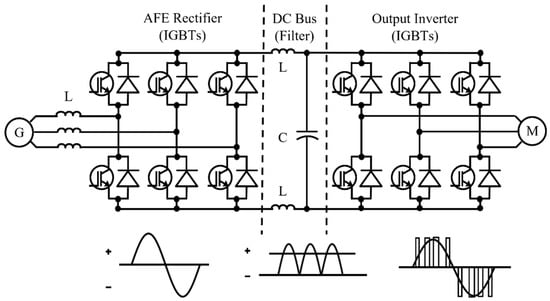
Figure 1.
Configuration of power conversion equipment for small- and medium-sized electric propulsion ships.
2.1. Continuous PWM Method
2.1.1. Sinusoidal PWM
Sinusoidal PWM (SPWM) modulates the pulse width using a sine waveform as the reference voltage to generate gating pulses. This method determines the switching point by comparing the reference voltage to that of a triangular carrier wave. The inverter output voltage is controlled by comparing the sinusoidal command voltage with the triangular carrier wave, generating gating pulses, and averaging them to modulate the voltage. The peak-to-peak value of the triangular carrier wave is selected as the DC input voltage; the reference voltage (Vref) is required to be smaller than the maximum value of the triangular carrier wave (Vc). The gating pulse is generated by comparing the reference voltage and triangular carrier wave, as shown in Inequality (1).
In Inequality (1), the state of the upper switch is shown; the lower switch generates a gating pulse complementary to the upper switch as a set.
Figure 2 illustrates the operating principle of the SPWM method. As shown in Inequality (1), the gate pulse is generated by comparing the reference voltage and the triangular carrier wave. The line voltage represents Vdc/2 when the upper switch is ON and −Vdc/2 when the upper switch is OFF. The average pulse-shaped output line voltage appears as a sine wave equal to the reference voltage. This method is widely used owing to its simplicity and ease of implementation. The switching frequency of the inverter is the same as that of the triangular carrier wave, and modulation occurs at every sampling; thus, the harmonic performance is excellent. However, when the modulation index exceeds 1, linearity of control is lost; therefore, the maximum fundamental voltage that can be linearly obtained is Vdc/2, resulting in low utilization of the DC input voltage.
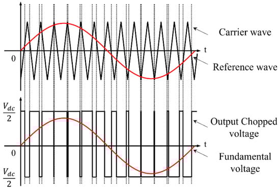
Figure 2.
Operating principle of the SPWM method.
2.1.2. Space Vector PWM
Space-vector pulse-width modulation (SVPWM) is mainly used for converting AC power to control various speeds and torques. This technology is primarily implemented with an inverter and is used in various applications, such as motor control. SVPWM has several advantages over SPWM. The basic concept is to control the output voltage by representing the voltage generated from phases A and B as space vectors.
Figure 3 shows the voltage vector diagram of the 2-level inverter. The working principle of the SVPWM is as follows: Initially, SVPWM generates the reference voltage vector (Vref) from the two-phase channels (phases A and B). This reference voltage vector may be located at different positions over time and constitutes circles in space. The reference voltage vector is then synthesized with the space vectors (V0–V7) produced, depending on the switching state of the inverter. SVPWM controls three voltage vectors close to the reference voltage to generate an accurate output voltage. This control is realized by adjusting the cycle and timing of PWM. The timing of each state ensures that the given output voltage vectors produce the desired voltage.
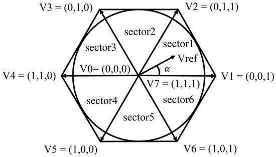
Figure 3.
Voltage vector diagram of a 2-level inverter.
SVPWM enables more precise control, higher voltage usage efficiency, and smaller voltage harmonics, thereby offering lower losses and higher efficiency than SPWM. Owing to these characteristics, SVPWM has become the preferred PWM control technology in various applications that demand high performance and accuracy.
2.2. Discontinuous PWM (DPWM) Method
The discontinuous PWM method places discontinuous sections in which only two out of the three phases switch during the modulation cycle. This reduces the number of switches and minimizes the switching loss. The characteristics of the switching loss and harmonics may vary depending on the location of the non-switching discontinuous sections. Although the discontinuous modulation sections can be freely set, they are typically positioned near the peak of the phase current because the switching loss is proportional to the magnitude of the switch current.
2.2.1. The 60° DPWM Method
The 60° DPWM method avoids switching during the 60° section of the voltage cycle, where the reference voltage has the largest magnitude. The pole voltage command is fixed at Vdc/2 during the 60° section with the highest phase voltage command and at −Vdc/2 during the negative 60° section. This can be implemented by adding an offset voltage to the reference voltage, which for the 60° DPWM method is as follows:
The maximum reference voltage among the three-phase reference voltages is represented by , and the minimum reference voltage is represented by . If the sum of the maximum reference voltage () and minimum reference voltage () is greater than or equal to zero, an offset voltage that can fix to is added to all reference voltage commands. If it is less than zero, an offset voltage that can fix to − is added. This method is applied to loads with an almost unity power factor, in-phase voltage, and current. This offers the advantage of minimizing switching losses in applications such as uninterrupted power supply (UPS), permanent magnet synchronous motor (PMSM) drives, and grid-connected inverters. Figure 4 shows the discontinuous sections of the three-phase reference voltage and voltage vector diagram based on Phase A.
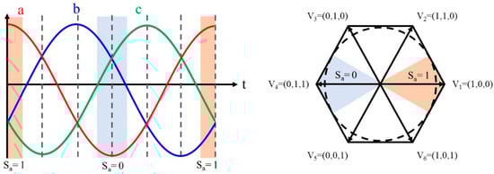
Figure 4.
Operation of 60° DPWM.
2.2.2. The 30° DPWM method
Unlike the 60° DPWM method, the 30° DPWM method arranges four 30° discontinuous modulation sections in one cycle. Figure 5 illustrates the discontinuous sections in the reference voltage and voltage vector diagram for one cycle; unlike the 60° DPWM, the reference voltage peak is divided into two sections with discontinuous areas. The offset voltage for the 30° DPWM method is as follows:
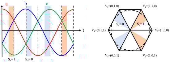
Figure 5.
Operation of 30° DPWM.
Unlike the 60° DPWM method, the 30° DPWM method adds an offset voltage to all reference voltages such that if the sum of the maximum reference voltage () and the minimum reference voltage () is greater than or equal to zero, can be fixed at −, and can be fixed at . If the value is less than zero, an offset voltage is added to fix at . The 30° DPWM method has the advantage of minimizing harmonic losses because it has a smaller current ripple than the 60° DPWM method.
The conventional PWM methods can vary in terms of total harmonic distortion (THD) and switching loss, depending on the operating conditions. Additionally, depending on the application, a suitable criterion must be used to select the PWM method. Continuous PWM (SPWM and SVPWM) can achieve a low THD owing to its high switching frequency; however, it results in a high switching loss, leading to reduced efficiency. Conversely, discontinuous PWM (DPWM) can achieve a high THD owing to a low switching frequency; however, it results in a low switching loss and increased efficiency. Hence, this study analyzes the operating conditions of electric propulsion ships and proposes an optimal PWM method application.
3. Proposed Hybrid Pulse Width Modulation (HPWM) Method
One of the main challenges to fuel conservation in an electric propulsion ship environment is the marine conditions for navigation. Particularly, optimizing inverter performance is an essential technical element in such marine environments. Enhancing inverter efficiency contributes to reducing fuel consumption. Furthermore, the relatively low total harmonic distortion (THD) essential for a normal motor’s operation may become less significant in harsh marine environments. In such scenarios, emphasis should be on the motor’s operational stability and reliability. Hence, the output performance has to be optimized by selecting an appropriate PWM control method to ensure that the inverter operates stably and accurately controls the motor even under harsh marine conditions. For example, in situations requiring a low output voltage and high frequency, the output performance of the inverter can vary significantly depending on the PWM method. Therefore, it is crucial to determine an appropriate pulse-width modulation (PWM) control method that considers these conditions.
The operational conditions for analyzing the inverter performance according to each PWM method are the changes in the frequency and magnitude of the output voltage. The conditions for the experiment are detailed in Figure 10 and Table 1 below. In the frequency-variation condition, as depicted in Figure 6a, the THD of the output current or inverter efficiency does not significantly differ despite changes in frequency. On output voltage magnitude variation, shown in Figure 6b, the harmonic distortion of the output current significantly varies depending on the output voltage magnitude. Under conditions of low output voltage, a significant difference in the harmonic performance can be observed. Although the DPWM method reduces losses, there may be limitations in its application owing to significant differences in harmonic performance under low-output-voltage conditions. Therefore, this study proposes a hybrid pulse-width modulation (PWM) method to achieve optimal performance in accordance with output voltage variations. This method enables us to obtain the optimal PWM method that improves harmonic distortion while reducing losses according to the operational conditions.

Table 1.
Parameters for experiment and system constants.
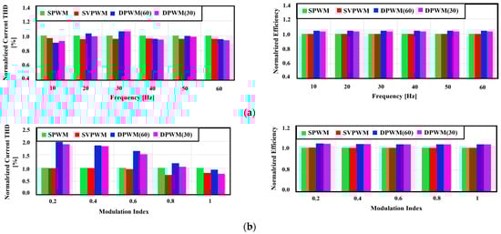
Figure 6.
THD of output current and inverter efficiency according to the operation conditions of the inverter for each PWM method: (a) change in output frequency, (b) change in output voltage magnitude.
The proposed HPWM method (Figure 7) measures the 3-phase current to create a reference voltage and uses it to calculate the modulation index. The offset voltage for the proposed HPWM method is calculated using this modulation index. The offset voltage is computed to enable discontinuous switching at the maximum current using a 3-phase current. Consequently, the HPWM method can achieve lower switching losses under discontinuous PWM operating conditions.
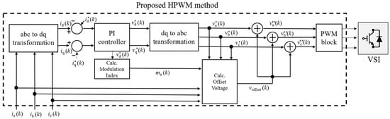
Figure 7.
Block diagram of the proposed HPWM method. is load current, is d-q axis current, is d-q axis current reference, is d-q axis voltage, is d-q axis voltage reference, is modulation index, is 3-phase voltage reference, is offset voltage, and is 3-phase voltage reference modified by offset voltage.
Figure 8 presents a flowchart for calculating the offset voltage in the proposed HPWM method when the modulation index is high (ma > 0.8). The proposed method calculated the offset voltage based on the positions of the reference voltage and current. It sets the discontinuous section where the current is at its maximum to minimize the switching losses. Unlike other DPWM methods, this enables changing the discontinuous section depending on the load operating conditions (power factor variation), thereby reducing the switching losses independent of the load.
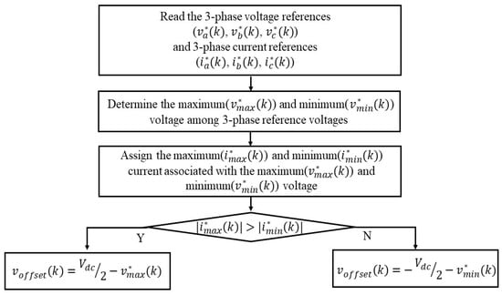
Figure 8.
Flowchart for calculating offset voltage for the proposed HPWM method.
Figure 9 shows the overall flowchart of the proposed HPWM method. This method was designed to optimize output performance and switching losses using a hybrid approach. In this study, the reference value for dividing the modulation index area is 0.8. The reason is that when the modulation index of 0.8 is taken as the reference, the performance difference of THD of each PWM is found, and significant results can be obtained. Therefore, in this study, a low modulation index is defined as a modulation index < 0.8, and a high modulation index is defined as a modulation index > 0.8 in the HPWM. In the low modulation index section (ma < 0.8), the proposed HPWM method applies SVPWM, thus achieving an improved output current THD compared with conventional DPWM methods. Additionally, in the high-modulation-index section (ma > 0.8), low losses could not be obtained by applying the DPWM method, and no significant difference in the output current THD was observed. Furthermore, HPWM that applies a discontinuous section using the magnitude of the output current exhibits better efficiency than conventional DPWM methods. In conclusion, the proposed HPWM method shows superior performance compared with the existing methods and is experimentally verified in the following section.
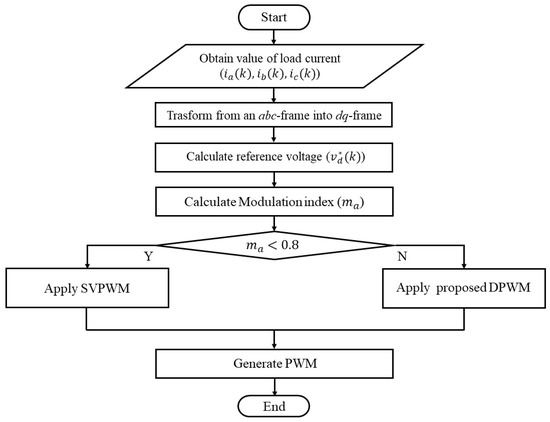
Figure 9.
Flowchart of the proposed HPWM method.
4. Experiment Results
The proposed hybrid PWM (HPWM) method was verified by comparing its performance with those of continuous PWM methods (SPWM and SVPWM) and discontinuous PWM methods (DPWM (60) and DPWM (30)). The PWM methods were compared under identical experimental conditions. The proposed method alters the PWM method depending on the modulation index; hence, experimental conditions were used to compare the output performance of each PWM method according to the changes in the modulation index and were compared at indexes of 0.5 and 0.9.
Figure 10 shows photographs of the experimental apparatus used to verify the proposed HPWM method. Figure 10a depicts the control section, including the DSP and power boards. Figure 10b illustrates the power conversion section, consisting of a three-phase inverter and gate driver. Figure 10c demonstrates the 2.2 kW induction motor and dynamometer used for load application in the experiment. Table 1 lists the experimental parameters.
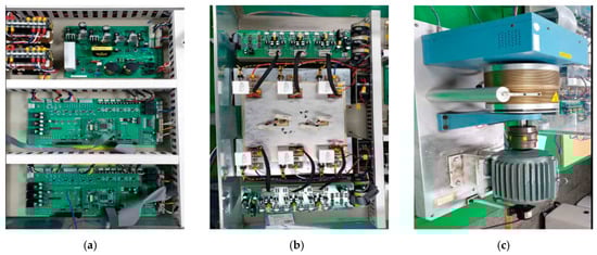
Figure 10.
A 2-level 3-phase inverter and induction motor/load system: (a) microcontroller, (b) 3-phase inverter, (c) induction motor/load system.
Figure 11 shows the experimental results obtained by applying the existing PWM methods individually. The proposed method changes the PWM methods based on the modulation index; therefore, the performances of the existing methods were compared with the modulation index. Moreover, under a modulation index of 0.5, all the methods produce balanced three-phase output currents. However, variations in the output current performance were observed among the different PWM methods. According to the FFT analysis results, at Ma = 0.5, DPWM(30) and DPWM(60) contain more harmonics than SPWM and SVPWM. The SPWM and SVPWM achieved excellent output performances through continuous switching and can be confirmed through FFT analysis. Further, DPWM methods exhibit inferior output current performance compared with CPMW methods owing to their lack of continuous switching despite discontinuous sections, as confirmed by the FFT results. However, owing to discontinuous intervals, DPWM methods can increase the efficiency by reducing losses.
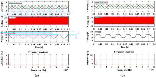
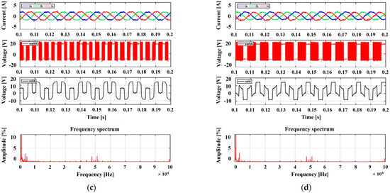
Figure 11.
Experimental results according to traditional PWM methods for the 2-level inverter: 3-phase output current, phase-a switching pattern, phase-a reference voltage, phase-a current FFT results (modulation index = 0.5). (a) SPWM, (b) SVPWM, (c) DPWM(30), (d) DPWM(60).
Figure 12 shows the experimental results obtained by applying each of the existing PWM methods under a high-modulation-index condition (Ma = 0.9). Similar to the modulation index 0.5, all methods produce balanced three-phase output currents. However, in terms of output current performance, the FFT analysis shows that at Ma = 0.9, the harmonic content of SPWM, SVPWM, DPWM(30), and DPWM(60) is similar, so there is no significant difference between the CPWM and DPWM schemes in terms of output current THD performance. This similarity is also evident in the FFT results, which show that the magnitudes of the harmonics are comparable between the CPMW and DPWM methods. Therefore, under high-modulation-index conditions, DPWM methods can reduce losses without affecting the output current performance, making them more advantageous. Thus, the proposed method utilizes SVPWM for the current output when the modulation index is low (as DPWM does not show significantly better results than CPWM) and employs the proposed DPWM method for high modulation index areas where the output current does not differ significantly, making the HPWM approach advantageous.
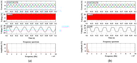
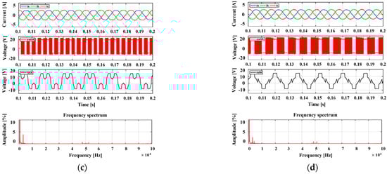
Figure 12.
Experimental results according to traditional PWM methods for the 2-level inverter: 3-phase output current, phase-a switching pattern, phase-a reference voltage, phase-a current FFT results (modulation index = 0.9). (a) SPWM, (b) SVPWM, (c) DPWM(30), (d) DPWM(60).
Figure 13 illustrates the experimental results obtained using the proposed HPWM method, which applies SVPWM under low-modulation-index conditions, and the proposed DPWM under high-modulation-index conditions. Thus, the FFT results of the proposed HPWM show that it has good THD performance regardless of the modulation index because it has less harmonic content when measured over the entire range of the modulation index. Additionally, in sections with a high modulation index, the proposed HPWM switches discontinuously in the highest current output region, thus significantly reducing the switching losses.
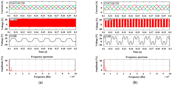
Figure 13.
Experimental results according to the proposed HPWM method for the 2-level inverter: 3-phase output current, phase-a switching pattern, phase-a reference voltage, phase-a current FFT results ((a) modulation index = 0.5, (b) modulation index = 0.9).
Figure 14 shows the HPWM performance under abrupt changes in the modulation index. Even with rapid changes in the modulation index, the proposed HPWM method can adequately calculate the offset voltage and function. It is used when the modulation index is low, thus performing continuous switching until it transitions to discontinuous switching when the modulation index changes.
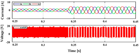
Figure 14.
Experimental results in step-change conditions according to the proposed HPWM method of the 2-level inverter: 3-phase output current, phase-a switching pattern.
Figure 15 illustrates the 3-phase output currents, switching patterns, reference voltage, and offset voltage as a function of the load angle (ϕ) variation according to the proposed method. Our proposed approach calculates the offset voltage for setting the discontinuous region based on the output current. As a result, it ensures that the discontinuous region is always set at the segment where the current reaches its maximum, regardless of how the load angle changes. Figure 15 shows how the offset voltage varies with load angle changes of 15°, 45°, and 75°, leading to corresponding changes in the discontinuous region based on the current. In conclusion, our proposed method effectively reduces switching losses by consistently aligning the discontinuous region with the maximum current, outperforming other algorithms.
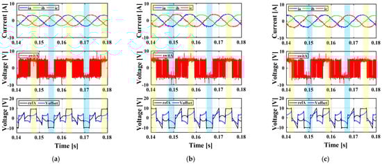
Figure 15.
Experimental results for the proposed HPWM method in a 2-level inverter under varying load angles (ϕ): (a) ϕ = 15°, (b) ϕ = 45°, (c) ϕ = 75° (3-phase output currents, phase-a switching states, reference voltage, and offset voltage).
Figure 16 shows the experimental results of the proposed HPWM under the load profile conditions of an electric propulsion ship. The proposed method accurately tracks the reference speed under conditions of speed load changes for electric propulsion ships. As a result, it can be confirmed that the three-phase output current and reference voltage are accurately controlled. This confirms that the proposed method is capable of reducing losses and can also be applied to the speed load of electric propulsion ships. In Table 2, the load profile shown in the graph above has been expanded to a 10 min load profile in order to apply the proposed method to electric propulsion ships, and the output performance according to each PWM method is summarized in Table 2. The proposed method improves output performance and has the highest efficiency. Additionally, the results of the analysis divided into low-speed and high-speed conditions are shown in Table 3. Although performance changes depending on low-speed and high-speed conditions, the performance difference depending on the algorithm is almost the same. In other words, the proposed method shows excellent performance under low or high speed conditions. Table 4 shows the results of comparing the performance of each PWM under 100 kW class ship conditions to confirm applicability to actual propulsion ships. The proposed method also allows resumption in 100 kW marine dots. As a result, the proposed method can provide practical applications in ships as well.
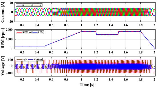
Figure 16.
Experimental results of the proposed HPWM method according to changes in the load profile of electric propulsion ships (3-phase output currents, rpm and rpm reference of motor, reference voltage, and offset voltage).
Table 2.
Summary of performance comparison according to modulation index under ship’s 10 min load profile conditions.
Table 3.
Summary of performance comparison according to changes in low- and high-speed conditions of the ship.
Table 4.
Summary of performance comparison of each PWM method according to 100 kW ship-rated load conditions.
Figure 17 shows the output current THD, total loss, and efficiency of the inverter for each PWM method. As shown in Figure 16a, the CPWM methods (SPWM and SVPWM) exhibited superior output current THD compared with the DPWM methods. The proposed method applies hybrid PWM according to the modulation index, thereby achieving excellent performance in all modulation index ranges. The THD output current is calculated as follows [20]:
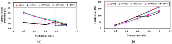
Figure 17.
Comparison of (a) output current THD and (b) loss performance according to each PWM method.
, represent the fundamental frequency and nth harmonic components of the output current, respectively. n was calculated based on 8335 samples in the experiment. As shown in Figure 17b, the DPWM methods outperformed the CPWM methods in terms of loss performance. This is because the switching loss is reduced in the discontinuous regions. The proposed hybrid PWM method adjusts the technique according to the modulation index, thereby achieving the lowest loss when the modulation index is high. This is because the discontinuous region is created by deriving the highest-current region, thereby reducing the switching loss. This loss can be calculated by representing the fundamental frequency and the nth harmonic component of the output current. n was calculated based on 8335 samples in the experiment. The DPWM methods outperformed the CPWM methods in terms of loss performance (Figure 17b). This is because the switching loss is reduced in the discontinuous regions. The proposed hybrid PWM method adjusts the PWM technique according to the modulation index, thereby achieving the lowest loss when the modulation index is high. This is because the discontinuous region is created by deriving the highest-current region, thereby reducing the switching loss the most. The loss is calculated as follows [8]:
, , represent the inverter loss, input power, and output power, respectively. The inverter loss can be calculated by measuring the input and output power of the inverter.
Figure 18 illustrates the output current THD, inverter total loss, and efficiency for various PWM methods under different load angle variation conditions. The proposed algorithm was tested with a modulation index set at 0.8 to minimize losses. With varying load angles, as shown in Figure 18a, the current THD exhibited negligible changes. However, for the DPWM methods, variations in the loss occurred owing to changes in the maximum current point with load angle fluctuations. Our proposed method, designed to track the maximum current value consistently, ensured low losses even with changing load angles. This establishes a significant advantage of our proposed approach, which maintains high efficiency despite load angle variations.
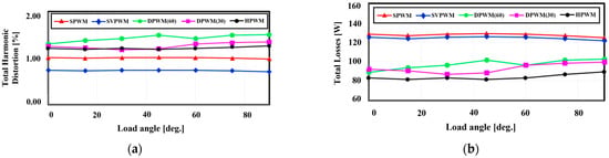
Figure 18.
Comparison of (a) output current THD and (b) loss performance according to each PWM method during load angle changes (modulation index = 0.8).
Figure 19 shows the output current THD, total inverter losses, and efficiencies for different carrier frequency variations associated with each PWM method; a modulation index of 0.8 was utilized. As the carrier frequency increased (Figure 19a), the current THD decreased. In addition, as shown in Figure 19b, the losses increase. The proposed method demonstrated the ability to maintain the lowest switching losses across all frequency ranges.
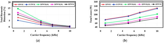
Figure 19.
Comparison of (a) output current THD and (b) loss performance according to each PWM method during switching frequency changes (modulation index = 0.8).
Table 5 summarizes a comparison of the output performances of each PWM method. The output performance of each PWM was compared relative to various analysis conditions. Originally, the smaller the value of total loss, the better the performance. Although HPWM is high when the modulation index is as low as 0.5, we determined that the total loss performance is better because the losses in the low modulation index range is smaller than the losses in the high modulation index range compared to the conventional PWM methods. The same is true for the THD performance analysis. The proposed method applies a hybrid method for optimal operation under varying conditions, particularly for maintaining a low-current THD and switching losses in frequency ranges with higher modulation indices.
Table 5.
Summary of performance comparison according to modulation index.
5. Conclusions
As the need for greenhouse gas reduction and carbon neutrality increases, interest in eco-friendly ships is rapidly increasing. Among these, electric propulsion ships are considered a notable alternative, and improvements in electric propulsion systems are needed. However, improving the performance of core ship components such as inverters is an important research task. In this paper, we propose hybrid pulse-width modulation (HPWM) as a new solution to improve inverter performance. In various applications, existing PWM methods were analyzed according to each load profile, so this paper also performed an initial analysis of existing PWM methods under the load profile conditions of electric propulsion ships and confirmed that the output current THD and inverter loss change according to the modulation index. The PWM performance evaluation prioritizes the output current THD value and considers the switching loss if the values are similar. CPWM has good THD at a low modulation index but poor switching loss at a high modulation index, while DPWM has poor THD performance at a low modulation index but similar THD performance to CPWM at a high modulation index and lower switching loss. Based on this, we designed a proposed HPWM that performs optimally in each modulation index band. This method applies space-vector pulse-width modulation (SVPWM) in the low modulation index region and the proposed DPWM in the high modulation index region. In particular, in the high modulation index region, the offset voltage calculation method is designed to track the highest current value to set the discontinuous modulation range, unlike the conventional DPWM, which sets the discontinuous modulation range in the range near the peak value of the phase current. The proposed method was compared with existing PWM methods under operating conditions (voltage change, frequency change) that may occur in electric propulsion ships. In particular, the performance of the proposed method was confirmed even under representative ship load profile conditions. The performance of the proposed HPWM method was experimentally verified through a dynamometer experiment using a 2.2 kW induction motor. As a result, the proposed HPWM scheme shows better overall THD and total losses performance than the conventional PWM scheme by minimizing the THD of the output current in the low modulation index region and minimizing the total loss in the high modulation index region under various operating conditions. In future research, we plan to apply the proposed method to an inverter for fishing boats of approximately 100 kW. Therefore, this study demonstrated the effectiveness and advantages of the HPWM method, which realizes optimal performance by adjusting the operating characteristics of the inverter according to the modulation index range.
Author Contributions
J.-s.K. managed the project; C.R., H.-m.J. and S.-w.K. performed the numerical simulation and analysis; C.R. and S.-w.S. drafted the paper; S.-w.S. and N.-y.L. edited the figure; J.-s.K. edited the paper. All authors contributed to this study. All authors have read and agreed to the published version of the manuscript.
Funding
This research was supported by Korea institute of Marine Science & Technology Promotion(KIMST) funded by the Ministry of Oceans and Fisheries (No. 20210369 & No. 20220603).
Data Availability Statement
This content cannot be shared.
Conflicts of Interest
The authors declare no conflicts of interest.
References
- United Nations Framework Convention on Climate Change. Available online: https://unfccc.int/resource/docs/convkp/conveng.pdf (accessed on 15 January 2022).
- IMO. Fourth Greenhouse Gas Study 2020; IMO: London, UK, 2021. [Google Scholar]
- IMO. The 76th Session of the Marine Environment Protection Committee, MEPC 76; IMO: London, UK, 2021. [Google Scholar]
- Lim, C.O.; Park, B.C.; Lee, J.C.; Kim, E.S.; Shin, S.C. Electric power consumption predictive modeling of an electric propulsion ship considering the marine environment. Int. J. Nav. Archit. Ocean. Eng. 2019, 11, 765–781. [Google Scholar] [CrossRef]
- Park, C.; Jeong, B.; Zhou, P.; Jang, H.; Kim, S.; Jeon, H.; Nam, D.; Rashedi, A. Live-life cycle assessment of the electric propulsion ship using solar PV. Appl. Energy 2022, 309, 118477. [Google Scholar] [CrossRef]
- Ericsen, T.; Hingorani, N.; Khersonsky, Y. Power electronics and future marine electrical systems. IEEE Trans. Ind. Appl. 2006, 42, 155–163. [Google Scholar] [CrossRef]
- Roh, C. Optimal selection among various three-phase four-wire back-to-back (BTB) converters with comparative analysis for wave energy converters. Processes 2023, 11, 1463. [Google Scholar] [CrossRef]
- Roh, C. Performance comparisons of three-phase/four-wire model predictive control-based DC/AC inverters capable of asymmetric operation for wave energy converters. Energies 2022, 15, 2839. [Google Scholar] [CrossRef]
- Schonung, A. Static Frequency Changers with ‘Subharmonic’ Control in Conjunction with Reversible Variable-Speed A.C.Drives. Brown Boveri Rev. 1964, 51, 555–577. [Google Scholar]
- Pou, J.; Zaragoza, J.; Ceballos, S.; Saeedifard, M.; Boroyevich, D. A carrier-based PWM strategy with zero-sequence voltage injection for a three-level neutral-point-clamped converter. IEEE Trans. Power Electron. 2012, 27, 642–651. [Google Scholar] [CrossRef]
- van der Broeck, H.W.; Skudelny, H.-C.; Stanke, G.V. Analysis and realization of a pulsewidth modulator based on voltage space vectors. IEEE Trans. Ind. Appl. 1988, 24, 142–150. [Google Scholar] [CrossRef]
- Kim, T.J.; Kang, D.W.; Lee, Y.H.; Hyun, D.S. The analysis of conduction and switching losses in multi-level inverter system. In Proceedings of the IEEE 32nd Annual Power Electronics Specialists Conference, Vancouver, BC, Canada, 17–21 June 2001; pp. 1363–1368. [Google Scholar]
- Ayano, H.; Nakagaki, T.; Iguchi, Y.; Matsui, Y.; Itoh, J.-i. Theoretical study of rampwise DPWM technique to reduce motor acoustic noise. IEEE Trans. Power Electron. 2023, 38, 8102–8114. [Google Scholar] [CrossRef]
- Ruiz-González, A.; Heredia-Larrubia, J.-R.; Pérez-Hidalgo, F.M.; Meco-Gutiérrez, M.J. Discontinuous PWM strategy with frequency modulation for vibration reduction in asynchronous machines. Machines 2023, 11, 705. [Google Scholar] [CrossRef]
- Zeng, J.; Li, Z.; Yang, L.; Huang, Z.; Huang, J.; Huang, Y.; Yang, B.; Yu, T. Dynamic space vector based discontinuous PWM for three-level inverters. Int. J. Electr. Power Energy Syst. 2020, 117, 105638. [Google Scholar] [CrossRef]
- Ko, Y.; Kuprat, J.; Pugliese, S.; Liserre, M. Modulation strategies for thermal stress control of CHB inverters. IEEE Trans. Power Electron. 2022, 37, 3515–3527. [Google Scholar] [CrossRef]
- Xu, J.; Soeiro, T.B.; Gao, F.; Tang, H.; Bauer, P. Carrier-based generalized discontinuous PWM strategy for single-phase three-legs active power decoupling converters. IEEE Trans. Ind. Electron. 2021, 68, 11609–11613. [Google Scholar] [CrossRef]
- John, A. Beverley, Chapter VIII Electric Propulsion Drives. In Marine Engineering; Roy, L.H., Ed.; Society of Naval Architects and Marine Engineers: Jersey, NJ, USA, 1992. [Google Scholar]
- Renz, E.C.; Turso, J. Toward the Application of Pulse Width Modulated (PWM) Inverter Drive-Based Electric Propulsion to Ice Capable Ships. Energies 2022, 15, 8217. [Google Scholar] [CrossRef]
- Kwak, S.; Park, J.C. Predictive control method with future zero-sequence voltage to reduce switching losses in three-phase voltage source inverters. IEEE Trans. Power Electron. 2014, 30, 1558–1566. [Google Scholar] [CrossRef]
Disclaimer/Publisher’s Note: The statements, opinions and data contained in all publications are solely those of the individual author(s) and contributor(s) and not of MDPI and/or the editor(s). MDPI and/or the editor(s) disclaim responsibility for any injury to people or property resulting from any ideas, methods, instructions or products referred to in the content. |
© 2024 by the authors. Licensee MDPI, Basel, Switzerland. This article is an open access article distributed under the terms and conditions of the Creative Commons Attribution (CC BY) license (https://creativecommons.org/licenses/by/4.0/).