Abstract
The chain drive system, being one of the core subsystems of the scraper conveyor, greatly influences the coal-conveying efficiency due to its dynamic characteristics. Therefore, this paper employed an experimental method to compare the dynamic characteristics of the chain rings at various positions within the chain drive system. This article simulated the three most common working conditions. The results indicated that the chain speed, load, and surface undulation had a stimulating effect on chain vibration, with the most significant impact observed on the chain ring located in the middle of the adjacent scraper. The scraper exerted an inhibitory effect on the vibration of the chain ring. Among the factors studied, the load had the most significant influence on the transverse direction. When there was surface undulation, the vibration of the chain ring in the running direction formed an ‘N’ shape. This condition intensified the vibration during uphill and downhill stages while suppressing vibration at the slope peak. This research holds great significance in enhancing operation stability.
1. Introduction
Fully mechanized mining technology represents the most advanced coal mining approach to date, comprising three main mechanical devices: shearer, scraper conveyor, and hydraulic support [1,2]. In 1940, the Germans invented the first scraper conveyor, which has more than 80 years of history. It is the ‘artery’ of the fully mechanized mining face and is responsible for transporting coal and bearing the running track of the shearer. According to statistics, in accidents involving the three-machine system on a fully mechanized mining face, the accident caused by a scraper conveyor accounts for up to 40%. The total time of chain drive system (ring chain, sprocket) failure in the scraper conveyor reaches a significant 78.1% [3,4].
Consequently, the chain drive system stands out as the most vulnerable component of the scraper conveyor. Studying its dynamic characteristics is imperative, as it holds immense significance in enhancing the efficiency and operation stability of coal conveying.
During the study of the chain drive system’s dynamic characteristics, many scholars took into account the confined working environment of the scraper conveyor in the mine. Conducting field tests is costly, time-consuming, and labor-intensive. Therefore, most researchers opted to study the dynamic characteristics of the chain drive system through test bench setups or simulations [5]. To closely simulate the actual coal-conveying conditions of the chain drive system, scholars often employed the joint simulation method. For instance, they utilized a combination of ADAMS, EDEM, ANSYS, and MATLAB/Simulink software to recreate real working conditions accurately. Indeed, the joint simulation method is a valuable research approach. Subsequently, the focus lies on studying the dynamic characteristics of the chain drive system [6,7,8]. Świder et al. [9] established a chain drive system simulation model based on Adams-Simulink. The simulation revealed that the change of load resulted in changes in torque, and the torque was directly proportional to the current of the motor. Wang et al. [10] employed MBD-DEM-FEM joint simulation to investigate the movement of scraper and material, as well as the force of the chain link in the chain drive system under chain-clamping conditions. Zhang et al. [11] utilized Ansys and SolidWorks to establish a three-dimensional model of the scraper. Through optimization, they found that a well-shaped stiffener design significantly enhanced the mechanical properties of the scraper and extended the service life.
Furthermore, in order to further improve the accuracy of the simulation model, scholars conducted optimizations to study the dynamic characteristics of the chain drive system [12]. Yuan et al. [13] divided the chain into multiple discrete segments using the finite segment method and interconnected them through the Kelvin–Voigt model. The model can achieve the irregular polygon effect during the meshing of the sprocket and the chain ring, enabling the analysis of the dynamic characteristics of the middle groove bending. Shprekher et al. [14,15] used a multi-mass system to establish a general calculation model of the chain drive system, considering the motor, reducer, and drive sprocket. They conducted simulations of the full-load and no-load starting processes under the multi-machine drive. The findings indicated that the proposed multi-mass model achieved a simulation speed twice as fast as the single-mass model, with a chain running speed error of only 5%. Zhang et al. [16] established a multibody dynamic model of the chain drive system and validated its performance of the model through fixed-point strain measurement experiments. They also introduced a new tension distribution estimation method to monitor the dynamic characteristics of scraper chain tension. Scholars also used experimental methods to study the dynamic characteristics of chain drive systems [17]. Jiang et al. [18,19,20] constructed a test bench to monitor the speed difference between the head and tail sprockets of the chain drive system under various chain speeds, terrain, and loads. Through spectrum analysis, they investigated the main factors influencing the dynamic characteristics of the chain drive system, and they found that the tighter the chain, the smaller the speed difference between the two sprockets, and the secondary meshing frequency of the reducer had a significant impact on the running stability of the chain drive system. Furthermore, in reference [19], only the dynamic characteristics of a single chain link under abnormal working conditions were examined. However, in practical applications, the scraper conveyor chain transmission system in use in mines contains hundreds or thousands of chain links. The dynamic characteristics displayed by different positions of chain links vary, highlighting the need to analyze and study the chain links at different positions. Wojnar et al. [21] studied the dynamic characteristics of the reducer. Through their research, they identified five positions on the reducer shell that could effectively describe the vibration of the reducer gear. These positions serve as important indicators to monitor the dynamic characteristics of the chain drive system.
The scraper conveyor is a nonlinear, strongly coupled system with intricate interrelationships between its components [22,23]. The transmission power from the drive system to the chain drive system plays a crucial role in determining its dynamic characteristics. Scholars also explored methods to enhance the dynamic characteristics of the chain drive system during operation, such as implementing permanent magnet direct drive or soft start techniques [24,25]. Indeed, before enhancing the dynamics of the chain drive system, it is essential to have a comprehensive understanding of its operating state. The evaluation of dynamic characteristics of the chain drive system primarily revolves around factors like the tension between the chain rings, the torsional vibration of the chain ring or scraper, and the vibration of the middle groove [26,27,28]. Liu et al. [29] analyzed the torsional vibration of the chain drive system and the force exerted on the scraper. Wang et al. [30] studied the crack initiation characteristics of the scraper chain using time-varying dynamic analysis and acquired data on the tension changes in the scraper chain. Zhang et al. [31] analyzed the vibration characteristics in the middle groove of the chain drive system as a means of diagnosing the faults in the scraper chain.
When studying the dynamic characteristics of the chain drive system, a significant number of parameters require calibration through simulations, making it challenging to accurately represent real working conditions. Hence, this paper addresses the study of dynamic characteristics by building a test bench. Moreover, it was observed that most of the above scholars primarily focused on analyzing the dynamic characteristics of the entire chain drive system or a single chain ring. However, there are few comparative studies concerning the dynamic characteristics of chain rings at different positions.
With this in mind, this paper first builds a test bench for the chain drive system. It proceeds to simulate the three most common working conditions: variable chain speed, variable load, and surface undulation condition, and then the acceleration signal of the chain ring is gathered. These data are used to compare the vibration of the chain ring at different positions between the two adjacent scrapers. Subsequently, the dynamic characteristics of the chain drive system are evaluated.
2. Research Methods
2.1. Build Test Bench
Figure 1 depicts the multi-system coupling test bench of the scraper conveyor, which comprises a chain drive system, a chain speed adjustment system, and a data acquisition and analysis system. The test bench used frequency converters to obtain different chain speeds for the scraper conveyor, and the parameters used for the scraper conveyor used are presented in Table 1. The data acquisition system captured the acceleration sensor signal at a sampling frequency of 200 Hz, and the sensor parameters are shown in Table 2.
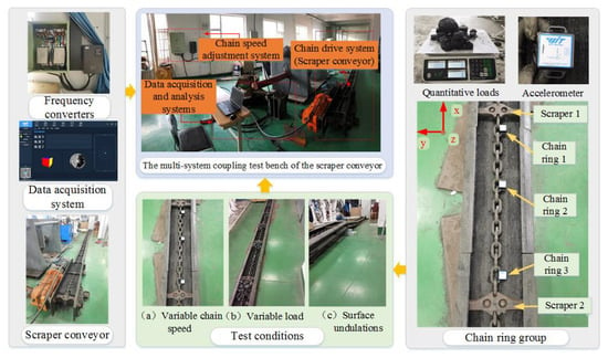
Figure 1.
Test bench construction.

Table 1.
Parameters of the scraper conveyor.

Table 2.
Parameters of acceleration sensor.
The chain drive system’s chain was segmented by the scraper, and each segment can be considered as a chain ring group, as illustrated in the lower right corner of Figure 1. Therefore, understanding the dynamic characteristics of a chain ring group enabled us to infer the dynamic characteristics of the entire chain drive system. Based on the above ideas, the acceleration sensor was attached to chain ring 1, chain ring 2, and chain ring 3 of the chain ring group. The scraper located at the front side of the chain ring group was defined as scraper 1, and the rear side scraper was defined as scraper 2.
Simultaneously, it was stipulated that the coal-conveying direction of the chain drive system was the x direction (running direction), the gravity direction was the z direction (longitudinal direction), and the direction perpendicular to the x direction and z direction was the y direction (transverse direction).
2.2. Test Scheme
The technical roadmap of this paper is shown in Figure 2.
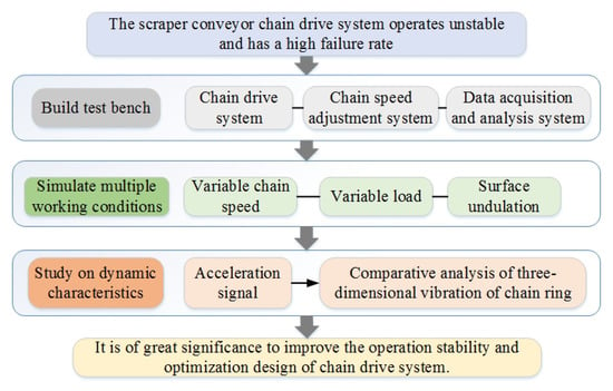
Figure 2.
Technology roadmap.
In this paper, three working conditions were simulated: variable chain speed condition, variable load condition, and surface undulation condition. During the simulation of variable chain speed conditions, different chain speeds can be achieved by adjusting the knob of the frequency converter. The corresponding relationship between chain speed and inverter frequency is shown in Table 3.

Table 3.
The corresponding table of frequency and chain speed.
When simulating the variable load case, four different conditions were simulated: 0 kg (no load condition), 1 kg, 2 kg, and 3 kg were simulated. As shown in the upper right corner of Figure 1, the load’s mass was measured using an electronic scale, and coal blocks were manually loaded and continuously added from the tail end to the middle groove. Finally, when simulating the surface undulation condition, the middle groove was longitudinally undulated by 120 mm. To summarize, all the variables used in the experiment are shown in Table 4.

Table 4.
Variable table of test scheme.
3. Results and Discussion
3.1. Variable Chain Speed Conditions
In the literature [20], the dynamic characteristics of the entire chain drive system under different chain speeds were studied using the vibration signal of the output shaft of the reducer, but the dynamic characteristics of specific local components (such as chain ring, sprocket, and other parts) were not explored in the study. Therefore, this paper conducted a comparative and analytical study of the three-dimensional dynamic characteristics of chain rings at different positions.
3.1.1. Running Direction
Figure 3 illustrates the statistical analysis of the acceleration change trend of the chain ring in the running direction. It can be found that as the chain speed increased, the acceleration fluctuation range of the three rings showed a gradual upward trend. The acceleration intervals corresponding to the maximum and minimum chain velocities (0.0707 m/s, 0.2357 m/s) in this test were statistically calculated and shown in Table 5. It can be observed that the amplitude of the chain ring at 0.2357 m/s was greater than the amplitude at 0.707 m/s. Exactly, the significant tension in the running direction resulted in relatively stable vibration of the chain ring in this direction. Statistics were made for the standard deviation and range of the curve in Figure 3, as shown in Figure 4. Simultaneously, the relationship between the chains was studied by using the acceleration data of chain ring 2 as the denominator and the data of the chain rings 1 and 3 as the numerators.
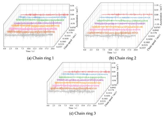
Figure 3.
The acceleration curve of the chain link in the running direction.

Table 5.
Amplitude statistics of chain running direction.
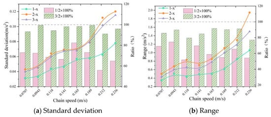
Figure 4.
Vibration data statistics of chain ring in running direction.
As shown in Figure 4, it is evident that with the increase in chain speed, the acceleration standard deviation and range of the chain ring demonstrated a gradual increase trend. This indicates that the chain speed had an excitation effect on the vibration of the chain ring in the running direction. Based on the ratio of the standard deviation and range of the chain ring, the vibration of chain ring 2 was the most violent, followed by chain ring 3 and, finally, chain ring 1. From the structure of the chain drive system, it is evident that chain ring 1, chain ring 2, and chain ring 3 were identical parts, differing only in their spatial position. Chain ring 2 was positioned in the middle of the two scrapers, while chain ring 1 and chain ring 3 were located at the end of the chain ring group, closer to the scraper. It is evident that the scraper had an inhibitory effect on the vibration of the chain link in the running direction. Additionally, a well-designed arrangement of the interval between two adjacent scrapers had a positive stabilizing effect on the dynamic characteristics of coal transportation.
3.1.2. Transverse Direction
Under different chain speeds, the acceleration changes of the chain ring in the transverse direction were counted, as shown in Figure 5.
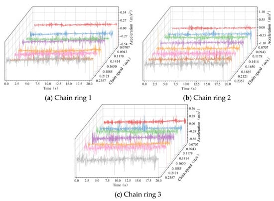
Figure 5.
The acceleration curve of the chain ring in the transverse direction.
The standard deviation, range, and ratio of the acceleration curve of the chain ring in Figure 5 were statistically calculated as shown in Figure 6.
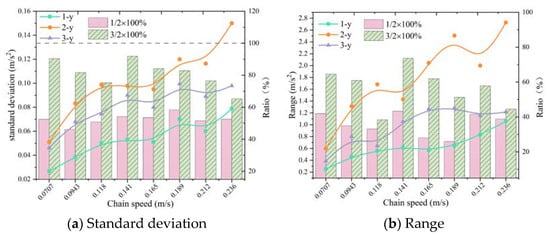
Figure 6.
Vibration data statistics of chain rings in the transverse.
Indeed, from Figure 6, it is evident that as the chain speed increased, the vibration of the three chain rings exhibited an upward trend, indicating that the chain speed had an excitation effect on the lateral vibration of the chain ring.
The standard deviation ratio of chain rings 1 and 2 was [46.06%, 58.33%], the range ratio was [25.94%, 41.97%]. the standard deviation ratio of chain rings 2 and 3 was [65.25%, 91.91%], the range ratio was [38.35%, 73.64%]. From Figure 6 and the ratio ranges, it is evident that the vibration of chain ring 2 was the most significant, followed by chain ring 3 and, finally, chain ring 1. This observation aligns with the findings in the running direction, indicating that the scraper’s dampening effect on the vibration of the chain ring also applied to the transverse direction.
3.1.3. Longitudinal Direction
Figure 7 presents the statistical analysis of the longitudinal acceleration vibration of the chain ring at different chain speeds.
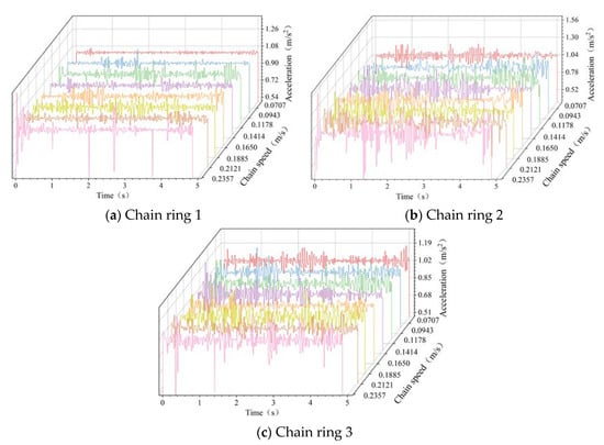
Figure 7.
The acceleration curve of the chain ring in the longitudinal direction.
Figure 8 displays the statistical calculations for the standard deviations, ranges, and ratios of the chain ring acceleration curve depicted in Figure 7.
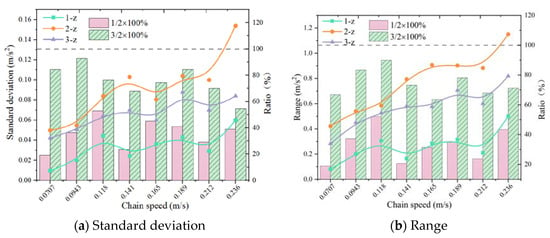
Figure 8.
Vibration data statistics of the chain ring longitudinally.
Figure 8 demonstrates that as the chain speed increased, the vibration of the three chain rings exhibited an upward trend, indicating that the chain speed had an excitation effect on the longitudinal vibration of the chain ring.
The standard deviation ratio range of chain ring 1 and chain ring 2 fell within [19.2%, 52.92%], and the range ratio range was [18.96%, 52.14%]. The standard deviation ratio range of chain ring 2 and chain ring 3 was [54.55%, 92.88%], and the range ratio range was [63.51%, 89.91%]. From Figure 8 and the provided ratio interval, it is evident that the vibration of chain ring 2 was the most obvious, followed by chain ring 3 and, finally, chain ring 1.
3.1.4. Three-Way Comparative Analysis
In this section, a comparison is made regarding the vibration of the chain rings in three directions. The vibration of the chain ring was analyzed using the standard deviation of the acceleration of the chain ring, as illustrated in Figure 9.
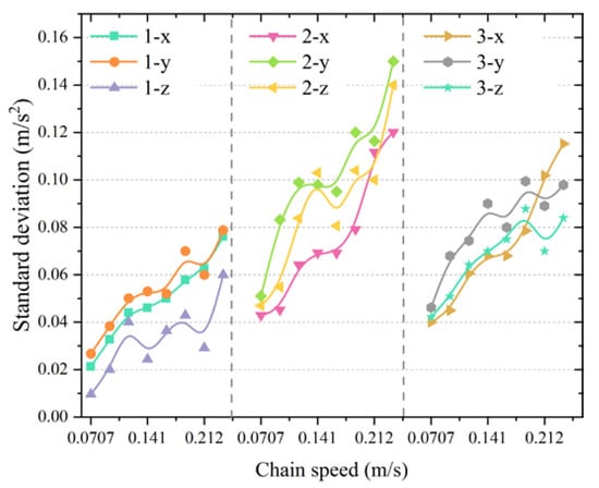
Figure 9.
Comparison of standard deviation of three-direction acceleration of chain ring.
As depicted in the figure, the vibration intensity of chain ring 1 was as follows: y > x > z; chain ring 2 was: y > z > x; chain ring 3 was: y > z > x. The chain rings exhibited the highest vibration in the transverse direction (y-axis). The reason for this was that there were no transverse factors that can effectively suppress vibration. The operation direction was the main direction of coal transportation, and it experienced significant tension. On the other hand, the longitudinal direction was the direction of gravity, and the chain ring was influenced by the upper surface of the middle groove. Both directions had factors that inhibited the vibration of the chain ring.
3.2. Variable Load Conditions
In this section, the dynamic characteristics of the chain ring are studied under variable load conditions, specifically at 0 kg, 1 kg, 2 kg, and 3 kg loads. As the chain ring 3 was pressed by the coal transported on the middle groove, its acceleration could not be directly measured in the test. Consequently, only the three-way acceleration of chain ring 1 and 2 was measured.
As illustrated in Figure 10, Figure 11 and Figure 12, the acceleration curves in the running direction, transverse and longitudinal are shown, respectively. When adjusting the frequency of the inverter to 8 Hz, the chain speed of the chain drive system was set to 0.0943 m/s. Subsequently, the acceleration changes of chain ring 1 and 2 were analyzed.
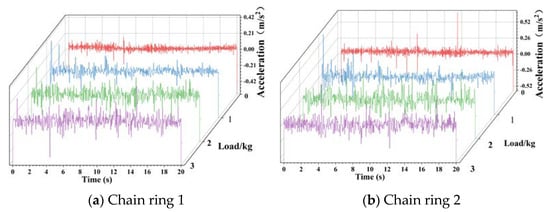
Figure 10.
The acceleration curve of the running direction. (Variable Load Conditions).
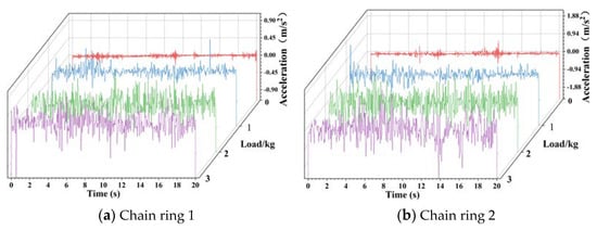
Figure 11.
The acceleration curve of the transverse direction. (Variable Load Conditions).
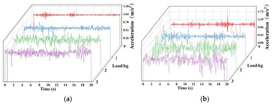
Figure 12.
The acceleration curve of the longitudinal direction. (Variable Load Conditions).
Indeed, as observed in the above figures, the vibration amplitude of both chain ring 1 and chain ring 2 increased with the increase in load in all three directions. To quantitatively study the vibration of chain rings 1 and 2, the standard deviation and range of the curves in the above figure were calculated and are presented in Figure 13a. Simultaneously, the standard deviation and range of the chain ring under different load masses (1 kg, 2 kg, 3 kg) were compared with the standard deviation and range of the no-load (0 kg). The ratio is shown in Table 6 and drawn in Figure 13b.
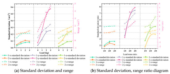
Figure 13.
Statistics of vibration data of chain rings under variable load conditions.

Table 6.
Statistical table of standard deviation and range ratio of chain ring.
As depicted in Figure 13a, it can be observed that within the load range selected in this test, when the chain drive system conveyed coal blocks, the vibration of the chain ring was intensified compared to the no-load condition. This indicates that the load had an incentive effect on the vibration of the chain ring. And this excitation effect will increase within a certain range as the load increases, which aligns with the research results presented in the literature [6]. However, this study only studied the vibration of a chain ring and did not compare and analyze the chain rings at different positions under variable load conditions.
In this paper, the comparative analysis of chain rings at different positions consistently revealed that the vibration of chain ring 2 was greater than that of chain ring 1 under varying load masses. The reason behind the greater vibration of chain ring 2 was that when the excitation effect of the load was transmitted along the chain, the chain ring 2 was closer to the coal pile and experienced a more significant impact. The chain ring 1 was far away from the coal pile and was less affected. Moreover, its proximity to the scraper resulted in the scraper’s inhibitory effect on the fluctuation of the chain ring 1, leading to reduced vibration levels.
In addition, the ratio of Figure 13b shows that the load had the most significant effect on the transverse vibration of the chain ring during the load condition.
3.3. Surface Undulation Conditions
In the mine, the coal mining face was often uneven due to factors such as the movement of hydraulic supports and, so, it was necessary to study this working condition [26]. Figure 14 illustrates the schematic diagram of the surface undulation condition. The chain ring underwent the following sequence: straight condition—uphill condition—slope peak—downhill condition—straight condition in turn. In the surface undulation condition, the terrain formed a convex shape. The height of the middle groove at the uphill and downhill was symmetrical about the highest point of the convexity.
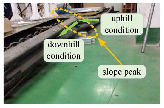
Figure 14.
Schematic diagram of surface undulation conditions.
3.3.1. Running Direction
As depicted in Figure 15, upon entering the surface undulation condition, the acceleration change of the chain ring in the running direction followed an ‘N’-shaped trend, undergoing three distinct stages. Uphill stage: acceleration is gradually increasing; slope peak stage: acceleration reverse mutation, downhill stage: acceleration is gradually increasing.
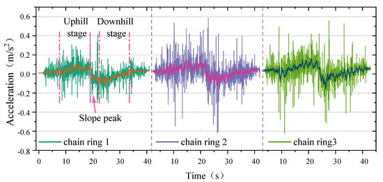
Figure 15.
The acceleration curve of the running direction.(Surface Undulation Conditions).
In the uphill stage, the chain ring acceleration gradually increased in the positive direction. The maximum amplitude of chain ring 2 was 0.545 m/s2; and the maximum amplitude of chain ring 3 was 0.42 m/s2, which was 77.06% of chain ring 2. Meanwhile, the maximum amplitude of chain 1 was 0.305 m/s2, which was 55.96% of chain ring 2. During the first 10 s in the straight condition, a more intense vibration was generated compared to the subsequent movement of the chain ring.
In the slope peak stage, the chain ring reached the highest point of the convex shape, and the acceleration experienced a significant sudden change from positive acceleration to negative acceleration. Additionally, it is evident that the acceleration curve was basically symmetrically distributed in the uphill and downhill stages, and the terrain of the surface undulating conditions was also symmetrical. Therefore, it can be deduced that the trend of the vibration curve of the chain ring in the running direction was influenced by the topography.
In the downhill stage, the chain ring gradually increased from negative acceleration. The maximum amplitude of chain ring 2 was −0.604 m/s2, the maximum amplitude of chain ring 3 was −0.559 m/s2, which was 92.55% of chain ring 2, and the maximum amplitude of chain ring 1 was −0.304 m/s2, which was 50.33% of chain ring 2. Finally, between 33 and 35 s, the chain ring acceleration remained stable near 0, indicating that it entered the straight conveying condition.
The analysis of the three stages revealed that the surface undulation condition excited the vibration of the chain ring in the running direction and had the greatest influence on the chain ring 2, followed by the chain ring 3 and, finally, the chain ring 1.
Moreover, the chain amplitude of the uphill and downhill was calculated and presented in Table 7, as well as plotted in Figure 16. It is evident from the chart that the vibration of the downhill was more intense than that of the uphill. In other words, the chain ring exhibited significant fluctuations when moving downhill. The reason for this was that the tension between the chain ring and the chain ring was smaller during downhill movement compared to uphill, leading to intensified vibration.

Table 7.
Chain ring amplitude statistics table.
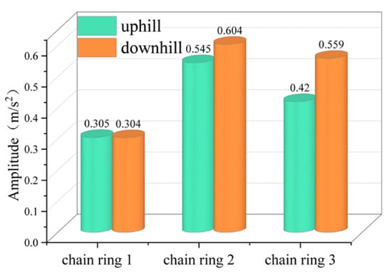
Figure 16.
Chain ring amplitude histogram.
3.3.2. Transverse Direction
Figure 17 displays the acceleration curve of the chain ring in the transverse direction. It is evident from the diagram that the working condition had little effect on chain ring 1. However, it had a great influence on the downhill stage of chain ring 3. The fluctuation range of uphill was 0.908, which was basically the same as that of straight condition, while the amplitude of downhill was 1.427, which was 57.16% higher than that of the straight condition.
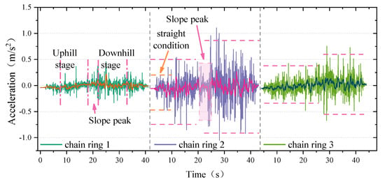
Figure 17.
The acceleration curve of the transverse direction. (Surface Undulation Conditions).
The vibration of the chain ring 2 was the most significant, and the amplitude of the straight condition was 0.667. The vibration during the uphill and downhill stages was intensified, with amplitudes of 1.258 and 1.854, respectively, which were 88.61% and 177.96% higher than the amplitude of the straight condition. In line with the running direction, the vibration during the downhill stage was the most severe. When the chain ring was at the peak of the slope, the vibration of the chain ring will be weakened. During the test, it was observed that there was friction between chain ring 2 and the middle groove, which inhibited the vibration of chain ring 2.
3.3.3. Longitudinal Direction
As shown in Figure 18, the acceleration curve of the chain ring in the longitudinal direction was depicted. The whole process of chain rings 1 and 3 in this working condition remained relatively stable, indicating that the working condition had little effect on its longitudinal vibration.
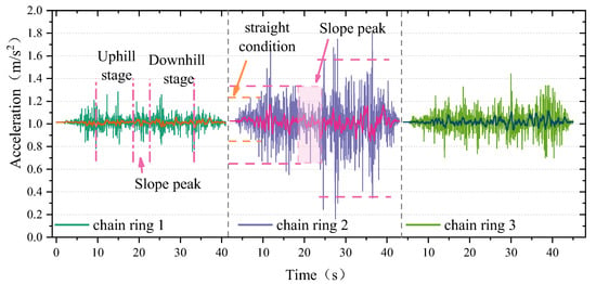
Figure 18.
The acceleration curve of the longitudinal direction. (Surface Undulation Conditions).
The change trend of chain ring 2 in the longitudinal direction was consistent with that in the transverse direction, as it strengthened the vibration during the uphill and downhill stages while it suppressed the vibration at the slope peak. The amplitude of the straight condition was 0.365, the amplitude of the uphill was 0.936, and the amplitude of the downhill was 1.447. The two stages were 156.44% and 296.44% higher than the vibration of the straight condition.
Figure 19 presents the statistical analysis of the vibration growth rate of uphill and downhill in both longitudinal and transverse directions. The figure shows that whether it was uphill or downhill, the longitudinal vibration growth rate was consistently higher than the lateral vibration growth rate. Therefore, this working condition had a greater impact on the longitudinal direction of chain ring 2.
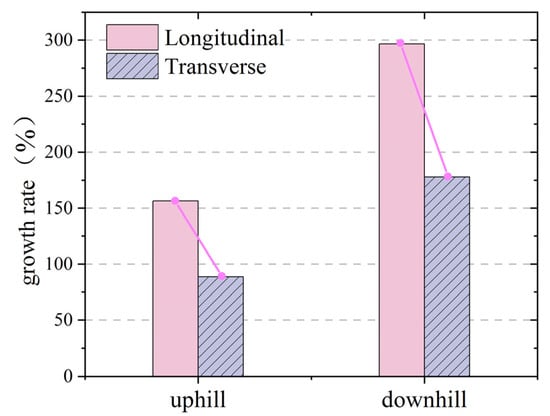
Figure 19.
Vibration growth rate of chain ring 2.
4. Conclusions
In this paper, a chain drive system test bench was first built, and then the dynamic characteristics of the chain ring between two adjacent scrapers were tested under various working conditions, including variable chain speed conditions, variable load conditions, and surface undulation conditions. Based on the collected acceleration signals, we draw the following conclusions:
(1) The chain speed stimulated the vibration of the chain ring and had the greatest impact on the transverse direction. The standard deviation of transverse vibration was 0.15 m/s2, which was the maximum value of this test. The vibration of chain ring 2 was the most serious, followed by chain ring 3 and, finally, chain ring 1. The scraper had an inhibitory effect on the vibration of the chain ring.
(2) The load excited the vibration of the chain ring, with the most significant influence on its transverse vibration. The effect of load on the chain ring was negatively correlated with the distance from the coal pile to the chain ring.
(3) The surface undulation condition excited the vibration of the chain ring, and had the greatest influence on chain ring 2, followed by chain ring 3 and, finally, chain ring 1. The vibration was most significant when the chain was in the downhill stage. In the running direction, the chain ring vibration showed an ‘N’ shape, and the curve trend was influenced by the topography. Transversely, the vibration change of chain ring 1 was not significant, while the vibration of chain ring 3 in the downhill stage increased by 57.16%. Longitudinally, chain rings 1 and 3 remained relatively stable. This working condition will intensify the vibration of chain ring 2 in the uphill and downhill slopes and suppress the vibration at the slope peak.
This study holds significant importance in improving the operation stability and optimize the design of chain drive system in scraper conveyors. However, this paper did not compare and analyze the forces of chain rings at different positions, which will be the focus of future research.
Author Contributions
Formal analysis, S.J.; funding acquisition, Q.Z.; methodology, S.H. and S.J.; supervision, S.C. and J.L.; writing—original draft, S.H. and Y.Z.; writing—review and editing, W.Q. and S.H. All authors have read and agreed to the published version of the manuscript.
Funding
This study was supported by the National Natural Science Foundation of China (52204143), Qingdao Postdoctoral Funding Project (QDBSH20230102027), the Shandong Provincial Key Laboratory of Mining Machinery Engineering Open Fund (University-Enterprise Joint Funding Project, 2022KLMM307), the Shandong Provincial Key Research and Development Project (2019SDZY0103).
Data Availability Statement
Not applicable.
Conflicts of Interest
The authors declare no conflict of interest.
References
- Szurgacz, D.; Zhironkin, S.; Cehlár, M.; Vöth, S.; Spearing, S.; Ma, L.Q. A Step-by-Step Procedure for Tests and Assessment of the Automatic Operation of a Powered Roof Support. Energies 2021, 26, 697. [Google Scholar] [CrossRef]
- Zhang, Q.; Gu, J.Y.; Liu, J.M.; Tian, Y. Temperature effect on the impact characteristics of mine ring chain under different working conditions. Strength Mater. 2021, 53, 189–197. [Google Scholar] [CrossRef]
- Li, S.; Zhu, Z.; Lu, H.; Shen, G. Time-dependent reliability and optimal design of scraper chains based on fretting wear process. Eng. Comput. 2021, 38, 3673–3693. [Google Scholar] [CrossRef]
- Li, S.; Zhu, Z.C.; Lu, H.; Shen, G. A system reliability-based design optimization for the scraper chain of scraper conveyors with dependent failure modes. Eksploatacja i Niezawodność 2019, 21, 92–402. [Google Scholar]
- He, H.; Zhao, S.F.; Guo, W.; Wang, Y.; Xing, Z.X.; Wang, P.F. Multi-fault recognition of gear based on wavelet image fusion and deep neural network. AIP Adv. 2021, 11, 125025. [Google Scholar] [CrossRef]
- Ren, W.J.; Wang, L.; Mao, Q.H.; Jiang, S.B.; Huang, S. Coupling properties of chain drive system under various and eccentric loads. Int. J. Simul. Model 2020, 19, 643–654. [Google Scholar] [CrossRef]
- Zhang, P.L.; Li, B.; Wang, X.W.; Liu, C.Y.; Bi, W.J.; Ma, H.Z. The loading characteristics of bulk coal in the middle trough and its influence on rigid body parts. Stroj. Vestn.-J. Mech. Eng. 2020, 66, 114–126. [Google Scholar] [CrossRef]
- Jiang, S.B.; Huang, S.; Zeng, Q.L.; Wang, C.L.; Gao, K.D.; Zhang, Y.Q. Dynamic properties of chain drive system considering multiple impact factors. Int. J. Simul. Model 2022, 21, 284–295. [Google Scholar] [CrossRef]
- Świder, J.; Herbuś, K.; Szewerda, K. Dynamic analysis of scraper conveyor operation with external loads. MATEC Web Conf. EDP Sci. 2017, 94, 01009. [Google Scholar] [CrossRef][Green Version]
- Wang, Z.S.; Li, B.; Liang, C.; Wang, X.W.; Li, J.H. Response Analysis of a Scraper Conveyor under Chain Faults Based on MBD-DEM-FEM. J. Mech. Eng. 2021, 67, 501–515. [Google Scholar] [CrossRef]
- Zhang, Q.; Zhang, R.X.; Tian, Y. Scraper conveyor structure improvement and performance comparative analysis. Strength Mater. 2020, 52, 683–690. [Google Scholar] [CrossRef]
- Dai, K.; Zhu, Z.; Shen, G.; Li, X.; Tang, Y.; Wang, W. Modeling and Adaptive Tension Control of Chain Transmission System With Variable Stiffness and Random Load. IEEE Trans. Ind. Electron. 2021, 69, 8335–8345. [Google Scholar] [CrossRef]
- Yuan, P.F.; He, B.Y.; Zhang, L.H. Planar dynamic modelling of round link chain drives considering the irregular polygonal action and guide rail. Proc. Inst. Mech. Eng. Part K-J. Multi-Body Dyn. 2021, 235, 338–352. [Google Scholar] [CrossRef]
- Shprekher, D.M.; Babokin, G.I.; Kolesnikov, E.B.; Ovsyannikov, D.S. Research of load unbalance of a two-motor variable frequency dtive for scraper conveyor. Izvestiya Vysshikh Uchebnykh Zavedenii Elektromekhanika 2021, 64, 37–45. [Google Scholar] [CrossRef]
- Shprekher, D.M.; Babokin, G.I.; Zelenkov, A.V.; Ovsyannikov, D.S. Universal computer model for studying the dynamics of a two-motor scraper conveyor. Izvestiya Vysshikh Uchebnykh Zavedenii Elektromekhanika 2021, 64, 56–64. [Google Scholar]
- Zhang, X.; Li, W.; Zhu, Z.C.; Jiang, F. Fault detection for scraper chain using an observer based tension distribution estimation algorithm. Curr. Sci. 2020, 118, 1792–1802. [Google Scholar] [CrossRef]
- Kuczaj, M.; Wieczorek, A.N.; Konieczny, Ł.; Burdzik, R.; Wojnar, G.; Filipowicz, K.; Głuszek, G. Research on Vibroactivity of Toothed Gears with Highly Flexible Metal Clutch under Variable Load Conditions. Sensors 2022, 23, 287. [Google Scholar] [CrossRef] [PubMed]
- Jiang, S.B.; Lv, R.B.; Wan, L.R.; Mao, Q.H.; Zeng, Q.L.; Gao, K.D.; Yang, Y. Dynamic characteristics of the chain drive system of scraper conveyor based on the speed difference. IEEE Access 2020, 8, 168650–168658. [Google Scholar] [CrossRef]
- Jiang, S.B.; Ren, W.J.; Mao, Q.H.; Zeng, Q.L.; Yu, P.F.; Gao, K.D.; Wang, L. Dynamic analysis of the scraper conveyor under abnormal operating conditions based on the vibration and speed characteristics. Shock Vib. 2021, 2021, 8887744. [Google Scholar] [CrossRef]
- Jiang, S.B.; Huang, S.; Mao, Q.H.; Zeng, Q.L.; Gao, K.D.; Lv, J.W. Dynamic Properties of Chain Drive in a Scraper Conveyor under Various Working Conditions. Machines 2022, 10, 579. [Google Scholar] [CrossRef]
- Wojnar, G.; Burdzik, R.; Wieczorek, A.N.; Konieczny, Ł. Multidimensional data interpretation of vibration signals registered in different locations for system condition monitoring of a three-stage gear transmission operating under difficult conditions. Sensors 2021, 21, 7808. [Google Scholar] [CrossRef]
- Zhao, S.F.; Wang, P.F.; Li, S.J. Study on the fault diagnosis method of scraper conveyor gear under time-varying load condition. Appl. Sci. 2020, 10, 5053. [Google Scholar] [CrossRef]
- Szewerda, K.; Świder, J.; Herbuś, K. Analysis of impact of longitudinal inclination of a chain conveyor on dynamical phenomena during operation. MATEC Web Conf. 2017, 94, 01010. [Google Scholar] [CrossRef][Green Version]
- Li, L.; Cui, H.W.; Lian, Z.S.; Wang, Q.L. Modeling and optimization of soft start-up for hydroviscous drive applied to scraper conveyor. Math. Probl. Eng. 2019, 2019, 6131364. [Google Scholar] [CrossRef]
- Wang, Y.Y.; Bao, J.S.; Ge, S.R.; Yin, Y.; Wang, S.B.; Zhang, L. Simulation and experimental study on electromechanical coupling model of permanent magnet direct drive system for scraper conveyor. J. China Coal Soc. 2020, 45, 2127–2139. [Google Scholar]
- Zhang, X.; Ma, Y.; Li, Y.T.; Zhang, C.J.; Jia, C.X. Tension prediction for the scraper chain through multi-sensor information fusion based on improved Dempster-Shafer evidence theory. Alex. Eng. J. 2023, 64, 41–54. [Google Scholar] [CrossRef]
- Yao, Y.P.; Liu, W.L.; Gao, Z.P. Impact damage to the middle trough of a scraper conveyor based on the engineering discrete element method and orthogonal matrix analysis. PLoS ONE 2022, 17, e0266831. [Google Scholar] [CrossRef]
- Zhuang, M.; Li, G.; Ding, K.X.; Xu, G.S. Optimized design of mechanical chain drive based on a wireless sensor network data algorithm. J. Sens. 2021, 2021, 2901624. [Google Scholar] [CrossRef]
- Liu, Z.X.; Xie, C.X.; Mao, J.; Xie, M. Analysis of Longitudinal and Torsional Pendulum Coupling Vibration of Scraper Conveyor Under Material Loading Condition. J. Vib. Meas. Diagn. 2019, 39, 147–152. [Google Scholar]
- Wang, D.G.; Zhang, J.; Zhu, Z.C.; Gang, S.; Xiang, L. Crack initiation characteristics of ring chain of heavy-duty scraper conveyor under time-varying loads. Adv. Mech. Eng. 2019, 11, 1687814019880366. [Google Scholar] [CrossRef]
- Zhang, X.; Li, W.; Zhu, Z.C.; Yang, S.G.; Jiang, F. Fault detection for the scraper chain based on vibration analysis using the adaptive optimal kernel time-frequency representation. Shock Vib. 2019, 2019, 6986240. [Google Scholar] [CrossRef]
Disclaimer/Publisher’s Note: The statements, opinions and data contained in all publications are solely those of the individual author(s) and contributor(s) and not of MDPI and/or the editor(s). MDPI and/or the editor(s) disclaim responsibility for any injury to people or property resulting from any ideas, methods, instructions or products referred to in the content. |
© 2023 by the authors. Licensee MDPI, Basel, Switzerland. This article is an open access article distributed under the terms and conditions of the Creative Commons Attribution (CC BY) license (https://creativecommons.org/licenses/by/4.0/).