
The Friction of Radially Loaded Hybrid Spindle Bearings under High Speeds

 ,
, 
Abstract
:1. Introduction
2. Bearing Friction Model
2.1. Calculation of Bearing Friction
2.1.1. Rolling Friction Due to Ball Deformation
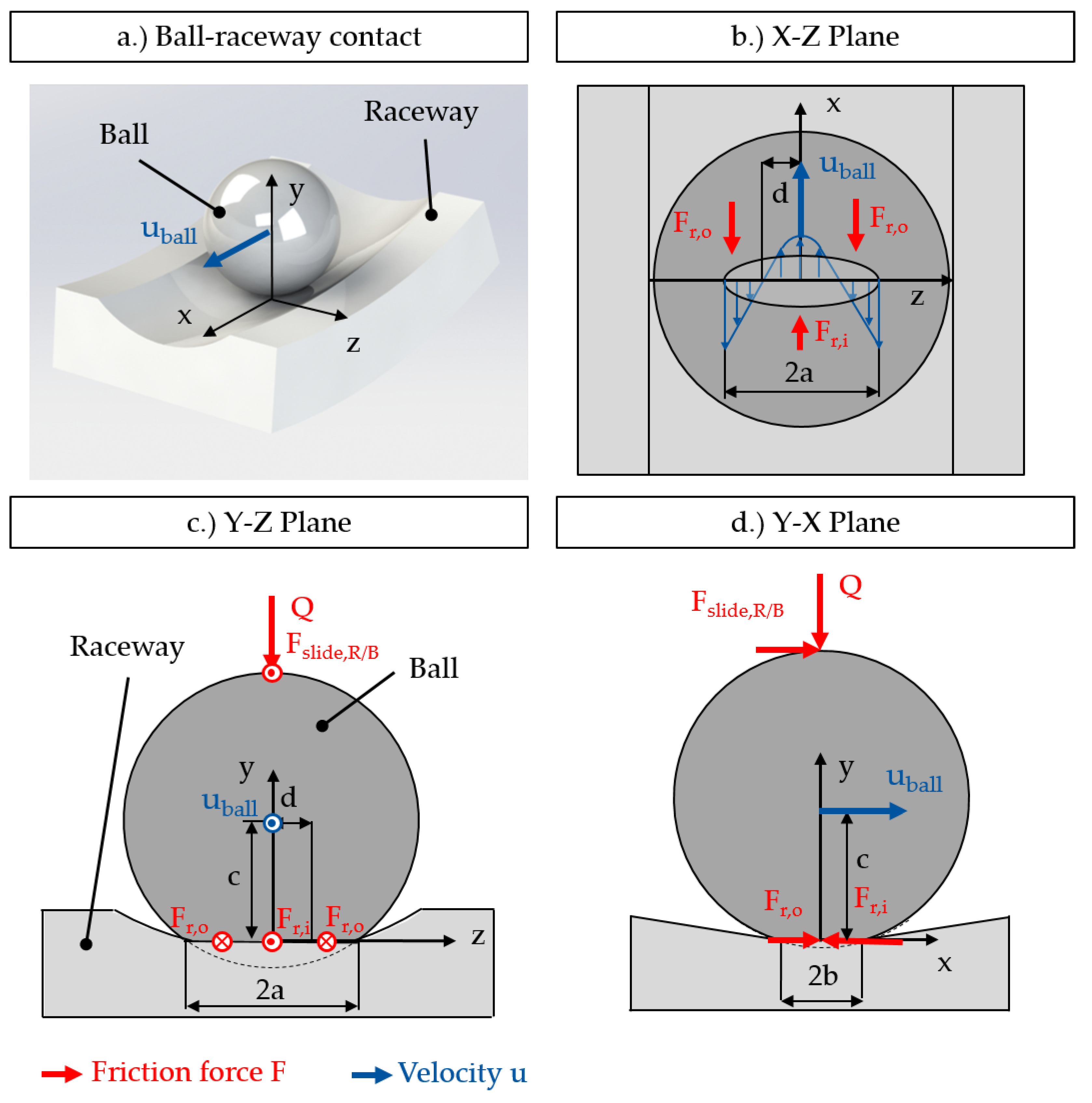
2.1.2. Raceway–Ball Sliding Friction Due to Rolling Motion
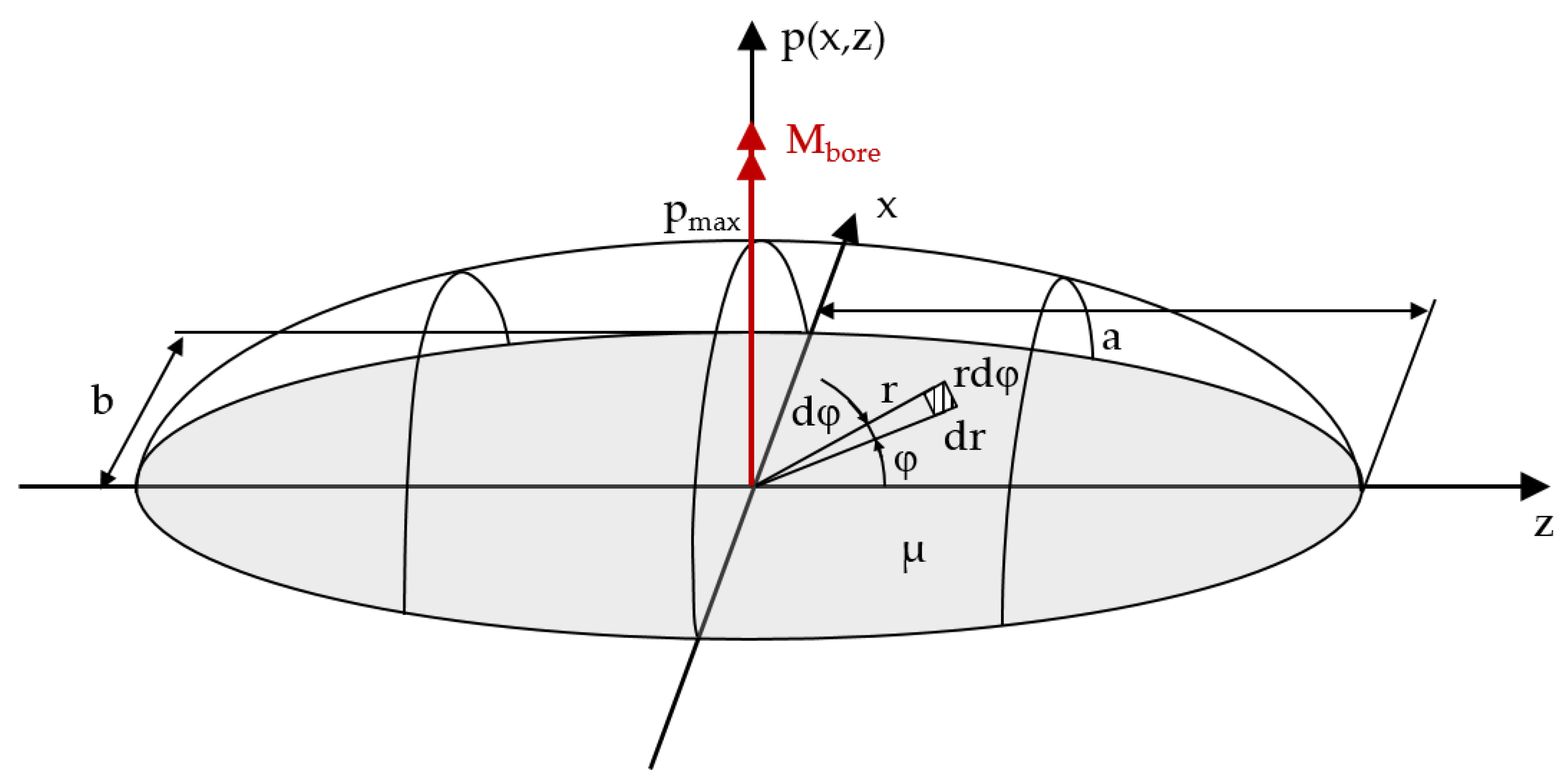
2.1.3. Raceway–Ball Bore Friction
2.1.4. Total Bearing Friction Torque
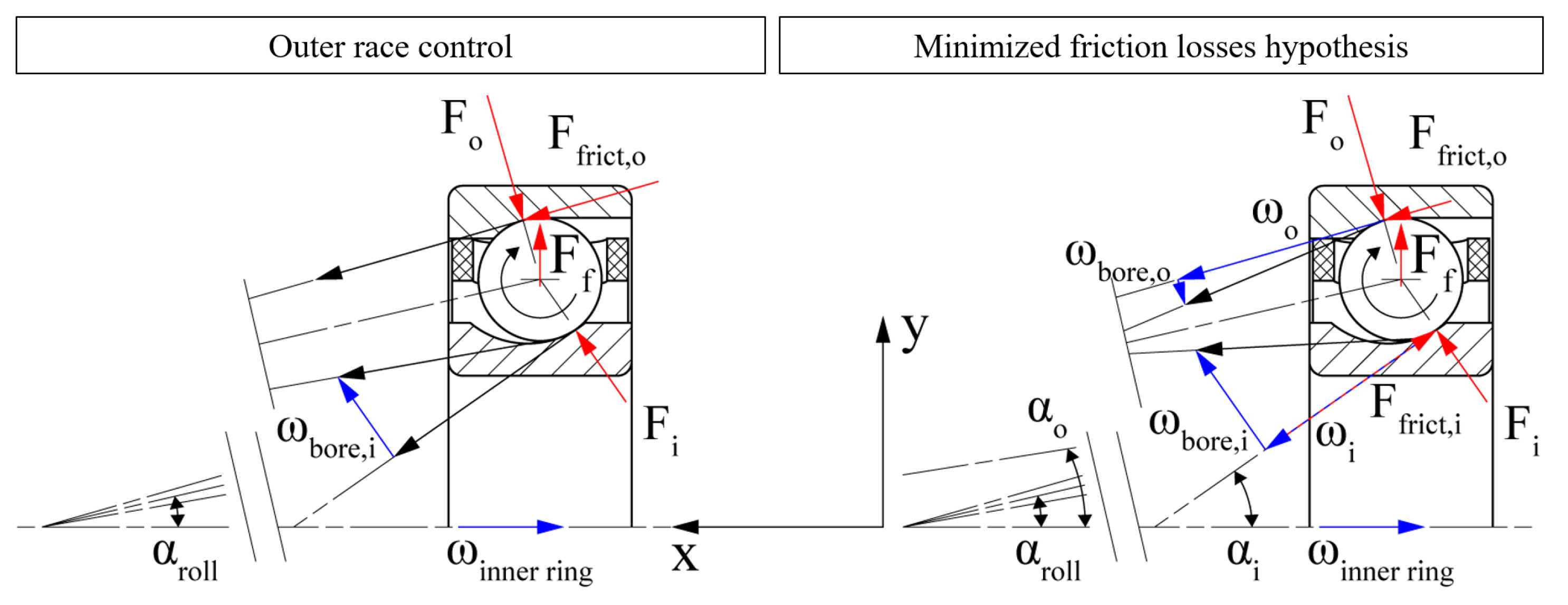
2.1.5. High-Speed Ball Motion
3. Experimental Methods
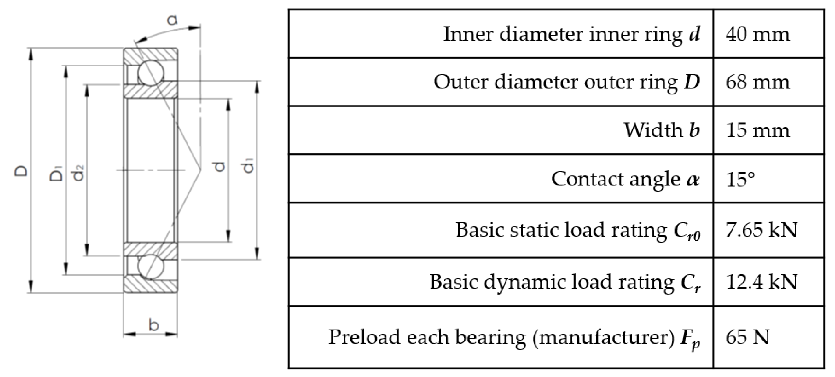
3.1. Bearings and Lubricants
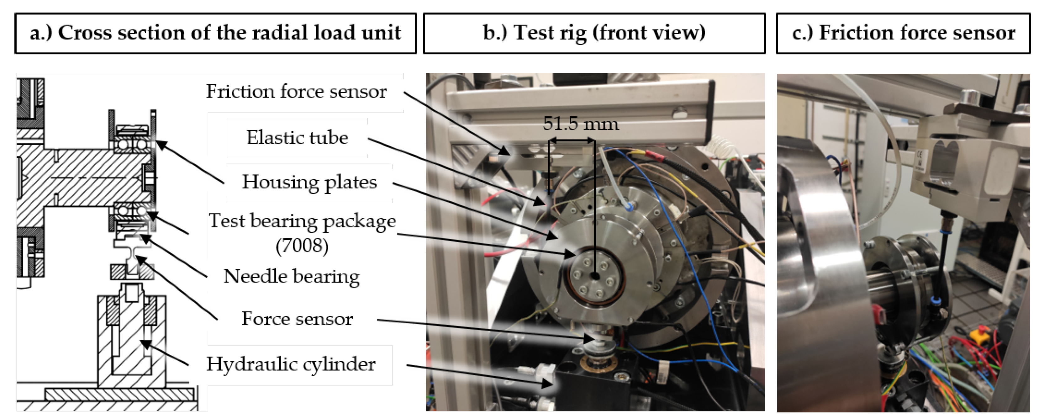
3.2. Test Setup
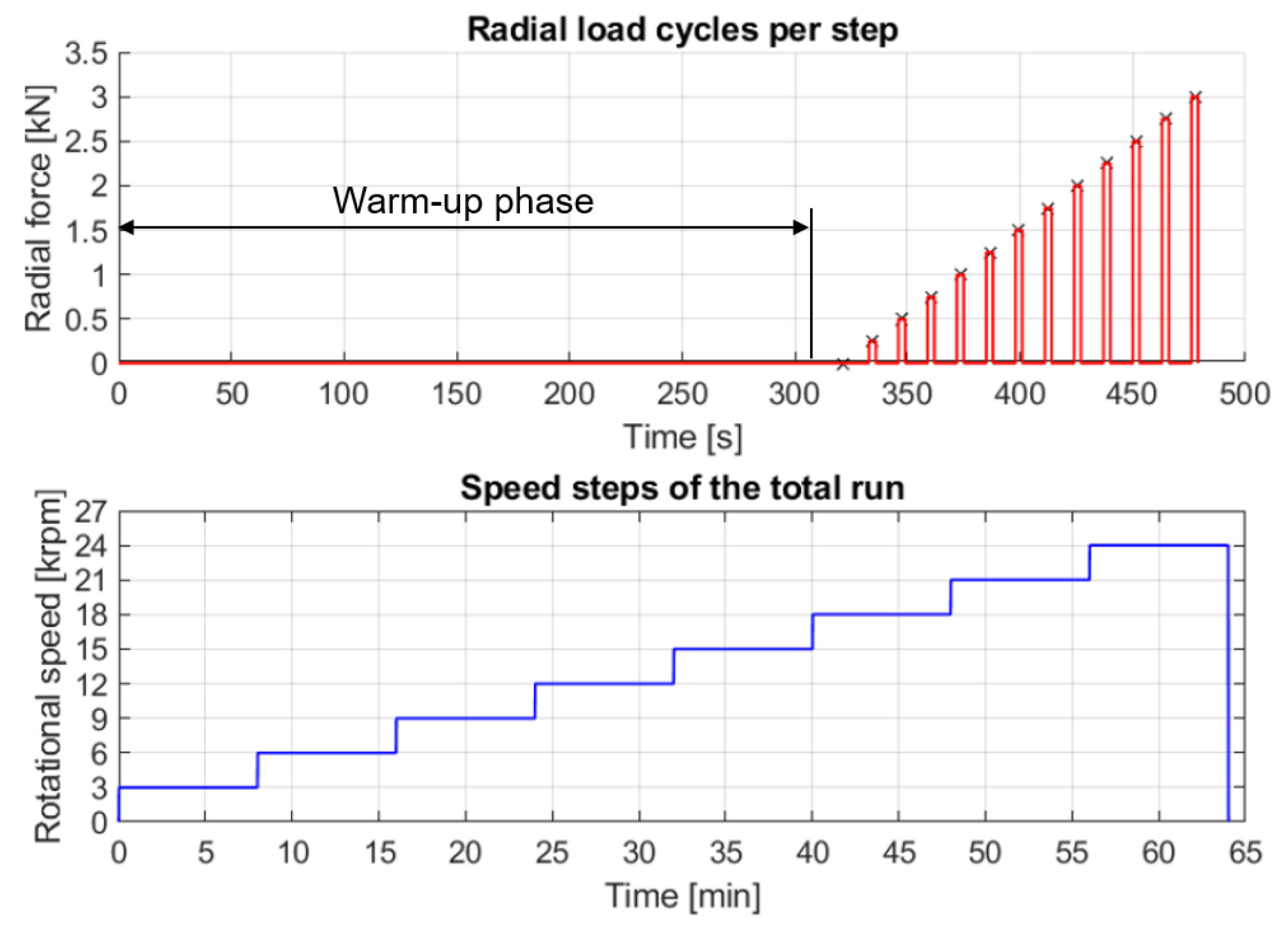
3.3. Test Program
4. Results
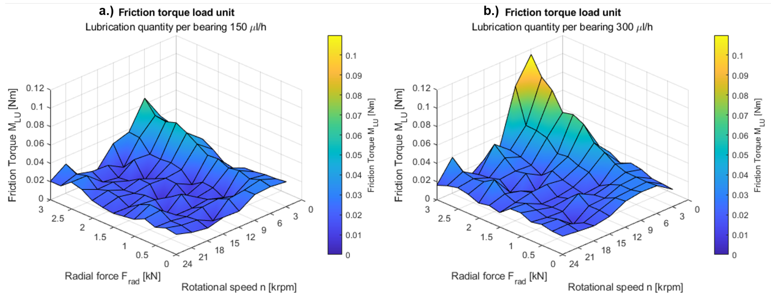
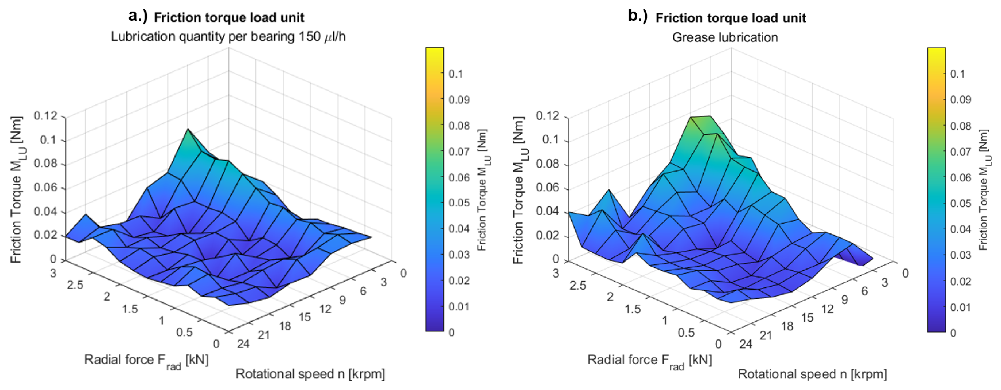
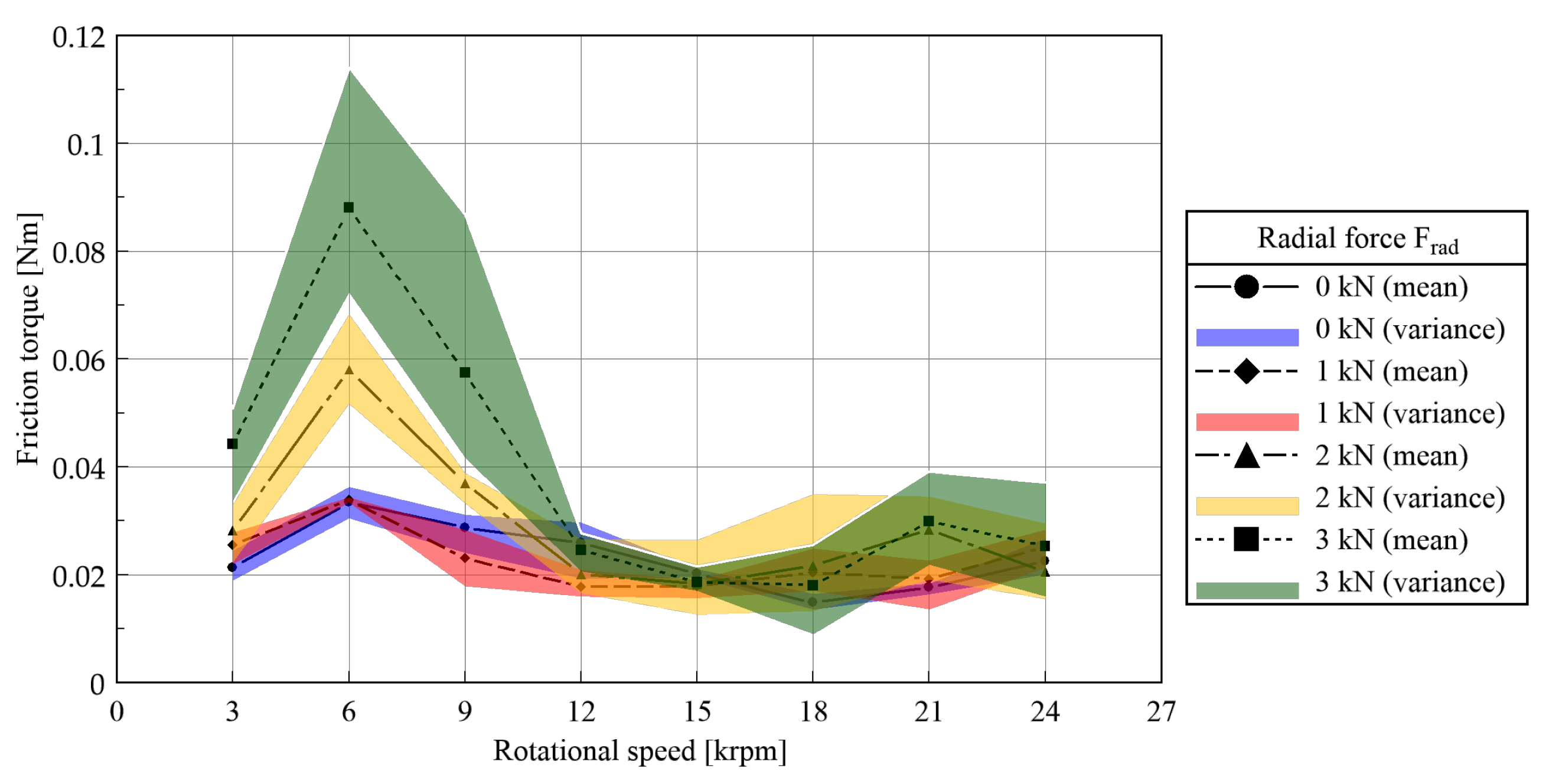
Experimental Results
5. Discussion
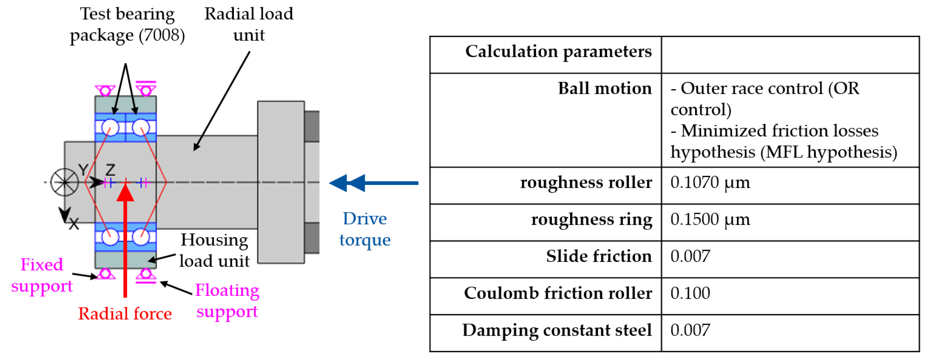
5.1. Validation of the Calculation
6. Conclusions
Author Contributions
Funding

Institutional Review Board Statement
Informed Consent Statement
Data Availability Statement
- Figure 6—Test program.csv;
- Figure 7—Bearing friction as a function of speed and radial load for different lubrication quantities.csv;
- Figure 8–Bearing friction with oil and grease lubrication.csv;
- Figure 9—Deviations of the measurements over the speed steps and radial loads for a lubrication quantity of 300 µL/h.csv;
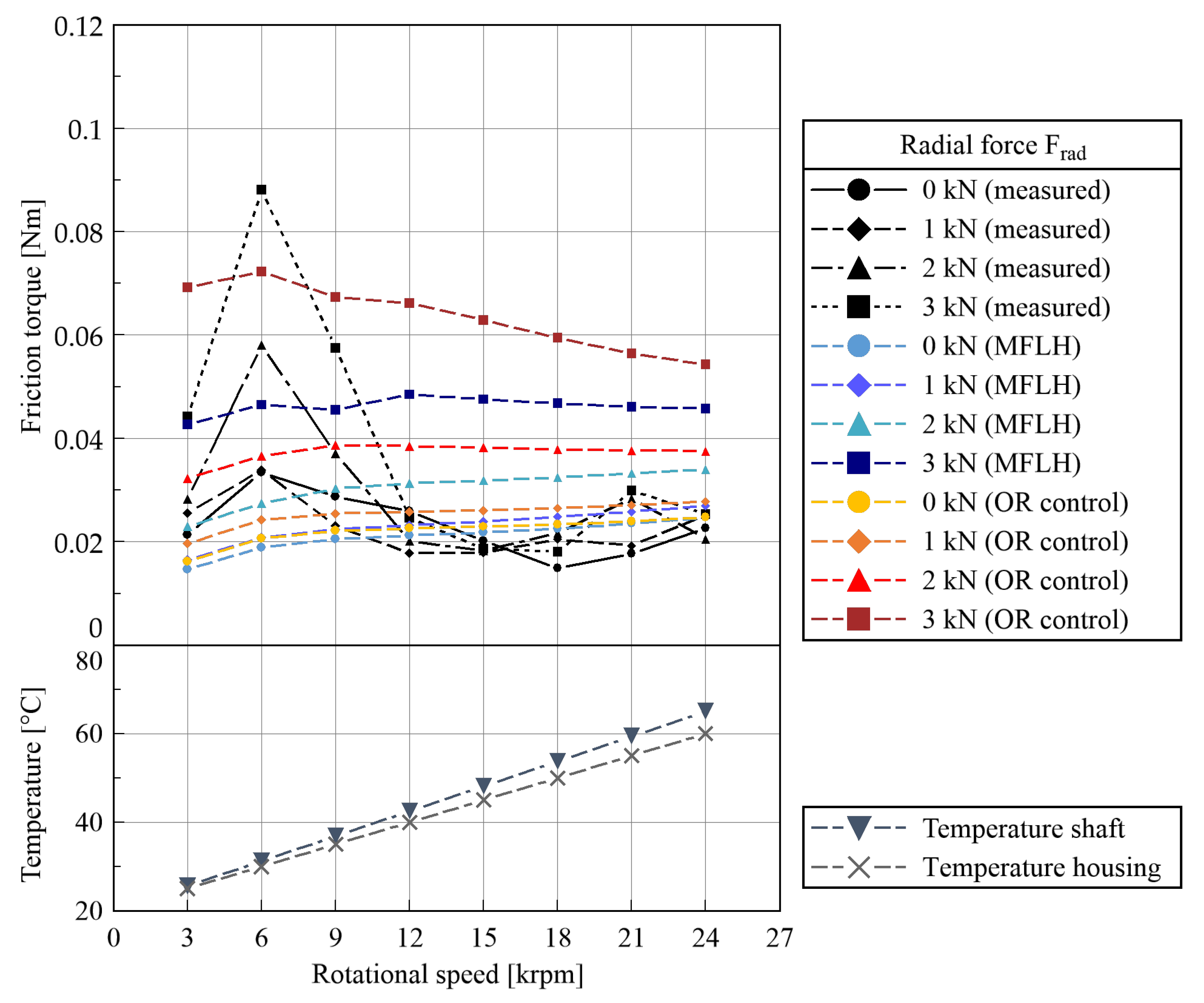
- Figure 11—Comparison of measured and calculated friction of the spindle bearing package.csv;
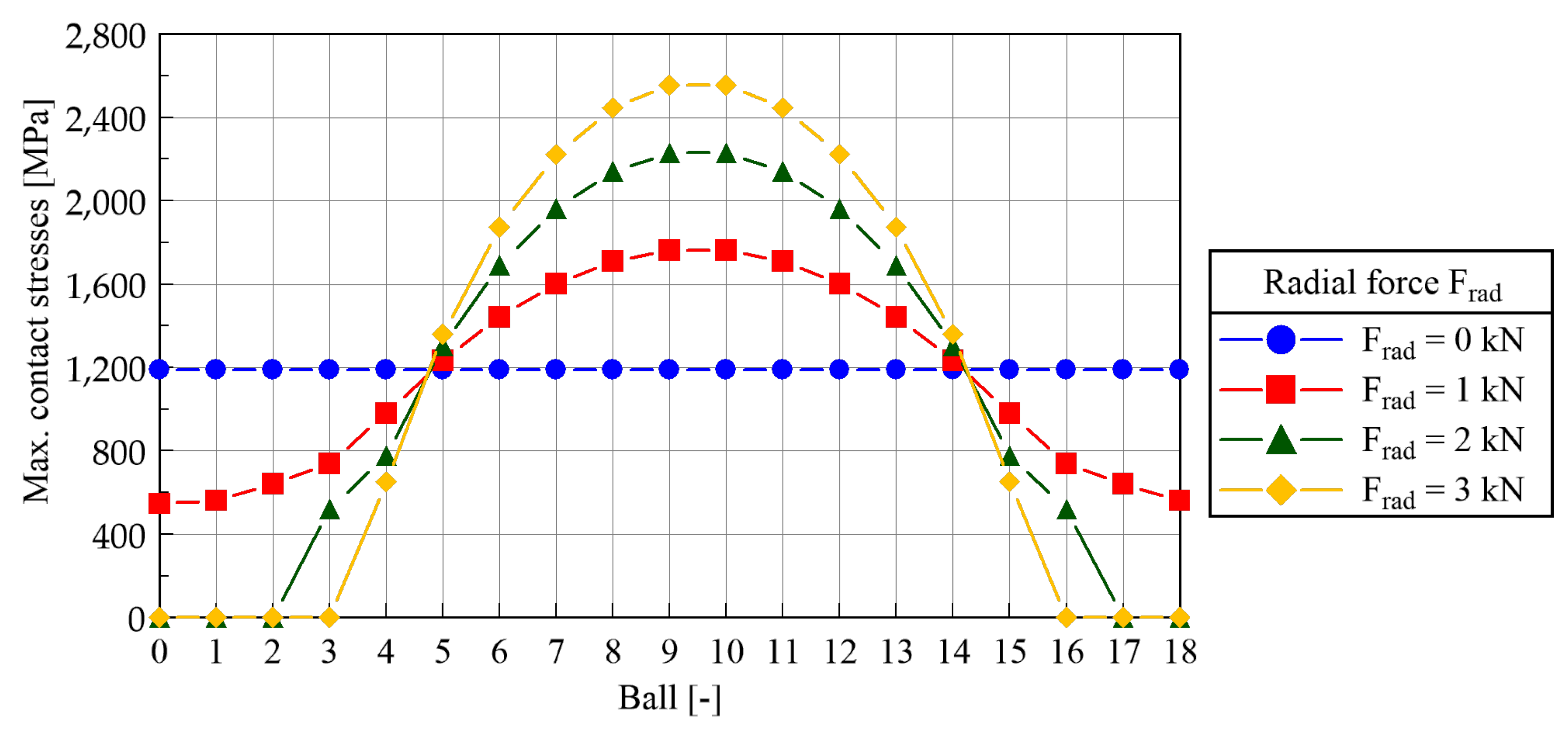
- Figure 12—Max. contact stresses at the inner raceway of the bearing for each ball and increasing radial loads.csv;
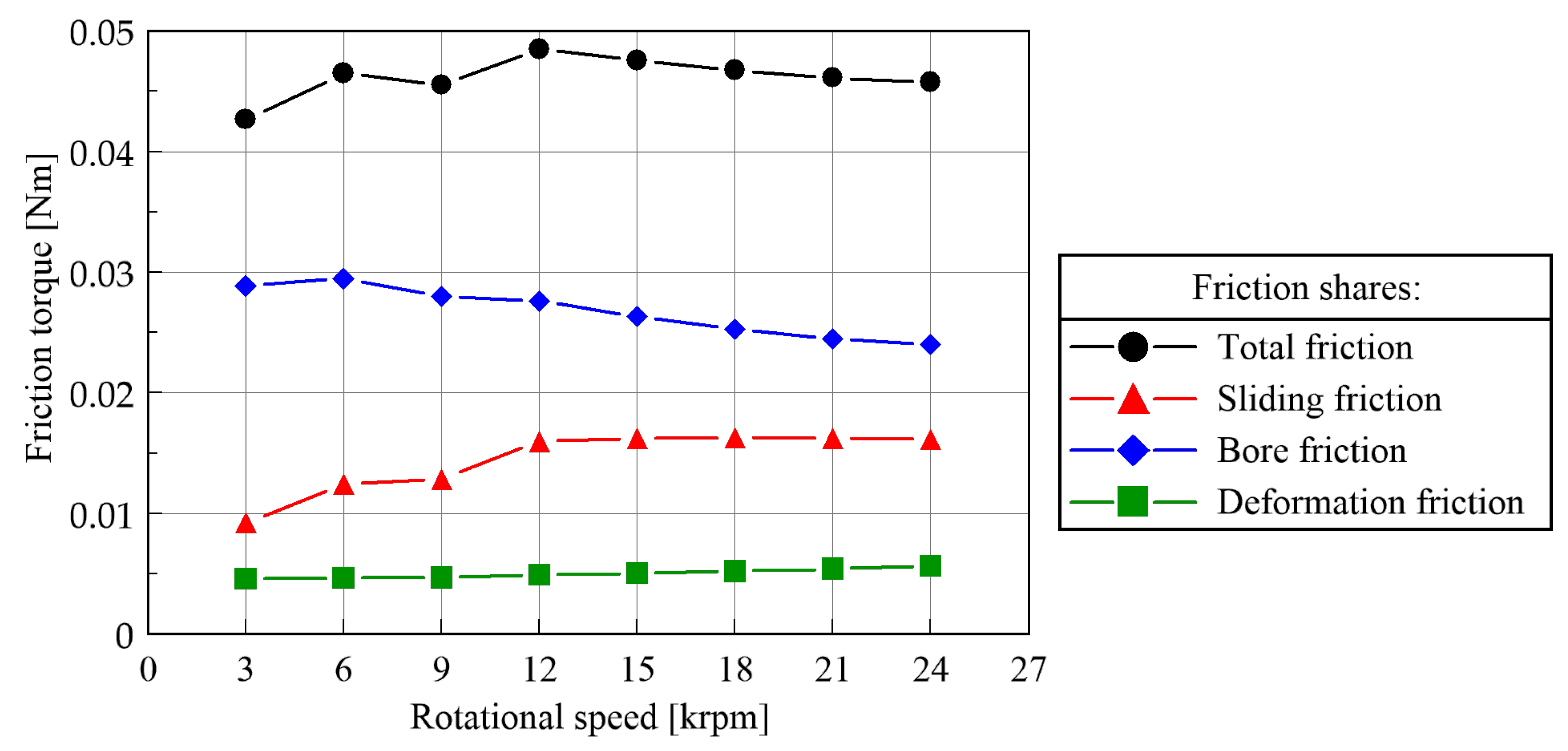
- Figure 13—Single friction shares for 3 kN radial load based on MFLH.csv.
Acknowledgments
Conflicts of Interest
Abbreviations
| WZL | Werkzeugmaschinenlabor (Laboratory for Machine Tools and Production Engineering |
| of RWTH Aachen University) | |
| EHD | Elastohydrodynamic |
| OR | Outer raceway |
| MFLH | Minimised friction loss hypothesis |
| MAGLEV | Measurement and analysis of generator bearing loads and efficiency with validation |
| CS2JU | Clean Sky 2 Joint Undertaking |
Nomenclature
| A | Area (m) |
| a | Length of the semi-axis of the pressure ellipse in the rolling contact (m) |
| b | Height of the semi-axis of the pressure ellipse in the rolling contact (m) |
| d | Distance between the point with no sliding velocities and the x-axis (m) |
| Ball diameter (m) | |
| Infinitesimal friction force (N) | |
| Coulomb friction (N) | |
| Elastohydrodynamic friction (N) | |
| Inner friction component (N) | |
| Outer friction component (N) | |
| Sliding friction (N) | |
| G | Dimensionless material parameter (-) |
| h | Temperature-independent EHD central lubricant film thickness (-) |
| Substitute variable (-) | |
| Lever arms for the friction moments (m) | |
| Total raceway–ball bore friction torque (Nm) | |
| Coulomb bore friction torque (Nm) | |
| EHD torque for the fluid friction share (Nm) | |
| Total rolling friction torque (Nm) | |
| Single rolling friction torque of the inner ring (Nm) | |
| Total raceway–ball rolling friction torque (Nm) | |
| Total raceway–ball sliding friction torque (Nm) | |
| Total bearing friction torque (Nm) | |
| High-speed parameter (m/min) | |
| Q | Normal force in the rolling contact (N) |
| Maximum pressure (N/m) | |
| R | Substituted radius (m) |
| r | Distance to the bore axis (m) |
| Auxiliary radius (m) | |
| x | Coordinate direction (rolling direction) (m) |
| U | Dimensionless speed parameter (-) |
| W | Dimensionless load parameter (-) |
| z | Coordinate direction (transverse to rolling direction) (m) |
| Pressure distribution (N/m) | |
| Viscosity (Pas) | |
| Temperature (K), (°C) | |
| Damping parameter (-) | |
| Specific lubricant film height (-) | |
| Weighting factor (-) | |
| Coulomb friction coefficient (-) | |
| Elastohydrodynamic friction coefficient (-) | |
| Hertzian coefficient of the large pressure surface semi-axis a (-) | |
| Sliding friction coefficient (-) | |
| Thermal reduction factor (-) | |
| Angle in polar coordinates (rad) | |
| Angular speed of the rolling element (s) | |
| Bore angle speed at the inner ring (s) | |
| Bore angle speed at the outer ring (s) | |
| Angular speed of the inner ring (s) | |
| Angular speed of the outer ring (s) |
References
- Steinert, T. Das Reibmoment von Kugellagern mit Bordgeführtem Käfig. Ph.D. Thesis, RWTH Aachen, Aachen, Germany, 1996. [Google Scholar]
- Rossaint, J. Steigerung der Leistungsfähigkeit von Spindellagern durch Optimierte Lagergeometrien. Ph.D. Thesis, RWTH Aachen, Aachen, Germany, November 2013. [Google Scholar]
- Wang, D. Berechnung der Wälzlagerreibung Aufgrund Weiterentwickleter Rheologischer Fluidmodelle. Ph.D. Thesis, Leibniz University Hannover, Hannover, Germany, 2015. [Google Scholar]
- Zhou, R.S.; Hoepprich, M.R. Torque of Tapered Roller Bearings. ASME J. Tribol. 1991, 113, 590–597. [Google Scholar] [CrossRef]
- Houpert, L. Ball Bearing and Tapered Roller Bearing Torquem Analytical, Numerical and Experimental Results. Tribol. Trans. 2008, 45, 345–353. [Google Scholar] [CrossRef]
- Tong, V.C.; Hong, S.W. Improved formulation for running torque in angular contact ball bearings. Int. J. Precis. Eng. Manuf. 2018, 19, 47–56. [Google Scholar] [CrossRef]
- Brecher, C.; Neus, S.; Gärtner, M.; Eckel, H.M.; Hoppert, M.; James, B.; Gerada, C.; Degano, M.; Ilkhani, M.R.; Di Nardo, M. Design of an Aircraft Generator with Radial Force Control; Open Research Europe: London, UK, 2022. [Google Scholar]
- DIN. Mechanisch-Dynamische Prüfung auf dem Wälzlagerschmierstoff-Prüfgerät FE8: Teil 1: Allgemeine Arbeitsgrundlagen, December 2016. Available online: https://www.beuth.de/de/norm/din-51819-1/262168002 (accessed on 14 March 2023).
- Harris, T.A.; Kotzalas, M.N. Advanced Concepts of Bearing Technology: Rolling Bearing Analysis, 5th ed.; CRC Press: Boca Raton, FL, USA, 2007. [Google Scholar]
- Hertz, H. Ueber die Berührung fester elastischer Körper. J. Für Die Reine Angew. Math. (Crelles J.) 1882, 91, 156–171. [Google Scholar]
- Tood, M.J.; Johnsons, K.L. A model for coulomb torque hysteresis in ball bearings. Int. J. Mech. Sci. 1987, 29, 339–354. [Google Scholar] [CrossRef]
- Hoischen, H. Technisches Zeichnen, 38th ed.; Cornelsen: Essen, Germany, 2022. [Google Scholar]
- Chittenden, R.J.; Dowson, D.; Dunn, J.F.; Taylor, C.M.; Johnson, K.L. A theoretical analysis of the isothermal elastohydrodynamic lubrication of concentrated contacts. I. Direction of lubricant entrainment coincident with the major axis of the Hertzian contact ellipse. Proc. R. Soc. Lond. A Math. Phys. Sci. 1985, 397, 245–269. [Google Scholar] [CrossRef]
- Gohar, R. Oil Film Thickness and Rolling Friction in Elastohydrodynamic Point Contact. J. Lubr. Technol. 1971, 93, 371–379. [Google Scholar] [CrossRef]
- Bahadoran, H.; Gohar, R. The oil film in elastohydrodynamic elliptical contacts. Wear 1974, 29, 264–270. [Google Scholar] [CrossRef]
- Bronstein, I.N.; Semendjajew, K.A. Taschenbuch der Mathematik, 11th ed.; Europa-Lehrmittel: Haan, Germany, 2020. [Google Scholar]
- Grekoussis, T.R.; Michailidis, M.R. Näherungsgleichung zur Nach- und Entwurfsrechnung der Punktberührung nach Hertz. Konstruktion 1988, 33, 135–139. [Google Scholar]
- Deulin, E.A.; Mikhailov, V.P.; Panfilov, Y.V.; Nevshupa, R.A. Mechanics and Physics of Precise Vacuum Mechanisms; Fluid Mechanics and Its Applications; Springer: Dordrecht, The Netherlands, 2012. [Google Scholar]
- Brecher, C.; Rossaint, J.; Hassis, A. Cage Friction in High-Speed Spindle Bearings. Tribol. Trans.-Off. J. Soc. Tribol. Lubr. Eng. 2014, 57, 77–85. [Google Scholar] [CrossRef]
- Hong, S.W.; Tong, V.C. Rolling-element bearing modeling: A review. Int. J. Precis. Eng. Manuf. 2016, 17, 1729–1749. [Google Scholar] [CrossRef]
- Tüllmann, U. Das Verhalten Axial Verspannter, Schnelldrehender Schrägkugellager. Ph.D. Thesis, RWTH Aachen, Aachen, Germany, 1999. [Google Scholar]
- Gupta, P.K. Minimum Energy Hypothesis in Quasi-Static Equilibrium Solutions for Angular Contact Ball Bearings. Tribol. Trans. 2020, 63, 1051–1066. [Google Scholar] [CrossRef]
- Falker, J. Analyse des Betriebsverhaltens von Hochgeschwindigkeits-Wälzlagern unter Radialen Lasten. Ph.D. Thesis, RWTH Aachen, Aachen, Germany, 2019. [Google Scholar]
- SKF. Super-Precision Bearings; SKF: Gothenburg, Sweden, 2014. [Google Scholar]
- Klüber. Klübersynth FB 4-32, 4-46, 4-68. Munich, 2021. Available online: https://www.klueber.com/de/de/downloads (accessed on 12 March 2023).
- Klüber. Klüberspeed BF 72-22. Munich, 2020. Available online: https://www.klueber.com/de/de/downloads (accessed on 15 March 2023).
- Gärtner, M.; Brecher, C.; Neus, S.; Eckel, H.M.; Bartelt, A.; Hoppert, M.; Ilkhani, M.R. The Friction of Radially Loaded Hybrid Spindle Bearings under High Speeds. 2023. Available online: https://zenodo.org/record/7986707 (accessed on 1 March 2023).
- Brecher, C.; Bartelt, A.; Fey, M.; Hassis, A.; Lehner, B. Einflussfaktoren auf das Reibmoment Öl-Luft-geschmierter Spindellager. Tribol. Schmier. 2018, 65, 26–30. [Google Scholar]
- Brecher, C.; Weck, M. (Eds.) Machine Tools Production Systems 2: Design, Calculation and Metrological Assessment; Springer: Berlin/Heidelberg, Germany, 2021; Volume 2. [Google Scholar] [CrossRef]
- Brecher, C.; Fey, M.; Falker, J. Simulation schnelldrehender Wellen-Lager-Systeme -Teil 1: Berechnung von Hochgeschwindigkeitswälzlagern in Wellen-Lager-Systemen. Antriebstechnik 2019, 58, 66–72. [Google Scholar]
- Schulz, A.; Körner, G. NewSpilad Version 1.0c—Berechnungsprogramm des Werkzeugmaschinenlabors der RWTH Aachen. Technical Report. 2002. Available online: https://books.google.de/books?id=kmMhBAAAQBAJ&pg=PA687&lpg=PA687&dq=NewSpilad+Version+1.0c---Berechnungsprogramm+des++Werkzeugmaschinenlabors&source=bl&ots=kYYCgm3_Hh&sig=ACfU3U0vVznsunYGTSQYoL4piob50g2cVw&hl=en&sa=X&ved=2ahUKEwiC6cj3pcP_AhURxwIHHUn6CV0Q6AF6BAgIEAM#v=onepage&q=NewSpilad (accessed on 20 March 2023).
- Butz, F.; Tüllmann, U. WinLager2v0—Berechnungsprogramm des Werkzeugmaschinenlabors der RWTH Aachen. Technical Report. 2003. Available online: https://books.google.de/books?id=kmMhBAAAQBAJ&pg=PA687&lpg=PA687&dq=NewSpilad+Version+1.0c---Berechnungsprogramm+des++Werkzeugmaschinenlabors&source=bl&ots=kYYCgm3_Hh&sig=ACfU3U0vVznsunYGTSQYoL4piob50g2cVw&hl=en&sa=X&ved=2ahUKEwiC6cj3pcP_AhURxwIHHUn6CV0Q6AF6BAgIEAM#v=onepage&q=NewSpilad (accessed on 20 March 2023).
- Wang, L.; Wood, R.; Harvey, T.; Morris, S.; Powrie, H.; Care, I. Wear performance of oil lubricated silicon nitride sliding against various bearing steels. Wear 2003, 255, 657–668. [Google Scholar] [CrossRef]


Disclaimer/Publisher’s Note: The statements, opinions and data contained in all publications are solely those of the individual author(s) and contributor(s) and not of MDPI and/or the editor(s). MDPI and/or the editor(s) disclaim responsibility for any injury to people or property resulting from any ideas, methods, instructions or products referred to in the content. |
© 2023 by the authors. Licensee MDPI, Basel, Switzerland. This article is an open access article distributed under the terms and conditions of the Creative Commons Attribution (CC BY) license (https://creativecommons.org/licenses/by/4.0/).
Share and Cite
Gärtner, M.; Brecher, C.; Neus, S.; Eckel, H.-M.; Bartelt, A.; Hoppert, M.; Ilkhani, M.R. The Friction of Radially Loaded Hybrid Spindle Bearings under High Speeds. Machines 2023, 11, 649. https://doi.org/10.3390/machines11060649
Gärtner M, Brecher C, Neus S, Eckel H-M, Bartelt A, Hoppert M, Ilkhani MR. The Friction of Radially Loaded Hybrid Spindle Bearings under High Speeds. Machines. 2023; 11(6):649. https://doi.org/10.3390/machines11060649
Chicago/Turabian StyleGärtner, Marcus, Christian Brecher, Stephan Neus, Hans-Martin Eckel, Andreas Bartelt, Maik Hoppert, and Mohammad Reza Ilkhani. 2023. "The Friction of Radially Loaded Hybrid Spindle Bearings under High Speeds" Machines 11, no. 6: 649. https://doi.org/10.3390/machines11060649
APA StyleGärtner, M., Brecher, C., Neus, S., Eckel, H.-M., Bartelt, A., Hoppert, M., & Ilkhani, M. R. (2023). The Friction of Radially Loaded Hybrid Spindle Bearings under High Speeds. Machines, 11(6), 649. https://doi.org/10.3390/machines11060649