Abstract
The contact form of the orbiting scroll and Oldham’s coupling plays an important role in improving the operation stability of the scroll compressor. In this study, the kinematic simulation of key moving parts such as the orbiting scroll and Oldham’s coupling was carried out under the condition of low speed, and the reason for the impact between Oldham’s coupling and the orbiting scroll was revealed. Results showed that the clearance between the moving pairs causes the orbiting scroll to have a slight rotation tendency and causes the impact between Oldham’s coupling and the orbiting scroll. The angular velocity of the orbiting scroll in the x-axis direction can effectively characterize this impact. The impact of the Oldham’s coupling convex key on the mainframe keyway is more severe than that on the keyway of the orbiting scroll. By optimizing the structure of the convex key of Oldham’s coupling, the contact form between Oldham’s coupling and the orbiting scroll is improved, and the starting acceleration of the orbiting scroll is reduced by 53%, which greatly improved the working stability of the scroll compressor.
1. Introduction
The scroll compressor is a kind of displacement air compressor, and compared with the traditional piston compressor, the scroll compressor has fewer parts and higher reliability. Without the constraint of complex parts, the scroll compressor eliminates the violent collision between the valve plate and the compressed high-pressure gas, which means it has the characteristics of low vibration, low noise, and high efficiency [1,2,3]. It is therefore widely used in air conditioning refrigeration, engine supercharging, and other fields [4,5,6]. The core components of the scroll compressor are composed of the fixed scroll and the orbiting scroll, which carry out suction, compression, and exhaust work through the meshing of each other, and input or output mechanical power through the crankshaft. The profile characteristics and motion features of the orbiting scroll directly affect the performance of the scroll compressor [7,8]. During the operation of the scroll compressor, the orbiting scroll moves horizontally around the fixed scroll, and its meshing position changes with the change in the crankshaft angle. In order to ensure the working performance and stability of the scroll compressor, it is necessary to conduct a simulation study on the kinematic characteristics of the orbiting scroll.
Virtual prototype simulation is an effective method to analyze the motion feature of mechanical systems [9,10]. Researchers previously carried out a simulation study on the motion process of the scroll compressor, whereby Qiang et al. [11] studied the dynamic characteristics of the orbiting scroll by using a self-established dynamic model of the scroll compressor and predicted the volumetric efficiency and compression efficiency of the scroll mechanism. Feng [12] studied the dynamic performance of the scroll compressor based on theoretical methods and calculated the gas force and torque of the moving parts. Considering the gas force, centrifugal force, bearing force, and contact force, Kim [13] carried out four degrees of freedom dynamic analysis of the axle neck supported by the journal of the scroll compressor, and the correctness of the analysis results was verified by comparing them with the commercial program. Hiwata [14] studied the dynamic characteristics of the CO2 refrigerant scroll compressor and found that the contact force between the fixed scroll and the orbiting scroll is related to the changes in motor speed, pressure, and temperature in the working chamber. Ahn [15,16] studied the dynamic characteristics of the orbiting scroll and the crankshaft considering the gas force on the orbiting scroll and analyzed the lubrication characteristics of the radial bearing supporting the crankshaft in the scroll compressor. Msk [17] established a dynamic model of the thrust bearing of the scroll compressor but did not consider the impact of the collision between the keyway of the orbiting scroll and the key of Oldham’s coupling on the orbiting scroll and the thrust bearing.
When the scroll compressor is running, to achieve the correct meshing of the scroll and prevent the rotation of the orbiting scroll, it is necessary to set up an anti-rotation mechanism [18]. Common anti-rotation mechanisms of the scroll compressor include Oldham’s coupling, the roller [19], and sub-crankshafts; among them, Oldham’s coupling anti-rotation mechanism has been widely used because of its simple structure, convenient manufacturing and installation, good reliability, and other characteristics [20]. During the operation of the scroll compressor, Oldham’s coupling reciprocates along the keyway of Oldham’s coupling and the mainframe, and its dynamic characteristics have a great influence on the reliability and durability of the scroll compressor. Bell [21] and Ziviani [22] developed an open-source modeling platform for a positive displacement compressor, which can be used to analyze the wear of Oldham’s coupling, thrust bearings, and other mechanisms, Machekposhti [23] proposed a flexible dynamic transmission mechanism between parallel rotating shafts based on the rigid body model of Oldham’s coupling, which corrects the lateral offset between two parallel rotating shafts. Henri [24] analyzed and verified the dynamic performance of this transmission mechanism. When the scroll compressor is running, the motion trajectory of Oldham’s coupling is closely related to the orbiting scroll. In the study of the dynamic characteristics of the scroll compressor, the motion of the orbiting scroll is often compared with Oldham’s coupling.
In order to explore the operation mechanism of the main moving parts of the scroll compressor and reduce the impact vibration between the convex key of Oldham’s coupling and the keyway of the orbiting scroll, by analyzing the motion state and motion law of the orbiting scroll and Oldham’s coupling, the kinematic characteristics of the main moving parts of the scroll compressor were deeply explored. The velocity change data of the orbiting scroll in x- and y-directions derived from Adams were fitted by Matlab; thereby, the existence of the initial phase angle of the orbiting scroll velocity variation equation was revealed. The convex key structure of Oldham’s coupling was improved, which greatly reduces the contact impact between the moving parts of the scroll compressor and improves the working reliability of the scroll compressor. The results provide a reference for the optimal design and kinematic behavior prediction of the scroll compressor.
2. Structural Model
When studying the motion characteristics of the scroll compressor during the meshing process, the crank-slider mechanism can be used to represent the relative motion position relationship of the orbiting and fixed scrolls during operation. As shown in Figure 1, point A is on the orbiting scroll at a certain working position and point B is the point corresponding to point A at the center of the revolution. In Figure 1, the fixed scroll and the mainframe can be regarded as a fixed part, and the constraint of Oldham’s coupling is simplified as the constraint of slider 1 and slider 2. When the orbiting scroll and fixed scroll mesh, there is a definite meshing point A; this position constitutes a virtual constraint, and the orbiting scroll can only perform translational motion around the fixed scroll under the constraint of the slider. The number of active components in this mechanism is 3 and the number of low-level vices is 4, while the virtual constraints are not substituted into the calculation. According to the calculation of Formula (1), the degree of freedom of the mechanism is 1, and the motion characteristics are determined.
where F is the degree of freedom, n is the number of moving components, pl is the number of low pairs, and ph is the number of high pairs.
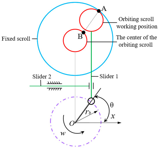
Figure 1.
Crank-slider mechanism diagram of scroll compressor.
To determine the position coordinates of the orbiting scroll at a certain moment, we take the orbiting center position (x, y) and a certain meshing position (X, Y) of the orbiting scroll, and Equation (2) can express its motion position relationship.
where θ is the crank angle and ψ is the angle parameter.
For the orbiting scroll, which the scroll profile developed from the base circle, the position coordinates of its centroid can be calculated by Formulas (3) and (4):
The centroid position of the orbiting scroll affects the accuracy of analyzing the motion trajectory of the scroll, resulting in a secondary balance error. Therefore, it is necessary to balance the centroid of the orbiting scroll. The balance of the scroll compressor is divided into the static balance of the orbiting scroll and the dynamic balance of the rotor system. The static balance is to return the axis of the centroid of the orbiting scroll to the same axis of the scroll tooth base circle, as shown in Figure 2a. F is the rotational inertial force, F’ is the inertial force generated by the rotation of the balance block, and there is a certain distance between F and F’, which causes the orbiting scroll to tend to overturn. The overturning moment can only be weakened by a reasonable design and cannot be eliminated. Dynamic balancing is the return of the centroid of the orbiting scroll to the axis of the centroid of the main drive shaft. In this paper, the material removal method is used to reduce the inertia force generated by the orbiting scroll, solve the space problem of the static balance eccentric block, and reduce the overturning arm as much as possible.
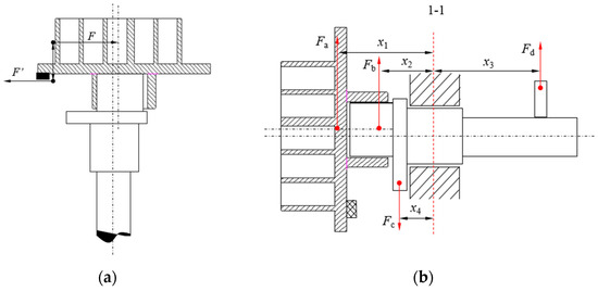
Figure 2.
Mechanical equilibrium model. (a) Static balance. (b) Dynamic balance.
As shown in Figure 2b, the force balance analysis is carried out based on 1-1. Fa is the rotating inertial force of the orbiting scroll after static balance, Fb and Fc are the eccentric rotating inertial forces of the crankshaft, and Fd is the rotational inertia force of the balance block. The inertial force and inertial moment satisfy the following equations.
During the operation of the scroll compressor, the orbiting scroll moves in translation around the fixed scroll, and its meshing position changes with the change of the crankshaft rotation angle. The motion characteristics of the orbiting scroll and Oldham’s coupling directly affect the working condition of the scroll compressor. To ensure the working performance and stability of the scroll compressor, it is necessary to simulate the kinematic characteristics of the orbiting scroll. As shown in Figure 3, the scroll compressor can be reasonably simplified without affecting the motion analysis, and its kinematic characteristics can be studied through Adams.
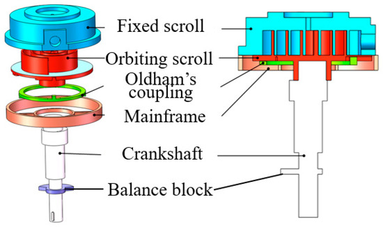
Figure 3.
Schematic of the scroll compressor.
3. Kinematics Analysis of the Orbiting Scroll
3.1. Virtual Prototype Model
Through the Adams View simulation platform, the kinematic simulation analysis of the scroll compressor can be realized in a visual environment. The scroll compressor power source is a constant speed output during operation. During the virtual prototype simulation process, the drive is set at the end of the crankshaft, and the STEP displacement function is used to control the rotation. To better characterize the working parts’ motion form and the working state of the scroll compressor, we set the drive function to −360.0 d*time. When the scroll compressor is in operation, the orbiting scroll is the driving member, Oldham’s coupling is the driven member, and Oldham’s coupling has a constraining effect on the movement trajectory of the orbiting scroll.
Adams Solver uses the IMPACT function to calculate the contact impact force. The IMPACT function model equals the actual object collision process as a nonlinear spring-damping model based on the penetration depth. To prevent the discontinuity of the damping force during the collision process, the STEP function is used to define the damping. The theoretical calculation formula of the collision model is:
where K is the stiffness coefficient, δ is the penetration depth between the contacting objects, n is the force index of the collision material, Cmax is the maximum damping coefficient, and dmax is the penetration boundary depth.
3.2. Analysis of the Orbiting Scroll Motion State
Before the motion simulation, we adjust the crankshaft rotation angle θ, take the center of the fixed scroll base circle as the origin, and define the coordinate of the orbiting scroll base circle center (−Ror, 0) while θ = 0°. Figure 4 shows the relative motion positions between the orbiting scroll, Oldham’s coupling, and the fixed scroll under different crankshaft rotation angles. When the crankshaft rotation angle θ is 0° and 180°, Oldham’s coupling convex keys are in the limited position of the keyway of the orbiting scroll. When the crankshaft rotation angle θ is 90° and 270°, the convex key of Oldham’s coupling is in the limited position of the keyway of the mainframe. In the operation process of the scroll compressor, the crescent-shaped closed cavity formed by the meshing of scroll teeth is constantly changing, so the process of gas inhalation, compression, and discharge is carried out at the same time, which is one of the reasons the working efficiency of the scroll compressor is higher than that of other compressors.
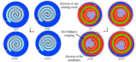
Figure 4.
Relative position relationship between the orbiting scroll, Oldham’s coupling, and the fixed scroll.
After the Adams simulation results are processed, the motion track of the orbiting scroll’s centroid position can be obtained by synthesizing the data of x, y, and z components, as shown in Figure 5. The synthesis formula of centroid position and velocity component is shown in Equation (8), which more intuitively reflects the real change of velocity and position of the orbiting scroll in space.
where vx, vy, and vz represent the velocity components of the centroid in the x, y, and z coordinate axes, respectively, in units of m/s. lx, ly, and lz represent the position components of the centroid in the x, y, and z coordinate axes, respectively, and the unit is m.
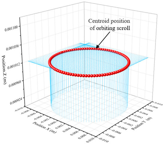
Figure 5.
3D figure of centroid position of orbiting scroll plate.
By analyzing Figure 5 it can be obtained that the z-axis value of the vertical line of the orbiting scroll centroid projection does not change, indicating that the orbiting scroll does not have axial movement. According to the matching relation, the absolute motion of the orbiting scroll is synthesized by the constrained translation of Oldham’s coupling relative to the mainframe and the constrained translation of the orbiting scroll relative to Oldham’s coupling. When the orbiting scroll rotates around the center of the mainframe, the motion equation of its centroid position can be expressed by Formula (9). The radius of the orbiting scroll’s centroid is 8.43 mm, which is consistent with the design parameters of the rotary radius.
where r is the radius of the base circle.
The velocity variation data of the orbiting scroll mass center obtained by ADAMS were imported into Origin, and the velocity variation rule of the orbiting scroll mass center was further analyzed by adjusting the numerical range of the ordinate, as shown in Figure 6. It can be seen from Figure 6 that the orbiting scroll has an acceleration phenomenon during the start-up phase, and 6 s after starting, the centroid velocity is stably maintained at approximately 5.295854 × 10⁻² m/s; periodic fluctuations occur with time, and the change period is approximately 1.0 s.
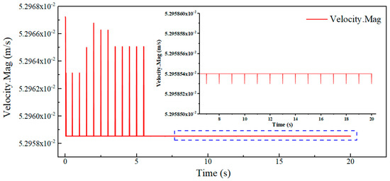
Figure 6.
Centroid velocity curve of orbiting scroll.
To further explore the change law of the centroid velocity of the orbiting scroll, the time-varying curves of the velocity and acceleration components of the orbiting scroll in the x-axis direction are analyzed. As shown in Figure 7, the speed change curve of the orbiting scroll in the x-axis direction is sinusoidal, and its acceleration change has a sudden change value. This is because when the convex key of Oldham’s coupling moves to the limit position of the keyway of the orbiting scroll, the acceleration change curve of the orbiting scroll is at its peak value and has a sudden change. At this time, the fastest speed changes.
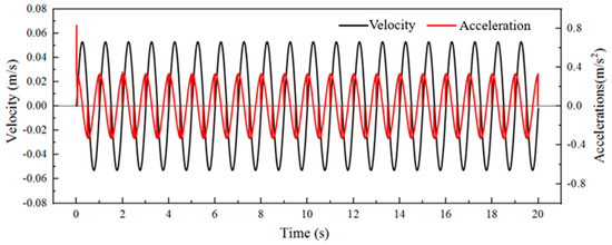
Figure 7.
Variation curves of velocity and acceleration components in the x-direction of orbiting scroll.
Figure 8 and Figure 9 show the change of the angular velocity in the x- and y-directions of the orbiting scroll within 20 s, respectively. It can be seen from these figures that the orbiting scroll accelerates during the startup phase, and approximately 6 s after startup, the angular velocity of the rear centroid in the x-direction is maintained at approximately 5.15180 × 10⁻¹⁵°/s, and the angular velocity in the y-direction of the centroid is maintained at approximately 2.88397 × 10⁻¹⁴°/s. It periodically changes slightly with time, and the change period is 1.0 s. When the rotation angle is 0° and 180°, the convex key of Oldham’s coupling is at the limit position of the keyway of the orbiting scroll. At this time, the acceleration of the orbiting scroll is the largest. The keyway first contacts an edge of the convex key of Oldham’s coupling and then tightens the stick to the side where the convex key is stressed, thereby driving Oldham’s coupling to move. When the keyway of the orbiting scroll just touches the convex key of Oldham’s coupling, the orbiting scroll and Oldham’s coupling will collide slightly, resulting in an extremely small sudden change in the angular velocity of the orbiting scroll. The existence of the angular velocity indicates that the orbiting scroll motion state has extremely small rotational motion and shock vibration. This is because the fit between the convex key of Oldham’s coupling and the keyway of the orbiting scroll is a clearance fit, and the angular velocity of the orbiting scroll in the x- and y-directions shows a sudden change every half-cycle (the convex key of Oldham’s coupling is close to the keyway of the orbiting scroll), resulting in the existence of an initial phase angle in the orbiting scroll velocity fitting equation. Since the value of the initial phase angle is very small, it can be ignored. Setting a reasonable gap between the orbiting and fixed scrolls can avoid serious wear caused by their interference. Therefore, the convex key of Oldham’s coupling and the keyway of the orbiting scroll needs to be set with a reasonable fitting clearance value. If the fitting clearance is too large, it very easily causes the collision of the scroll plates.
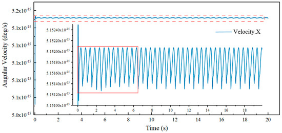
Figure 8.
Variation curve of angular velocity in the x-axis direction of orbiting scroll.
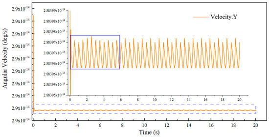
Figure 9.
Variation curve of angular velocity in the y-axis direction of orbiting scroll.
3.3. Analysis of the Orbiting Scroll Motion State
In order to explore the motion law of the orbiting scroll more accurately, the velocity change data of the orbiting scroll in the x-axis and y-axis directions measured by Adams were extracted and analyzed by Matlab fitting. The fitting formula of Vx is:
The fitting formula of Vy is:
Table 1 shows the fitting values at different rotation angles, where c is equal to the sum of the initial position phase angle and the rotation phase angle of the orbiting scroll. The velocity-fitting equations all have extremely small phase rotation angles. There is a certain gap between the key and the keyway, resulting in the orbiting scroll rotating slightly while performing the translational motion, which also reveals that the orbiting scroll has periodic angular velocity changes in the x- and y-axis directions.

Table 1.
Fitting values under different rotation angles.
4. Kinematics Analysis of Oldham’s Coupling
4.1. Motion Simulation Analysis of Oldham’s Coupling
Oldham’s coupling and the orbiting scroll are the main moving parts of the scroll compressor. To better analyze the kinematic characteristics of the orbiting scroll, it is necessary to study the motion law of Oldham’s coupling. Figure 10 shows the change curve of the speed component of Oldham’s coupling in the x- and y-directions. It can be seen from Figure 10 that the speed change amplitude of Oldham’s coupling in the y-direction is twice the speed change amplitude in the x-direction, which is also the reason the rotational angular velocity of the orbiting scroll in the x-direction is an order of magnitude smaller than the rotational angular velocity in the y-direction.
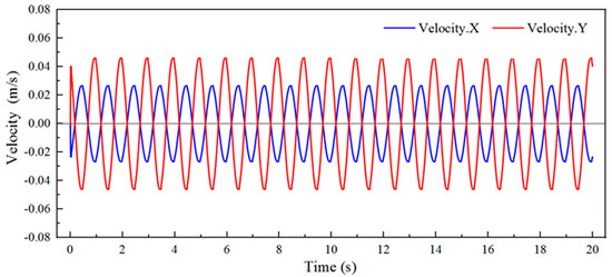
Figure 10.
Velocity component curve of Oldham’s coupling.
Figure 11 shows the time-varying curves of the centroid position, velocity, and acceleration of Oldham’s coupling. The motion of the centroid of Oldham’s coupling and the orbiting scroll is both a simple harmonic motion. During the dynamic analysis, the displacement trajectory of Oldham’s coupling and the displacement trajectory of the orbiting scroll will be superimposed. It can be seen from the comparison between Figure 6 and Figure 11 that in the same period, the moving frequency of Oldham’s coupling is approximately twice that of the orbiting scroll. In one period of the position change of Oldham’s coupling, the acceleration of its centroid reaches the peak twice, and the two peaks are generated when Oldham’s coupling is at the same limit position of the mainframe keyway. The changing trend of the centroid velocity of Oldham’s coupling is opposite to the acceleration, therefore when the centroid acceleration becomes smaller, the centroid velocity increases, and when the centroid acceleration is 0, the centroid velocity reaches the peak value. Because of the clearance fit between the convex key of Oldham’s coupling and the keyway of the orbiting scroll, when the scroll compressor is running, the clearance will cause the impact collision between the convex key and the keyway, which causes the centroid acceleration of Oldham’s coupling periodically to oscillate. The convex key of Oldham’s coupling extrudes different planes of the mainframe keyway in the first half period and the second half period, respectively, resulting in the angular velocity of the orbiting scroll producing a sudden change every half-cycle, so there is an extremely small initial phase angle in the velocity change equation of the orbiting scroll.
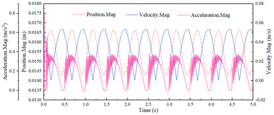
Figure 11.
Variation curves of position, velocity, and acceleration of Oldham’s coupling.
4.2. Optimization Analysis of Oldham’s Coupling
The moving pair formed by the combination of the convex key of Oldham’s coupling and the keyway of the mainframe and orbiting scroll is low. As shown in Figure 12, due to the clearance fit between the keyway and the convex key of Oldham’s coupling, there must be an impact during the contact process. During the start-up stage of the scroll compressor, the orbiting scroll will show a sudden acceleration. At this time, the convex key of Oldham’s coupling and the keyway of the orbiting scroll will have a great impact, which will easily lead to damage to the orbiting scroll. Therefore, it is necessary to optimize the structure of Oldham’s coupling. As shown in Figure 13, the convex key of Oldham’s coupling was optimized to a cylindrical structure, the form of the contact pair was changed from a low pair to a high pair, and the optimized scroll compressor model was analyzed based on the control variable method, compared with the simulation results before optimization.
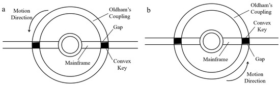
Figure 12.
Convex key extrusion mainframe keyway. (a) The convex key of Oldham’s coupling impacts the lower surface of the keyway of the frame (b) The convex key of Oldham’s coupling impacts the upper surface of the keyway of the frame.
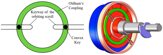
Figure 13.
Kinematic model after structure optimization.
The orbiting scroll and the fixed scroll are the core of the scroll compressor, so the motion state of the orbiting scroll is used as the evaluation criterion. Figure 14 shows the velocity and acceleration of the orbiting scroll in the x-direction of the prototype model after structural optimization. Compared with Figure 7, the component velocity of the orbiting scroll in the x-axis direction has not changed, indicating that the improved Oldham’s coupling can ensure the operation reliability of the scroll compressor. When the scroll compressor starts, the acceleration component of the orbiting scroll in the x-direction is significantly reduced, from 0.07 m/s2 before the improvement to 0.03 m/s2 after the improvement, a decrease of 53%.
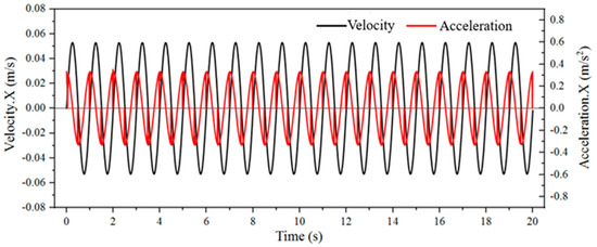
Figure 14.
The velocity and acceleration components of the improved scroll in the x-direction.
The magnitude of the rotation amplitude of the orbiting scroll has a very important influence on the reliable operation of the scroll compressor. To further explore the influence of the improved model on the rotation of the orbiting scroll, the impact of the orbiting scroll in the stable stage after 6 s is analyzed, compared with the average values of angular velocities in the x- and y-directions. As shown in Figure 15, we define the prototype model before improvement as Group 1 and the improved prototype model as Group 2. In the stable operation stage of the scroll compressor, the average value of the angular velocity in the x-direction is significantly smaller than that of Group 1, approximately 50% lower, while the average angular velocity in the y-direction does not change significantly, which indicates that the contact state between the Oldham’s coupling convex key and the keyway of the orbiting scroll greatly affects the angular velocity of the orbiting scroll in the x-axis direction. Optimized Oldham’s coupling can significantly reduce the contact impact with the orbiting scroll. When the scroll compressor runs at high speed, it can effectively improve the working reliability of the orbiting scroll.
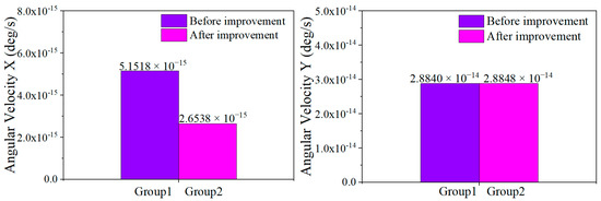
Figure 15.
Average angular velocity of the orbiting scroll in the x- and y-directions in the stable phase after 6 s.
5. Conclusions
In order to explore the influence of the moving pair’s contact form on the kinematic characteristics of the scroll compressor, the motion characteristics of the orbiting scroll and Oldham’s coupling were analyzed, and the reasons for the impact between Oldham’s coupling and the orbiting scroll were revealed. The result shows:
- (1)
- During the operation of the scroll compressor, the moving frequency of Oldham’s coupling is approximately twice that of the orbiting scroll in the same period, and the acceleration reaches its peak when Oldham’s coupling moves to the limit position of the mainframe keyway, so the impact of the convex keys of Oldham’s coupling on the mainframe keyway is more severe than that of the orbiting scroll keyway. In the maintenance of the scroll compressor, special attention should be paid to the wear of the mainframe keyway.
- (2)
- Due to the existence of the motion pair clearance, the orbiting scroll will rotate slightly while performing the translational motion. When the crankshaft rotation angle reaches 0° and 180°, the acceleration of the orbiting scroll reaches the maximum value, the convex key of Oldham’s coupling is at the limit position of the keyway of the orbiting scroll, and the impact of the two causes a sudden change in the angular velocity of the orbiting scroll in the x- and y-axis directions, which also causes a significant fluctuation of the centroid velocity of the orbiting scroll every half cycle.
- (3)
- By optimizing the structure of the convex key of Oldham’s coupling and improving the contact form between Oldham’s coupling and the orbiting scroll, the rotation angle velocity amplitude of the orbiting scroll in the stable operation stage can be greatly reduced, and the acceleration mutation phenomenon in the start-up stage of the orbiting scroll can be effectively alleviated, which causes the scroll compressor to run more stably and improve its work efficiency, bringing more economic benefits to the industrial field where the scroll machinery is widely used. In the future, the impact vibration between the convex key of Oldham’s coupling and the keyway can be further analyzed through experiments, and the optimization method of the scroll compressor with a better vibration reduction effect can be sought.
Author Contributions
Conceptualization, Y.Z. and W.Y.; methodology, Q.G.; software, L.Z.; validation, W.W. and S.Z. All authors have read and agreed to the published version of the manuscript.
Funding
This research was funded by National Natural Science Foundation of China (No. 52075306), the China Postdoctoral Science Foundation (2022M712393), the Key R&D project of Shandong Province (2019GGX104081, 2019GGX104033), Shandong Province’s Key Support Regions Introducing Urgently Needed Talent Projects, and the Young Innovative Talents Introduction and Training Program Project of Shandong Provincial Department of Education.
Institutional Review Board Statement
Not applicable.
Informed Consent Statement
Not applicable.
Data Availability Statement
Not applicable.
Conflicts of Interest
The authors declare no conflict of interest.
References
- Zheng, S.; Wei, M.; Hu, C.; Song, P.; Tian, R.; Li, Y.; Sun, J.; Wu, D. Impact of micro-grooves in scroll wrap tips on the performance of a trans-critical CO2 scroll compressor. Int. J. Refrig. 2021, 131, 493–504. [Google Scholar] [CrossRef]
- Shen, Y.; Liu, D.; Liu, L.; Li, S.; Chen, S.; Gan, Z.; Qiu, M. Experimental study on a floating scroll-type compressor driving a precooled JT cryocooler. Appl. Therm. Eng. 2020, 178, 115627. [Google Scholar] [CrossRef]
- Zhang, Q.; Feng, J.; Zhang, Q.; Peng, X. Performance prediction and evaluation of the scroll-type hydrogen pump for FCVs based on CFD–Taguchi method. Int. J. Hydrogen Energy 2019, 44, 15333–15343. [Google Scholar] [CrossRef]
- Ivlev, V.I.; Misyurin, S.Y. Calculated and experimental characteristics of a scroll machine operating in the air motor mode. Dokl. Phys. 2017, 62, 42–45. [Google Scholar] [CrossRef]
- Wang, C.; Wu, J.; Cheng, J.; Zhang, S.; Zhang, K. Elasto-hydrodynamic lubrication of the journal bearing system with a relief groove in the scroll compressor: Simulation and experiment. Tribol. Int. 2022, 165, 107252. [Google Scholar] [CrossRef]
- Qiang, J.; Liu, Z. A compression process model with integral equations for the scroll mechanism in a scroll compressor. Int. J. Refrig. 2014, 44, 101–115. [Google Scholar] [CrossRef]
- Kutlu, C.; Erdinc, M.T.; Li, J.; Su, Y.; Pei, G.; Gao, G.; Riffat, S. Evaluate the validity of the empirical correlations of clearance and friction coefficients to improve a scroll expander semi-empirical model. Energy 2020, 202, 117723. [Google Scholar] [CrossRef]
- Simon, E.; Tian, G.; John, C. A review of scroll expander geometries and their performance. Appl. Therm. Eng. 2018, 141, 1020–1034. [Google Scholar]
- Munoz, S.; Aceituno, J.; Urda, P.; Escalona, J. Multibody model of railway vehicles with weakly coupled vertical and lateral dynamics. Mech. Syst. Signal Process. 2019, 115, 570–592. [Google Scholar] [CrossRef]
- Zheng, W. Interactive virtual prototyping of a mechanical system considering the environment effect. Part 2: Simulation quality. Comptes Rendus Mec. 2011, 339, 605–615. [Google Scholar]
- Qiang, J.; Peng, B.; Liu, Z. Dynamic model for the orbiting scroll based on the pressures in scroll chambers—Part II: Investigations on scroll compressors and model validation. Int. J. Refrig. 2013, 36, 1850–1865. [Google Scholar] [CrossRef]
- Feng, J.; Zhang, Q.; Hou, T.A.; Peng, X. Dynamics characteristics analysis of the oil-free scroll hydrogen recirculating pump based on multibody dynamics simulation. Int. J. Hydrogen Energy 2021, 46, 5699–5713. [Google Scholar]
- Kim, K.; Hong, G.; Jang, G. Dynamic analysis of a flexible shaft in a scroll compressor considering solid contact and oil film pressure in journal bearings. Int. J. Refrig. 2021, 127, 165–173. [Google Scholar] [CrossRef]
- Hiwata, A.; Sawai, K.; Sakuda, A.; Morimoto, T.; Fukuta, M. A Study on Contact Force Between Wraps of Scroll Compressor for CO2 Refrigerant. Trans. Jpn. Soc. Refrig. Air Cond. Eng. 2010, 27, 75–86. [Google Scholar]
- Sungyong, A.; Seheon, C.; Chul, R.Y. Analysis of journal bearings in a scroll compressor considering deflections and dynamics of the crankshaft. Int. J. Refrig. 2018, 93, 205–212. [Google Scholar]
- Ahn, S.; Choi, S.; Lee, B.; Rhim, Y.C. Analysis of thrust bearing in high-side shell type scroll compressor. Int. J. Refrig. 2016, 69, 251–260. [Google Scholar] [CrossRef]
- Kim, M.; Shim, J.; Kim, J.; Jang, D.; Park, S. Multiphysics simulation and experiment of a thrust bearing in scroll compressors. Tribol. Int. 2020, 142, 105969. [Google Scholar] [CrossRef]
- Kim, J.; Lee, S.R.; Park, S.S. Analyses of thrust bearings in scroll compressors considering keyways. Tribol. Int. 2009, 43, 728–736. [Google Scholar] [CrossRef]
- Jianhua, W.; Jiachen, L. Effect of part deformation on performance of a rotary compressor using propane under high temperature. Appl. Therm. Eng. 2021, 194, 117145. [Google Scholar]
- Medrea, C.; Sideris, J.; Chicinas, I.; Ventouris, S. Analysis of fracture and cracks of oldham’s couplings used in anchor hoisting. Case study. Eng. Fail. Anal. 2013, 35, 590–596. [Google Scholar] [CrossRef]
- Bell, I.H.; Ziviani, D.; Lemort, V.; Bradshaw, C.; Mathison, M.; Horton, T.; Braun, J.; Groll, E. PDSim: A general quasi-steady modeling approach for positive displacement compressors and expanders. Int. J. Refrig. 2020, 110, 310–322. [Google Scholar] [CrossRef]
- Ziviani, D.; Bell, I.H.; Zhang, X.; Lemort, V.; De Paepe, M.; Braun, J.E.; Groll, E.A. PDSim: Demonstrating the capabilities of an open-source simulation framework for positive displacement compressors and expanders. Int. J. Refrig. 2020, 110, 323–339. [Google Scholar] [CrossRef]
- Machekposhti, D.F.; Tolou, N.; Herder, J.L. A statically balanced fully compliant power transmission mechanism between parallel rotational axes. Mech. Mach. Theory Dyn. Mach. Syst. Gears Power Trandmissions Robot. Manip. Syst. Comput. Aided Des. Methods 2018, 119, 51–60. [Google Scholar] [CrossRef]
- Deijl, H.; Klerk, D.D.; Herder, J.L.; Machekposhti, D. Dynamics of a compliant transmission mechanism between parallel rotational axes. Mech. Mach. Theory 2019, 139, 251–269. [Google Scholar] [CrossRef]
Publisher’s Note: MDPI stays neutral with regard to jurisdictional claims in published maps and institutional affiliations. |
© 2022 by the authors. Licensee MDPI, Basel, Switzerland. This article is an open access article distributed under the terms and conditions of the Creative Commons Attribution (CC BY) license (https://creativecommons.org/licenses/by/4.0/).