1. Introduction
A high-speed permanent magnet (PM) motor has been used extensively in flywheel energy storage, electric vehicles, high-speed rail, and other applications because of its advantages such as high power density, small size, light weight, and high efficiency. For high-speed electrical systems, various configurations are recommended. Specifically, a permanent magnet synchronous motor (PMSM), which is a PM-based motor, uses PMs on the rotor and conventional windings on the stator. In this case, the rotor spins synchronously with the rotating magnetic field of the stator. However, due to the high speed, the large carrier frequency of the PM, and the harmonics of the air-gap field, the eddy current loss in the PM increases. Additionally, due to limited internal space and insufficient heat dissipation conditions, the temperature of the rotor increases, and irreversible demagnetization of the PM may occur in severe cases, which reduces the reliability and safety of the motor. Therefore, accurate calculation of the rotor eddy current loss is crucial for the design and stable operation of a high-speed PM motor.
Several studies have been conducted to calculate the rotor eddy current loss of the PM motors [
1,
2,
3,
4,
5,
6,
7]. For the axial flux permanent magnet motor, the 2D analytical model cannot accurately calculate the eddy current loss of permanent magnets. To solve this problem, Tong et al. [
1] designed a 3D analytical model that can exactly calculate the eddy current loss of permanent magnets. The model uses the accurate subdomain method and the resistance network model and considers the effects of stator slotting and harmonic current on the calculation results. Han et al. [
2] used the 3D FEM to calculate the eddy current loss of a high-speed permanent magnet motor rotor under different sheath materials and structures. By comparing the data, the influence of this factor on rotor eddy current loss is summarized. Finally, the accuracy of the results is verified by experiments. Although the 3D FEM has very high accuracy, in the early stage of motor design, the three-dimensional finite element method was not only very cumbersome in modeling but also very slow in terms of calculation. In order to improve the calculation efficiency and optimize the motor scheme, Jung et al. proposed a 2D FEM to calculate the eddy current loss of rotor. After verification, it was found that this method can significantly improve the efficiency of motor design optimization. Du et al. [
4] developed a multi-parameter improvement method for high-speed motor design. In part of the winding design, after a large amount of data analysis, the relationship between the two parameters and eddy current loss is summarized. Based on the principle of magnetic field modulation, Su et al. [
5] calculated the harmonic components of permanent magnet magnetic field and armature reaction field, respectively, by taking the rotor permanent magnet flux-switching motor and the stator permanent magnet flux-switching motor as the research objects. The generation principle of the eddy current loss of permanent magnets of two kinds of motors is thoroughly studied. In order to reduce the rotor eddy current loss without affecting the motor output torque, Zhang et al. [
6] conducted an in-depth study of the auxiliary slotting of stator. The influence of the structure and the quantity of the auxiliary slots on the performance of the motor is summarized. Antomne et al. [
7] established a numerical model of the rotor of the high-speed permanent magnet motor by using the FEM and analyzed it by using the method based on the separation of the losses. The experimental results show that this method can accurately estimate different losses in the rotor in a short time. Additionally, the calculation method of rotor eddy current loss in a polar coordinate system was proposed by Zhu et al. [
8,
9]; the method includes five parts: a motor stator, a rotor sleeve, an air gap, a PM, and a rotor yoke. This model considers the time and space harmonics of current but does not calculate the end effect and the error caused by stator slotting. Moreover, there is a need to determine the complex Bessel function. Kim et al. [
10] established an analytical model according to the size of the permanent magnet motor and proposed a formula that can predict rotor eddy current loss. Compared with the traditional method, the formula is simpler and faster.
The numerous cited works of literature reported different methods of calculating and reducing the eddy current loss of a PM. However, most of them did not consider the armature reaction, the end effect of eddy current, and the large error in the eddy current loss calculation.
In this study, a high-speed PM motor with a power of 120-kW, a rated speed of 24,000 rpm, and a peak speed of 30,000 rpm was investigated. Based on the principle of the equivalent current sheet, a 2D model of the motor in the rectangular coordinate system was established. Considering the armature reaction and end effect, as well as the influence of current harmonics generated by variable frequency power supply, the rotor eddy current loss of the motor was analyzed and deduced. The accuracy of the analytical calculation was verified by comparing the analytical results with the 2D FE results.
To study the influence of the sleeve material and the thickness on the rotor eddy current loss, based on the 2D FEM, the eddy current loss of the rotor was compared and analyzed based on that of different sleeve materials. Additionally, graphene, a new type of material, was studied, and the influence of sleeve composite structure on rotor eddy current loss was analyzed. The basic parameters of the motor are shown in
Table 1.
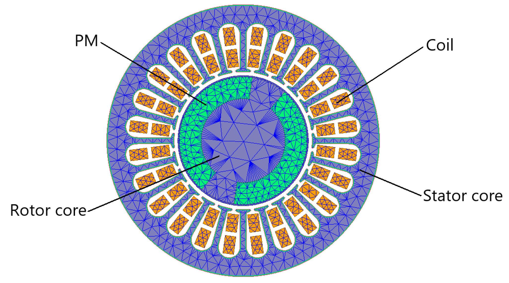
The model stator material is 20CS1500HF high-frequency silicon steel produced by China Steel Corporation. The silicon steel sheet is 0.2 mm thick, which can effectively reduce the iron loss of the stator. The winding is double-layer stacked winding. The sleeve is made of 1-mm-thick austenitic high-strength stainless steel, with a conductivity of 1,300,000 S/m. The permanent magnet adopts the permanent magnet NdFe35. The residual magnetic density of the permanent magnet is 1.23 T, and the coercivity is 890 kA/m. According to the above and the electrical parameters in
Table 1, the 2D FEM analysis model of the high-speed permanent magnet synchronous motor is shown in
Figure 1.
2. Analytical Calculation and Analysis of Rotor Eddy Current Loss
2.1. Analysis of Equivalent Current Sheet Model of Motor
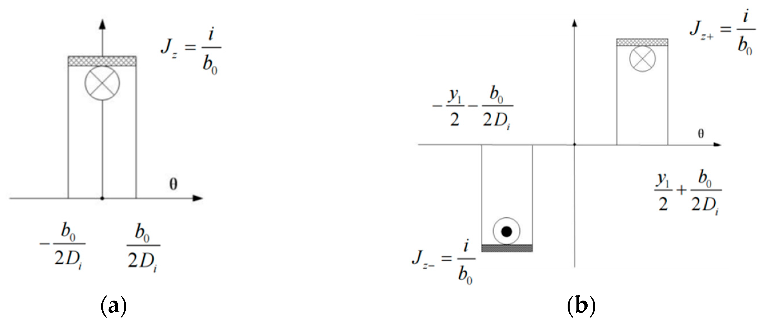
At present, the more accurate analytical calculation model of rotor eddy current loss is the rotor eddy current loss model of five layers of materials, including the stator core, the air gap, the protective sleeve, the permanent magnet, and the rotor yoke, established by Z.Q. Zhu in the polar coordinate system. The model considers the time and space harmonics of stator magnetic potential but does not consider the influence of end effect. Therefore, the rotor eddy current loss model of the high-speed permanent magnet synchronous motor is established in the rectangular coordinate system, and the effects of the eddy current armature reaction and the end effect are considered. Considering the influence of the stator winding current on the rotor but not the effect of the stator slot, the stator winding current can be equated to the equivalent current sheet distributed in the stator slot. Assuming that the current sheet is uniformly distributed in the slot, the equivalent distribution of a single conductor and a single coil in polar coordinates is shown in
Figure 2 [
8,
9,
11]:
According to
Figure 2a, the current sheet distribution function of a single conductor can be expressed as follows:
where
Di is the stator inner diameter (m),
i is the current in the conductor (A),
b0 is the slot width (m), and
θ is the angle (radian) along the circumferential direction with the stator as the coordinate system.
The following equation is obtained by the Fourier decomposition of (1):
where
v is the harmonic number.
If (2) is extended to a single coil as shown in
Figure 2b, the harmonic distribution function of the current sheet on both sides of a single coil can be obtained by taking their axes as the coordinate origin, which yields the following equations:
By adding (3) and (4) and extending them to phases A, B, and C, the harmonic distribution of the current sheet can be expressed as follows:
where
ksov is the notch coefficient,
kwv is the winding factor, and
kwv is the coefficient obtained by multiplying
kpv and
kdv.
The three-phase symmetrical positive sequence current in the three-phase winding of the motor is set as follows:
where
k is the current time harmonic number,
Ik is the time harmonic amplitude of
k-th current,
p is the motor pair of poles, and
t is time.
For this model, the total number of series turns per phase is
N, and the total synthetic equivalent current slice distribution function of the three-phase winding is the sum of the harmonic distribution expressions of phases A, B, and C winding current slices.
Jkv represents the linear current density amplitude of the equivalent current slice, and the distribution function of the total synthetic equivalent current slice of the three-phase winding can be simplified as:
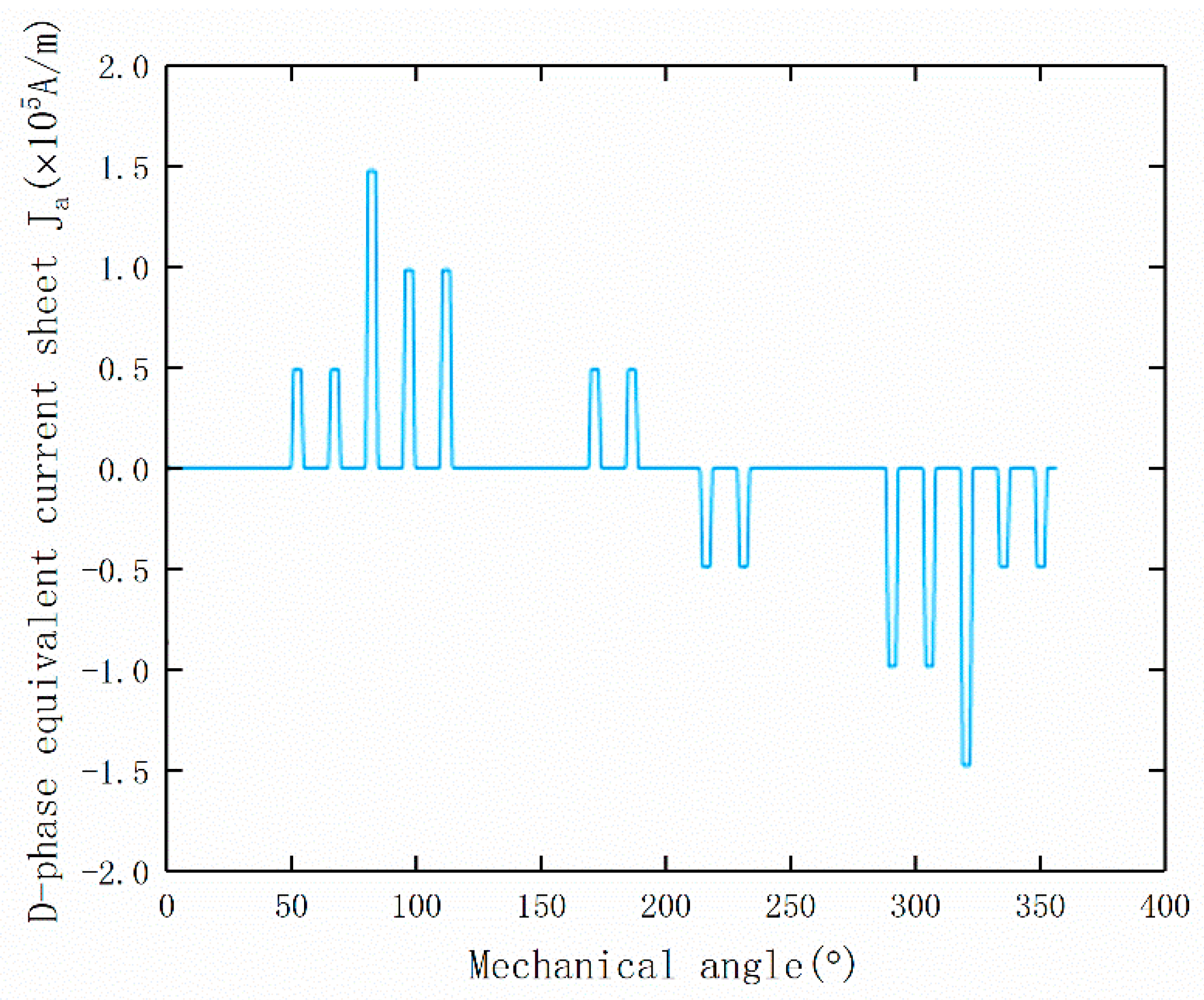
Using (7), the distribution of phases A, B, and C and three-phase synthetic equivalent current sheet of three-phase under no-load condition when
t = 0 can be obtained. The composite equivalent is shown in
Figure 3.
2.2. Establishment of Analytical Model of Rotor Eddy Current Loss
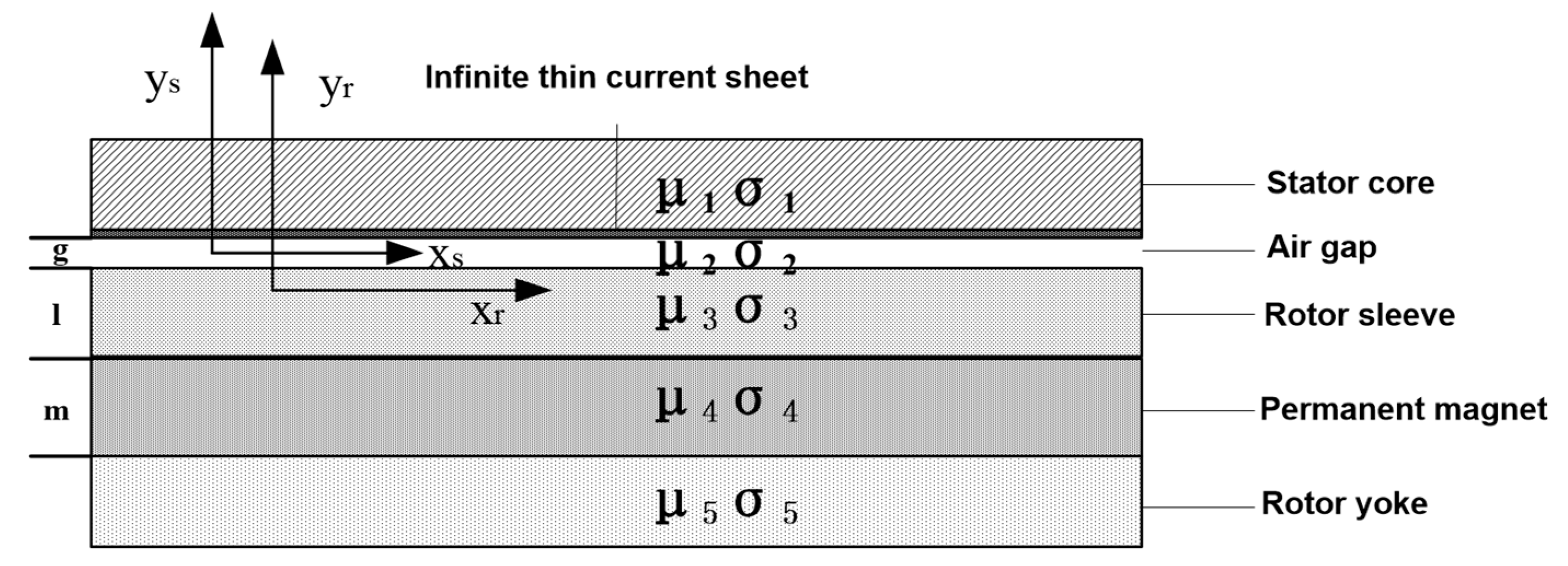
In the working frequency range of the motor, compared with the conduction current, the displacement current can be ignored, so the electromagnetic field of the motor is actually a quasi-stable alternating electromagnetic field. If the cylindrical coordinate system is adopted, the complex Bessel function needs to be solved, which is very complex. Due to the small thickness of the permanent magnet and the small penetration depth of the rotor yoke, the rectangular coordinate system will not produce large errors, and the analysis is convenient. In order to essentially analyze the mechanism of the rotor eddy current loss, the two-dimensional model of the permanent magnet synchronous motor in a stator rectangular coordinate system is adopted, as shown in
Figure 4. To simplify the calculation, the following assumptions were made [
11,
12,
13,
14]:
The stator winding current is replaced by an equivalent current sheet distributed sinusoidally in the slot of the stator.
The permeability of the stator core approaches infinity, and the conductivity tends to be infinitesimal.
The permeability and conductivity of the PM, sleeve, and rotor yoke are constant and isotropic.
The stator and rotor are planar ferromagnets.
The saturation effect and hysteresis effect of the core are ignored.
According to the electromagnetic field theory applied to the motor, the electromagnetic field equations of the air gap (8), the rotor sleeve (9), the PM motor (10), and the rotor yoke (11) are as follows, respectively:
where
,
,
, and
are the vector magnetic potential of the air gap, the rotor sleeve, the PM, and the rotor yoke, respectively.
ωr is the rotor speed, and
s is the slip rate of the
k-th current time harmonic and
v-th space harmonic. If the harmonic direction is the same as the rotor rotation direction, then
s = 1 −
v/
kp, and if it is the opposite, then
= s = 1 +
v/
kp (
p is the pair of poles).
2.3. General Solution of Air Gap Subdomain
The solution of the above equation can be obtained by the method of separating variables [
11]:
where
The above motor model satisfies the following boundary conditions:
of the rotor surface is continuous; thus,
The normal component of the interface flux density is continuous; thus,
If there is a surface current on the interface, the tangential component of the magnetic field strength is the interface current. Otherwise, the tangential component of magnetic field intensity is continuous; thus,
It can inferred from the above boundary conditions that
where
2.4. Analytical Calculation of the Rotor Eddy Current Loss
According to Poynting’s principle, the average electromagnetic power of the electromagnetic field entering the sleeve
P3 is as follows:
The average electromagnetic power entering the PM
P4 is expressed as follows:
The average electromagnetic power entering the rotor yoke
P5 is expressed as follows:
As the assumption of the model was based on the infinite length of the axial core of the motor, the end effect of the eddy current was not considered. Therefore, the circumferential eddy current effect was excluded. In this study, the end effect treatment method of the induction motor [
11,
12,
13,
14,
15] was used to consider the end effect in the PM motor. Hence, the total rotor eddy current loss
PZ after treatment can be expressed by the following equation:
where
is the end coefficient and
is the axial length of the core.
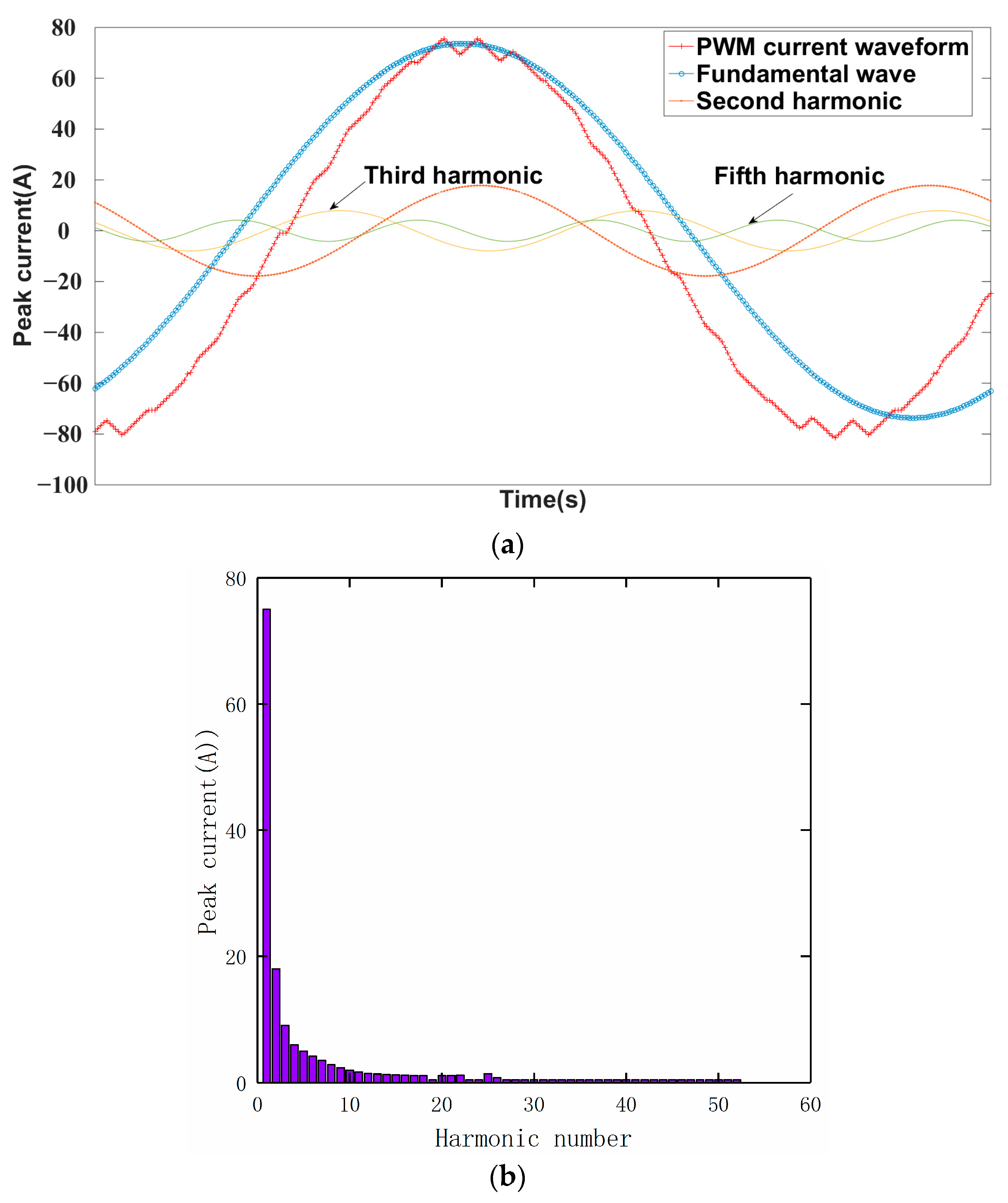
The rotor eddy current loss is mainly affected by the stator slot, the space harmonics caused by stator winding magnetomotive force, and the time harmonics of the stator winding current generated by inverter. Through the joint simulation of Simplorer and Maxwell, the PWM current waveform of one cycle under the motor load and rated speed were analyzed. The waveform and amplitude Ik of each current time harmonic were obtained, and the rotor eddy current loss caused by the
k-th current time harmonics and v-order space harmonics were obtained by introducing it into the above formula. The harmonic decomposition waveform and harmonic analysis diagram of the PWM current are shown in
Figure 5.
After performing the calculation, it can be inferred that the rotor eddy current loss changes with the frequency. In this study, the variation of the rotor eddy current loss with the frequency of a 120-kW high-speed PM motor under the load was calculated using MATLAB, as shown in
Figure 6. In the case of analytical calculation, the rotor eddy current loss will increase significantly with the increase of frequency. When the frequency is 400 Hz, the eddy current loss is 249.02 W, and when the frequency is 1200 Hz, the rotor eddy current loss increases significantly to 434.99 W. The size of the rotor eddy current loss can be analyzed qualitatively and quantitatively by analytical calculation, which has certain engineering value.
3. FEM Analysis of Rotor Eddy Current Loss
The analytical method can easily and intuitively reflect the principle and theory regarding the rotor eddy current loss. The FE method can accurately calculate the rotor eddy current loss and can deal with complex boundary conditions. For the FE analysis of rotor eddy current loss, this study adopted the time stepping FEM. In this section, the time stepping FEM is used to quantitatively calculate and analyze the main factors affecting the rotor eddy current loss. Due to the influence of skin effect, the electromagnetic wave can only pass through a thin layer on the surface of the rotor yoke. In order to accurately calculate the eddy current loss, the grid division should be carefully considered in the FEM analysis of the eddy current field in the rotor area. The grid size of the sleeve and magnetic pole area should be less than the penetration depth of the magnetic field.
3.1. Harmonic Analysis of FEM Model
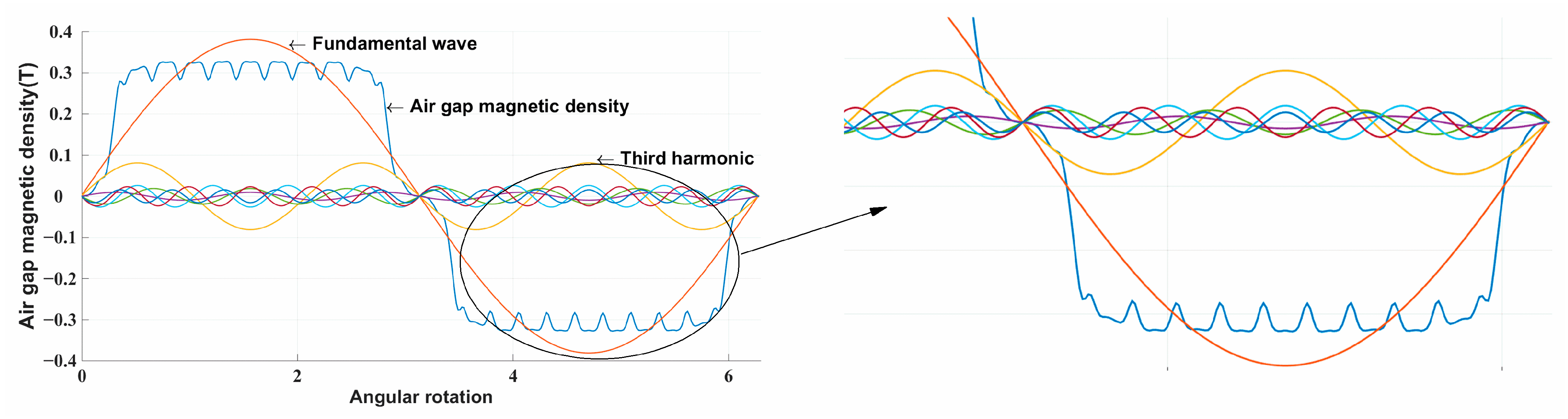
Space harmonics is one of the important factors that affects the eddy current loss of the rotor. A series of harmonic waveforms obtained by Fourier decomposition of magnetic density were analyzed by the FE method, as shown in
Figure 7.
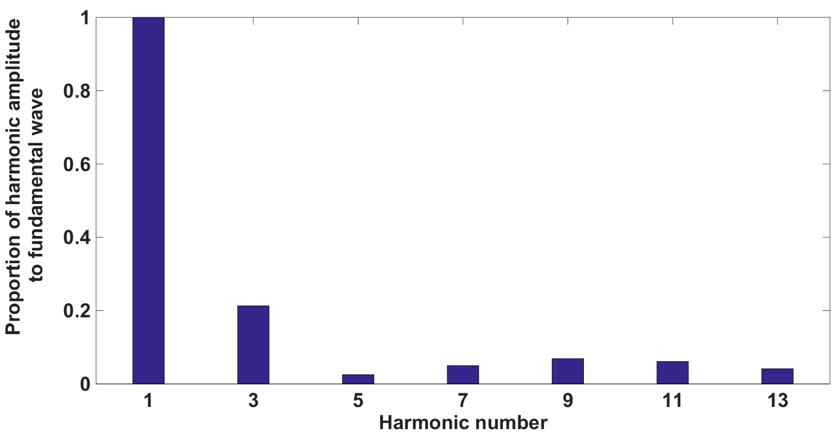
According to the harmonic amplitude of the Fourier decomposition, other harmonics except the fundamental wave can be obtained. In this study, the first 13 harmonics were selected for analysis, and the proportion of harmonics to the fundamental wave was obtained, as shown in
Figure 8.
It is apparent from
Figure 8 that the third harmonic accounts for the largest proportion, which is about 0.2; the proportion of the 9th and 11th harmonics is the second, which is 0.1; and the harmonics are mainly concentrated in the 3rd, 7th, 9th, and 11th harmonics, particularly the 3rd harmonic, accounts for 21% of the fundamental wave.
3.2. Analytical Calculation and FEM Analysis
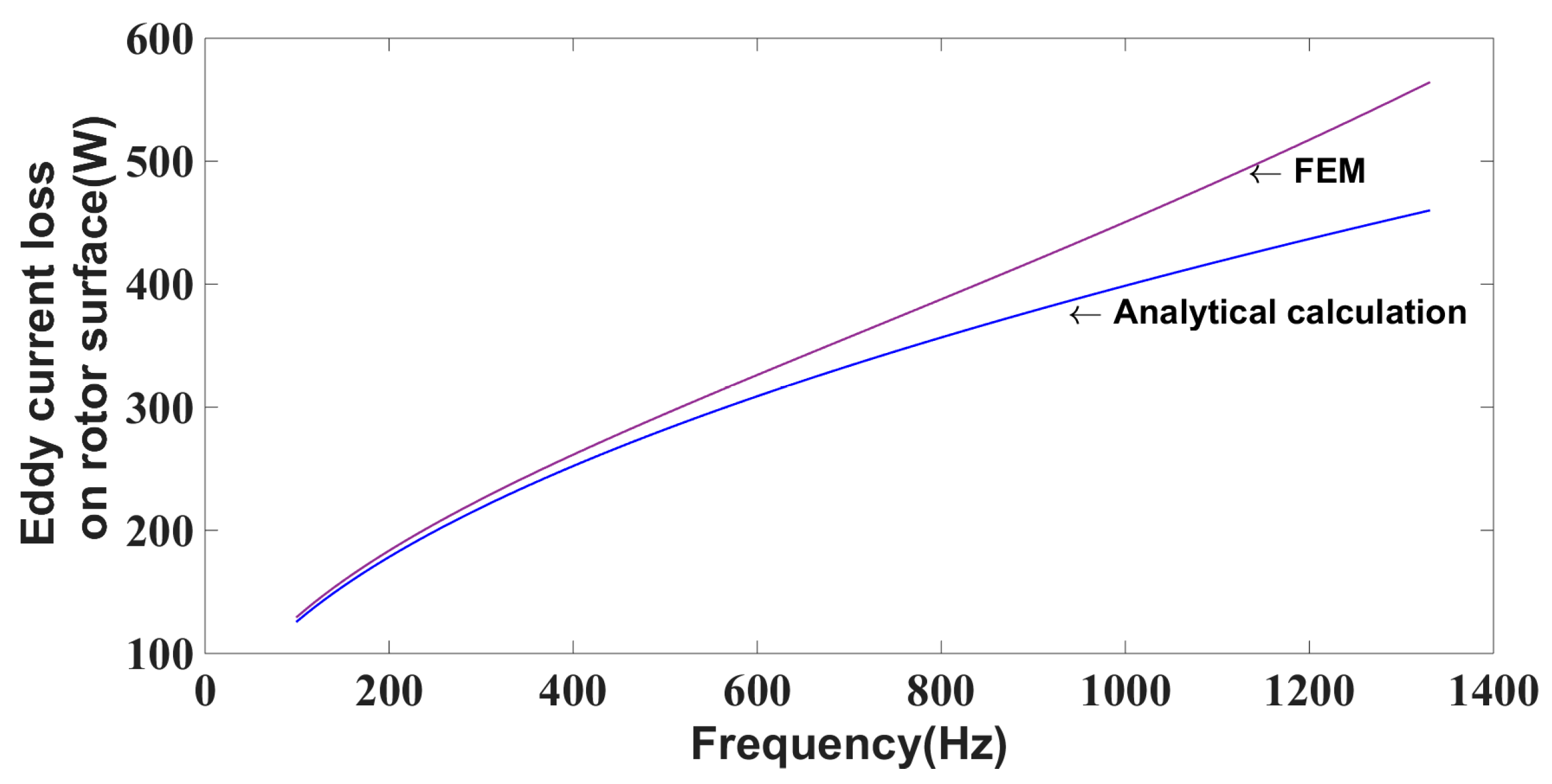
The influence of the variation of the motor frequency on the rotor eddy current loss was studied by time FEM analysis and the analytical method. When the rated frequency was 400 Hz, the rotor eddy current loss was analytically calculated to be 249.02 W, and the corresponding simulated value by FEM analysis was 257.96 W. The difference between these values was 3.6%, and the error was within a reasonable range. The comparison between the analytical calculation and FEM simulation results under load is shown in
Figure 9.
As can be seen from
Figure 9, when the stator current is constant, the rotor eddy current loss increases with the increase of frequency. At the same time, when the frequency exceeds 600 Hz, the results of rotor eddy current loss calculated by analytical calculation and FEM calculation are more and more different. In order to further compare the differences between the two algorithms, the eddy current loss results of the analytical calculation method and FEM analysis were compared at 200 Hz, 400 Hz, 600 Hz, 800 Hz, 1000 Hz, and 1200 Hz, as shown in
Table 2.
Table 2 shows the error from the range of 200–600 Hz, in which the variation trend of the rotor eddy current loss with frequency, as obtained by analytical calculation and FEM analysis, is still within the reasonable range. However, as the frequency continues to increase, the magnitude of the error continually increases. The error is 12.8% at 1000 Hz and 18.2% at 1200 Hz. The result of FEM simulation of the rotor eddy current loss is much higher than that of analytical calculation. Frequency is one of the important factors affecting the rotor eddy current loss of the permanent magnet motor. Analytical calculation and FEM calculation are two different methods to calculate eddy current loss. The relationship between the eddy current loss and the frequency,
f, is different in the two methods. The eddy current loss is proportional to
fn in the FEM and is proportional to
fm in the analytical calculation. The ‘
n’ in the FEM calculation is slightly larger than
m in the analytical calculation. In the case of low frequency, the difference between the two results is not big; with the increasing frequency, the error between the two will gradually increase.
4. Influence of Rotor Sleeve on Rotor Eddy Current Loss
For the high-speed permanent magnet synchronous motor with surface-mounted magnetic steel, in order to prevent the permanent magnet from falling off due to the centrifugal force generated by the high-speed rotation of the rotor, a high-strength non-magnetic protective sleeve is generally configured outside the permanent magnet. There are two kinds of commonly used protective sleeve materials: metal and non-metal. Metal materials, such as non-magnetic titanium alloy and stainless steel, have high conductivity. The harmonic magnetic field will produce large eddy current loss in the protective sleeve, but metal materials have high thermal conductivity, which is conducive to heat loss in the permanent magnet; for non-metallic materials, such as glass ribbon and carbon fiber, the conductivity is low and the loss in the protective sleeve is small, but their thermal conductivity is also low, which is not conducive to the heat dissipation of the rotor. The conductivity and thickness of the protective sleeve have a great influence on the rotor eddy current loss. The eddy current loss of the rotor will eventually be reflected in the form of heat. If the eddy current loss is too large, it will lead to the temperature rise of the PM, and irreversible demagnetization will occur when the temperature rise is serious. Therefore, it is necessary to analyze the influence of the protective sleeve on the rotor eddy current loss to reduce the rotor eddy current loss of high-speed permanent magnet synchronous motor.
Before eddy current loss analysis, a stress analysis was carried out on the rotor part, which met the safety standards. At the same time, when discussing the influence of the sleeve on rotor eddy current loss, it is necessary to ensure that the length of the air gap between the stator and rotor is fixed. On the premise that the thickness of the permanent magnet remains unchanged, the increased thickness of the sleeve is realized by reducing the outer diameter of the rotor core. In the process of motor design, this paper leaves a certain margin for the design of rotor size on the premise of ensuring the output performance of motor. Therefore, the influence of a slight change of rotor core size on eddy current loss is far less than that of the sleeve size.
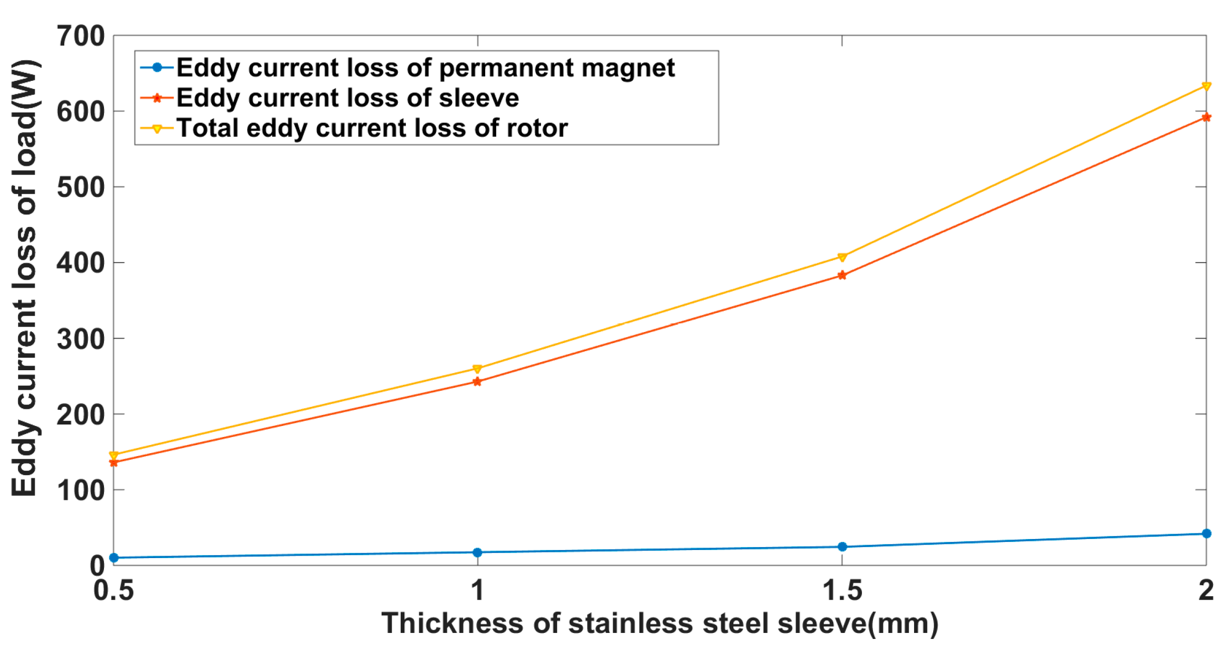
4.1. Influence of Sleeve Thickness on Eddy Current Loss of Rotor
According to the comparative analysis of Chapters 2 and 3, in order to ensure the calculation accuracy, the FEM simulation models of sleeves with thicknesses of 0.5 mm, 1.0 mm, 1.5 mm, and 2.0 mm are established in this paper. The material was set as austenitic stainless steel (conductivity: 1,300,000 S/m). The variation trend of the eddy current loss of the motor rotor with the sleeve thickness under a given load condition is shown in
Figure 10.
When the thickness of the sleeve was 0.5 mm, the eddy current loss of the sleeve and the PM were 136.08 W and 10.22 W, respectively. It can be seen from
Figure 10 that when the sleeve thickness increased, the total eddy current loss of the rotor also increased. The increase was significant when the sleeve thickness was 2 mm, reaching 633.8 W, which included 592 W of the sleeve eddy current loss and 41.8 W of PM the eddy current loss. It can be seen that when austenitic stainless steel with high conductivity is used, most of the total eddy current loss is concentrated on the sleeve. At the same time, with the increasing thickness of the sleeve, the eddy current loss of the permanent magnet changes little. However, the eddy current loss on the sleeve increases with the increasing thickness of the sleeve.
The increase in the sleeve thickness mainly increases the eddy current loss of the sleeve.
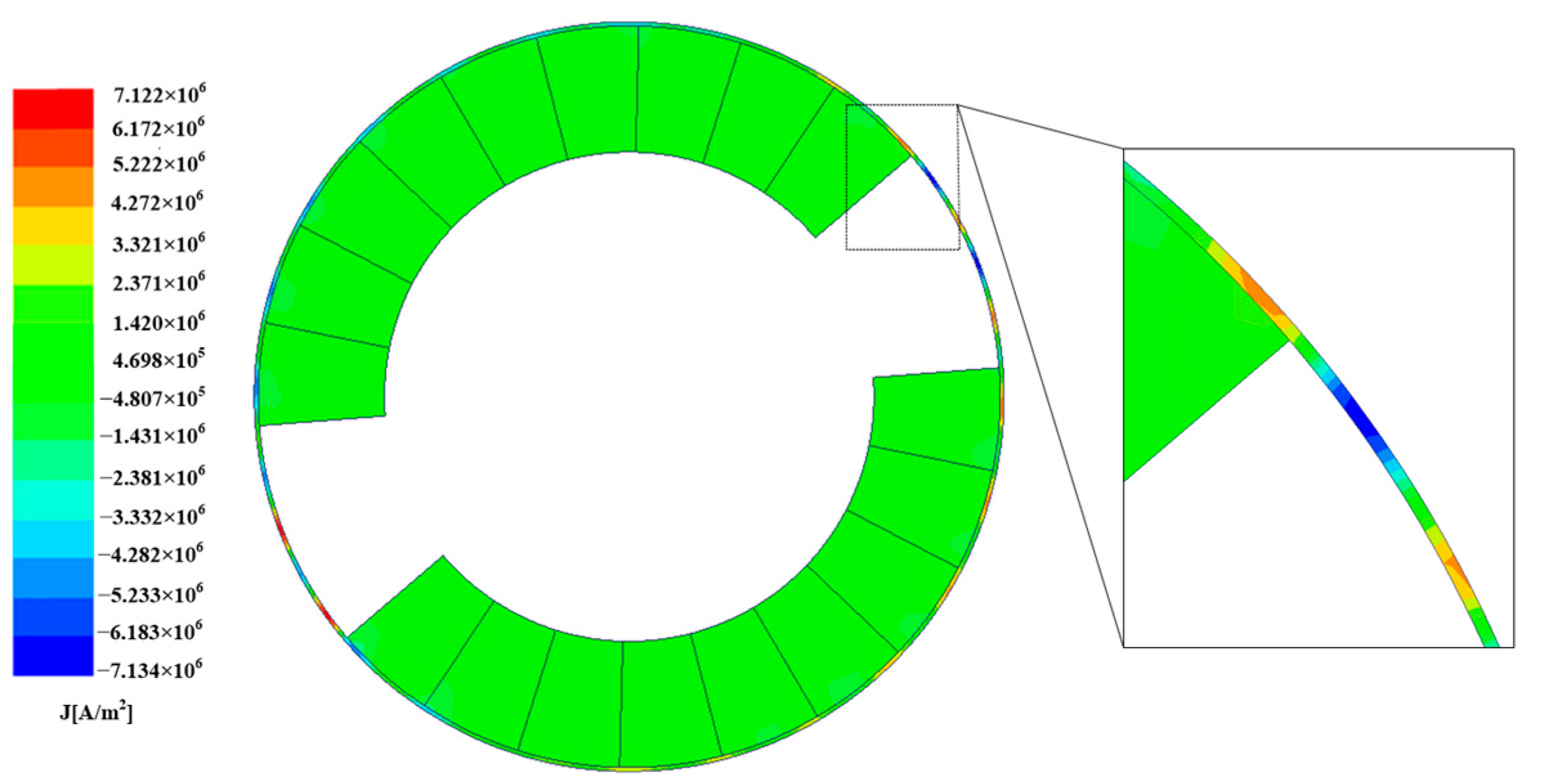
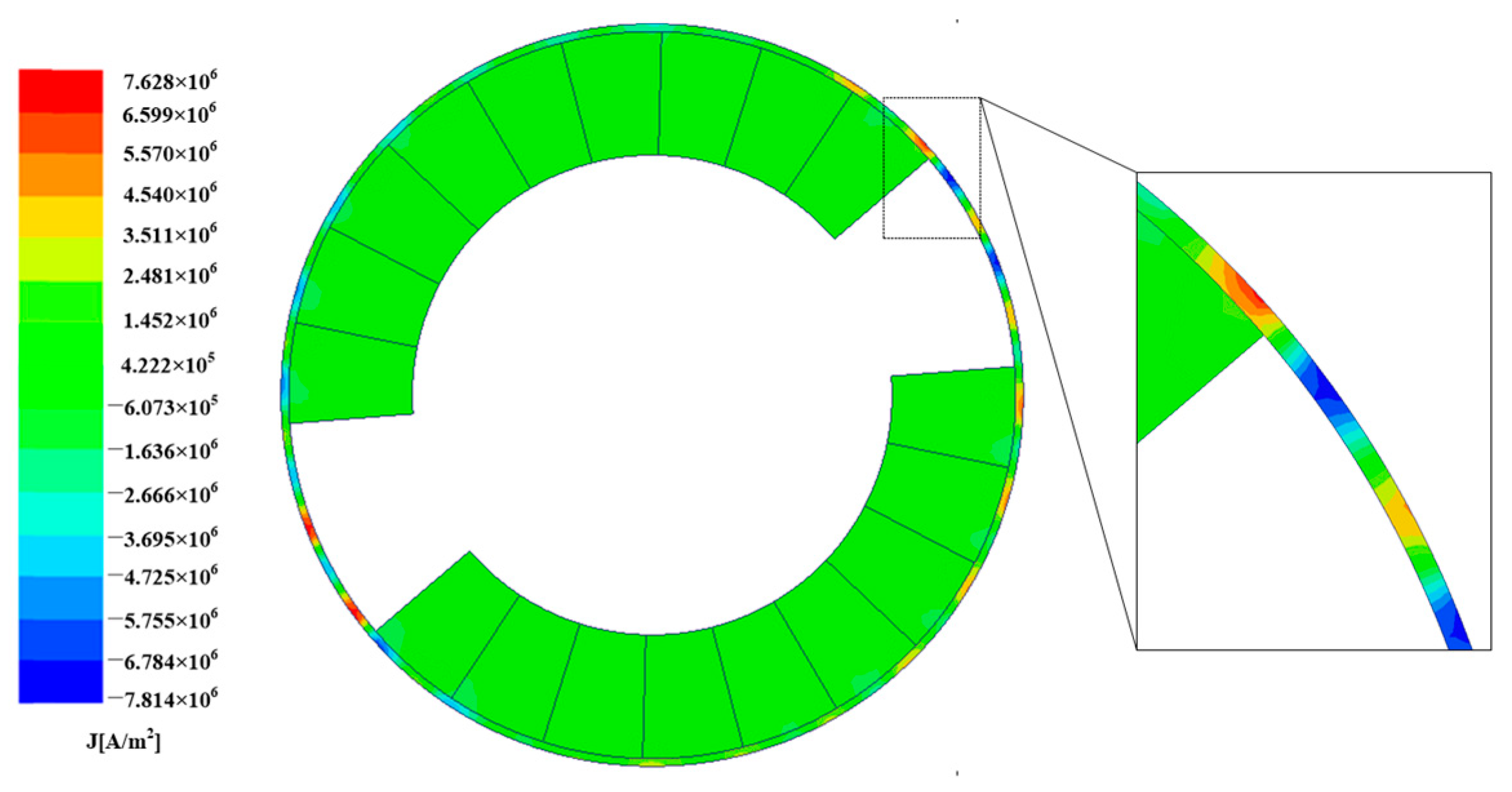
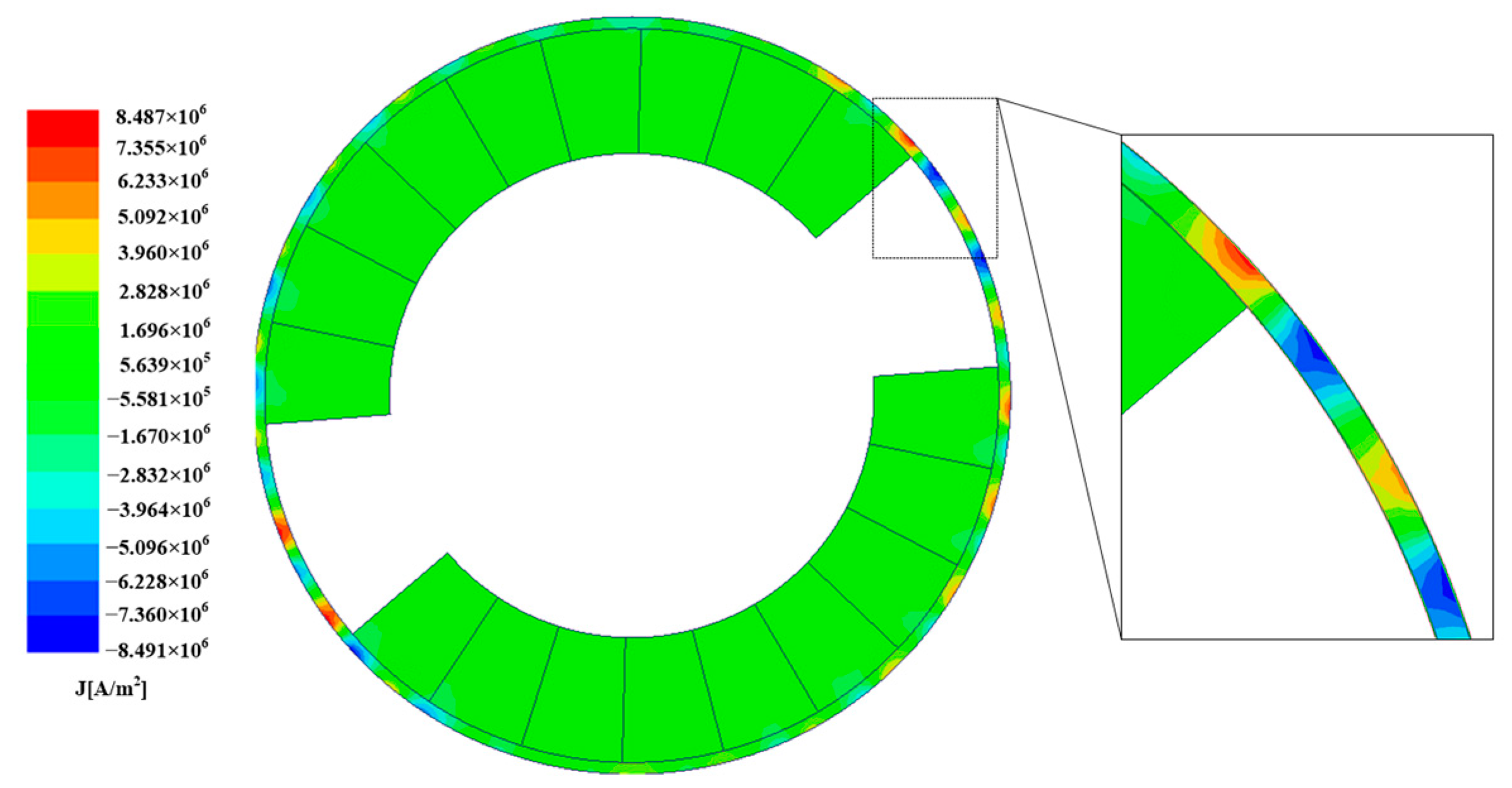
Figure 11,
Figure 12,
Figure 13 and
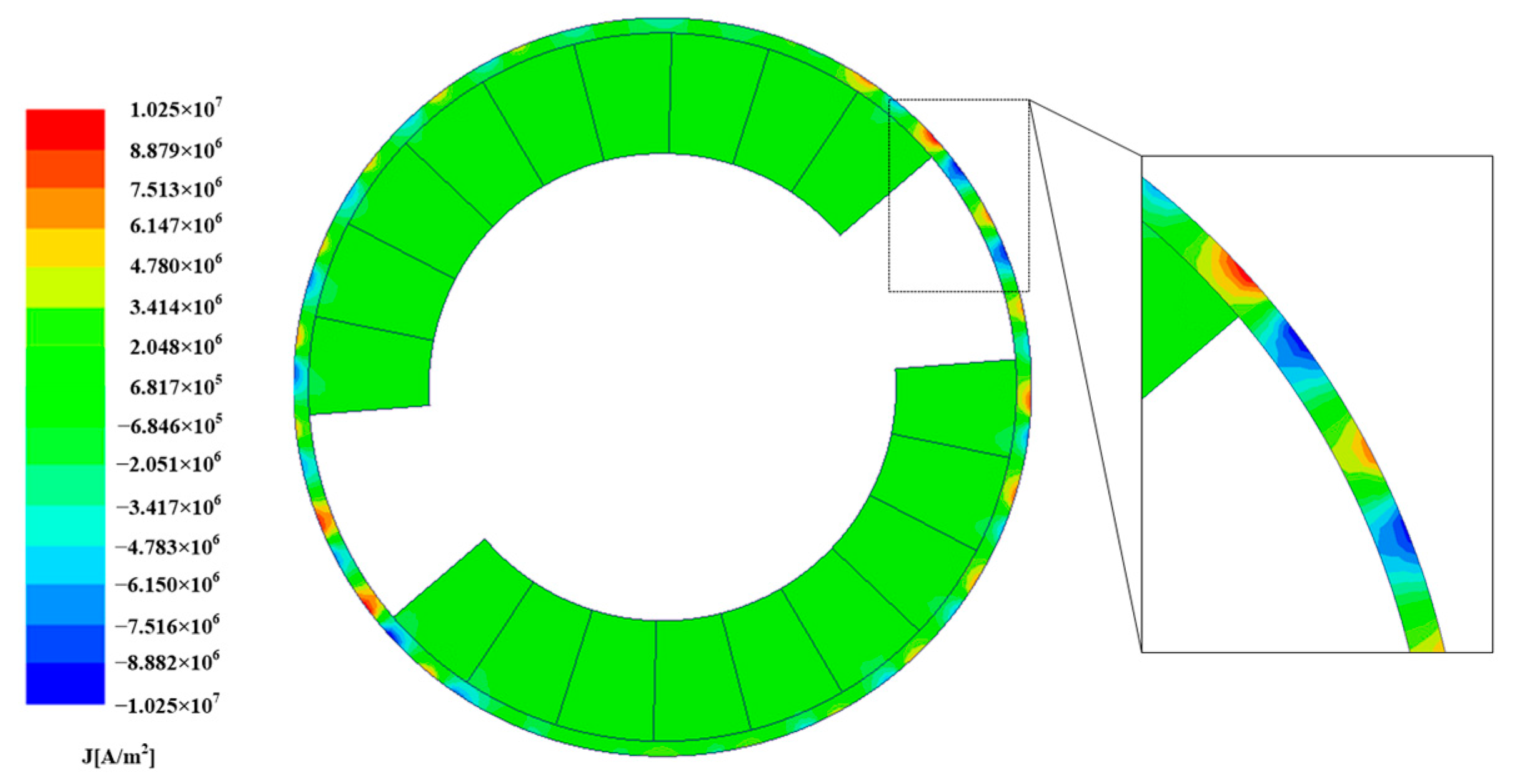
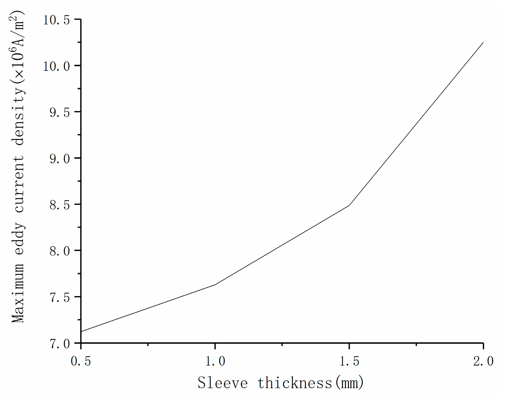
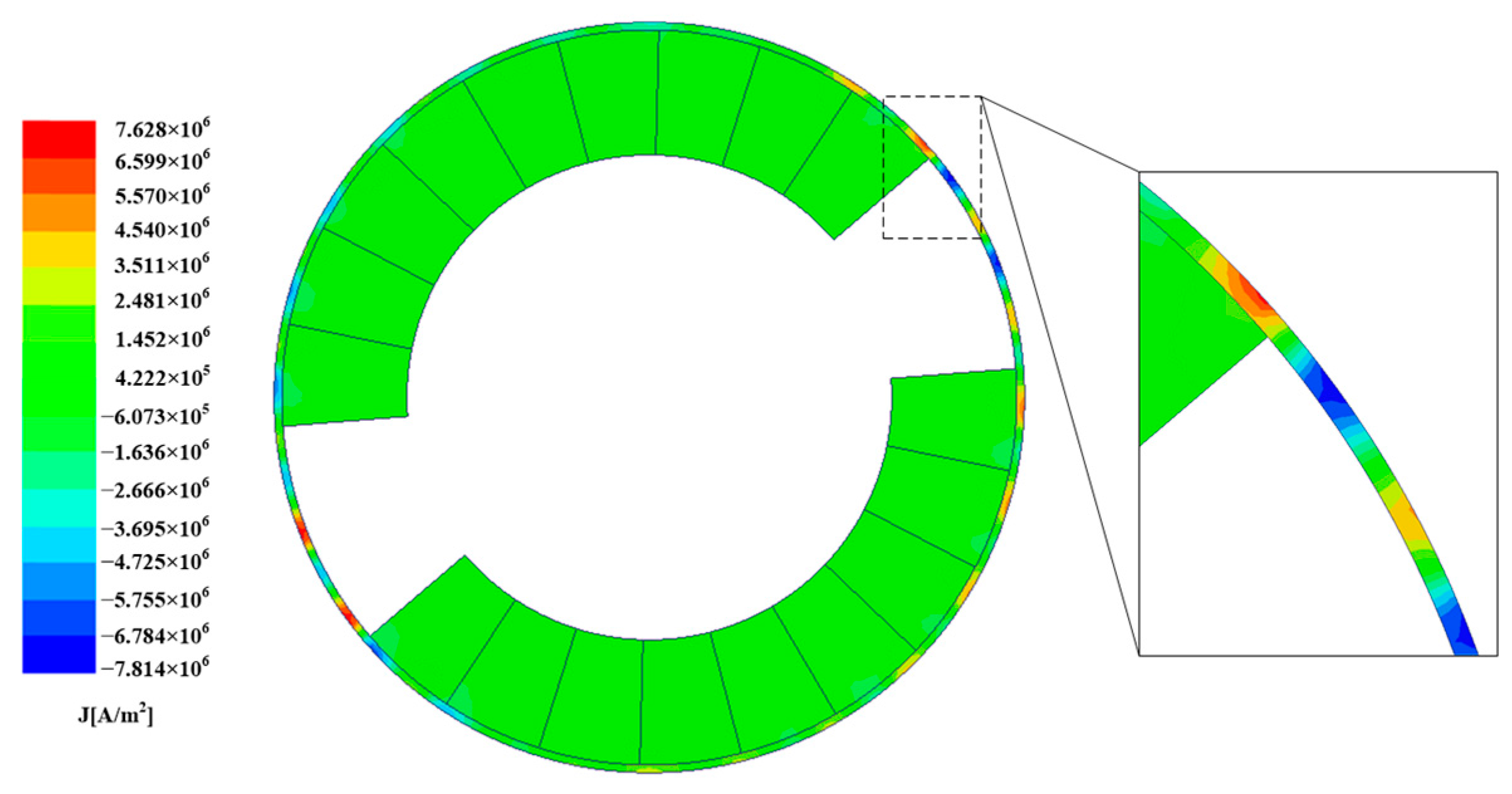
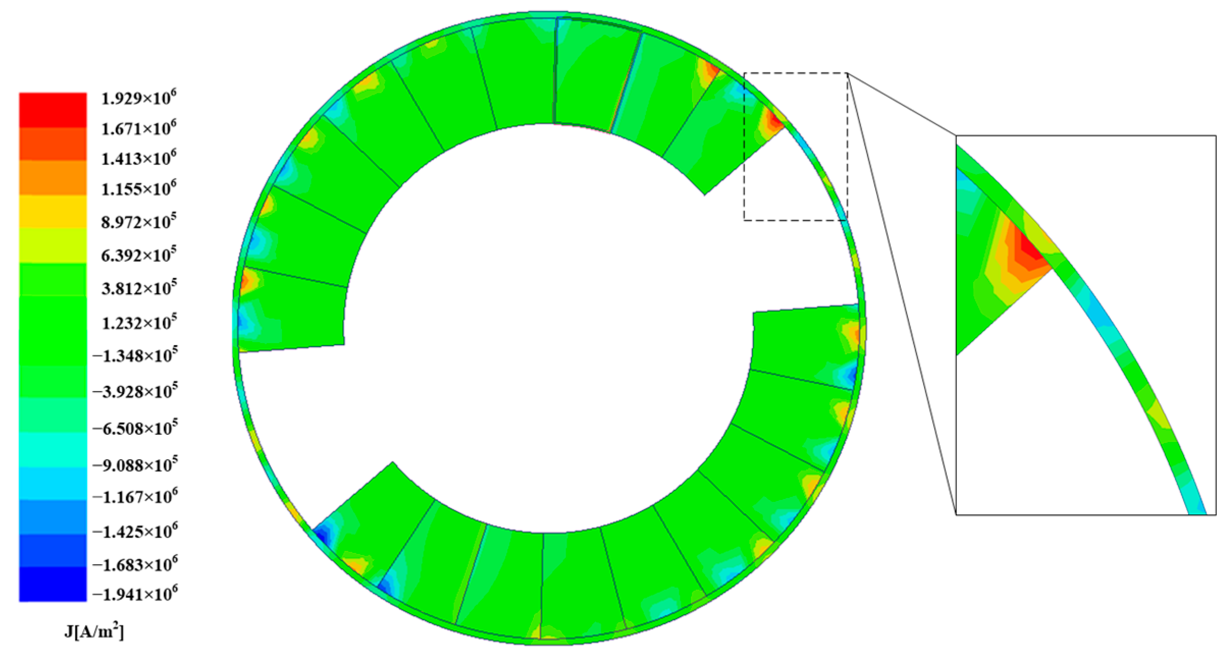
Figure 14 show the eddy current density distributions of the PM and the sleeve at 0.2 s for different sleeve thicknesses. The trend of the maximum eddy current density of the sleeves with different thicknesses is shown in
Figure 15.
In the case of the stainless-steel sleeve, the eddy current density is mainly concentrated in the sleeve part, and only a small amount of eddy current density is distributed in the PM. For the sleeve thicknesses of 0.5 mm, 1 mm, 1.5 mm, and 2 mm, the maximum eddy current densities are, respectively, 7.122 × 10⁶ A/m2, 7.628 × 10⁶ A/m2, 8.487 × 10⁶ A/m2, and 1.025 × 10⁷ A/m2. For the stainless-steel sleeve, the eddy current density is mainly concentrated on the sleeve, indicating that the sleeve has a certain shielding effect on the harmonic magnetic field of the air gap magnetic field. At the same time, the maximum eddy current density of the sleeve increases with the increase of sleeve thickness.
4.2. Influence of Sleeve Material on Eddy Current Loss of Rotor
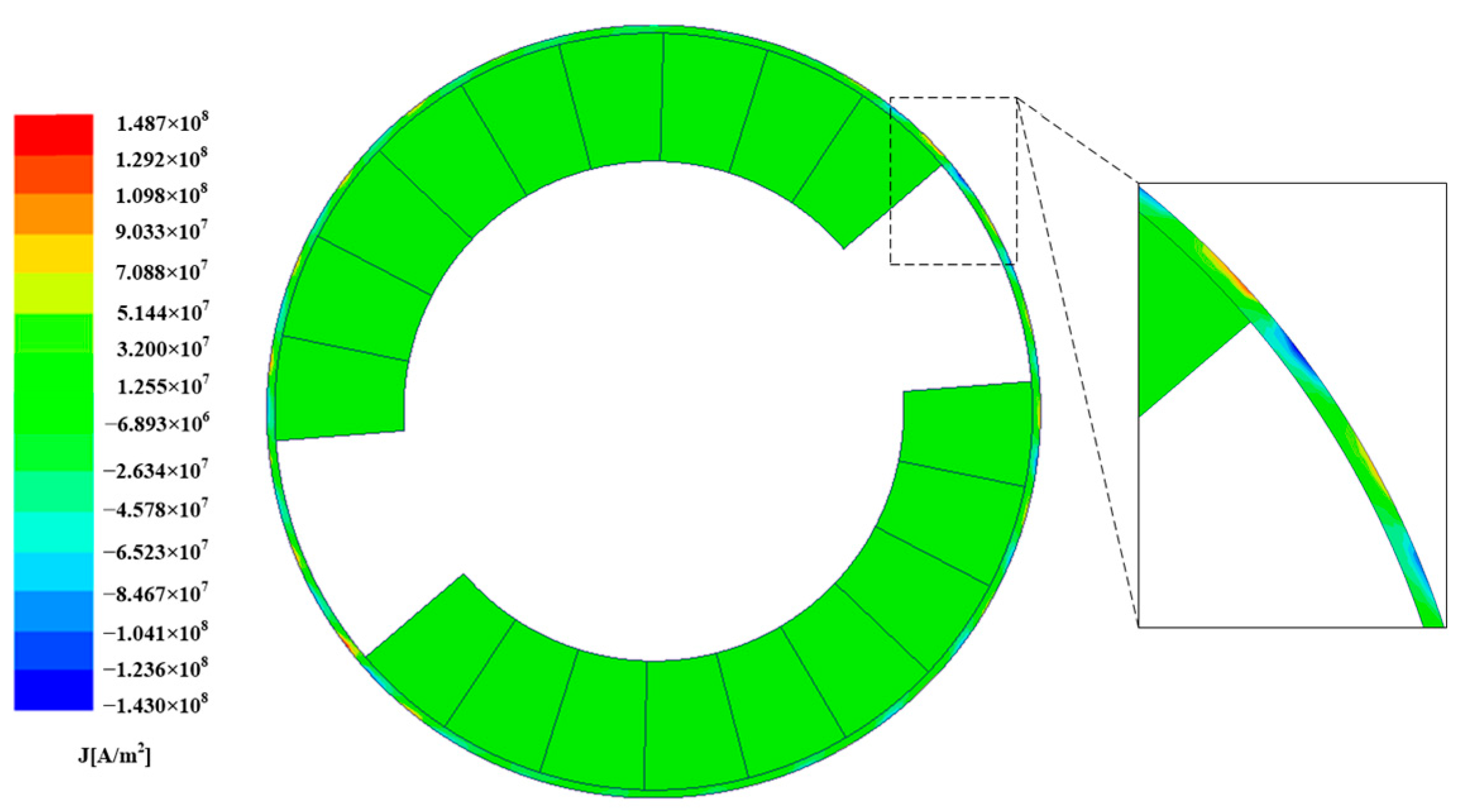
Different sleeve materials have different electrical conductivities, which will have a fundamental impact on the formation of the eddy current. The sleeve material has a certain ability to shield harmonics, so the conductivity of the sleeve plays a distributive role in the distribution of eddy current loss in the sleeve and permanent magnet. In general, the greater the conductivity of the sleeve, the smaller the proportion of eddy current loss in the total loss of the permanent magnet. This section mainly discusses the influence of the sleeve material on the magnetic density and the eddy current densities of the PM and the sleeve when the sleeve thickness is 1 mm.
Figure 16,
Figure 17 and
Figure 18 show the distribution of the magnetic eddy current densities of the sleeve and PM under 0.2 s load conditions for different materials.
The maximum eddy current density in
Figure 16 is 7.63 × 10
6 A/m
2, the rotor eddy current is mainly concentrated on the stainless-steel sleeve, and the PM has a small amount of eddy current distribution, which shows that the stainless-steel sleeve can partially shield the harmonic magnetic field of the air gap. According to
Figure 17, the eddy current of the rotor is mainly concentrated on the PM and sleeve, whereas the eddy current density of the PM is higher than that of the sleeve, with a maximum value of 1.93 × 10
6 A/m
2. It will increase the eddy current loss of the permanent magnet and further increase the temperature of the permanent magnet. As shown in
Figure 17, it is difficult for the carbon fiber to shield the harmonic magnetic field. In the case of a copper sleeve, almost all the eddy current density of the rotor is concentrated in the sleeve. Compared with the carbon fiber sleeve and the stainless-steel sleeve, there is almost no eddy current in PM. Therefore, the copper sleeve has good shielding effect and can effectively shield the harmonic magnetic field of the air gap magnetic field. The eddy current density of the sleeve is greatly increased, and the maximum value is 1.49 × 10
8 A/m
2, which increases the total eddy current loss.
Table 3 lists the eddy current loss of the rotor under different materials under load conditions and a sleeve thickness of 1 mm.
Table 3 shows that when the sleeve material is stainless steel, the eddy current loss is mainly concentrated on the sleeve, which is 243.21 W. The eddy current loss of the PM accounts for 6.6% of the total eddy current loss, which is only 17.19 W. When the sleeve material is carbon fiber, the total eddy current loss is greatly reduced, but the eddy current loss of the PM increases up to 45.7 W, accounting for 59.97% of the total eddy current loss, which indicates that the shielding effect of carbon fiber on the harmonic magnetic field is weak. When the sleeve material is copper, the total eddy current loss reaches up to 520.4 W and the eddy current loss of the PM is about 0 W, which can be considered insignificant, thus indicating that the copper sleeve almost shields the harmonic magnetic field of the air gap. According to the above comparison, it can be seen that the use of metal materials with high conductivity, such as stainless steel and copper, can effectively reduce the eddy current loss of the permanent magnet and have a strong shielding effect, but it will also produce large eddy current loss at the same time. Carbon fiber, which has low conductivity, has a poor shielding effect, but its eddy current loss is small.
4.3. Effect of Graphene Composite Sleeve Structure on Eddy Current Loss of Rotor
Graphene has excellent optical, electrical, and mechanical properties. It has important application prospects in materials science, micro-nano processing, energy, biomedicine, and drug delivery, and it is expected to be a revolutionary material in the future.
In this study, graphene was applied to the composite sleeve structure, and a graphene shielding layer was placed between the PM and the sleeve. Then, the influence of the graphene shielding layer on the eddy current loss of the rotor was analyzed.
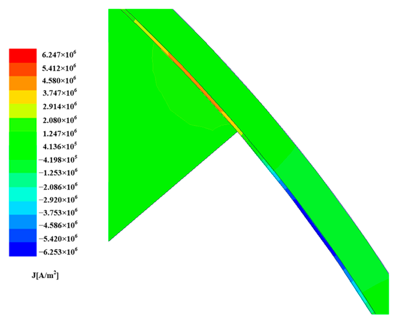
Figure 19 shows the partial distribution of the eddy current densities of 1 mm stainless-steel sleeve, the 0.1 mm graphene shielding layer, and the PM under load.
As shown in
Figure 19, the eddy current density distribution is mainly concentrated on the graphene shielding layer, and there is only a small amount of eddy current density in the sleeve and the PM. It can be inferred that graphene has a good shielding effect on the harmonic magnetic field. The rotor eddy current losses of the 0.1 mm and 0.2 mm graphene shielding layers under load are listed in
Table 4.
According to the comparison between
Table 3 and
Table 4, it is observed that after adding the graphene shielding layer between the permanent magnet and the sleeve, the eddy current loss of the sleeve and the permanent magnet is reduced to varying degrees. The eddy current loss is mainly concentrated on the shielding layer, which shows that the graphene shielding layer can effectively reduce the harmonic magnetic field of the air gap magnetic field. When the thickness of graphene is 0.1 mm, the eddy current loss of the shielding layer accounts for 79.9% of the total loss. When the thickness of shielding layer is 0.2 mm, the eddy current loss of shielding layer accounts for 84.7% of the total loss. It can be seen that the rotor eddy current loss increases with the increase of the thickness of the graphene shielding layer.
5. Conclusions
In this study, the eddy current loss of a 120-kW high-speed PM motor was calculated by the analytical method and the FEM analysis method. The main conclusions are as follows.
(1) Considering the space harmonics of the PWM current, when the frequency is between 200 Hz and 600 Hz, the variation trend of the rotor eddy current loss with the frequency obtained by analytical calculation and FEM analysis is roughly the same, and the error is still within a reasonable range. However, as the frequency continues to increase, the error between the two becomes larger and larger. At 1000 Hz, the error between them reaches 12.8%, and at 1200 Hz, it reaches 18.2%. The FEM simulation result of the rotor eddy current loss is much higher than the analytical calculation result. The reason for the error is that although the relationship between the eddy current loss and the frequency f in these two methods is directly proportional, the FEM analysis is more affected by frequency. In the case of low frequency, the difference between the two results is not large; with the increasing frequency, the error between the two will gradually increase.
(2) Neither of the methods consider the rotor eddy current loss caused by the end leakage; hence, both are smaller than the actual value. Under the condition of low frequency, the analytical calculation efficiency and accuracy is higher. However, at high frequency, the analytical calculation is limited, and the error in calculation results is large. Therefore, to improve the accuracy of the calculation results, it is necessary to carry out the three-dimensional modeling analysis of the rotor eddy current in the actual engineering calculation.
(3) This paper compares the distribution and size of the rotor eddy current loss under the condition of different sleeve materials. When the sleeve is made of stainless steel and copper, the eddy current loss of the permanent magnet is mainly concentrated on the sleeve; when the sleeve material is carbon fiber, the eddy current loss of the permanent magnet is greater than that on the carbon fiber sleeve. Due to the poor thermal conductivity of the carbon fiber and the eddy current loss of the permanent magnet being much larger than that of metal sleeve, it is easy to overheat the permanent magnet when the sleeve is made of carbon fiber and other composite materials, resulting in the demagnetization of permanent magnet. With the increase of the sleeve thickness, the eddy current loss of the rotor also increases.
(4) When the graphene shielding layer is added between the PM and the sleeve, the eddy current loss of the rotor mainly concentrates on the shielding layer. It can effectively shield the harmonic magnetic field, greatly reduce the eddy current loss of the PM, and prevent the rapid increase of the temperature of the PM, which is conducive to the continuous and stable operation of the high-speed PM motor.
In the next phase of the study, the author will measure the eddy current of the motor rotor under different sleeve materials according to the experimental prototype and compare the results with the above experimental results to further verify the correctness of the method proposed in this paper. At the same time, the author will propose a more effective structure to reduce the eddy current loss of the permanent magnets and a faster analysis method to calculate the eddy current loss.


