Abstract
In order to obtain a high power density, spacecraft usually use hollow-cup motors with trapezoidal air-gap magnetic field waveforms. However, due to structural issues, the hollow-cup motor has the problem that the waveform of the air-gap magnetic field is inconsistent with the ideal trapezoidal waveform, which causes torque ripples. In order to reduce torque ripples, the existing method only changes the structure of PMs; the changed PMs are difficult to magnetize and manufacture, which causes the air-gap magnetic field waveform to be unsuitable as the ideal waveform. This paper proposes a novel design of an inner rotor of a hollow-cup motor with an eccentric inner rotor based on the characteristics that the hollow-cup motor has inner and outer rotors and the two rotors rotate synchronously during operation. First, the influencing factors of the air-gap magnetic field are analyzed and the mathematical model of the eccentric inner rotor is established. Then, an eccentric model is established by finite element analysis, which proves that the eccentricity of the inner rotor can make the air-gap magnetic field waveform closer to the ideal trapezoid. Finally, a prototype based on the optimal eccentricity value is developed, verifying the effectiveness of the novel design of the inner rotor.
1. Introduction
With the rapid development of space technology, the requirements for the working performance of spacecraft are increasing, especially for high-resolution earth observation, satellite docking, rapid response and other tasks. The magnetically suspended control moment gyroscope (MSCMG) realizes attitude adjustment through the momentum exchange output torque of the high-speed rotor. It has the characteristics of high control accuracy and high reliability. In recent years, it has been extensively studied and has become the attitude control actuator of many spacecraft [1,2]. The performance of the motor that provides the angular momentum for MSCMG affects the accuracy of attitude control. The hollow-cup brushless permanent magnet motor has the advantages of being lightweight and having a high power density and no cogging torque pulsation. Therefore, in order to improve the accuracy and reduce power consumption, MSCMG mainly uses hollow-cup motors. At the same time, it has been widely used in other aerospace fields [3,4,5] and civilian fields [6,7]. At present, the hollow-cup motor with trapezoidal characteristics of air-gap magnetic field waveforms has the problem that the waveform does not match the ideal trapezoidal wave due to the problem of its own structure, which leads to torque ripples, which limit its high-precision rate servo application [8].
In order to solve the above problems, improving the air-gap magnetic field waveform is an important way to reduce torque ripple [9,10], and some studies have optimized the air-gap magnetic field of the motor [11,12,13,14,15,16,17,18,19,20,21,22,23,24]. In [11,12], the shape of PM was designed, and the equivalent surface current method was used to obtain the analytical calculation formula of the air-gap magnetic field when the outer arc of the tile-shaped PM is eccentric. In [13], two kinds of eccentric PMs were designed to optimize the trapezoidal wave waveform of the permanent magnet synchronous motor; at the same time, an improved method for the air-gap magnetic field model was proposed. In [14], PMs are optimized for eccentric design, and obtaining the eccentricity under the optimal solution by FEA proved that the design can effectively reduce the harmonic components of the air-gap magnetic field. In [15], through the chamfering design of PMs, the waveform of the air-gap magnetic field was optimized. In [16], a double-pole PM was proposed to optimize the air-gap magnetic field waveform and sawtooth torque.
In addition to optimizing the shape of PMs, interior motors mainly optimize the air-gap magnetic field waveform by optimizing the shape of the outer surface of the rotor. In [16], four different rotor shapes were designed, and the feasibility of improving the performance of the motor by changing the shape of the rotor was proved through experiments and finite element analysis. In [18], the outer diameter of the rotor was eccentrically designed, and the analytical solution of the air-gap magnetic field was obtained through conformal transformation. It was proved that the design could reduce the harmonic component and optimize the air-gap magnetic field waveform. In [19,20,21], the rotor surface was slotted design. This design can effectively reduce the harmonic components of the air-gap magnetic field and optimize the trapezoidal wave waveform and the cogging pulsation. In [22], a rotor shape of a permanent magnet synchronous motor was designed as an octagon; it was proved that the air-gap magnetic field waveform was improved and the harmonic content and ripple torque were reduced. In [23,24], through genetic algorithms and other algorithms, the motor structure was improved and the air-gap magnetic field waveform was optimized.
In summary, since the hollow-cup motor adopts the PMs surface mount structure, at present, there is only one method for optimizing the air-gap magnetic field waveform, that is, to change the PM shape. However, this involves problems of magnetization as well as manufacturing difficulties, resulting in an air-gap magnetic field waveform that cannot achieve the ideal waveform. In this paper, on the premise of not changing the shape of PMs, according to the characteristics that the hollow-cup motor is composed of inner and outer rotors and the relative position of the inner and outer rotors remains unchanged during operation, we propose a novel structure design of the inner rotor for the hollow-cup motor. Compared with changing the shape of PMs, this design avoids the magnetization and manufacturing problems of PMs. Firstly, the influencing factors of the air-gap magnetic field are analyzed through a mathematical model, and the model of inner rotor eccentricity is proposed and established. Then, the finite element model of the motor rotor is established, the trapezoidal wave quality under different eccentricity values is evaluated, and the optimal eccentricity value is obtained by analysis to make it as close as possible to the ideal waveform. Finally, a test prototype is made and through experiments and the effectiveness of the novel design is verified.
2. Mathematical Model of Motor Air-Gap Magnetic Field
A sectional view and a top view of the hollow-cup motor are shown in Figure 1. It is mainly composed of an inner rotor core, an outer rotor core, permanent magnets (PMs) and a hollow-cup stator. The PM is attached to the inner side of the outer rotor. Taking the hollow-cup motor in MSCMG as an example, the inner and outer rotors are fixed by the rotor fixing ring and connected to the flywheel. The cup-shaped stator is wound with windings and fixed on the gyro room, and the winding part is placed in the gap between the PMs and the inner rotor.
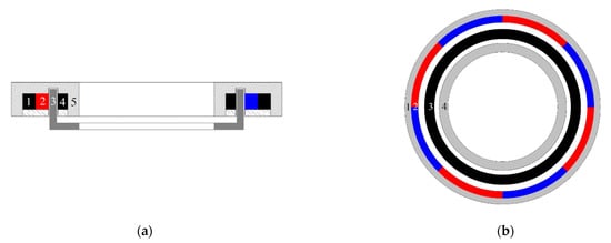
Figure 1.
Schematic diagram of hollow-cup motor: 1—outer rotor; 2—PMs; 3—cup stator; 4—inner rotor; 5—rotor fixing ring. (a) Axis section drawing of hollow-cup motor; (b) top view of bow-shaped PMs’ hollow-cup motor.
The air-gap magnetic field of the motor is excited by the PMs, and the surface current is used to replace the PMs by the equivalent surface current method; the integral method is then used to obtain the magnetic field generated by the equivalent surface current [25,26,27]. This paper mainly analyzes the magnetic field generated by the parallel magnetized magnets in the air gap.
The basic law of a constant magnetic field can be expressed by the following basic equation:
Since the divergence of the magnetic induction intensity B is always zero, a vector magnetic potential is introduced into the curl magnetic field, such that:
For a constant magnetic field, it is usually specified that:
In the motor, the magnetic field can usually be transformed into a two-dimensional parallel plane magnetic field for processing, and the motor is a centrosymmetric rotating structure; the current direction is thus the Z direction in the polar coordinate system. Combined with the above formula, we obtain:
From Equation (2),
where is the radial air-gap magnetic field and is the tangential air-gap magnetic field.
The general solution of Equation (4) is:
Using the separation of variables method to solve this equation, let:
Bring Equation (7) into Equation (6), and separate the variables:
where m is any constant, when m = 0:
When m ≠ 0,
Due to the centrosymmetric structure of the motor, the magnetic field in the motor is a periodic function about the ; m is thus a positive integer. Therefore,
where are constant, determined according to boundary conditions.
Then, according to the boundary conditions of the specific mathematical model, the constants in the air-gap magnetic field of the hollow-cup motor are determined. For the magnetic field produced by a single-ended wire at the center of the polar coordinate system, according to Ampere’s law:
Combine Formula (5):
Then:
In Figure 2a, the inner radius of the outer rotor is and the outer radius of the inner rotor is . Place a single long straight conductor at in the air gap of the motor. The vector magnetic potential generated by the conductor passing through the ferromagnetic boundary at any point in the air gap is:
At the interface between the air gap and the inner rotor, the tangential component of the air-gap magnetic field is 0:
At the interface between the air gap and the outer rotor, according to the tangential component of the air-gap magnetic field, the boundary conditions are:
By solving the boundary conditions:
Substitute Equations (14) and (18) into Equation (11), the vector magnetic potential of a single long straight wire at any point in the air-gap magnetic field can be obtained:
where: is the coordinate of point relative to point .
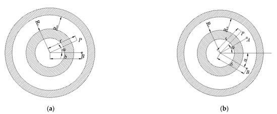
Figure 2.
Current carrying line in the air gap of a hollow-cup motor. (a) A current-carrying coil in the air gap; (b) a pair of current-carrying coils in the air gap.
The position of a pair of current-carrying coil element sides A and B in the air gap is in the space plane polar coordinate system, as shown in Figure 2b. Treat the current-carrying coil as two oppositely directed currents and add the resulting magnetic potentials, and a mathematical model of the magnetic field produced by a pair of current-carrying coils can be obtained:
Considering the centrifugal force, the magnetic steel is usually attached to the outer rotor, so that ; then:
Considering the centrifugal force, the magnetic steel is attached to the outer rotor:
Then, the radial flux density of a pair of coils in the air gap is:
The superposition calculation of the coils in the multi-stage coil can obtain the expression of the magnetic flux density produced by the interaction of the current-carrying coil in the air gap by 2p:
The equivalent surface current of the PMs is shown in Figure 3:
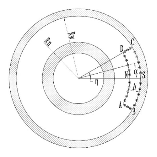
Figure 3.
Equivalent current of a tile magnet during parallel charging.
According to the equivalent surface current method, the surface currents of AB and CD along the surface of the magnet are equal in opposite directions; thus,
The surface currents along the AD side and BC side of the PM surface are in opposite directions and equal in magnitude, which is:
where is the angle of the PM, is the angle of the AD or BC side and is the coercivity.
Since the AB and CD sides are exactly the same,
The BC and AD edge-to-surface flow micro-elements are:
The equivalent coil current micro-element is , the radial length micro-element of the AB and CD sides of the PM is and the angle micro-element is .
It can be obtained from the above formula that the PM thickness , the PM inner diameter b, the outer rotor inner diameter , the inner rotor outer diameter and the number of pole pairs have an influence on the rotor air-gap magnetic field. When the number of pole pairs and the structure size of the motor is determined, the change in the air-gap magnetic field at any point in the air gap can be achieved through PM eccentricity or rotor eccentricity. However, it is difficult to magnetize and mechanize the PMs after eccentricity; the eccentric model of the inner rotor is thus designed in this paper.
Figure 4 shows the structure design of the inner rotor based on the eccentricity of the inner rotor. The eccentric structure design of the inner rotor is an eccentric design of the inner rotor outer diameter and the corresponding part of the outer rotor PMs. Move the center O of the outer diameter of the inner rotor to the position O’ in the opposite direction along the center line of the PM, keep the original end position of the outer diameter of the inner rotor unchanged and draw an arc with O’ as the center of the circle, which is the new outer diameter.
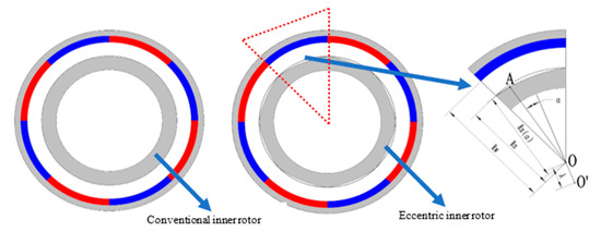
Figure 4.
Structural diagram of the eccentric design of the inner rotor.
From the geometric relationship, the position A() of any point on the outer diameter of the inner rotor can be obtained, where:
In the above formula, is the eccentricity value and is half of the opening angle of PMs.
Combining with Formulas (23) and (27)–(29), we can obtain the equivalent currents of p-pair PMs on the AB and CD sides, the BC sides, and the AD sides when the outer diameter of the inner rotor is eccentric. The magnetic flux density generated at the air gap () is
The is:
Then, integrate and sum the above formula to obtain the air-gap magnetic density produced by the PMs in the air gap:
From the above formula, when the size of the motor structure is determined, the air-gap magnetic field is only related to the eccentric value.
For trapezoidal waveforms, there is currently no effective evaluation index. In this paper, the trapezoidal wave waveform is evaluated based on the proportion of the top part τ, which is defined as:
where is the part above 99% of the maximum value of the air-gap magnetic field in one cycle of the air-gap waveform, and α is the half-cycle width of the air-gap waveform, as shown in Figure 5.
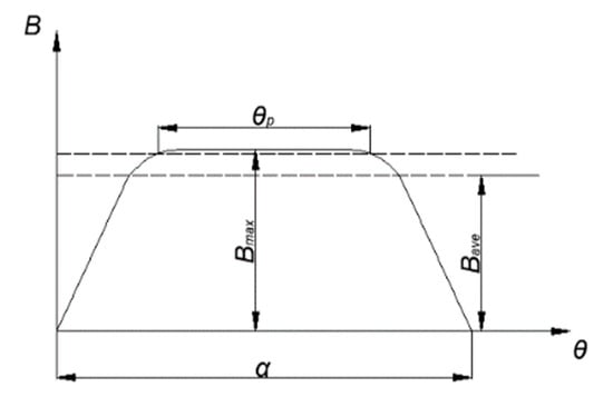
Figure 5.
Schematic diagram of flat top part proportions.
3. Finite Element Simulation Analysis
This paper discusses the simulation of the motor model used in the laboratory. The model parameters are shown in Table 1.

Table 1.
Hollow-cup motor model parameters.
The motor model was constructed in the Ansoft Maxwell, and the above-mentioned motor model was simulated to analyze the influence of the inter rotor eccentricity on the air-gap magnetic field waveform. The maximum length of the elements was set to 30 mm and the maximum number of elements was set to 30,000. The mesh is shown in Figure 6 and the magnetic map and magnetic line distributions are shown in Figure 7.
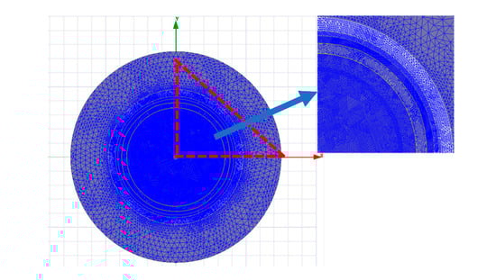
Figure 6.
Meshing diagram of the motor.
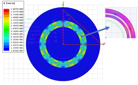
Figure 7.
Magnetic map and magnetic line distribution diagram of the motor under FEA.
Comparing the analytical results and the simulation results, the difference was about 1%, which proves the correctness of the model, as shown in Figure 8.
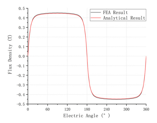
Figure 8.
Comparison of analytical results and FEA results.
A waveform analysis was carried out for different eccentricity values. The eccentricity range was 0~18 mm and the interval was 2 mm. The magnetic field waveform at the midpoint of the air gap under different eccentricities is shown in Figure 9.
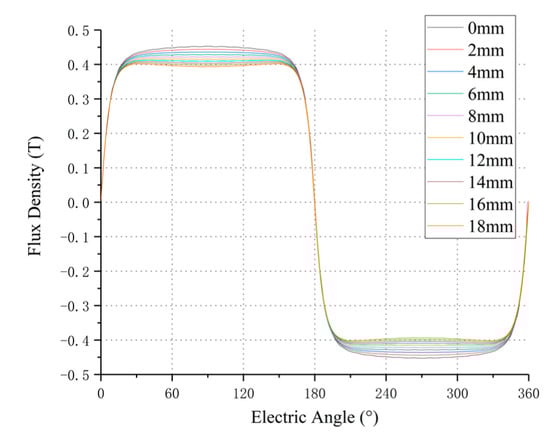
Figure 9.
Air-gap magnetic field waveform with different eccentricity values.
It can be concluded from Figure 9 that, with the increase in the eccentricity value, the flat top part of the air-gap magnetic field waveform gradually widened. When the eccentricity value increased to 14 mm, the air-gap magnetic field waveform was distorted.
According to Formula (1), we calculated the proportion of flat top under different eccentric values. When the eccentricity value was 0 mm, the was 58.8° and was 32.66%. The relationship between and eccentricity is shown in Figure 10. increased significantly with the increase in eccentricity within a certain range. The highest increase was from 32.66% in the 0 mm eccentric state to 70.34% in the 12 mm eccentric state, an increase of 115.37%. As the eccentricity value continued to increase, there was a decrease. The reason is that with the increase in the eccentricity value, the width of the air gap increases and the relative magnetic resistance increases, resulting in a decrease in the amplitude of the air-gap magnetic field, making the peak value of the waveform smaller and thus closer to the flat top. When the eccentricity value is too large, the reduction in the amplitude of the magnetic density of the air gap caused by the large magnetic resistance will be too large, and the phenomenon of depression will appear. Therefore, it can be concluded that within a certain range, the flat top width of the air-gap waveform increases with the increase in the eccentricity value of the outer diameter of the inner rotor, and the air-gap magnetic field waveform is optimized; the eccentricity value of 12 mm is the optimal solution in the model mentioned in this paper.
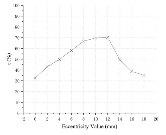
Figure 10.
The τ varies with the air-gap magnetic field.
A comparison of the air-gap magnetic field waveform before and after optimization under the eccentric value of 12 mm is shown in Figure 11.
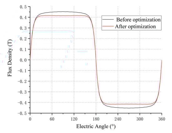
Figure 11.
Comparison before and after optimization of air-gap magnetic field at 12 mm eccentricity.
In summary, when the inner rotor was 12 mm eccentric, the half-cycle of the air-gap magnetic field was significantly flatter and the proportion of the flat top part was increased from 32.66% to 70.34%. This shows that the eccentric design of the rotor in the motor can effectively improve the waveform of the air-gap magnetic field: the proportion of the flat top part makes the air-gap magnetic field waveform closer to the trapezoidal wave, thereby improving the performance of the motor.
4. Prototype and Experiment
The prototype parameters are shown in Table 1, and the prototype is shown in Figure 12. It consists of inner/outer rotors and permanent magnets. The clamp fixes the inner and outer rotor cores and keeps the distance between them fixed. The permanent magnets are attached to the inner side of the outer rotor core. The prototype of the inner rotor under the optimal eccentricity value (12 mm) in the simulation and the prototype before optimal design were manufactured.
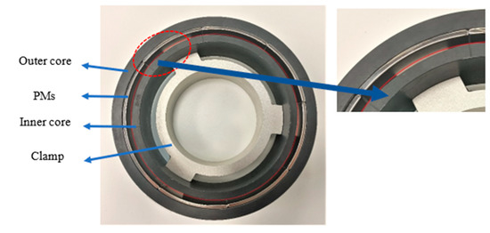
Figure 12.
Experimental sample of inner rotor eccentricity.
The experimental platform was mainly composed of fixtures, rotating platforms, magnetometers, brackets and control measurement devices, as shown in Figure 13. The test process was to install the prototype, adjust the position of the magnetometer probe, set the measurement parameters, perform the test and record the test data. The detailed testing process is as follows:
- (1)
- The clamping mechanism consists of a three-jaw centering chuck to fix the rotor and stator of the hollow-cup motor;
- (2)
- The rotating motor is fixedly connected with the three-jaw chuck to drive the three-jaw chuck to rotate;
- (3)
- The magnetometer uses the Hall effect to measure the magnitude and direction of the magnetic field, with a measurement accuracy of 0.001 T and a sampling of 36,000 points for each rotation of the prototype;
- (4)
- The manipulator clamps the magnetometer and adjusts the magnetometer probe to the middle of the air gap;
- (5)
- The measurement data is output as a two-dimensional array of angle points and magnetic field strength values.
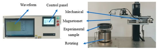
Figure 13.
Air-gap magnetic field test experimental platform.
The experimental test was carried out on the motor with an inner rotor eccentricity value of 12 mm, and the abnormal period data caused by the uneven magnetization of the PMs were eliminated. A comparison between the experimental results and the simulation results under 12 mm eccentricity is shown in Figure 14:
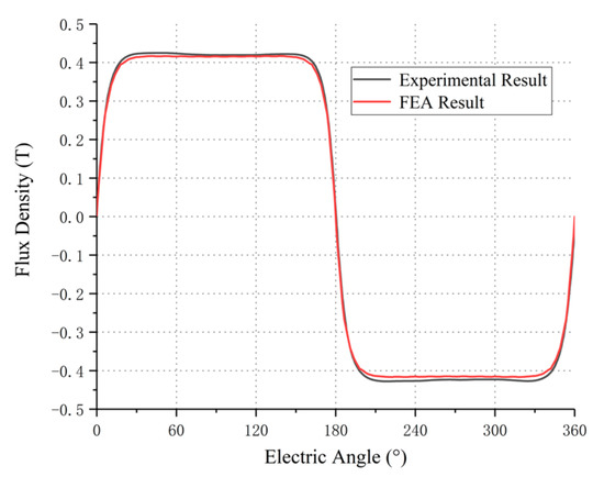
Figure 14.
Comparison of FEA results and experimental results.
When the eccentricity value was 12 mm, the was 123.68°, calculated by Formula (1); was 68.71% from Formula (1), which is different from the simulation value of 70.34% by −2.32%. The difference in was small, which verifies the correctness of the finite element simulation results.
The before the optimized design of the inner rotor was 66.99°; when the inner rotor eccentricity value was 12 mm, τ increased from 37.22% to 68.71%, which proves that the hollow-cup motor model based on the eccentricity of the inner rotor can effectively improve the shape of the air-gap magnetic field waveform and make it better adopt a trapezoidal shape. In order to achieve a more ideal waveform, the requirements for the machining accuracy of the eccentric inner rotor are high, but the current machining accuracy can meet the requirements. At the same time, compared with the design of PMs eccentric, it is more convenient for magnetization and manufacturing; the structure proposed in this paper therefore has a certain engineering application value.
5. Conclusions
In this paper, for the air-gap magnetic field of the hollow-cup permanent magnet brushless DC motor, a mathematical model was first established by the equivalent surface current method, and the analytical formula for the air-gap magnetic field after the inner rotor became eccentric was obtained. The finite element model of the inner rotor eccentric motor rotor was established, the air-gap magnetic field waveform of the model under different eccentric values was obtained, and the optimal eccentric value was obtained. Finally, an experimental prototype was prepared for verification and the experimental results and simulation results were coincident approximately. When the eccentricity was 12 mm, the simulation results show that, after the structural design, the change in τ before and after optimization was up to 115.37%. The test results show that the change in τ from before and after optimization was up to 110.38%. The results show that through the novel design of the inner rotor, the width of the flat top portion of the air-gap magnetic field can be effectively increased, and the trapezoidal characteristics of the air-gap magnetic field waveform of the hollow-cup motor can be improved so as to reduce the torque ripple of the motor.
Author Contributions
Conceptualization, J.S. and J.R.; methodology, J.S.; software, J.R.; validation, J.S., J.R. and H.S.; formal analysis, J.R.; investigation, H.S.; resources, J.S.; data curation, J.R.; writing—original draft preparation, J.R.; writing—review and editing, H.S.; visualization, J.S.; supervision, J.S.; project administration, J.S.; funding acquisition, J.S. All authors have read and agreed to the published version of the manuscript.
Funding
This work was supported by the National Nature Science Foundation of China, Grant/Award Numbers: 52075017, 62073010.
Institutional Review Board Statement
Not applicable.
Informed Consent Statement
Not applicable.
Data Availability Statement
Not applicable.
Acknowledgments
Not applicable.
Conflicts of Interest
The authors declare no conflict of interest.
Nomenclature
| Symbol | Parameter name |
| Top ratio of trapezoidal wave | |
| The part above 99% of the maximum value of the air-gap magnetic field | |
| The half-cycle width of the air gap waveform | |
| Magnetic induction intensity | |
| () | Magnetic vector potential (Z direction) |
| Magnetic field intensity | |
| Magnetoconductivity | |
| The curl of the magnetic field strength | |
| Polar radius | |
| Polar angle | |
| The radial air-gap magnetic field | |
| The tangential air-gap magnetic field | |
| Arbitrary constant | |
| The distance from the coil point to the center point (in Figure 6) | |
| | Constant |
| Permeability of vacuum | |
| Current in the current-carrying coil | |
| Radial distance | |
| The coordinates of any point relative to the point A(B) (in Figure 3) | |
| Inner radius of outer rotor | |
| Outer radius of inner rotor | |
| PM thickness | |
| Minimum air-gap thickness | |
| PM remanence | |
| PM coercivity | |
| Pole pairs |
References
- Montoya-Cháirez, J.; Santibáñez, V.; Moreno-Valenzuela, J. Adaptive Control Schemes Applied to a Control Moment Gyroscope of 2 Degrees of Freedom. Mechatronics 2018, 57, 73–85. [Google Scholar] [CrossRef]
- Sun, J.J.; Wang, C.E.; Le, Y. Research on a Novel High Stiffness Axial Passive Magnetic Bearing for DGMSCMG. J. Magn. Magn. Mater. 2016, 412, 147–155. [Google Scholar] [CrossRef]
- Praveen, R.P.; Ravichandran, M.H.; Sadasivan Achari, V.T. A Novel Slotless Halbach-Array Permanent-Magnet Brushless DC Motor for Spacecraft Applications. IEEE Trans. Ind. Electron. 2012, 59, 3553–3560. [Google Scholar] [CrossRef]
- Lee, H.I.; Noh, M.D. Optimal Design of Radial-Flux Toroidally Wound Brushless DC Machines. IEEE Trans. Ind. Electron. 2011, 58, 444–449. [Google Scholar] [CrossRef]
- Villani, M.; Tursini, M.; Fabri, G. High Reliability Permanent Magnet Brushless Motor Drive for Aircraft Application. IEEE Trans. Ind. Electron. 2012, 59, 2073–2081. [Google Scholar] [CrossRef]
- Aydin, M.; Gulec, M.; Demir, Y. Design and validation of a 24-pole coreless axial flux permanent magnet motor for a solar powered vehicle. In Proceedings of the 2016 XXII International Conference on Electrical Machines (ICEM), Lausanne, Switzerland, 4–7 September 2016; pp. 1493–1498. [Google Scholar]
- Takahashi, T.; Yasuda, Y.; Ohmoto, S. Proposal and development of radial air-gap coreless generator suitable for small wind turbine used in urban area. Electr. Eng. Jpn. 2010, 167, 26–34. [Google Scholar] [CrossRef]
- Chen, D.; Fang, J.C. Commutation Torque Ripple Reduction in PM Brushless DC Motor with Nonideal Trapezoidal Back EMF. Proc. CSEE 2008, 28, 79–83. [Google Scholar]
- Li, H.; Cui, L.; Ma, Z. Multi-Objective Optimization of the Halbach Array Permanent Magnet Spherical Motor Based on Support Vector Machine. Energies 2020, 13, 5704. [Google Scholar] [CrossRef]
- Yu, Y.; Cong, L.; Tian, X. Simultaneous suppression of torque ripple and flexible load vibration for PMSM under stator current vector orientation. IET Electr. Power Appl. 2019, 13, 359–369. [Google Scholar] [CrossRef]
- Meng, G.W.; Xiong, H.; Li, H.S. Calculation of big air-gap magnetic field in poly-phase multi-pole BLDC motor. In Proceedings of the 2008 International Conference on Electrical Machines and Systems, Wuhan, China, 17–20 October 2008; pp. 3224–3227. [Google Scholar]
- Meng, G.W.; Li, H.S. Analytical calculation for air gap flux density of multi-pole permanent magnetic brushless DC motor. Trans. China Electrotech. Soc. 2011, 26, 37–42. [Google Scholar]
- Chen, Z.F.; Xia, C.L.; Geng, Q. Modeling and Analyzing of Surface-Mounted Permanent-Magnet Synchronous Machines with Optimized Magnetic Pole Shape. IEEE Trans. Magn. 2014, 50, 8102804. [Google Scholar] [CrossRef]
- Xu, Y.Y.; Ge., H.J.; Jing., Y. Optimal design of eccentric magnet pole for permanent-magnet synchronous motors. J. Harbin Eng. Univ. 2013, 34, 873–877. [Google Scholar]
- Yu, Z.Y.; Li, Y.; Jing, Y.T. An Analytical Model for Magnetic Field Calculation of SPMSM with Chamfered Pole Considering Iron Core Saturation. IET Electr. Power Appl. 2020, 14, 1856–1864. [Google Scholar] [CrossRef]
- Shin, H.-S.; Jang, G.-H.; Jung, K.H. Optimal Design of Double-Pole Magnetization BLDC Motor and Comparison with Single-Pole Magnetization BLDC Motor in Terms of Electromagnetic Performance. Machines 2021, 9, 18. [Google Scholar] [CrossRef]
- Kim, H.S.; You, Y.M.; Kwon, B.I. Rotor Shape Optimization of Interior Permanent Magnet BLDC Motor According to Magnetization Direction. IEEE Trans. Magn. 2013, 49, 2193–2196. [Google Scholar] [CrossRef]
- Zhou, Y.; Li, H.S.; Ren, N.N. Analytical Calculation and Optimization of Magnetic Field in Spoke-Type Permanent-Magnet Machines Accounting for Eccentric Pole-Arc Shape. IEEE Trans. Magn. 2017, 53, 8107807. [Google Scholar] [CrossRef]
- Kang, G.H.; Hur, J.; Kim, W.B. The shape design of interior type permanent magnet BLDC motor for minimization of mechanical vibration. In Proceedings of the 2009 IEEE Energy Conversion Congress and Exposition, San Jose, CA, USA, 20–24 September 2009; pp. 2409–2414. [Google Scholar]
- Hur, J.; Reu, J.W.; Kim, B.W. Vibration Reduction of IPM-Type BLDC Motor Using Negative Third Harmonic Elimination Method of Air-Gap Flux Density. IEEE Trans. Ind. Appl. 2011, 47, 1300–1309. [Google Scholar]
- Lee, G.D.; Kang, M.C.; Kim, G.T. The equilibrium design of radial magnetic force for reduction of vibration in IPM type BLDC. In Proceedings of the 2015 IEEE International Electric Machines & Drives Conference (IEMDC), Coeur d’Alene, ID, USA, 10–13 May 2015; pp. 555–561. [Google Scholar]
- Waheed, A.; Ro, J.S. Analytical Modeling for Optimal Rotor Shape to Design Highly Efficient Line-Start Permanent Magnet Synchronous Motor. IEEE Access 2020, 8, 145672–145686. [Google Scholar] [CrossRef]
- Rahideh, A.; Korakianitisa, T.; Ruiz, P. Optimal brushless DC motor design using genetic algorithms. J. Magn. Magn. Mater. 2010, 322, 3680–3687. [Google Scholar] [CrossRef]
- Kamal, C.; Thyagarajan, T.; Kalpana, D. Multiobjective design optimization and analysis of magnetic flux distribution for slotless permanent magnet brushless DC motor using evolutionary algorithms. J. Magn. Magn. Mater. 2019, 476, 524–537. [Google Scholar]
- Tsai, W.B.; Chang, T.Y. Analysis of Flux Leakage in a Brushless Permanent-magnet Motor with Embedded Magnets. IEEE Trans. Magn. 1999, 35, 543–547. [Google Scholar] [CrossRef]
- Wu, L.J.; Li, Z.K.; Wang, D. On-Load Field Prediction of Surface-Mounted PM Machines Considering Nonlinearity Based on Hybrid Field Model. IEEE Trans. Magn. 2019, 55, 8100911. [Google Scholar] [CrossRef]
- Jang, S.M.; Ko, K.J.; Cho, H.W. Electromechanical Parameters Calculation of Permanent Magnet Synchronous Motor Using the Transfer Relations Theorem. IEEE Trans. Magn. 2007, 43, 2495–2497. [Google Scholar] [CrossRef]
Publisher’s Note: MDPI stays neutral with regard to jurisdictional claims in published maps and institutional affiliations. |
© 2022 by the authors. Licensee MDPI, Basel, Switzerland. This article is an open access article distributed under the terms and conditions of the Creative Commons Attribution (CC BY) license (https://creativecommons.org/licenses/by/4.0/).