Abstract
A turbojet engine is the most significant part of an Internal Combustion Engine (ICE) for Hybrid Electric Vehicles. Specifically, the coaxial-rotor unit is the key component, whose performance largely affects the working efficiency. Thereby, the fault diagnosis methods for coaxial-rotor units is a main focus. In line with our test results, the bearing circlip is the most vulnerable element while rotating. Moreover, the low-speed rotating fault diagnosis is even challenging for current methods. Since the fault diagnosis on the bearing circlip of coaxial-rotor units is absent, this paper establishes a test rig on a running coaxial-rotor unit under different working conditions. The three-directional vibration signals are collected and analyzed to demonstrate the working states. On the task of bearing circlip failure classification, a deep-learning-based model using the Bidirectional Gate Recurrent Unit and the Highway Network is developed, which is capable of capturing hidden features and removing unrelated information. For working performance evaluation, experiments on the data of different rotating speeds are carried out. Among all the fault diagnosis methods, our model is the best approach and achieves an average accuracy of 99.4%. The encouraging results reveal that the proposed model is effective in both the high-speed and low-speed fault diagnosis of bearing circlip malfunction.
1. Introduction
The automobile industry faces the challenge of saving energy and eliminating environmental damage, whilst delivering more goods and passengers to achieve a longer driving range [1]. In line with the ongoing advancements, electric vehicles, whose primitive form is proposed in 1900 s, have caused a revival of interest in vehicle engineering [2]. Based on the developing potential of electric vehicles and batteries, pure electric vehicles will ultimately meet the demands of high energy efficiency and low-pollutant emission. Despite its high energy efficiency and low-pollutant emission, the pure electric vehicle is currently a secondary choice for long-range driving restricted to battery storage capacity [3]. That is, these vehicle types are not likely to be widely used within the short term. Encouragingly, Hybrid Electric Vehicles (HEVs) bridge the gap between conventional vehicles and pure electric vehicles, which are viable means of transportation at present [4]. An HEV has an Internal Combustion Engine (ICE) as the main power source and an electric drive (i.e., a battery and an electric motor) to improve fuel economy [5]. Specifically, the battery required to power the electric motor is charged by the ICE without any external source. As such, almost all auto makers provide a hybrid version of their popular models such as Audi A8 Hybrid, Ford Fusion, Honda Civic Hybrid, and Hyundai Sonata Hybrid [6].
Typically, a turbojet engine, integrating with an electric generator, is employed in an ICE to supply stable and reliable power [7]. As long as the ICE aims to supply the steady-state power requirements, the turbojet engine, integrated with the electric generator, is employed, which is deemed best able to meet the demands of high power, light weight, and simple structure. Under the working condition of high temperature, high pressure, and high vibration, each component of the turbojet engine has to be sufficiently robust to failures [8]. The coaxial-rotor unit is one such key component, and it improves the efficiency of energy conversion to a large extent [9]. Effort on coaxial-rotor unit is ongoing to not just enhance its reliability but also investigate its working states. Thereby, fault diagnosis, which aims to detect and identify any kinds of potential abnormalities and faults of the working turbojet engine, is highlighted [10,11].
Notwithstanding, the high-speed rotary machinery often runs under time-varying speed, which results in a huge challenge for fault diagnosis [12]. Theoretically, fault diagnosis aims to analyze the consistency of the obtained underlying knowledge and the system characteristics measured from the monitored data [13,14]. In most cases, high-speed rotary machinery often runs under time-varying speed, which results in a huge challenge for fault diagnosis. Because the establishment of working conditions is demanding, few experiments are carried out on real laboratory coaxial-rotor units. For instance, the high rotating speed fluctuation of mechanical equipment may lead to an unpredictable frequency and the amplitude modulation of the signal [15]. Previous works have been engaged primarily in system modeling and simulating. In such work, the working state differs from the actual mode because it focuses on the target working parameters instead of reconstructing the working scenarios. Thus, fault diagnosis approaches, which are formulated dedicatedly for simulation models, cannot be directly applied to practical fault identification [7,16].
According to the high-speed rotating demand of the coaxial-rotor unit for the turbojet engine, issues of fault diagnosis are far from solved. Therefore, the objective of this paper is to detect and identify the fault of the rotating unit. Testing on an actual coaxial-rotor unit is carried out to reproduce the actual working states of the turbojet engine and generate fault data. A set of sensing devices is employed for working condition monitoring. The Hilbert–Huang Transform (HHT) is implemented, which aims to investigate the fault mechanism. A deep-learning-based framework is thus proposed for fault diagnosis. The Gate Recurrent Unit (GRU) [17,18] with the Highway Network [19,20] is applied to realize the motivation in a novel way. Our method is capable of exploiting the basic characteristics to represent the failures via the sensing signals. The contributions of this paper are threefold and can be summarized as follows:
- (1)
- A test rig for coaxial-rotor unit fault generation is established, based on which the working properties under different conditions are analyzed. Specifically, the bearing circlip failure is pronounced.
- (2)
- A novel fault diagnosis method is established, integrating the Bidirectional Gated Recurrent Unit and Highway Network. Our model aims to not just capture the internal features of the working state but also identify the faults of the coaxial-rotor unit with various rotating speeds.
- (3)
- In line with the practical working conditions, experiments are carried out on coaxial-rotor unit vibration signals to verify the effectiveness of the proposed model. Our model achieves decent working performance in the test.
2. Problem Formulation
2.1. Structure of Coaxial-Rotor Unit
Figure 1 presents the schematic of a turbojet engine. The major components of the engine are illustrated. The air from upstream comes through the centrifugal impeller of the compressor and reaches the diffuser. Via both the axial and radial diffusing, the air enters into the combustion chamber by passing the airhole. The combustion process is triggered by the ignition of the igniter, with the air mixing with the fuel. Hereafter, the high-pressure and high-temperature gas expands towards the turbine, which provides power to drive the spindle, the turbine, and the compressor rotating at high speed. Subsequently, the gas goes into the jet nozzle at lower pressure and a higher speed. In this way, the thrust is produced whilst the exhaust is discharged to the atmosphere [21].
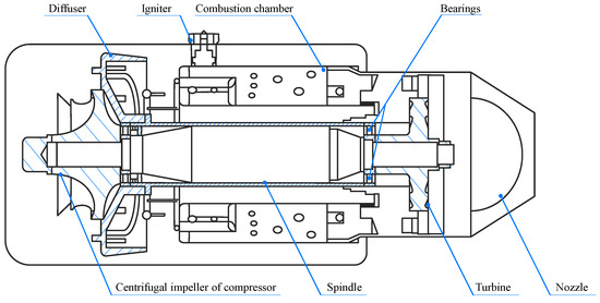
Figure 1.
A schematic diagram of a turbojet engine.
We shall thus detach the structure of turbojet engine to resolve the coaxial-rotor unit. According to Figure 2, regardless of the outer case, the coaxial-rotor unit consists of a spindle, the high-speed rotors, and the bearings. Apparently, in this system, the rotors are mainly the turbine and the compressor. Meanwhile, there is a ball bearing on each end of the rotor. Generally, the bearing is made up of high-speed ceramic with the inner and outer ring of bearing steel. An example of a coaxial-rotor unit is exhibited in Figure 3. The rotating speed of the coaxial-rotor unit is over 10,000 r/min, while the highest speed reaching 100,000 r/min. Due to the working principle of the turbojet engine, the bearings are set to protect the rotors and, in turn, are most likely to break down during working. Based on the previous investigations, the bearing failure is the most probable failure mode in practical use [22,23,24].
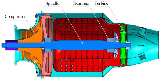
Figure 2.
The structure of a coaxial-rotor unit.
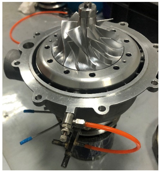
Figure 3.
An example of a coaxial-rotor unit.
2.2. System Establishment
As pointed out in the Introduction, the testing on the coaxial-rotor unit of the turbojet engine is a complex and interrelated process. For the task of fault diagnosis, the actual coaxial-rotor unit is built up and operated in various working states; see Figure 4. Note that we aim to concentrate on the condition of the coaxial-rotor unit, other components of the turbojet engine, including the combustion chamber and the ignition devices, are removed. The outlook of the coaxial-rotor unit in our experiment is presented in Figure 5a. Considering the impact from the combustion, high-temperature gas is generated and insufflated to simulate the practical working environment. The gas generator is attached to the coaxial-rotor unit via the pipelines seen in Figure 5b. Notably, the rotating speed varies due to the control of the air–gas ratio inside the gas generator. That is, by adjusting the proportional valve of the flow meter, the inputs of gas and air are regulated via a controlling module (Figure 5d), and thus their mixing ratio is revised. In this way, the rotation of the coaxial-rotor can be determined. For instance, the rotating speed reaches 20,000 r/min at an air–gas ratio of 26.8:4.5. A lubricating oil condition unit and a cooling water condition unit are employed to facilitate the system operation. Besides, the temperature of the exhaust is set as 50 °C at the initial stage.
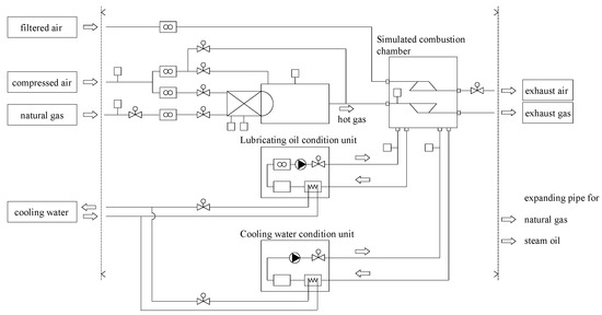
Figure 4.
The schematic layout of the coaxial-rotor unit.
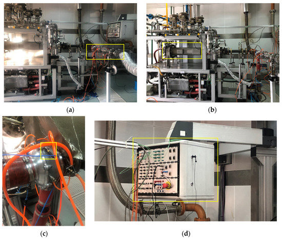
Figure 5.
A photograph of the test rig. (a) The coaxial-rotor unit; (b) the gas generator; (c) the vibration sensor; and (d) the air–gas ratio controlling module.
Sensing elements for detecting the working parameters are installed alongside the working components within the system. In the domain of measuring the rotating machinery, the vibration signal is most pronounced for characterizing the operational status directly. According to statistics, more than 70% of faults are manifested in the form of vibration [25]. In this way, to diagnose the potential faults, a three-axis vibrating acceleration sensor is attached to the rotor case. The specific installation position and sensor structure are shown in Figure 5c. The vibration of three directions—axial, radial, and tangential—is detected during working phases. With the power supplied, the vibrating signals are gathered by Integrated Circuits Piezoelectric (ICP) sensors 356A33 designed by PCB Piezotronics Inc. [26]. Sensing signals are transmitted through the 10-m low-noise cables. The data collecting and recording are implemented on an LMS830A analyzer. The measurement frequency is as high as 50 k Hz for dynamic signal detection. The signal acquisition time is 120 s and involves a whole work phase of the coaxial-rotor unit. The three-directional vibration signals are displayed in real time and kept for further analysis. In addition, a tungsten–rhenium thermocouple temperature sensor measures the temperature of the hot gas whilst a Hall speed sensor monitors the rotating. Figure 5 shows the photograph of the major components of the system. The specifications of the corresponding measurement devices are given in Table 1.

Table 1.
The specification of the measurement devices.
We find that the circlip of the bearing is the most vulnerable part during working; see Figure 6. Notably, according to recent publications, a great deal of attention is paid to the fault diagnosis of bearings of rotating machinery [27]. Research on bearing circlip failures is currently absent. Hence, we mainly focus on the identification of the bearing circlip malfunction of the coaxial-rotor unit in this work.
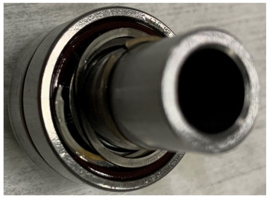
Figure 6.
The failure of the coaxial-rotor bearing circlip.
3. Preliminary Analysis
Generally, the coaxial-rotor unit rotating speed of turbojet engine ranges from 20,000 r/min to 60,000 r/min, with an interval of 5000 r/min. The working-states-based varying-speed signals can be measured. As an example, the time-domain vibration of the three dimensions in the normal state and bearing circlip failure, with a speed of 40,000 r/min, is illustrated in Figure 7a and Figure 7b, respectively.
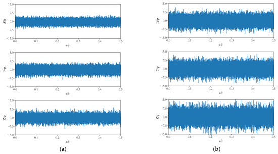
Figure 7.
An illustration of the vibration signal. The X-Axial vibration, Y-Radial vibration, and Z-Tangential vibration. (a) The three-directional vibration in the normal state; (b) the three-directional vibration in bearing circlip fault.
Firstly, the vibrating data properties are investigated to describe the damage mechanism. For rotating machinery, the output power varies within the natural frequency band during the damage, which indicates the fault condition. At this stage, the Hilbert marginal spectrum is established to analyze the vibrating signals of various rotating speeds. To the best of our knowledge, the HHT is capable of tackling structure damage data in a variety of tasks [28,29].
Basically, the HHT consists of two main procedures, namely, Empirical Mode Decomposition (EMD) and Hilbert Spectrum Analysis (HSA). The EMD technique is taken to decompose a given signal into a number of Intrinsic Mode Functions (IMF) that provide much time-frequency information to the narrowband [30]. Each IMF component contains local features of different time scales and meets certain conditions, based on which fault features can be extracted [31]. Subsequently, the Hilbert transform is carried out on each IMF to obtain the corresponding Hilbert spectrum. That is, these IMFs are conveyed into the time-frequency domain. Then, the IMFs’ entire Hilbert spectrum is aggregated to order the marginal spectrum derived in feature extraction [32]. In such a manner, the Hilbert marginal spectrum can be further used in fault diagnosis.
Let be the vibration signals of the coaxial-rotor unit. The EMD is employed to decompose to obtain a set of IMFs, which can be written as:
where stands for the IMF; is the number of IMF components; and is the residual function.
Then, the HHT is applied to each , so we have
From Equation (2), and can be integrated to obtain
where
and
The parameters , , and represent the instantaneous amplitude, instantaneous phase, and instantaneous frequency of the IMF, respectively.
Considering that is either a monotonic function or a constant, and no IMF component can be extracted from , the original signal can be rewritten as:
The time-frequency-amplitude distribution is described using Hilbert spectrum, which is:
Further, the Hilbert marginal spectrum is obtained by the time integral of the Hilbert spectrum (Equation (9)), which delivers the amplitude distribution of each instantaneous frequency.
Based on the Hilbert marginal spectrum, we define the Hilbert marginal spectrum energy as:
According to Equation (10), we see that the signal frequency characteristics is magnified in .
Since the vibration data of three directions are collected, the Hilbert marginal spectrum energy of the three-axis signal is the integration all these energies:
where is the weighting coefficient of the Hilbert marginal spectrum energy and satisfies:
The energy can be normalized to:
where represents the marginal spectrum energy value of the IMF component; is the energy normalization value; and is the order of the IMF.
Specifically, the Hilbert marginal spectrum energy of different rotating speeds is presented in Figure 8.
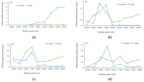
Figure 8.
The Hilbert marginal spectrum energy distribution (a) IMF1; (b) IMF2; (c) IMF3; and (d) IMF4.
In Figure 8, one can easily see that the marginal spectral energy drops dramatically with the increase of IMF order. Notably, the marginal spectral energies of IMF2, IMF3, and IMF4 are negligible since their values are smaller than 10-5. For IMF1, the Hilbert marginal spectrum energies of the normal state and bearing circlip failure are distinguished when the rotating speed reaches 35,000 r/min. We thus infer that the fault identification at a low speed is challenging due to the similarity of marginal spectrum energy distribution.
4. Fault Diagnosis Approach
4.1. Model Architecture
Aiming to identify the working state of the coaxial-rotor unit under different conditions, a fault diagnosis approach based on a Bidirectional Gated Recurrent Unit (Bi-GRU) and the Highway Network is proposed. The architecture of our model is presented in Figure 9.
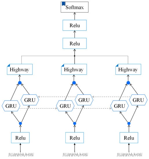
Figure 9.
The mode architecture.
Let , and represent the set of axial, radial, and tangential vibrating signals, respectively. can be the inputs of the proposed fault diagnosis model. Each input vector is sent to a fully connected layer for feature extraction. Specifically, the active function Rectified Linear Unit (ReLU) is exploited to transform the input into feature-based sequence, which is expressed as:
where and are weight matrix and bias vector derived from model training.
Similarly, and can be obtained in the same manner. The features of three-direction vibration are thoroughly distilled.
Then, the Bi-GRUs are taken to extract the internal properties of the input data. We will now briefly describe the theory of GRU. For details, see, for example, [17,19]. GRU is a variation of the Recurrent Neural Network (RNN), which is widely applied to learn sequential characteristics from a sequential data stream [33]. Concretely, a GRU is established on the gating mechanism to modulate the existing memory and new memory: a reset gate determines the combination of new input and previous information, and an update gate selects previous information to preserve [34]. The sigmoid activation function computes both gate outputs, while tanh is used as the candidate hidden activation function. Distinctively, the GRU controls the information flow and exposes the full hidden information without a memory unit [35]. In this way, the GRU is generally employed to obtain the hidden states of inputs.
In our model, a Bi-GRU related to sequence data is established. The input is fed into both a forward GRU and a backward GRU. These two GRUs of reverse timing are connected to one output. For the input , we have that:
where is the Bi-GRU output, consisting of forward hidden state and backward hidden state . Likewise, for inputs and , we can also compute and .
Furthermore, the Highway Network is introduced to deal with the outputs of Bi-GRU (i.e., , , and ). In a Highway Network, a part of the inputs can be pass through the layer straightly, while others are revised using gating units [36].
Supposing that is the transform gate and is the carry gate, for an input vector , the output of Highway Network is:
The computation of is facilitated by setting . Thereby, Equation (17) is modified to:
where is an affine transform followed by a non-linear activation function, and , , and are the parametric matrices optimized during training. Correspondingly, the outcomes and are computed as well.
With the application of Highway Network, more significant properties from vibrating signals are retained whilst irrelevant information properties are removed. The Highway Network outputs are concatenated and sent to the two-layer activation. The information propagation during this process is delivered as:
then
Lastly, fault identification is performed via a softmax classifier to obtain the probability distribution over the different working states, which is:
where is a trainable matrix, is the offset vector, and is the number of working states.
4.2. Model Training
The training of our model is conducted by using the cross entropy and regularization as the loss function:
where is the real working state distribution, and is the predicted one. The parameter is the weight of regularization. The gradients and other parameters are updated through back propagation with the learning rate :
5. Empirical Study
5.1. Experimental Setting
Fault classification experiments are conducted on data measured from coaxial-rotor units of real working conditions. The dataset contains three-directional vibration signals of both normal-state and bearing-circlip failure, with nine distinctive rotating speeds. The data are randomly split into training, validating, and testing according to the ratio 8:1:1.
Our model is finetuned using an ADAM optimizer with , , and . All the parameter matrices are generated within the distribution of randomly, while the bias is initialized as 0. The initialized parameters take 1000 times iteration for parameter optimization. Moreover, the hidden states dimension of the GRU cell is set as 256 with a learning rate of 0.001. The batch size and the training epoch are set to 10. The dropout rate is 0.5 to prevent overfitting. With respect to model training, the -regularization weight is set as 0.0001.
5.2. Experimental Protocol
In this experiment, the confusion matrix is taken as the evaluating metric to verify the working performance of our model. In a confusion matrix (Table 2), the basic parameters, accuracy, precision, and recall can be computed [37,38]. On the one hand, the index accuracy denotes the correctlyclassified samples of all the samples, which is:
Table 2.
The confusion matrix.
On the other hand, precision and recall also provide a richer measure of classification performance. According to Equation (27), precision stands for the proportion of predicted positive cases that are correctly real positives:
In contrast, recall refers to the proportion of real positives that are correctly predicted as positive:
In this experiment, ‘precision’ can be taken as a key metric for working performance demonstration. Normal working condition indicates ‘positive’, and failure indicates ‘negative’; it is more severe to classify a fault as a normal state than the opposite. Therefore, the accuracy is adopted as the primary evaluation index and precision as the auxiliary.
5.3. Main Results
The main purpose of the experiment is to verify the effectiveness of the proposed model for the aspect-level sentiment analysis. The following baseline methods are taken for comparison.
KNN (K—Nearest Neighbor): A simple machine learning algorithm for both linear and non-linear classification, which is insensitive to outliers.
SVM (Support Vector Machine): A supervised learning algorithm for generalized linear classification, which can prevent the issue of over fitting.
CNN (Convolutional Neural Network): A classical deep learning method, consisting of a convolutional layer, a pooling layer, and a fully connected layer for feature extraction.
LSTM (Long Short-Term Memory): A variant of RNN, which can detect the hidden states of the inputs.
GRU: As mentioned above, GRU is a variant of RNN that captures the hidden states using a gating mechanism and an activation function.
Bi-GRU: Bi-GRU is built based on a forward GRU and a backward GRU, to encode and decode the inputs, respectively.
Notably, five parameters are picked up as features and applied to KNN and SVM, which are the average value, standard deviation, maximum value, kurtosis, and IMF1 marginal spectral energy.
The fault diagnosis results of different rotation speeds are obtained. The test accuracy of all the working conditions is given in Table 3. The confusion matrix that presents test outcomes is shown in Figure 10. Notably, the values on the diagonal line refer to all the correctly recognized numbers of samples, corresponding to the accuracy of the test. The darker the color is, the higher the accuracy is.
Table 3.
The testing accuracy of the fault diagnosis.
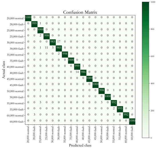
Figure 10.
The confusion matrix for the fault classification.
In nine evaluation settings, our model obtains the best and most consistent performance in classification accuracy. As presented in Table 3, an average accuracy as high as 99.4% is obtained due to its distinctiveness in both high-speed and low-speed rotating fault diagnosis. Among all the approaches, SVM and KNN have relatively lower accuracy than the deep learning models because current machine learning models still have challenges in feature extracting and exploiting. A deep neural network is taken as a better approach than machine learning algorithms in capturing the working properties under different working conditions. Specifically, one can easily see that the accuracy of low-speed diagnosis is even lower, which validates the analysis results based on Hilbert marginal spectrum energy.
6. Concluding Remarks
In this work, a deep-learning based fault diagnosis model is devised and deployed on the task of coaxial-rotor unit working state identification in a turbojet engine. To capture the essential characteristics of different states, the test rig is developed to reproduce the working condition and regenerate the fault data of the coaxial-rotor unit. Based on the test results, attention is paid to the faults on the bearing circlip, which are typically damaged at first. The three-direction vibration signals are measured and dedicatedly analyzed to characterize the working status. The HHT analysis is performed to study the failure mechanism of the bearing circlips. In line with the property of bearing circlip failure, a fault classification method, based on the integration of Bi-GRU and the Highway Network, is proposed. Basically, the GRU cells are capable of capturing the hidden information from inputs, while the Highway Network removes the unrelated features. The fault diagnosis performance of the proposed model is evaluated on nine different working conditions. An average accuracy of 99.4% of the proposed model is obtained, which outperforms the state-of-the-art methods. Specifically, our model also shows its superiority in low-speed fault classification. The experimental results indicate that our model obtains sufficient classification accuracy. That is, our model shows its distinctive superiority in dealing with the detected sensing signals precisely and thus can be applied to coaxial-rotor unit fault diagnosis tasks.
Author Contributions
Conceptualization, Z.P. and Y.W.; methodology, K.D.; software, K.D.; validation, K.D. and Z.P.; formal analysis, K.D. and X.H.; investigation, K.D. and X.H.; data curation, K.D.; writing—original draft preparation, Z.P.; writing—review and editing, Z.P.; visualization, K.D.; supervision, Z.P.; project administration, Y.W.; and funding acquisition, Y.W. All authors have read and agreed to the published version of the manuscript.
Funding
This research received no external funding.
Institutional Review Board Statement
Not applicable.
Informed Consent Statement
Not applicable.
Data Availability Statement
Not applicable.
Conflicts of Interest
The authors declare no conflict of interest.
Abbreviations and Nomenclature
| HEV | Hybrid Electric Vehicle |
| ICE | Internal Combustion Engine |
| GRU | Gate Recurrent Unit |
| ICP | Integrated Circuits Piezoelectric |
| PCB | Printed Circuit Board |
| HHT | Hilbert–Huang Transform |
| EMD | Empirical Mode Decomposition |
| HAS | Hilbert Spectrum Analysis |
| IMF | Intrinsic Mode Functions |
| Bi-GRU | Bidirectional Gated Recurrent Unit |
| ReLU | Rectified Linear Unit |
| RNN | Recurrent Neural Network |
| ADAM | Adaptive Moment Estimation |
| TP | True Positive |
| TN | True Negative |
| FP | False Positive |
| FN | False Negative |
| KNN | K-Nearest Neighbor |
| SVM | Support Vector Machine |
| CNN | Convolutional Neural Network |
| LSTM | Long Short-Term Memory |
| i-th IMF | |
| n-th residual function | |
| A | instantaneous amplitude |
| instantaneous phase | |
| instantaneous frequency | |
| the marginal spectrum energy value of IMF | |
| energy normalization value | |
| output of Bi-GRU | |
| forward hidden state | |
| backward hidden state | |
| transform gate of Highway Network | |
| carry gate of Highway Network | |
| parametric matrices optimized during training | |
| trainable matrix | |
| offset vector | |
| regularization |
References
- Tran, D.D.; Vafaeipour, M.; Baghdadi, M.E.; Barrero, R.; Hegazy, O. Thorough state-of-the-art analysis of electric and hybrid vehicle powertrains: Topologies and integrated energy management strategies. Renew. Sustain. Energy Rev. 2019, 119, 109596. [Google Scholar] [CrossRef]
- Haley, P. Effect of Electric Vehicles on Residential Distribution Systems. Bachelor’s Thesis, Louisiana State University, Baton Rouge, LA, USA, 2010. [Google Scholar]
- Tate, E.D. Techniques for Hybrid Electric Vehicle Controller Synthesis. Doctor’s Dissertation, University of Michigan, Ann Arbor, MI, USA, 2007. [Google Scholar]
- Borthakur, S.; Subramanian, S.C. Optimized Design and Analysis of a Series-Parallel Hybrid Electric Vehicle Powertrain for a Heavy Duty Truck. IFAC-PapersOnLine 2018, 51, 184–189. [Google Scholar] [CrossRef]
- Samuel; Ashwin, V. Energy Management System for a Hybrid Electric Vehicle. Master’s Dissertation, Lamar University, Beaumont, TX, USA, 2015. [Google Scholar]
- Canadian Automobile Association. Types of Electric Vehicles. Available online: https://electricvehicles.caa.ca/types-of-electric-vehicles/ (accessed on 29 May 2015).
- Zhao, Y.P.; Hu, Q.K.; Xu, J.G.; Bing, L.; Gong, H.; Pan, Y.T. A robust extreme learning machine for modeling a small-scale turbojet engine. Appl. Energy 2018, 218, 22–35. [Google Scholar] [CrossRef]
- Chen, Z.; Yuan, X.; Sun, M.; Gao, J.; Li, P. A Hybrid Deep Computation Model for Feature Learning on Aero-engine Data—Applications to Fault Detection. Appl. Math. Model. 2020, 83, 487–496. [Google Scholar] [CrossRef]
- Ji, Z.; Qin, J.; Guo, F.; Dang, C.; Zhang, S.; Dong, P. Effect of operating parameters on a hybrid propulsion system with high efficiency fueled by Kerosene for high altitude long endurance unmanned aerial vehicles. In Proceedings of the 2018 Joint Propulsion Conference, Cincinnati, OH, USA, 9–11 July 2018. [Google Scholar]
- Gao, Z.; Cecati, C.; Ding, S.X. A Survey of Fault Diagnosis and Fault-Tolerant Techniques—Part I: Fault Diagnosis with Model-Based and Signal-Based Approaches. IEEE Trans. Ind. Electron. 2015, 62, 3757–3767. [Google Scholar] [CrossRef]
- Dan, Q.; Liu, X.; Yi, C.; Ke, Z.; Hao, L. A Fault Diagnosis Approach Based on Deep Belief Network and Its Application in Bearing Fault. In Proceedings of the 2018 Chinese Intelligent Systems Conference; Springer: Singapore, 2018; pp. 289–300. [Google Scholar]
- Lu, S.; Wang, X. A new methodology to estimate the rotating phase of a BLDC motor with its application in variable-speed bearing fault diagnosis. IEEE Trans. Power Electron. 2018, 33, 3399–3410. [Google Scholar] [CrossRef]
- Li, H.; Wang, W.; Huang, P.; Li, Q. Fault diagnosis of rolling bearing using symmetrized dot pattern and density-based clustering. Measurement 2020, 152, 107293. [Google Scholar] [CrossRef]
- Gao, Z.; Cecati, C.; Ding, S.X. A Survey of Fault Diagnosis and Fault-Tolerant Techniques—Part II: Fault Diagnosis With Knowledge-Based and Hybrid/Active Approaches. IEEE Trans. Ind. Electron. 2015, 62, 3768–3774. [Google Scholar] [CrossRef]
- Yin, J.; Zhao, W. Fault diagnosis network design for vehicle on-board equipment of high-speed railway: A deep learning approach. Eng. Appl. Artif. Intell. 2016, 56, 250–259. [Google Scholar] [CrossRef]
- Zhao, Y.P.; Song, F.Q.; Pan, Y.T.; Li, B. Retargeting extreme learning machines for classification and their applications to fault diagnosis of aircraft engine. Aerosp. Sci. Technol. 2017, 71, 603–618. [Google Scholar] [CrossRef]
- Bahdanau, D.; Cho, K.; Bengio, Y. Neural machine translation by jointly learning to align and translate. arXiv 2014, arXiv:1409.0473. [Google Scholar]
- Chung, J.; Gulcehre, C.; Cho, K.H.; Bengio, Y. Empirical evaluation of gated recurrent neural networks on sequence modeling. arXiv 2014, arXiv:1412.3555. [Google Scholar]
- Yang, C.; Jiang, M.; Jiang, B.; Zhou, W.; Li, K. Co-Attention Network with Question Type for Visual Question Answering. IEEE Access 2019, 7, 40771–40781. [Google Scholar] [CrossRef]
- Lin, L.; Luo, H.; Huang, R.; Ye, M. Recurrent Models of Visual Co-Attention for Person Re-Identification. IEEE Access 2019, 7, 8865–8875. [Google Scholar] [CrossRef]
- Ji, Z.; Qin, J.; Cheng, K.; Liu, H.; Zhang, S.; Dong, P. Performance evaluation of a turbojet engine integrated with inter-stage turbine burner and solid oxide fuel cell. Energy 2019, 168, 702–711. [Google Scholar] [CrossRef]
- Dadouche, A.; Rezaei, A.; Wickramasinghe, V.; Dmochowski, W.; Bird, J.W.; Nitzsche, F. Sensitivity of Air-Coupled Ultrasound and eddy current sensors to bearing fault detection. Tribol. Trans. 2008, 51, 310–323. [Google Scholar] [CrossRef]
- Rezaei, A.; Dadouche, A.; Wickramasinghe, V.; Dmochowski, W. A comparison study between acoustic sensors for bearing fault detection under different speed and load using a variety of signal processing techniques. Tribol. Trans. 2010, 54, 179–186. [Google Scholar] [CrossRef]
- Rezaei, A.; Dadouche, A. Development of a turbojet engine gearbox test rig for prognostics and health management. Mech. Syst. Signal Processing 2012, 33, 299–311. [Google Scholar] [CrossRef]
- Jin, X.; Yang, H.; Wang, H. Fault Diagnosis for Civil Aviation Engine Test Based on the Vibration Signal. Procedia Eng. 2012, 29, 3002–3006. [Google Scholar] [CrossRef][Green Version]
- PCB Model 356A33. Available online: https://www.pcb.com/products?m=356A33 (accessed on 25 September 2017).
- Zhao, X.; Jia, M.; Lin, M. Deep laplacian auto-encoder and its application into imbalanced fault diagnosis of rotating machinery. Measurement 2019, 152, 107320. [Google Scholar] [CrossRef]
- Huang, N.E.; Shen, Z.; Long, S.R.; Wu, M.C.; Shih, H.H.; Zheng, Q.A. The empirical mode decomposition and Hilbert spectrum for nonlinear and nonstationary time series analysis. Proc. Math. Phys. Eng. Sci. 1998, 454, 903–995. [Google Scholar] [CrossRef]
- Song, D.; Liu, X.; Huang, J.; Zhang, J. Energy-based analysis of seismic failure mechanism of a rock slope with discontinuities using Hilbert-Huang transform and marginal spectrum in the time-frequency domain. Landslides 2021, 18, 105–123. [Google Scholar] [CrossRef]
- Li, C.; Yu, G.; Fu, B.; Hu, H.; Zhu, Q. Fault Separation and Detection for Compound Bearing-Gear fault Condition Based on Decomposition of Marginal Hilbert Spectrum. IEEE Access 2019, 7, 110518–110530. [Google Scholar] [CrossRef]
- Jia, W.; Diao, M.; Jiang, L.; Huang, G. Fluctuating Characteristics of the Stilling Basin with a Negative Step Based on Hilbert-Huang Transform. Water 2021, 13, 2673. [Google Scholar] [CrossRef]
- Yi, C.; Lin, J.; Zhang, W.; Ding, J. Faults Diagnostics of Railway Axle Bearings Based on IMF’s Confidence Index Algorithm for Ensemble EMD. Sensors 2015, 15, 10991–11011. [Google Scholar] [CrossRef]
- Lipton, Z.C.; Berkowitz, J.; Elkan, C. A Critical Review of Recurrent Neural Networks for Sequence Learning. Available online: http://arxiv.org/abs/1506.00019 (accessed on 17 October 2015).
- Dey, R.; Salemt, F.M. Gate-variants of gated recurrent unit (GRU) neural networks. In Proceedings of the 2017 IEEE 60th International Midwest Symposium on Circuits and Systems (MWSCAS), Boston, MA, USA, 6–9 August 2017; pp. 1597–1600. [Google Scholar]
- Dang, L.M.; Sadeghi-Niaraki, A.; Huynh, H.D.; Min, K.; Moon, H. Deep Learning Approach for Short-Term Stock Trends Prediction Based on Two-Stream Gated Recurrent Unit Network. IEEE Access 2018, 6, 55392–55404. [Google Scholar]
- Srivastava, R.K.; Greff, K.; Schmidhuber, J. Highway networks. arXiv 2015, arXiv:1505.00387. [Google Scholar]
- Powers, D. Evaluation: From Precision, Recall and F-Measure to Roc, Informedness, Markedness & Correlation. J. Mach. Learn. Technol. 2011, 2, 37–63. [Google Scholar]
- Fawcett, T. An introduction to ROC analysis. Pattern Recognit. Lett. 2006, 27, 861–874. [Google Scholar] [CrossRef]


Publisher’s Note: MDPI stays neutral with regard to jurisdictional claims in published maps and institutional affiliations. |
© 2022 by the authors. Licensee MDPI, Basel, Switzerland. This article is an open access article distributed under the terms and conditions of the Creative Commons Attribution (CC BY) license (https://creativecommons.org/licenses/by/4.0/).