Abstract
This paper aims to present the design of a new 3D-printed continuously variable transmission (CVT) developed for an electric vehicle prototype competing in Shell Eco-marathon electric battery category, a world-wide energy efficiency competition sponsored by Shell. The proposed system is composed of a polymeric conic geared friction wheel assembled in the motor axle and directly coupled to the rear tire of the vehicle. The conical shape allows to implement a continuous variation of the geared friction wheel diameter in contact with the tire. The motor with the geared friction wheel was mounted over a board with linear bearings, allowing the speed ratio to change by moving the board laterally. A computational simulation model of a prototype electric vehicle with the proposed 3D-printed CVT was created in Matlab/Simulink environment to obtain the traction force in the geared friction wheel and also to analyze the vehicle performance. The simulation results demonstrated possibilities of increasing vehicle speed range output and available torque in the rear traction wheel. Also, it is shown with the simulated model that the designed CVT consumes 10.46% less energy than a fixed transmission ratio, demonstrating the CVT concept’s potential for battery consumption reduction. Lastly, a 3D-printing slicing software with an optimization algorithm plug-in was used to determine the best printing parameters for the conic geared friction wheel based on the tangential force, maximum displacement and safety factor. When compared to the original part with a 100% infill density, the optimized solution reduced the component mass by about 12% while maintaining safe mechanical resistance and stiffness.
1. Introduction
The automotive industry has been heavily reliant on the use of fossil fuels for decades. However, due to rising diesel and gasoline prices, as well as environmental pollution and fossil fuel depletion, it was concluded that alternate vehicle propulsion methods were required. Electric vehicles (EVs) have been intensively studied and appear as a possible solution for reducing global warming emission gases in this scenario. To put it in perspective, the transportation industry alone accounts for over 30% of global warming emissions in the United States, thus switching to electric vehicles would be a very responsible and environmentally sound option [1]. International conferences, such as the United Nations Framework Convention on Climate Change (UNFCCC), also show international pressure for the development of sustainable technologies. According to Miyamoto [2], the Kyoto Protocol, which was signed in 1997, had an indirect impact on climate change discussion by boosting the number of worldwide patent applications for renewable energy, emphasizing the need for international cooperation on the subject.
The Shell Group sponsors an international competition called the Shell Eco-marathon, which focuses on lowering vehicle fuel consumption and is competed in by university groups of enthusiastic automobile teachers and students all over the world [3,4,5,6,7,8]. This and similar events foster several automotive technology developments, including the demonstration of distinctive car designs [9,10,11], energy management systems [12,13,14,15,16], powertrain innovations [17,18,19,20], advanced use of materials and manufacturing methods [21,22], mechanical design [23,24,25,26,27] and the development of new 3D-printed automotive parts [28,29,30,31,32,33].
Significant scientific effort has been put toward inventing vehicle transmissions that lower an automobile’s energy usage over the previous three decades. Again, this initiative is a direct result of the growing environmental concern that has imposed mandates on existing car makers and users to reduce exhaust emissions and boost vehicle economy [34,35]. A continuously variable transmission (CVT) provides a continuous range of transmission ratios between predetermined limits, improving a vehicle’s fuel economy and dynamic performance by better matching engine operating conditions to variable driving circumstances [36]. The most common type of CVT in automotive applications uses two pulleys connected by a belt or chain [37,38]; however, several other designs, each having their own characteristics, have also been used at times (e.g., spherical, toroidal, ratcheting, hydrostatic, electrical, cone, epicyclic, magnetic and others kinds of CVTs; cf. [39,40]). The fundamental concepts, mathematical models and computing approaches have been explored exhaustively and research challenges and key difficulties in dynamic modeling, design and control of such CVTs have been analyzed [37,41,42,43,44,45]. However, although a CVT is an important part of the strategy for improving vehicle fuel efficiency, its full potential in mass-produced and competition vehicles has yet to be realized, especially in a world where lighter and more efficient concepts are constantly sought.
Additive manufacturing (AM) and 3D printing technologies are rapidly changing machinery engineering as we know it, allowing for more creativity and freedom in machine design innovation, with numerous advantages over traditional manufacturing [46]. Free and widely distributed computer-aided design (CAD) and manufacturing (CAM) software tools, and well established computer numerical control (CNC) standards, combined with readily available and affordable commercial 3D printers and materials, are fueling an increase in the number of users and potential applications of these technologies, including powertrain and other automotive components [47,48]. While almost anyone with a basic understanding of 3D modeling and printing can create their own self-made parts and devices, the wide design freedom in terms of geometry and materials, as well as professional quality assurance, raises a slew of new complex engineering questions and scientific uncertainties that go beyond basic design and functionality. Due to the design and manufacturing versatility of 3D printing, as well as continuous change and evolution in the range of available materials, the development and application of 3D-printed powertrain components is still in its infancy, but research and development activities underway promise alternative feasible and breakthrough solutions.
In response to society’s desire for efficient and environmentally friendly small automotive vehicles, this study proposes to design and validate a new 3D-printed CVT enabling improved powertrain efficiency with a simpler, lighter, and cheaper design than existing options for EV prototypes. The competition and EV prototype’s essential specifications are presented first, with the main requirements for transmission design identified, followed by the required engineering calculations and analysis. Next, the analysis and results obtained with the computational vehicle simulation model and the optimized printing parameters for the CVT gear manufacturing are shown. Lastly, the key findings and conclusions are drawn.
2. Materials and Methods
2.1. The Competition Circuit and Basic Rules
At the Shell Eco-Marathon, prototype vehicles must complete a 12 km distance in less than 28 min, which equates to 10 turns on the circuit depicted in Figure 1. As a result, an average speed of 25.71 km/h is required to complete the circuit without exceeding the time limit. Normally, the circuit’s speed limit is set between 0 and 35 km/h.
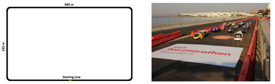
Figure 1.
Circuit diagram and image of the Brazilian start line for the Shell Eco-marathon competition (5 m wide rectangular circuit with 90° curves with an 8 m radius).
The energy consumption unit commonly used for conventional vehicles with internal combustion engines (ICE) is a physical unit of fuel volume per unit distance, such as liters per 100 km (l/100 km). In the case of EVs, energy consumption is evaluated in kWh per unit distance in km (kWh/km) [49]. At the Shell Eco-marathon, the most energy-efficient vehicle that wins the competition is the one that completes the entire distance on the circuit in the allotted time while consuming the least amount of energy; fuel, in the case of ICE vehicles, or battery, in the case of EVs.
During the edition of the Shell Eco-marathon that took place in 2017 in Brazil, a speed profile was recorded using a GPS in a prototype vehicle from the Milhas Gerais team. This driving cycle was used as an input to the computational model built.
2.2. Transmission Concepts and Design
The vehicle’s output speed is affected by the motor’s input speed, the transmission speed ratio and the tire diameter. For simplicity, the prototype EV transmission system was first idealized with a fixed speed ratio, in which a geared friction wheel was directly connected to the tire of the rear wheel, eliminating the need for gear shifting and the construction and implementation of a more complex driveline system. In this architecture, when the throttle is pressed by the pilot, signals are sent to the motor controller to change the motor speed, and consequently the wheel rotation. In the case of DC electric motors, the speed range can vary from zero to thousands of rotations per minute (rpm) depending on the voltage received from the motor controller. The first geared friction wheel prototype design is shown in Figure 2a. This component was 3D printed and assembled in a prototype vehicle in order to validate the reliability of a plastic geared friction wheel in the vehicle’s powertrain. However, this solution harmed the performance and efficiency of the EV’s powertrain, affecting acceleration time, top speed, available torque at the wheels, and energy consumption. Indeed, the narrow output speed range obtained with this design in comparison to the torque required to start the vehicle demonstrated the importance of a variable transmission.
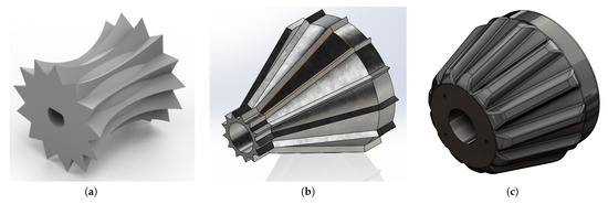
Figure 2.
Geared friction wheel design concepts: (a) first wheel attempt, (b) idealized conic wheel and (c) final wheel (left to right by order of appearance).
The simplest implementation of a variable transmission system began with an idealized conic geared friction wheel, as illustrated in Figure 2b. This component was originally assembled in the motor axle and directly coupled to the vehicle’s rear tire. If the electric motor is assembled with the proper inclination angle and on a movable platform, the conical shape would allow the geared friction wheel diameter in contact with the tire to gradually increase. As a result, the solution was to mount the motor on a board with linear bearings, allowing the speed ratio to be varied by lateral movement of the board. To move the motor base and thus the geared friction wheel, a system of strings and pulleys connected to a lever system can be attached to the board. When necessary, the pilot may pull or push this lever, thereby changing the speed ratio. The first conic geared friction wheel designed, shown in Figure 2b, was able to achieve the proposed speed range; however, its geometric format was not properly designed to handle the contact force with the vehicle rear tire, resulting in teeth fractures, wear and loss of performance. The EV prototype and idealized variable transmission concept employing the final geared friction wheel design in Figure 2c is shown in Figure 3.
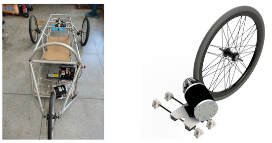
Figure 3.
EV prototype (left) and virtual representation of the idealized CVT concept (right).
The maximum and minimum gear speed ratios u from the variable transmission can be obtained considering the wheel tire diameter D and the maximum and minimum values of the conic geared friction wheel diameter d, given by
The vehicle speed as a function of the transmission ratio u and angular velocity of the electric motor , where n is the rotating velocity of the electric motor in rpm, from which the limiting EV speeds can be determined, is given by
Similar relations can be established to determine torque magnification at the output wheel. The corresponding torques on the wheel tire and the geared friction wheel, and , respectively, can be determined according to the rated power of the electric motor P and the transmission efficiency , yielding
Considering an intermediary value of the electric motor speed rpm and the output wheel tire diameter mm, according to Equations (1) and (2) it is possible to define the maximum and minimum diameters of the conic geared friction wheel that assure the required speed range for the circuit. The minimum and maximum geared friction wheel diameters chosen were mm and mm and the corresponding gear speed ratios found were max 6.99:1 and min 4.99:1. Considering an electric motor with rated power W and adopting, for simplicity, the transmission efficiency , as shown in Figure 4, Equations (2) and (3) can be used to determine the variation of the vehicle’s speed and output wheel torque as a function of the geared friction wheel diameter.
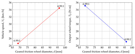
Figure 4.
Vehicle output speed and output wheel torque as a function of the conic geared friction wheel diameter (transmission ratio); the CVT ranges from the value of = 6.99:1 to = 4.99:1.
2.3. Vehicle Dynamic Model and Performance
As previously stated, the geometric format of the first conic geared friction wheel design shown in Figure 2b was not designed to withstand the contact force generated by the vehicle’s rear tire, resulting in teeth fractures, wear, and performance loss. To gain a better understanding of the forces and torques acting on the vehicle’s powertrain and to evaluate the proposed CVT, a computational model of the EV prototype was developed and is described in what follows.
The aspects of a vehicle’s design which affect the dynamics can be grouped into drivetrain and braking, suspension and steering, distribution of mass, aerodynamics and tires. To model longitudinal vehicle dynamics and study forward vehicle motion in response to driver inputs, propulsion system outputs, ambient conditions, air/surface/water conditions, and other factors, a simplified one degree of freedom lumped mass model and Newton’s second law are used [49,50], yielding
where m is the vehicle total embedded mass, is the time derivative of the vehicle speed (acceleration), is the traction force, is the aerodynamic drag force, is the rolling resistance force and the road angle considered for calculating the gravitational force component in the vehicle movement direction; these forces have been well established in [49,51] and can be defined as
where is the aerodynamic drag, is the air mass density, is the projected frontal area of the vehicle, is the wind speed, and the rolling resistance coefficient; further info and details on these parameters can be consulted in [51]. The parameters in the above equations and vehicle data used in this study are defined in Table 1; the road angle and the wind speed were considered equal to zero.

Table 1.
Operational and physical characteristics of the vehicle.
The transmission in a powertrain provides the transmission (or speed) ratios needed to match the engine’s torque and speed range to the vehicle’s torque and speed requirements. It thus transmits power with some losses while also converting from an input torque and speed product to nominally the same power product at the output but with a different combination of torques and speeds. According to the longitudinal vehicle model previously defined, to better understand the forces and torques acting on the vehicle powertrain and also to evaluate the proposed CVT, a computational simulation model was implemented in Matlab/Simulink environment as shown in Figure 5.
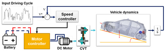
Figure 5.
Schematics of the computational simulation model of the EV prototype considering a longitudinal dynamic model and a continuous variable transmission (CVT).
To simplify the model, the transmission losses by friction, gear slipping and elastic deformation were neglected, hence, 100% efficiency was adopted. The computational model uses a predefined array of speeds as input that defines the driving cycle. The speed ratio in the simulation is calculated according to the reference speed and the geared friction wheel diameter selected in a lookup table, created with the maximum and minimum geared friction wheel diameters versus vehicle output speed shown in Figure 4. The block vehicle dynamics portrays the vehicle longitudinal dynamics established in Equations (4) and (5). In the computational model, a proportional-integral speed controller was also implemented to play the pilot’s role. The proportional and integral gains defined for this controller were and , respectively. Furthermore, a DC motor controller was implemented to command the motor speed, changing the motor mean voltage with the variation of a PWM (pulse-width modulation) duty cycle informed by the speed controller. The duty cycle determines how long the signal is in a high state. If the duty cycle is equal to 50%, the mean voltage on the motor will be half of the source voltage. So, in accordance with the changes in duty cycle, the mean voltage varies, controlling the motor speed.
According to [52], the battery model used in the EV prototype can be defined by its state of charge (SOC) and its voltage V,
where AH represents the available capacity of the battery and its nominal capacity, i.e., a fully charged battery has a SOC of 100% and a fully discharged one has a SOC of 0%. Therefore, by integrating the product between the current required by the motor and the voltage obtained in Equation (7), it is possible to extract the energy consumption.
2.4. 3D Printing Concepts and Methods
The final geared friction wheel design depicted in Figure 2c was produced using polymer AM technologies, which involve layering materials to create objects from 3D model data via material extrusion, in which the material is selectively dispensed through a nozzle or orifice. The process is called FDM (fused deposition modeling; a trademark of the company Stratasys), and it is a material extrusion process that uses heated extrusion and layer deposition of materials to create thermoplastic parts. In its untrademarked form, the FDM process is also referred to as FFF (fused filament fabrication), and is typically associated with a less industrial grade technology (desktop, hobbyist level 3D printing technology). The 3D printer model used is the widely accessible, low-cost and hobbyist grade technology, Anet A8. To determine the optimal printing parameters for the STL part file generated from the 3D geometric model of the geared friction wheel, a commercially available plug-in and tool called SmartSlice (Version 21.0.28) was used. It is designed to be used with Ultimaker’s Cura slicer (Version 4.11.0) software and incorporates an optimization algorithm. To ensure structural requirements are met, the software is fed with the force acting on the component, the component’s maximum displacement, and the desired safety factor. Additionally, this plug-in makes use of modifier meshes to reinforce infill density in critical regions without requiring the entire body to be reinforced with additional material.
The Table 2 compares the mechanical properties of PETG to those of some of the most commonly used filaments in 3D printing from the 3Dlab brand. Although PLA is stronger than PETG, PETG is better suited for outdoor use due to its resistance to weather and sunlight. PETG has a temperature tolerance of approximately 75 °C. On the other hand, 3D printed parts made of PLA must be kept below 55 °C to avoid thermal deformation and stiffness relaxation. The black PETG with 1.75 mm of diameter from 3DFila was chosen as the material for the final version of the geared friction wheel. The printing temperature set for this material was 240 °C with the built plate temperature adjusted to 65 °C.
Table 2.
Typical materials properties values and printing parameters used with FDM printers.
3. Results
3.1. General Driving Cycle Simulation
The results for a general driving cycle simulation with a maximum speed of 35 km/h are shown in Figure 6. The graphics show the variable transmission speed ratio according to the vehicle speed. The reference speed is plotted with a constant blue line and the red line is the simulated model actual speed. As presented in Figure 6, for speeds below 24.61 km/h, the implemented transmission ratio will be limited to 6.99:1. When more speed is required, the speed ratio is continuously changed. The maximum speed of the vehicle is obtained with the speed ratio of 4.99:1 and the maximum speed error between the reference profile and the simulated model speed curve occurred in the vehicle acceleration stage and was less than 2 km/h. This error is related to the controller gains selected and its value is smaller than the value obtained by [53].
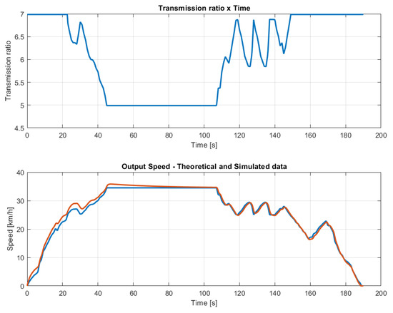
Figure 6.
Transmission ratio and output speed comparison for a general driving cycle.
Considering the motor rated power of 1000 W, it is also possible to obtain from the simulation of the computational model the traction force according to the general input driving cycle. Accordingly, Figure 7 shows the traction force plot where the maximum and minimum forces are 621.78 N and 317.26 N, respectively.
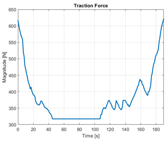
Figure 7.
Vehicle traction force for the general driving cycle.
The traction force acquired from simulation was used to obtain the tangential force applied to the surface of the geared friction wheel teeth. Furthermore, a second version of the conic geared friction wheel (see Figure 2c) was designed with reinforced teeth and with smooth fillets. Considering the tangential force and trying to obtain better gear strength with reduced component mass, Cura slicer software with an optimization printing tool was used to evaluate the best printing parameters for the geared friction wheel. This subject is presented in Section 3.3.
3.2. Shell Eco-Marathon Circuit Driving Cycle Simulation
Figure 8 shows the speed profile recorded by the Milhas Gerais team during the Shell Eco-marathon competition. The actual vehicle model speed compared to the speed reference from the used driving cycle is shown in Figure 9. The maximum speed error between the input driving cycle and the simulated vehicle speed curve was observed to be 1.96 km/h.
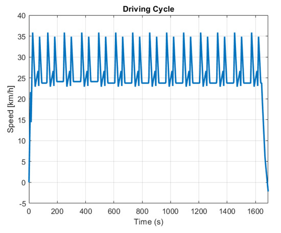
Figure 8.
Recorded speed profile (driving cycle) during the 2017 Brazilian edition of the Shell Eco-marathon competition.
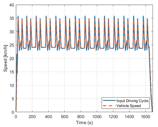
Figure 9.
The competition reference driving cycle and the simulated vehicle model speed.
By integrating the product between the current required by the motor and the voltage obtained in Equation (7), it is possible to extract the energy consumption for the fixed-ratio transmission model and for the CVT as shown in Figure 10. As shown, the simulated model with the designed CVT consumed 10.54% less energy than the simulated model with the fixed transmission ratio. This result validates the variable transmission’s development efforts and demonstrates the concept’s potential for battery consumption reduction.
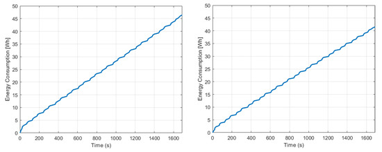
Figure 10.
Energy consumption: geared friction wheel design with fixed ratio (left) and variable ratio CVT (right).
These results demonstrate that the vehicle’s overall efficiency can be enhanced with improved powertrain systems, with fewer rotating components (reducing rotating inertia) as obtained with the CVT concept presented as compared to conventional CVT models. Moreover, the vehicle weight can be reduced by applying 3D-printed components, which also contributes to energy saving. Lastly, losses related to friction can be addressed with new components design and the use of new materials enabled by AM.
3.3. 3D Printing Optimization
Initially, in the SmartSlice software, a structural simulation was performed just by fixing the center of the gear hole and applying a distributed force on the teeth flanks. The total force used was equal to 621.78 N and was obtained considering the maximum traction force and the respective transmission ratio discussed in the previous section. The software then calculates the safety factor and the maximum displacement for this situation. The values obtained are shown in Table 3. In this first step, the maximum displacement found was 0.24 mm. Therefore, for optimization, it was decided to define as constraints the value of 0.3 mm for the maximum displacement and a safety factor of 1.5.
Table 3.
3D printing optimization parameters and comparison of results.
As shown in Table 3, by adjusting the printing parameters to its optimized setting it was possible to reduce the mass from 437.2 g to 386.7 g, maintaining an acceptable maximum displacement and guarantying the safety factor previously stipulated. Figure 11 illustrates the geared friction wheel slicing process before and after optimization where it is possible to verify the mesh reinforcement close to the teeth surface. Moreover, local reinforcements were used in the part holes. Due to local reinforcement complexity, the printing time in the optimized configuration was approximately 40 minutes higher for a printing speed of 60 mm/s; however, it is not critical in this project, since the main concern is about improving the geared friction wheel mechanical strength and stiffness.
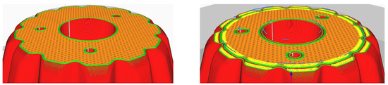
Figure 11.
3D printed geared friction wheel slicing comparison: initial (left) and optimized slicing (right) performed with the 3D printing software Cura slicer from Ultimaker; the red lines denote external shell surface, orange and yellow the infill regions, and green the inner wall.
4. Conclusions
The present work proposes a new CVT architecture utilizing a conic geared friction wheel. This wheel engages with the rear wheel’s tire and is coupled to the electric motor axle. The speed ratio change is obtained moving the motor, which is mounted over a movable board with linear bearings. The proposed variable transmission is unprecedented and its constructive simplicity suggests opportunities for application in small vehicles. A computational model was implemented to simulate a prototype 3-wheeled vehicle with this designed transmission. It is shown with the simulated model that the designed CVT consumes 10.46% less energy than a fixed transmission ratio, demonstrating the CVT concept’s potential for battery consumption reduction. Furthermore, an optimization algorithm was used to obtain optimized printing parameters for manufacturing the geared friction wheel in PETG. The obtained set of parameters demonstrated possibilities to reduce the geared friction wheel mass about 12% in relation to the 3D-printed geared friction wheel with 100% of material infill without loosing mechanical resistance and stiffness. In future work the EV prototype will be tuned and tested in a real-driving cycle. To determine the powertrain’s efficiency, data on speed, time, motor current, battery voltage, and battery consumption will be collected. Additional testing will be conducted to determine the transmission’s efficiency and durability.
Author Contributions
Conceptualization, T.P.B.; methodology, M.R.C.C. and T.P.B.; software, M.R.C.C. and T.P.B.; validation, M.R.C.C. and T.P.B.; formal analysis, T.P.B. and C.M.A.V.; resources T.P.B. and C.M.A.V., data curation, M.R.C.C.; writing—original draft, M.R.C.C.; writing—review and editing, T.P.B. and C.M.A.V.; Supervision, T.P.B.; Project administration, T.P.B.; funding acquisition, T.P.B. All authors have read and agreed to the published version of the manuscript.
Funding
This research received no external funding.
Data Availability Statement
Not applicable.
Acknowledgments
The first two authors gratefully acknowledge the support of the National Council for Scientific and Technological Development—CNPq, the Center of Innovation, Research and Teaching of Mechatronics—NIPEM and also the Federal University of São João del-Rei—UFSJ. The third author gratefully acknowledges the support provided by the Foundation for Science and Technology (FCT) of Portugal, within the scope of the project of the Research Unit on Materials, Energy and Environment for Sustainability (proMetheus, https://tech.ipvc.pt/unidades.php?u=PROMETHEUS, accessed on 3 August 2021), Ref. UID/05975/2020, financed by national funds through the FCT/MCTES.
Conflicts of Interest
The authors declare no conflict of interest.
References
- Reddy, K.J.; Natarajan, S. Energy sources and multi-input DC-DC converters used in hybrid electric vehicle applications—A review. Int. J. Hydrogen Energy 2018, 43, 17387–17408. [Google Scholar] [CrossRef]
- Miyamoto, M.; Takeuchi, K. Climate agreement and technology diffusion: Impact of the Kyoto Protocol on international patent applications for renewable energy technologies. Energy Policy 2019, 129, 1331–1338. [Google Scholar] [CrossRef]
- Alnunu, N.; Said, S.; Al-Sharman, S.; Al-Ibrahimi, A.; AbdulAziz, A.; Hellabi, M.A.; Touati, F.; Ghani, S.; Mahdi, E.S.; Benammar, M. Design of Qatar University’s first solar car for Shell Eco-Marathon competition. In Proceedings of the 2012 First International Conference on Renewable Energies and Vehicular Technology, Nabeul, TN, USA, 26–28 March 2012; pp. 49–54. [Google Scholar] [CrossRef]
- Baldissera, P.; Delprete, C. Human powered vehicle design: A challenge for engineering Education. ASME ESDA2014-20549. In Proceedings of the ASME 2014 12th Biennial Conference on Engineering Systems Design and Analysis, Copenhagen, Denmark, 25–27 July 2014. [Google Scholar] [CrossRef]
- Buck, L.; Mclening, C.; Burgess, J. Eco-car: A perfect vehicle for technical design teaching? In Proceedings of the 16th International Conference on Engineering and Product Design Education (E&PDE14), Design Education and Human Technology Relations, University of Twente, Enschede, The Netherlands, 4–5 September 2014. [Google Scholar]
- Abdulwahed, M.; Ahmad, S.; Hasna, M.O.; Ghani, S.; Benammar, M. Contribution of Shell Eco-Marathon engineering design experience to soft skills development: A qualitative analysis in the Asian context. In Proceedings of the 2014 International Conference on Interactive Collaborative Learning (ICL), Dubai, United Arab Emirates, 3–6 December 2014. [Google Scholar] [CrossRef]
- von Solms, S.; Nel, H. Reflective learning in engineering education: A case study of shell Eco-Marathon. In Proceedings of the 2017 IEEE International Conference on Industrial Engineering and Engineering Management (IEEM), Singapore, 10–13 December 2017. [Google Scholar] [CrossRef]
- Verma, A.R.; Chaurasia, A.; Jaiswal, S.S.; Bhonde, L.; Guha, R.; Sahu, H.; Patel, S.; Banthiya, S.; Maddeshiya, S.; Mirzapure, S.; et al. Team AVERERA’s Alterno V4.0–A Hyper Energy-Efficient Electric Prototype Vehicle for Shell Eco-Marathon; SAE Technical Paper 2021-01-0792; SAE International: Warrendale, PA, USA, 2021. [Google Scholar] [CrossRef]
- Fabian, M.; Puškár, M.; Boslai, R.; Kopas, M.; Kender, Š.; Huňady, R. Design of experimental vehicle specified for competition Shell Eco-marathon 2017 according to principles of car body digitisation based on views in 2D using the intuitive tool Imagine&Shape CATIA V5. Adv. Eng. Softw. 2018, 115, 413–428. [Google Scholar] [CrossRef]
- Gunadi; Fergianto, F. Designing Shell Eco-Marathon car bodies with SolidWorks. J. Physics Conf. Ser. 2020, 1700, 012072. [Google Scholar] [CrossRef]
- Ary, A.K.; Sanjaya, Y.; Prabowo, A.R.; Imaduddin, F.; Nordin, N.A.B.; Istanto, I.; Cho, J.H. Numerical estimation of the torsional stiffness characteristics on urban Shell Eco-Marathon (SEM) vehicle design. Curved Layer. Struct. 2021, 8, 167–180. [Google Scholar] [CrossRef]
- Brusaglino, G.; Buja, G.; Carello, M.; Carlucci, A.; Onder, C.; Razzetti, M. New technologies demonstrated at Formula Electric and Hybrid Italy 2008. World Electr. Veh. J. 2009, 3, 160–171. [Google Scholar] [CrossRef]
- Carello, M.; Bertipaglia, A.; Messana, A.; Airale, A.G.; Sisca, L. Modeling and Optimization of the Consumption of a Three-Wheeled Vehicle; SAE Technical Pape 2019-01-0164; SAE International: Warrendale, PA, USA, 2019. [Google Scholar] [CrossRef]
- Gechev, T.; Punov, P. Driving strategy for minimal energy consumption of an ultra-energy-efficient vehicle in Shell Eco-Marathon competition. IOP Conf. Ser. Mater. Sci. Eng. 2020, 1002, 012018. [Google Scholar] [CrossRef]
- Punov, P.; Gechev, T. Energy management of a fuel cell hybrid ultra-energy efficient vehicle. Int. J. Hydrogen Energy 2021, 46, 20291–20302. [Google Scholar] [CrossRef]
- Stabile, P.; Ballo, F.; Mastinu, G.; Gobbi, M. An ultra-efficient lightweight electric vehicle—Power demand analysis to enable lightweight construction. Energies 2021, 14, 766. [Google Scholar] [CrossRef]
- Wasselynck, G.; Auvity, B.; Olivier, J.C.; Trichet, D.; Josset, C.; Maindru, P. Design and testing of a fuel cell powertrain with energy constraints. Energy 2012, 38, 414–424. [Google Scholar] [CrossRef]
- Cichoński, K.; Jezierska-Krupa, K.; Gleń, M.; Skarka, W. The comparative study of drivetrain of high-performance electric vehicle. Diagnostyka 2014, 15, 65–70. [Google Scholar]
- Nassif, G.G.; de Almeida, S.C. Impact of powertrain hybridization on the performance and costs of a fuel cell electric vehicle. Int. J. Hydrogen Energy 2020, 45, 21722–21737. [Google Scholar] [CrossRef]
- Carello, M.; Pinheiro, H.C.; Longega, L.; Di Napoli, L. Design and Modelling of the Powertrain of a Hybrid Fuel Cell Electric Vehicle; SAE Technical Pape 2021-01-0734; SAE International: Warrendale, PA, USA, 2021. [Google Scholar] [CrossRef]
- Messana, A.; Sisca, L.; Ferraris, A.; Airale, A.; de Carvalho Pinheiro, H.; Sanfilippo, P.; Carello, M. From Design to Manufacture of a Carbon Fiber Monocoque for a Three-Wheeler Vehicle Prototype. Materials 2019, 12, 332. [Google Scholar] [CrossRef]
- Sethi, N.; Chauhan, P.; Bansal, S.; Singari, R.M. Robust vehicle development for student competitions using fiber-reinforced composites. In Lecture Notes in Mechanical Engineering; Springer: Singapore, 2021; pp. 61–76. [Google Scholar] [CrossRef]
- Ferraris, A.; Messana, A.; Multari, D.; Sisca, L.; Airale, A.G.; Carello, M. Steering System of a Low-Consumption Vehicle: From the Dynamics Analysis to the Design of the Wheel Assembly. In Advances in Italian Mechanism Science. IFToMM ITALY 2018. Mechanisms and Machine Science; Carbone, G., Gasparetto, A., Eds.; Springer: Berlin/Heidelberg, Germany, 2018; Volume 68, pp. 91–99. [Google Scholar] [CrossRef]
- Zhai, G.; Liang, Z.; Li, M. Study on the Optimization Model of a Flexible Transmission. Math. Probl. Eng. 2019, 2019, 1–12. [Google Scholar] [CrossRef]
- Iliev, S.; Gunev, D.; Mitev, E. Design and Development of a Steering Wheel for an Energy Efficient Vehicle. In Proceedings of the International Symposium on Intelligent Manufacturing and Automation, Vienna, Austria, 23–26 November 2019; pp. 0405–0414. [Google Scholar] [CrossRef]
- Kral, J.; Palko, M.; Palko, M.; Pavlikova, L. Design and development of ultra-light front and rear axle of experimental vehicle. Open Eng. 2020, 10, 232–237. [Google Scholar] [CrossRef]
- Gilewski, M.; Czarnigowski, J.; Górski, W.; Mitrus, K.; Różyło, P.; Trocha, S.; Wypychowski, M. Strength analysis of the drive wheel hub of a hydrogen-powered prototype hyper-light vehicle. J. Phys. Conf. Ser. 2021, 1736, 012056. [Google Scholar] [CrossRef]
- Soto, P.A.; Collet, M.; Bauduin, S.; Fernandez Sanchez, E.F.; Aguilera, A.M.; Duysinx, P. Topology optimization of mechanical components fabricated by additive manufacturing for a Shell Eco-Marathon vehicle. In Proceedings of the 12th World Congress of Structural and Multidisciplinary Optimisation, Braunschweig, Germany, 5–9 June 2017. [Google Scholar]
- Hands, C.H.; du Plessis, A.; Minnaar, N.; Blakey-Milner, B.A.; Burger, E. Can Additive Manufacturing Help Win the Race? Preprints 2018, 2018110040. [Google Scholar] [CrossRef]
- Sosnowski, M.; Skarka, W. Optimization of a Composite Beam-Based Load Bearing Structure, for an Ultra-Efficient Electric Vehicle. In EngOpt 2018 Proceedings of the 6th International Conference on Engineering Optimization; Springer: Berlin/Heidelberg, Germany, 2018; pp. 1073–1082. [Google Scholar] [CrossRef]
- Yankov, E.; Kamarinchev, D.; Minev, R.; Minev, E. Optimal Build Inclination in 3d Printing–Shell Eco–Marathon Rapid Prototyping Car Parts Case7. Proc. Univ. Ruse 2019, 58, 51–58. [Google Scholar]
- Junk, S.; Dorner, M.; Fleig, C. Additive Manufacturing of Continuous Carbon Fiber-Reinforced Plastic Components. In Sustainable Design and Manufacturing 2020; Scholz, S.G., Howlett, R.J., Setchi, R., Eds.; Springer: Berlin/Heidelberg, Germany, 2020; pp. 149–159. [Google Scholar] [CrossRef]
- Kılıç, A.E. Redesign of Drivetrain Component of a Shell Eco-Marathon Vehicle for Additive Manufacturing via Topology Optimization. Master’s Thesis, Piri Reis Üniversitesi, Tuzla/Istanbul, Turkey, 2020. [Google Scholar]
- Pagerit, S.; Sharer, P.; Rousseau, A. Fuel Economy Sensitivity to Vehicle Mass for Advanced Vehicle Powertrains; SAE Technical Paper 2006-01-0665; SAE International: Warrendale, PA, USA, 2006. [Google Scholar] [CrossRef]
- Merschak, S.; Hehenberger, P.; Schmidt, S.; Kirchberger, R. Considerations of Life Cycle Assessment and the Estimate of Carbon Footprint of Powertrains; SAE Technical Paper 2020-32-2314; SAE International: Warrendale, PA, USA, 2020. [Google Scholar] [CrossRef]
- Vaughan, N. Transmission and Driveline: Introduction. In Encyclopedia of Automotive Engineering; Crolla, D., Foster, D., Kobayashi, T., Vaughan, N., Eds.; Wiley: Hoboken, NJ, USA, 2014; p. 11. [Google Scholar] [CrossRef]
- Srivastava, N.; Haque, I. A review on belt and chain continuously variable transmissions (CVT): Dynamics and control. Mech. Mach. Theory 2009, 44, 19–41. [Google Scholar] [CrossRef]
- van Spijk, J.; Englisch, A. The Variable Pulley CVT. In Encyclopedia of Automotive Engineering; Crolla, D., Foster, D., Kobayashi, T., Vaughan, N., Eds.; Wiley: Hoboken, NJ, USA, 2014; p. 17. [Google Scholar] [CrossRef]
- Tanaka, H. Traction Drive CVT. In Encyclopedia of Automotive Engineering; Crolla, D., Foster, D., Kobayashi, T., Vaughan, N., Eds.; Wiley: Hoboken, NJ, USA, 2014; p. 10. [Google Scholar] [CrossRef]
- Wikipedia. Continuously Variable Transmission—Wikipedia, The Free Encyclopedia. 2021. Available online: http://en.wikipedia.org/w/index.php?title=Continuously%20variable%20transmission&oldid=1035194623 (accessed on 3 August 2021).
- Setlur, P.; Wagner, J.; Dawson, D.; Samuels, B. Nonlinear control of a continuously variable transmission (CVT). IEEE Trans. Control. Syst. Technol. 2003, 11, 101–108. [Google Scholar] [CrossRef]
- Shibayama, T. CVT Control–System Integration, Ratio Choice, Shift Strategy and Dynamics, Adaptive Features, Engine Calibration, Electric Motor Assist. In Encyclopedia of Automotive Engineering; Crolla, D., Foster, D., Kobayashi, T., Vaughan, N., Eds.; Wiley: Hoboken, NJ, USA, 2014; p. 19. [Google Scholar] [CrossRef]
- Lazarek, M.; Brzeski, P.; Perlikowski, P. Design and modeling of the CVT for adjustable inerter. J. Frankl. Inst. 2019, 356, 7611–7625. [Google Scholar] [CrossRef]
- Yao, M.; Qin, D.; Zhou, X.; Zhan, S.; Zeng, Y. Integrated optimal control of transmission ratio and power split ratio for a CVT-based plug-in hybrid electric vehicle. Mech. Mach. Theory 2019, 136, 52–71. [Google Scholar] [CrossRef]
- Nihari, Y.; Gonzalez, V.L.; Rodrigues, G.S.; Lopes, E.D.R. Performance Comparison between Passenger’s Vehicles Using Manual Transmission and CVT Systems; SAE Technical Pape 2020-36-0171; SAE International: Warrendale, PA, USA, 2021. [Google Scholar] [CrossRef]
- Attaran, M. The rise of 3-D printing: The advantages of additive manufacturing over traditional manufacturing. Bus. Hor. 2017, 60, 677–688. [Google Scholar] [CrossRef]
- Agapovichev, A.V.; Balaykin, A.V.; Smelov, V.G. Production technology of the internal combustion engine crankcase using additive technologies. Mod. Appl. Sci. 2015, 9, 335–343. [Google Scholar] [CrossRef]
- Gray, J.; Depcik, C. Review of additive manufacturing for internal combustion engine components. SAE Int. J. Engines 2020, 13, 617–632. [Google Scholar] [CrossRef]
- Ehsani, M.; Gao, Y.; Longo, S.; Ebrahimi, K.M. Modern Electric, Hybrid Electric, and Fuel Cell Vehicles, 3rd ed.; CRC Press: Boca Raton, FL, USA, 2018. [Google Scholar] [CrossRef]
- Minaker, B.P. Fundamentals of Vehicle Dynamics and Modelling: A Textbook for Engineers With Illustrations and Examples; John Wiley & Sons: Hoboken, NJ, USA, 2019. [Google Scholar]
- Gillespie, T.D. Fundamentals of Vehicle Dynamics; Society of Automotive Engineers: Warrendale, PA, USA, 1992. [Google Scholar]
- Faria, J.B.; Toledo, J.A.; Barbosa, T.P. Modelagem Computacional de um Veículo Elétrico para Competição de Eficiência Energética. Anais do XXIII Congresso Brasileiro de Automática. Soc. Bras. Autom. 2020, 2, 1. [Google Scholar] [CrossRef]
- Barbosa, T.P.; da Silva, L.A.R.; Pujatti, F.J.P.; Gutiérrez, J.C.H. Hydraulic hybrid passenger vehicle: Fuel savings possibilities. Mech. Based Des. Struct. Mach. 2020, 1–19. [Google Scholar] [CrossRef]


Publisher’s Note: MDPI stays neutral with regard to jurisdictional claims in published maps and institutional affiliations. |
© 2022 by the authors. Licensee MDPI, Basel, Switzerland. This article is an open access article distributed under the terms and conditions of the Creative Commons Attribution (CC BY) license (https://creativecommons.org/licenses/by/4.0/).