You are currently viewing a new version of our website. To view the old version click .
Axioms
  • Article
  • Open Access

28 October 2025

Fast Fixed-Time Control for Intra- and Inter-Layer Synchronization of Multi-Layer Networks

,
,
,
and
1
School of Artificial Intelligence, Chongqing Technology and Business University, Chongqing 400067, China
2
School of Computing and Information Science, Faculty of Science and Engineering, Anglia Ruskin University, Cambridge CB1 1PT, UK
*
Authors to whom correspondence should be addressed.
This article belongs to the Special Issue New Perspectives in Bifurcations Analysis of Dynamical Systems

Abstract

This study addresses the problem of fast fixed-time synchronization (FDTS) in multi-layer networks (MLNs), focusing on both intra-layer and inter-layer dynamic synchronization. First, we propose a more representative MLN framework in which each layer has a distinct topological structure, and node-to-node connections are established between corresponding nodes across layers. Second, we design a fast fixed-time controller to achieve synchronization of MLNs and estimate the synchronization time. Third, by applying the Lyapunov method and comparison theorem, we derive several novel synchronization conditions that are independent of initial states. Finally, numerical simulations are conducted to validate the theoretical findings.

1. Introduction

Synchronization, a ubiquitous collective phenomenon in nature, represents a fundamental research direction in complex network theory. While extensive synchronization studies have been conducted on single-layer networks [,,,], recent advances reveal that MLNs provide superior modeling capabilities for real-world systems with hierarchical interactions. MLNs structurally excel by encoding multi-level connectivity patterns. These patterns are beyond the reach of single-layer architectures. This multi-scale representation proves critical across disciplines: in neuroscience, MLNs model inter-areal brain synchronization through corticocortical connections, offering mechanistic insights into functional integration []; social science applications employ MLNs to characterize cross-platform user behavior, where intra-layer connections capture platform-specific interactions, while inter-layer links trace information diffusion pathways []; power system studies utilize multi-layer oscillator networks to simulate regional grid synchronization, where inter-layer coupling maintains frequency stability across interconnected subsystems []. Moreover, real-time coordination and synchronization are essential in smart city infrastructures, such as traffic and grid management systems []. Notably, Funk et al. emphasize that reducing MLNs to single-layer representations risks oversimplification and erroneous theoretical conclusions []. These observations underscore the necessity for dedicated MLNs synchronization studies.
As MLNs emerge as a distinct network science paradigm, their synchronization mechanisms have attracted significant research attention. MLNs exhibit three primary synchronization states: intra-layer, inter-layer, and complete synchronization. Complete synchronization describes global network coherence, while intra/inter-layer synchronization reveals mesoscale interaction dynamics. Early investigations by Wu et al. analyzed synchronization in dual-layer networks with heterogeneous coupling matrices [], followed by Shafiei’s exploration of tri-layer neural network synchronization []. Subsequent studies addressed quasi-synchronization under stochastic perturbations [] and established synchronization criteria via master stability functions []. These findings collectively indicate that spontaneous MLN synchronization requires stringent structural conditions, necessitating deliberate control strategies for safety and efficiency in AI-enabled networked systems []. Recent developments include finite-time quasi-synchronization in multiplex networks [], impulsive control for bi-layer synchronization [], and pinning control techniques for intra/inter-layer coordination [,]. While the existing literature predominantly focuses on bi-layer networks [,,,,,], our work extends synchronization control to MLNs with arbitrary layers and independent inter-layer topologies.
Convergence rate represents a critical performance metric in synchronization control. Finite-time synchronization demonstrates accelerated convergence compared to asymptotic methods [], yet it suffers from initial-state dependency. Polyakov’s fixed-time synchronization framework [] resolves this limitation through convergence bounds independent of initial conditions. Subsequent innovations include quantized controllers for MLNs [], quaternion-domain synchronization strategies [], and adaptive control for stochastic MLNs []. Recent focus on FDTS has further enhanced convergence speeds, with applications spanning neural networks [,,,,,,]. Building on these advances, we implement FDTS for MLN synchronization control, achieving accelerated coordination within predefined time windows.
Motivated by these developments, this study investigates intra-layer and inter-layer synchronization in MLNs through FDTS strategies. Our principal contributions include the following:
(1)
Generalized MLN framework: Extending beyond conventional bi-layer models, we develop a multi-layer architecture supporting arbitrary layers and heterogeneous intra-layer topologies, enabling mesoscale synchronization analysis in complex hierarchical systems.
(2)
FDTS implementation: We propose a series of innovative sufficient conditions from both theoretical and numerical perspectives, ensuring that MLNs achieve intra-layer and inter-layer synchronization within a fixed time regardless of initial conditions. Furthermore, the developed controller demonstrates faster convergence rates compared to existing approaches [].
(3)
Accelerated convergence validation: Under the guidance of FDTS strategy, this study effectively realizes intra-layer and inter-layer synchronization in MLNs. By rigorously applying Lyapunov stability theory, we derive precise synchronization criteria for multi-layer architectures. Additionally, systematic numerical simulations validate both the theoretical validity and practical applicability of the proposed methodology.
Section 2 introduces mathematical fundamentals and MLN definitions. Section 3 details FDTS-based synchronization criteria. Section 4 validates theoretical results through numerical experiments. Section 5 concludes with a research summary and future directions. Conventional mathematical notation applies throughout.
Notations: This study adheres to conventional mathematical notation. Throughout this article, ( · ) T denotes the transpose operation for vectors or matrices; R n represents the n-dimensional real vector space; and I M refers to the M-dimensional identity matrix. The notation | · | is used for the standard vector norm, while ⊗ signifies the Kronecker product between matrices. The condition Q 0 indicates that matrix Q is negative semi-definite. The symbols λ min ( · ) and λ max ( · ) represent the minimum and maximum eigenvalues of a matrix, respectively. The operator diag { z 1 , , z n } defines a diagonal matrix with entries z 1 , , z n on its main diagonal, where z i denotes the i-th diagonal element ( i = 1 , , n ) . All matrices are assumed to have compatible dimensions unless explicitly stated.

2. Preliminaries

An MLN comprising S layers, each containing N uniformly distributed nodes, is described by the following dynamical equation:
v ˙ i ( k ) ( t ) = g i ( k ) v i ( k ) ( t ) c j = 1 N l i j ( k ) Q v j ( k ) ( t ) h = 1 S y k G v i ( ) ( t ) + u i ( k ) ( t ) ,
where k = 1 , 2 , , S and i = 1 , 2 , , N . v i ( k ) ( t ) = v i 1 ( k ) ( t ) , v i 2 ( k ) ( t ) , , v i n ( k ) ( t ) T R n denotes the state vector of the i-th node, while u i ( k ) R n corresponds to the control input applied to this node. The nonlinear function g i ( k ) ( · ) governs the intrinsic dynamics of node i in layer k. The parameters c and h represent the intra-layer and inter-layer coupling strengths, respectively. The Laplacian matrix L ( k ) = l i j ( k ) R N × N characterizes the connectivity within layer k. For distinct nodes i and j ( i j ) in layer k, l i j ( k ) = l j i ( k ) = 1 if connected, and l i j ( k ) = l j i ( k ) = 0 otherwise. The diagonal entries satisfy l i i ( k ) = j = 1 , j i N l i j ( k ) . The symmetry of L ( k ) reflects the undirected nature of intra-layer connections. Similarly, the inter-layer coupling matrix Y = y k R S × S follows analogous rules: y k = 1 or 0 indicates direct inter-layer connections between corresponding nodes in layers k and , with y k k = = 1 , k S y k . The matrix Q R n × n serves as an intra-layer coupling matrix, which defines the interaction of state variables among different nodes within the same network layer. The matrix G R n × n functions as an inter-layer coupling matrix, which delineates the state coupling relationship between nodes that share the same index across distinct network layers.
This study investigates both intra-layer and inter-layer synchronization phenomena in the MLN (1), formalized as follows.
Definition 1
([]). The MLN (1) is said to achieve intra-layer synchronization in the k-th layer if there exists a synchronization state ν ( k ) R n such that
v i ( k ) ( t ) ν ( k ) ( t )   0 as t + ,
for all i = 1 , 2 , , N .
Definition 2
([]). The multi-layer network (1) is said to achieve inter-layer synchronization for the i-th node across all layers if there exists a synchronization state ν i R n such that
v i ( k ) ( t ) ν i ( t )   0 as t + ,
for all k = 1 , 2 , , S .
Assumption 1
([]). For the function g i ( k ) ( · ) in system (1), there exists a positive constant γ i ( k ) > 0 such that for any vectors α 1 , α 2 R n , the following inequality holds:
( α 1 α 2 ) T g i ( k ) ( α 1 ) g i ( k ) ( α 2 ) γ i ( k ) ( α 1 α 2 ) T ( α 1 α 2 ) .
Lemma 1
([]). Consider the system
s ˙ = a 1 s 1 2 + k 1 2 k 2 + k 1 2 k 2 1 2 s i g n ( | s | 1 ) a 2 s k 3 k 4 ,
where a 1 , a 2 > 0 , and k 1 , k 2 , k 3 , k 4 are positive odd integers satisfying k 1 > k 2 and k 3 < k 4 . This system achieves fixed-time stability with settling time
T = 1 a 1 k 2 k 1 k 2 + k 4 k 4 k 3 1 a 1 ln 1 + a 1 a 2 .
Lemma 2
([]). Let B R n × n be a symmetric matrix and Ψ R n . Then,
λ min ( B ) Ψ T Ψ Ψ T B Ψ λ max ( B ) Ψ T Ψ ,
where λ min ( B ) and λ max ( B ) denote the smallest and largest eigenvalues of B, respectively.
Lemma 3
([]). For any vectors σ , β R n ,
σ T β σ · β .
Lemma 4
([]). Let ρ 1 , ρ 2 , , ρ N 0 , 0 < z 1 1 , and z 2 > 1 . Then,
j = 1 N ρ j z 1 j = 1 N ρ j z 1 , j = 1 N ρ j z 2 N 1 z 2 j = 1 N ρ j z 2 .
Lemma 5
([]). Let q 1 , q 2 , , q N 0 , and 0 < δ 1 δ 2 . Then,
j = 1 N q j δ 2 1 / δ 2 j = 1 N q j δ 1 1 / δ 1 .

3. Intra-Layer and Inter-Layer Synchronization of MLNs by FDTS Method

This section analyzes intra-layer and inter-layer synchronization within the MLN (1), employing FDTS control.

3.1. Intra-Layer Synchronization

This section investigates the intra-layer synchronization of the MLN (1) under the assumption that nodes within the same layer share identical intrinsic dynamics, i.e., g i ( k ) = g ( k ) for i = 1 , 2 , , N . The synchronization target ν ( k ) for the k-th layer must satisfy the following dynamics:
ν ˙ ( k ) ( t ) = g ( k ) ν ( k ) ( t ) h = 1 S y k G ν ( ) ( t ) , ν ( k ) ( 0 ) = ν 0 ( k ) .
To achieve synchronization, we design the following controller:
u i ( k ) ( t ) = ξ i ( k ) e i ( k ) ( t ) η ( k ) e i ( k ) ( t ) 1 2 + τ 1 2 τ 2 + τ 1 2 τ 2 1 2 sign ( ε ( t ) 1 ) θ ( k ) e i ( k ) ( t ) τ 3 τ 4 ,
where e i ( k ) ( t ) = v i ( k ) ( t ) ν ( k ) ( t ) , ξ i ( k ) > 0 is the feedback control gain, η ( k ) > 0 and θ ( k ) > 0 are tunable constants, τ 1 > τ 2 > 0 , 0 < τ 3 < τ 4 , and ε ( t ) = k = 1 S i = 1 N v i ( k ) ν ( k ) T v i ( k ) ν ( k ) . The error dynamics are governed by
e ˙ i ( k ) ( t ) = g i ( k ) v i ( k ) ( t ) g ( k ) ν ( k ) ( t ) h = 1 S y k G e i ( ) ( t ) c j = 1 N l i j ( k ) Q e j ( k ) ( t ) + u i ( k ) ( t ) .
Theorem 1.
Under Assumption 1, consider the MLN (1) governed by the controller in Equation (4). If the control gain ξ i ( k ) satisfies
ξ i ( k ) γ ( k ) h λ min ( Γ 1 ) c λ min ( Γ 2 ) ,
where Γ 1 = Y I N G and Γ 2 = L I N Q , then the MLN (1) achieves asymptotic intra-layer synchronization. Furthermore, the convergence time is bounded by
T = 2 1 Ω 1 τ 2 τ 1 τ 2 + 1 Ω τ 4 τ 4 τ 3 ln 1 + Ω 2 θ min ,
where Ω = η min ( n N ) τ 2 τ 1 2 τ 2 .
Proof. 
Consider the Lyapunov function:
M ( t ) = 1 2 k = 1 S i = 1 N e i ( k ) ( t ) T e i ( k ) ( t ) .
The time derivative of M ( t ) is given by
M ˙ ( t ) = k = 1 S i = 1 N e i ( k ) ( t ) T e ˙ i ( k ) ( t ) = k = 1 S i = 1 N e i ( k ) ( t ) T [ g i ( k ) v i ( k ) ( t ) g ( k ) ν ( k ) ( t ) h = 1 S y k G e i ( ) ( t ) c j = 1 N l i j ( k ) Q e j ( k ) ( t ) + u i ( k ) ( t ) ] .
Under Assumption 1, we obtain
M ˙ ( t ) k = 1 S i = 1 N γ i ( k ) e i ( k ) ( t ) T e i ( k ) ( t ) + k = 1 S i = 1 N e i ( k ) ( t ) T [ h = 1 S y k G e i ( ) ( t ) c j = 1 N l i j ( k ) Q e j ( k ) ( t ) ξ i ( k ) e i ( k ) ( t ) η ( k ) e i ( k ) ( t ) 1 2 + τ 1 2 τ 2 + τ 1 2 τ 2 1 2 sign ( ε ( t ) 1 ) θ ( k ) e i ( k ) ( t ) τ 3 τ 4 ] .
Define the stacked error vectors e ( k ) = e 1 ( k ) T , e 2 ( k ) T , , e N ( k ) T T for k = 1 , 2 , , S , and e = e ( 1 ) T , e ( 2 ) T , , e ( S ) T T . By Lemma 2, we derive
k = 1 S i = 1 N e i ( k ) ( t ) T h = 1 S y k G e i ( ) ( t ) = h e T Y I N G e h λ min ( Γ 1 ) e T e
k = 1 S i = 1 N e i ( k ) ( t ) T c j = 1 N l i j ( k ) Q e j ( k ) ( t ) = c e T L I N Q e c λ min ( Γ 2 ) e T e ,
where L = diag L ( 1 ) , L ( 2 ) , , L ( S ) .
Applying Lemma 3, we further obtain
M ˙ ( t ) k = 1 S i = 1 N γ ( k ) h λ min ( Γ 1 ) c λ min ( Γ 2 ) ξ i ( k ) e i ( k ) ( t ) 2 + k = 1 S i = 1 N e i ( k ) ( t ) T [ η ( k ) e i ( k ) ( t ) 1 2 + τ 1 2 τ 2 + τ 1 2 τ 2 1 2 sign ( ε ( t ) 1 ) θ ( k ) e i ( k ) ( t ) τ 3 τ 4 ] = k = 1 S i = 1 N γ ( k ) h λ min ( Γ 1 ) c λ min ( Γ 2 ) ξ i ( k ) e i ( k ) ( t ) 2 + Θ ( t ) ,
where
Θ ( t ) = k = 1 S i = 1 N e i ( k ) ( t ) T η ( k ) e i ( k ) ( t ) 1 2 + τ 1 2 τ 2 + τ 1 2 τ 2 1 2 sign ( ε ( t ) 1 ) θ ( k ) e i ( k ) ( t ) τ 3 τ 4 .
From Theorem 1, it follows that
M ˙ ( t ) Θ ( t ) = k = 1 S η ( k ) i = 1 N ( e i ( k ) ( t ) ) T e i ( k ) ( t ) τ 1 τ 2 k = 1 S θ ( k ) i = 1 N ( e i ( k ) ( t ) ) T e i ( k ) ( t ) τ 3 τ 4 , M ( t ) 1 , k = 1 S η ( k ) i = 1 N ( e i ( k ) ( t ) ) T e i ( k ) ( t ) k = 1 S θ ( k ) i = 1 N ( e i ( k ) ( t ) ) T e i ( k ) ( t ) τ 3 τ 4 , M ( t ) < 1 .
Given τ 1 > τ 2 > 0 and 0 < τ 3 < τ 4 , we have τ 1 + τ 2 2 τ 2 > 1 and τ 3 + τ 4 2 τ 4 < 1 . The analysis proceeds via two cases:
Case 1: M ( t ) 1 , and from Lemma 4, we can get
S k = 1 η ( k ) i = 1 N ( e i ( k ) ( t ) ) T e i ( k ) ( t ) τ 1 τ 2 S k = 1 η ( k ) i = 1 N j = 1 n ( e i j ( k ) ( t ) ) 2 τ 1 + τ 2 2 τ 2 S k = 1 η ( k ) ( n N ) τ 2 τ 1 2 τ 2 ( i = 1 N ( e i ( k ) ( t ) ) T ( e i ( k ) ( t ) ) ) τ 1 + τ 2 2 τ 2 η min ( n N ) τ 2 τ 1 2 τ 2 M ( t ) τ 1 + τ 2 2 τ 2 ,
where η min = min { η ( 1 ) , η ( 2 ) , , η ( S ) } . Similarly,
S k = 1 θ ( k ) i = 1 N ( e i ( k ) ( t ) ) T e i ( k ) ( t ) τ 3 τ 4 S k = 1 θ ( k ) i = 1 N j = 1 n ( e i j ( k ) ( t ) ) 2 τ 3 + τ 4 2 τ 4 S k = 1 θ ( k ) i = 1 N ( ( e i ( k ) ( t ) ) T e i ( k ) ( t ) ) τ 3 + τ 4 2 τ 4 θ min M ( t ) τ 3 + τ 4 2 τ 4 ,
where θ min = min { θ ( 1 ) , θ ( 2 ) , , θ ( S ) } .
Case 2: M ( t ) < 1 , so according to Lemma 4, we deduce that
S k = 1 η ( k ) i = 1 N ( e i ( k ) ( t ) ) T e i ( k ) ( t ) η min k = 1 S i = 1 N ( e i ( k ) ( t ) ) T e i ( k ) ( t ) η min ( n N ) τ 2 τ 1 2 τ 2 k = 1 S i = 1 N ( e i ( k ) ( t ) ) T e i ( k ) ( t ) ,
where η min = min { η ( 1 ) , η ( 2 ) , , η ( S ) } .
Obviously, by condition (6), from (9)–(12), we can get
M ˙ ( t ) η min ( n N ) τ 2 τ 1 2 τ 2 M ( t ) τ 1 + τ 2 2 τ 2 θ min M ( t ) τ 3 + τ 4 2 τ 4 , M ( t ) 1 , η min ( n N ) τ 2 τ 1 2 τ 2 k = 1 S i = 1 N ( e i ( k ) ( t ) ) T e i ( k ) ( t ) θ min M ( t ) τ 3 + τ 4 2 τ 4 , M ( t ) < 1 .
The utilization of comparison analysis technology enables the construction of system Λ ˙ ( t ) :
Λ . ( t ) = η min ( n N ) τ 2 τ 1 2 τ 2 M ( t ) τ 1 + τ 2 2 τ 2 θ min M ( t ) τ 3 + τ 4 2 τ 4 , Λ ( t ) 1 , η min ( n N ) τ 2 τ 1 2 τ 2 k = 1 S i = 1 N ( e i ( k ) ( t ) ) T e i ( k ) ( t ) θ min M ( t ) τ 3 + τ 4 2 τ 4 , 0 < Λ ( t ) < 1 , 0 , Λ ( 0 ) = 0 , Λ ( 0 ) = k = 1 S i = 1 N e i ( k ) ( 0 ) T e i ( k ) ( 0 ) .
From the analysis of Equations (13) and (14), we establish that 0 M ( t ) Λ ( t ) . Consequently, if there exists a constant T such that Λ ( t ) 0 for t T , then it follows that M ( t ) 0 for all t T . Thus, to prove the stability of the error network (5), it suffices to demonstrate the asymptotic stability of the zero solution for system (14).
Let r ( t ) = ( Λ ( t ) ) τ 4 τ 3 2 τ 4 , then the equation 2 τ 4 τ 4 τ 3 r ˙ ( t ) Λ ( t ) τ 4 + τ 3 2 τ 4 = Λ . ( t ) can be derived, and
r ˙ ( t ) + τ 4 τ 3 2 τ 4 η min ( n N ) τ 2 τ 1 2 τ 2 r ( t ) 2 τ 4 τ 4 τ 3 ( τ 1 + τ 2 2 τ 2 τ 4 + τ 3 2 τ 4 ) + τ 4 τ 3 2 τ 4 θ min = 0 , r ( t ) 1 , r ˙ ( t ) + τ 4 τ 3 2 τ 4 η min r ( t ) + τ 4 τ 3 2 τ 4 θ min = 0 , r ( t ) < 1 .
Since τ 3 < τ 4 , it follows that 0 < τ 4 τ 3 2 τ 4 < 1 . For Λ ( t ) 1 , the variable r ( t ) asymptotically approaches unity as Λ ( t ) 1 and converges to zero as Λ ( t ) . Conversely, for Λ ( t ) < 1 , r ( t ) approaches unity when Λ ( t ) 1 and tends to zero as Λ ( t ) 0 . Consequently, the zero solution of the first equation in (14) corresponds to the solution approaching unity for the first equation in (15) within time T 1 . Simultaneously, the solution of the second equation in (15) converges to zero within time T 2 . The total convergence time is therefore given by T 1 + T 2 .
When r ( t ) 1 , let ϶ = τ 4 ( τ 1 τ 2 ) τ 2 ( τ 4 τ 3 ) , then we can convert the primary equation of Equation (15) into the equation r ˙ ( t ) + τ 4 τ 3 2 τ 4 η m i n ( n N ) τ 2 τ 1 2 τ 2 r ( t ) 1 + ϶ + τ 4 τ 3 2 τ 4 θ m i n = 0 , and we can estimate the settling time T 1 as
lim r 0 T 1 ( r 0 ) = lim r 0 2 τ 4 τ 4 τ 3 1 r 0 1 η m i n ( n N ) τ 2 τ 1 2 τ 2 r 1 + ϶ + θ m i n d r lim r 0 2 τ 4 τ 4 τ 3 1 r 0 1 η min ( n N ) τ 2 τ 1 2 τ 2 r 1 + ϶ d r = lim r 0 2 τ 4 τ 4 τ 3 ( 1 ϶ η min ( n N ) τ 2 τ 1 2 τ 2 ) [ r ϶ ] 1 r 0 = 2 τ 4 τ 4 τ 3 1 ϶ η min ( n N ) τ 2 τ 1 2 τ 2 .
When r ( t ) < 1 , from r ˙ ( t ) + τ 4 τ 3 2 τ 4 η m i n r ( t ) + τ 4 τ 3 2 τ 4 θ m i n = 0 , we can estimate the settling time T 2 as
T 2 = 2 τ 4 τ 4 τ 3 0 1 1 η m i n ( n N ) τ 2 τ 1 2 τ 2 r + θ m i n d r = 2 τ 4 τ 4 τ 3 1 η m i n ( n N ) τ 2 τ 1 2 τ 2 ln ( 1 + η m i n ( n N ) τ 2 τ 1 2 τ 2 θ min ) .
Therefore, it can be rigorously shown that the system (5) achieves convergence at time
T = T 1 + T 2 = 2 τ 4 τ 4 τ 3 1 ϶ η min ( n N ) τ 2 τ 1 2 τ 2 + 2 τ 4 τ 4 τ 3 1 η min ( n N ) τ 2 τ 1 2 τ 2 ln 1 + η min ( n N ) τ 2 τ 1 2 τ 2 θ min = 2 Ω τ 2 τ 1 τ 2 + τ 4 τ 4 τ 3 ln 1 + Ω θ min = 2 1 Ω τ 2 τ 1 τ 2 + 1 Ω τ 4 τ 4 τ 3 ln ( 1 + Ω θ min ) ,
where Ω = η min ( n N ) τ 2 τ 1 2 τ 2 . Therefore, we can stabilize the error network (5) to zero within time T . This indicates that under the action of the controller (4), synchronization between the MLN (1) and the target node (3) can be achieved. □
Remark 1.
In the extensive body of existing literature on fixed-time synchronization, employing the inequality V ˙ ( z ( t ) ) q 1 V α ( z ( t ) ) q 2 V β ( z ( t ) ) has been established as a method to achieve synchronization, where z ( t ) R n { 0 } , with q 1 > 0 , q 2 > 0 , α > 1 , and 0 β < 1 . However, this study introduces a modified inequality formulation where z ( t ) R n { 0 } with ω R , maintaining the constraints q 1 > 0 , q 2 > 0 , α > 1 , and 0 β < 1 . Comparative analysis reveals that the proposed formulation demonstrates enhanced flexibility compared to conventional approaches, as it significantly relaxes the original constraint conditions.

3.2. Inter-Layer Synchronization

Following the established methodology for investigating inter-layer synchronization in the MLN (1), we assume uniform self-dynamics among nodes within each group across network layers, expressed as g i ( k ) = g i ( k = 1 , 2 , , S ) . The synchronization target ν i for the ith node in each layer is defined by the dynamical system
ν ˙ i ( t ) = g i ( ν i ( t ) ) q = 1 S c j = 1 N l i j ( q ) Q ν j ( t ) , ν i ( 0 ) = ν i 0 .
The fixed-time control controller is designed as
u i ( k ) ( t ) = h S = 1 y k G v i ( ) ( t ) ξ i ( k ) e i ( k ) ( t ) η ( k ) e i ( k ) ( t ) 1 2 + τ 1 2 τ 2 + τ 1 2 τ 2 1 2 s i g n ( ε ( t ) 1 ) θ ( k ) e i ( k ) ( t ) τ 3 τ 4 ] ,
where e i ( k ) = v i ( k ) ν i with temporal parameters satisfying τ 1 > τ 2 > 0 and 0 < τ 3 < τ 4 , while ε ( t ) = k = 1 S i = 1 N ( v i ( k ) ν i ) T ( v i ( k ) ν i ) . The corresponding error dynamics are governed by
e ˙ i ( k ) ( t ) = g i ( k ) ν i ( k ) ( t ) g i ( ν i ( t ) ) c j = 1 N l i j ( k ) Q e j ( k ) ( t ) h = 1 S y k G v i ( ) ( t ) + u i ( k ) ( t ) .
Theorem 2.
Under Assumption 1, the multi-layer network (1) governed by the controller (20) achieves asymptotic intra-layer synchronization when the control gain ξ i ( k ) satisfies
ξ i ( k ) γ i c λ m i n ( Γ 2 ) ,
where Γ 2 = L I N Q . The convergence time is bounded by
T = 2 1 Ω 1 τ 2 τ 1 τ 2 + 1 Ω 2 τ 4 τ 4 τ 3 ln ( 1 + Ω θ min ) ,
with characteristic parameters defined as Ω = η min ( n N ) τ 2 τ 1 2 τ 2 .
Proof. 
Consider the Lyapunov function:
M ( t ) = 1 2 S k = 1 N i = 1 e i ( k ) ( t ) T e i ( k ) ( t ) .
Differentiating M ( t ) with respect to t yields
M ˙ ( t ) = S k = 1 N i = 1 e i ( k ) ( t ) T e ˙ i ( k ) ( t ) = S k = 1 N i = 1 e i ( k ) ( t ) T g i ( k ) ν i ( k ) ( t ) g i ( ν i ) c j = 1 N l i j ( k ) Q e j ( k ) ( t ) h = 1 S y k G v i ( ) ( t ) + u i ( k ) ( t )
Under Assumption 1, the time derivative is bounded by
M ˙ ( t ) S k = 1 N i = 1 γ i ( e i ( k ) ( t ) ) T e i ( k ) ( t ) + S k = 1 N i = 1 ( e i ( k ) ( t ) ) T c N j = 1 l i j ( k ) Q e j ( k ) ( t ) h S = 1 y k G v i ( ) ( t ) + u i ( k ) ( t ) .
Define the stacked error vectors as e i ( k ) = [ e 1 ( k ) T , e 2 ( k ) T , . . . , e N ( k ) T ] T ( k = 1 , 2 , . . . , S ) and e = [ e ( 1 ) T , e ( 2 ) T , , e ( S ) T ] T . Applying Lemma 2 yields
S k = 1 N i = 1 ( e i ( k ) ( t ) ) T c N j = 1 l i j ( k ) Q e j ( k ) ( t ) = c e T ( L I N Q ) e c λ m i n ( Γ 2 ) e T e .
where the Laplacian matrix is structured as L = d i a g { L ( 1 ) , L ( 2 ) , , L ( S ) } .
Hence, as demonstrated in Lemma 3, one can be derived:
M ˙ ( t ) S k = 1 N i = 1 γ i c λ m i n ( Γ 2 ) ξ i ( k ) ( e i ( k ) ( t ) ) T e i ( k ) ( t ) + S k = 1 N i = 1 ( e i ( k ) ( t ) ) T [ η ( k ) e i ( k ) ( t ) 1 2 + τ 1 2 τ 2 + τ 1 2 τ 2 1 2 s i g n ( ε ( t ) 1 ) θ ( k ) e i ( k ) ( t ) τ 3 τ 4 ] S k = 1 N i = 1 γ i c λ m i n ( Γ 2 ) ξ i ( k ) e i ( k ) ( t ) 2 + S k = 1 N i = 1 ( e i ( k ) ( t ) ) T [ η ( k ) e i ( k ) ( t ) 1 2 + τ 1 2 τ 2 + τ 1 2 τ 2 1 2 s i g n ( ε ( t ) 1 ) θ ( k ) e i ( k ) ( t ) τ 3 τ 4 ] = S k = 1 N i = 1 γ i c λ m i n ( Γ 2 ) ξ i ( k ) e i ( k ) ( t ) 2 + Θ ( t ) ,
where
Θ ( t ) = S k = 1 N i = 1 ( e i ( k ) ( t ) ) T [ η ( k ) e i ( k ) ( t ) 1 2 + τ 1 2 τ 2 + τ 1 2 τ 2 1 2 s i g n ( ε ( t ) 1 ) θ ( k ) e i ( k ) ( t ) τ 3 τ 4 ]
Then from Theorem 2, we can get
M ˙ ( t ) Θ ( t ) = k = 1 S η ( k ) i = 1 N ( e i ( k ) ( t ) ) T e i ( k ) ( t ) τ 1 τ 2 k = 1 S θ ( k ) i = 1 N ( e i ( k ) ( t ) ) T e i ( k ) ( t ) τ 3 τ 4 , M ( t ) 1 , k = 1 S η ( k ) i = 1 N ( e i ( k ) ( t ) ) T e i ( k ) ( t ) k = 1 S θ ( k ) i = 1 N ( e i ( k ) ( t ) ) T e i ( k ) ( t ) τ 3 τ 4 , M ( t ) < 1 .
Given the temporal constraints τ 1 > τ 2 > 0 and 0 < τ 3 < τ 4 , we derive the critical inequalities τ 1 + τ 2 2 τ 2 > 1 and τ 3 + τ 4 2 τ 4 < 1 . This leads us to analyze the evolution of Θ ( t ) through two distinct operational scenarios.
Case 1: M ( t ) 1 , where Lemma 4 allows us to infer the result, which is
S k = 1 η ( k ) i = 1 N ( e i ( k ) ( t ) ) T e i ( k ) ( t ) τ 1 τ 2 S k = 1 η ( k ) i = 1 N j = 1 n ( e i j ( k ) ( t ) ) 2 τ 1 + τ 2 2 τ 2 S k = 1 η ( k ) ( n N ) τ 2 τ 1 2 τ 2 ( i = 1 N ( e i ( k ) ( t ) ) T e i ( k ) ( t ) ) τ 1 + τ 2 2 τ 2 η min ( n N ) τ 2 τ 1 2 τ 2 M ( t ) τ 1 + τ 2 2 τ 2 ,
where η min = min { η ( 1 ) , η ( 2 ) , , η ( S ) } . And
S k = 1 θ ( k ) i = 1 N ( e i ( k ) ( t ) ) T e i ( k ) ( t ) τ 3 τ 4 S k = 1 θ ( k ) i = 1 N j = 1 n ( e i j ( k ) ( t ) ) 2 τ 3 + τ 4 2 τ 4 S k = 1 θ ( k ) i = 1 N ( ( e i ( k ) ( t ) ) T e i ( k ) ( t ) ) τ 3 + τ 4 2 τ 4 θ min M ( t ) τ 3 + τ 4 2 τ 4 ,
where θ min = min { θ ( 1 ) , θ ( 2 ) , , θ ( S ) } .
Case 2: M ( t ) < 1 , where Lemma 4 allows us to infer the result, which is
S k = 1 η ( k ) i = 1 N ( e i ( k ) ( t ) ) T e i ( k ) ( t ) η min k = 1 S i = 1 N ( e i ( k ) ( t ) ) T e i ( k ) ( t ) η min ( n N ) τ 2 τ 1 2 τ 2 k = 1 S i = 1 N ( e i ( k ) ( t ) ) T e i ( k ) ( t ) ,
where η min = min { η ( 1 ) , η ( 2 ) , , η ( S ) } .
Obviously, by condition (22), from (25)–(28), we can get
M ˙ ( t ) η min ( n N ) τ 2 τ 1 2 τ 2 M ( t ) τ 1 + τ 2 2 τ 2 θ min M ( t ) τ 3 + τ 4 2 τ 4 , M ( t ) 1 , η min ( n N ) τ 2 τ 1 2 τ 2 k = 1 S i = 1 N ( e i ( k ) ( t ) ) T e i ( k ) ( t ) θ min ( M ( t ) ) τ 3 + τ 4 2 τ 4 , M ( t ) < 1 .
The utilization of comparison analysis technology enables the construction of system Λ ˙ ( t ) :
Λ . ( t ) = η min ( n N ) τ 2 τ 1 2 τ 2 M ( t ) τ 1 + τ 2 2 τ 2 θ min M ( t ) τ 3 + τ 4 2 τ 4 , Λ ( t ) 1 , η min ( n N ) τ 2 τ 1 2 τ 2 k = 1 S i = 1 N ( e i ( k ) ( t ) ) T e i ( k ) ( t ) θ min M ( t ) τ 3 + τ 4 2 τ 4 , 0 < Λ ( t ) < 1 , 0 , Λ ( 0 ) = 0 , Λ ( 0 ) = k = 1 S i = 1 N e i ( k ) ( 0 ) T e i ( k ) ( 0 ) .
The comparative analysis between Equations (29) and (30) reveals the bounding relationship 0 M ( t ) Λ ( t ) . This relationship establishes that for any t T where there exists a finite time T satisfying Λ ( t ) 0 , we may conclusively state M ( t ) 0 holds for t T . Therefore, to prove the synchronization stability of error network (21), it suffices to establish the asymptotic stability of the trivial solution in system (30).
Let r ( t ) = Λ ( t ) τ 4 τ 3 2 τ 4 , the equation 2 τ 4 τ 4 τ 3 r ˙ ( t ) Λ ( t ) τ 4 + τ 3 2 τ 4 = Λ . ( t ) can be derived, then
r ˙ ( t ) + τ 4 τ 3 2 τ 4 η min ( n N ) τ 2 τ 1 2 τ 2 r ( t ) 2 τ 4 τ 4 τ 3 ( τ 1 + τ 2 2 τ 2 τ 4 + τ 3 2 τ 4 ) + τ 4 τ 3 2 τ 4 θ min = 0 , r ( t ) 1 , r ˙ ( t ) + τ 4 τ 3 2 τ 4 η min r ( t ) + τ 4 τ 3 2 τ 4 θ min = 0 , r ( t ) < 1 .
Given the temporal ordering τ 3 < τ 4 , it follows that 0 < τ 4 τ 3 2 τ 4 < 1 . The functional behavior exhibits dual characteristics: when Λ ( t ) 1 , the regulation parameter r ( t ) asymptotically converges to unity as Λ ( t ) 1 while decaying to zero when Λ ( t ) . Conversely, under Λ ( t ) < 1 , r ( t ) similarly converges to unity as Λ ( t ) 1 and approaches zero as Λ ( t ) 0 . This bifurcation analysis reveals that the trivial solution of Equation (30)’s first component converges to unity within T 1 when mapped to Equation (31), while the residual component asymptotically vanishes within T 2 . Consequently, the total convergence duration is given by T = T 1 + T 2 .
When r ( t ) 1 , let ϶ = τ 4 ( τ 1 τ 2 ) τ 2 ( τ 4 τ 3 ) , then we can convert the primary equation of Equation (31) into equation r ˙ ( t ) + τ 4 τ 3 2 τ 4 η m i n ( n N ) τ 2 τ 1 2 τ 2 r ( t ) 1 + ϶ + τ 4 τ 3 2 τ 4 θ m i n = 0 , and we can estimate the settling time T 1 as
lim r 0 T 1 ( r 0 ) = lim r 0 2 τ 4 τ 4 τ 3 1 r 0 1 η m i n ( n N ) τ 2 τ 1 2 τ 2 r 1 + ϶ + θ m i n d r lim r 0 2 τ 4 τ 4 τ 3 1 r 0 1 η min ( n N ) τ 2 τ 1 2 τ 2 r 1 + ϶ d r = lim r 0 2 τ 4 τ 4 τ 3 ( 1 ϶ η min ( n N ) τ 2 τ 1 2 τ 2 ) [ r ϶ ] 1 r 0 = 2 τ 4 τ 4 τ 3 1 ϶ η min ( n N ) τ 2 τ 1 2 τ 2 .
When r ( t ) < 1 , from r ˙ ( t ) + τ 4 τ 3 2 τ 4 η m i n r ( t ) + τ 4 τ 3 2 τ 4 θ m i n = 0 , we can estimate the settling time T 2 as
T 2 = 2 τ 4 τ 4 τ 3 0 1 1 η m i n ( n N ) τ 2 τ 1 2 τ 2 r + θ m i n d r = 2 τ 4 τ 4 τ 3 1 η m i n ( n N ) τ 2 τ 1 2 τ 2 ln 1 + η m i n ( n N ) τ 2 τ 1 2 τ 2 θ min .
Therefore, it requires little effort to find that the system (21) achieves convergence at the time
T = T 1 + T 2 = 2 τ 4 τ 4 τ 3 1 ϶ η min ( n N ) τ 2 τ 1 2 τ 2 + 2 τ 4 τ 4 τ 3 1 η min ( n N ) τ 2 τ 1 2 τ 2 ln 1 + η min ( n N ) τ 2 τ 1 2 τ 2 θ min = 2 Ω τ 2 τ 1 τ 2 + τ 4 τ 4 τ 3 ln 1 + Ω θ min = 2 1 Ω τ 2 τ 1 τ 2 + 1 Ω τ 4 τ 4 τ 3 ln ( 1 + Ω θ min ) ,
where Ω = η min ( n N ) τ 2 τ 1 2 τ 2 . Therefore, we can stabilize the error network (21) to zero within time T . This indicates that under the control of the controller (20), the multi-layer network (1) can synchronize with the target node (19). □
Remark 2.
The fixed-time convergence bound T developed in this study demonstrates initial-state independence, remaining unaffected by the initial configurations v i ( k ) ( 0 ) , synchronization targets ν ( k ) ( 0 ) , or nonlinear dynamics g i ( k ) ( · ) . Under the parameter configuration τ 1 > τ 2 , we rigorously derive ( n N ) τ 2 τ 1 2 τ 2 ( 0 , 1 ) , thereby establishing the critical inequality
ln 1 + η min · ( n N ) τ 2 τ 1 2 τ 2 θ min < ln 1 + η min θ min ,
This analytical result establishes the theoretical superiority of the proposed convergence time estimation over existing approaches documented in [,,,].
Remark 3.
The function g i ( k ) ( · ) must satisfy global Lipschitz continuity, that is, there exists γ i ( k ) > 0 such that
( α 1 α 2 ) T g i ( k ) ( α 1 ) g i ( k ) ( α 2 ) γ i ( k ) α 1 α 2 2 , α 1 , α 2 R n .
This condition is a sufficient but not necessary condition for the stability of the error system. The following examples illustrate the boundary through both positive and negative cases.
Case 1: Typical example satisfying Assumption 1: Lorenz system.
g ( v ) = 10 ( v 2 v 1 ) 28 v 1 v 1 v 3 v 2 v 1 v 2 8 3 v 3 , γ = 28 .
The spectral norm of the Jacobian matrix J g = 10 10 0 28 v 3 1 v 1 v 2 v 1 8 3 is J g 2 28 ([]), satisfying
( v 1 v 2 ) T ( g ( v 1 ) g ( v 2 ) ) 28 v 1 v 2 2 .
Case 2: Typical Example Not Satisfying Assumption 1: exponentially divergent system.
g ( v ) = e v 1 1 0 , v s . R 2 .
Let v 1 = ( k , 0 ) T , v 2 = ( 0 , 0 ) T , then
( v 1 v 2 ) T ( g ( v 1 ) g ( v 2 ) ) = k ( e k 1 ) , v 1 v 2 2 = k 2 .
As k , k ( e k 1 ) k 2 , which violates Assumption 1.

4. Simulation Example

To validate the theoretical framework, we conduct numerical simulations based on a tri-layer network architecture. Our case study employs MLNs with three distinct layers, x-layer (first), y-layer (second), and z-layer (third), each containing five dynamically coupled nodes. The nodal dynamics are governed by Equation (1), with Figure 1 [] illustrating the complete network topology.
Figure 1. The topological diagram of the three-layered network: (a) Intra-layer synchronization. (b) Inter-layer synchronization.
The intra-layer connectivity patterns are characterized through Laplacian matrices:
L ( 1 ) = 2 1 1 0 0 1 4 1 1 1 1 1 3 0 1 0 1 0 2 1 0 1 1 1 3 , L ( 2 ) = 2 1 1 0 0 1 2 0 0 1 1 0 2 1 0 0 0 1 1 0 0 1 0 0 1 ,
L ( 3 ) = 1 0 0 1 0 0 2 1 1 0 0 1 2 0 1 1 1 0 3 1 0 0 1 1 2 .
Inter-layer interactions are encoded in the cross-layer Laplacian:
Y = 1 1 0 1 2 1 0 1 1 .
The intra-layer and inter-layer coupling configurations are specified by matrices Q and G, respectively:
Q = 1 2 0 0 0 1 1 0 3 , G = 0 1 0 2 3 0 2 0 1 .
The coupling intensities are set as c = 0.1 for intra-layer interactions and h = 0.1 for inter-layer connections. The node dynamics are governed by the Lorenz [], Rössler [], and Chen [] systems, respectively:
v ˙ i 1 ( 1 ) = 10 ( v i 2 ( 1 ) v i 1 ( 1 ) ) v ˙ i 2 ( 1 ) = 28 v i 1 ( 1 ) v i 1 ( 1 ) v i 3 ( 1 ) v i 2 ( 1 ) v ˙ i 3 ( 1 ) = v i 1 ( 1 ) v i 2 ( 1 ) 8 3 v i 3 ( 1 ) , v ˙ i 1 ( 2 ) = v i 2 ( 2 ) v i 3 ( 2 ) v ˙ i 2 ( 2 ) = v i 1 ( 2 ) + 0.2 v i 2 ( 2 ) v ˙ i 3 ( 2 ) = v i 1 ( 2 ) v i 3 ( 2 ) 5.7 v i 3 ( 2 ) + 0.2 , v ˙ i 1 ( 3 ) = 35 ( v i 2 ( 3 ) v i 1 ( 3 ) ) v ˙ i 2 ( 3 ) = 7 v i 1 ( 3 ) v i 1 ( 3 ) v i 3 ( 3 ) + 28 v i 2 ( 3 ) v ˙ i 3 ( 3 ) = v i 1 ( 3 ) v i 2 ( 3 ) 3 v i 3 ( 3 ) .
Analytical evaluation with γ ( d ) = 2 ( d = 1 , 2 , 3 ) confirms the polar continuity and odd symmetry of g ( · ) , thereby satisfying Assumption 1 requirements.

4.1. Intra-Layer Synchronization

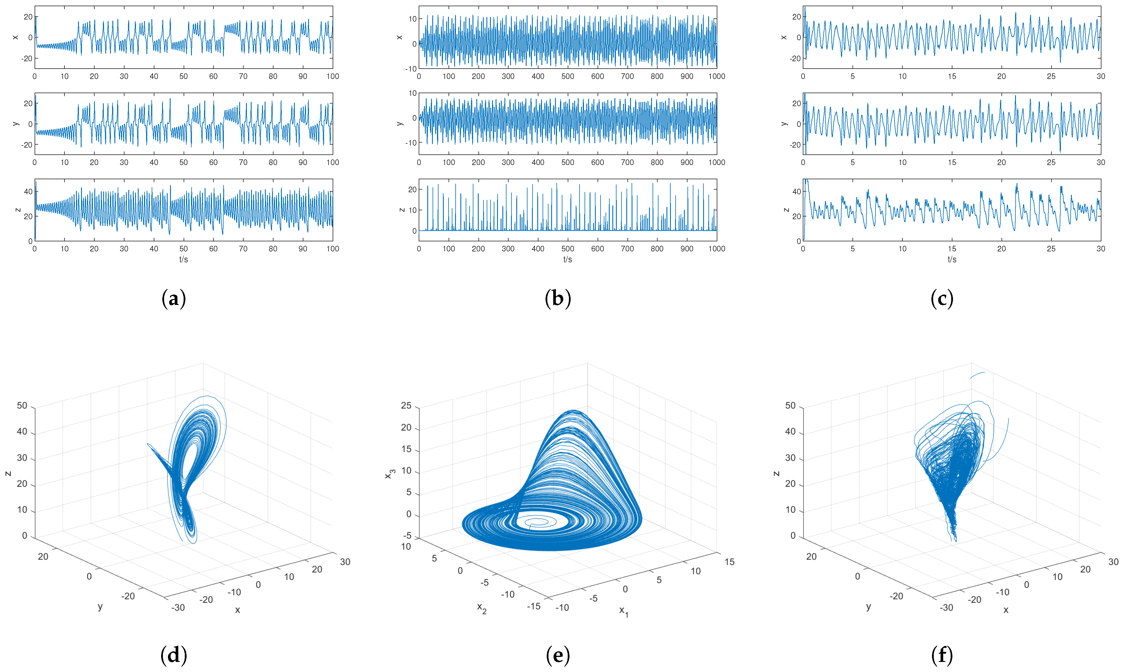
The intrinsic node dynamics across x-, y-, and z-layers are, respectively, governed by Lorenz, Rössler, and Chen systems. Initialized with ν 1 ( 0 ) = ( 0.5 , 1 , 1 ) T for the Lorenz system, Figure 2a illustrates its unstable open-loop behavior. Corresponding initializations ν 2 ( 0 ) = ( 1 , 0.5 , 2 ) T and ν 3 ( 0 ) = ( 0.5 , 1 , 1 ) T generate the unstable trajectories shown in Figure 2b,c for Rössler and Chen systems, respectively.
Figure 2. Time domain graphs and attractors: (a) Lorenz system time domain. (b) Rössler system time domain. (c) Chen system time domain. (d) Lorenz attractor. (e) Rössler attractor. (f) Chen attractor.
Initial conditions for network nodes are specified as
x - layer : { v i 0 ( 1 ) } = { ( 29.2 , 21.9 , 7 ) T , ( 14 , 2 , 0.9 ) T , ( 24 , 8 , 5 ) T , ( 10 , 16 , 9 ) T , ( 24 , 4 , 3.2 ) T } ; y - layer : { v i 0 ( 2 ) } = { ( 0.1 , 18 , 23.5 ) T , ( 9 , 6 , 8.2 ) T , ( 6 , 12 , 2 ) T , ( 26 , 9.8 , 1 ) T , ( 6 , 13 , 9.5 ) T } ; z - layer : { v i 0 ( 3 ) } = { ( 5 , 9 , 12 ) T , ( 8 , 0 , 3 ) T , ( 12 , 23 , 5 ) T , ( 16 , 24 , 9 ) T , ( 19 , 4 , 9.5 ) T } .
The intra-layer synchronization error is quantified as follows.
The fixed-time synchronization control strategy (3) is implemented with parameters derived from Theorem 1. For numerical verification, the control gain ξ i ( k ) is configured to satisfy
ξ i ( k ) γ ( k ) h λ min ( Γ 1 ) c λ min ( Γ 2 ) ,
where h = c = 0.1 . Through spectral analysis, the minimum eigenvalues of Γ 1 = Y I N G and Γ 2 = L I N Q are computed as λ min ( Γ 1 ) 6.0292 × 10 18 and λ min ( Γ 2 ) = 1.8562 , respectively. Substitution yields ξ i ( k ) 2 0.1 ( 6.0292 × 10 18 ) + 0.18562 ) 2.1856 , ensuring compliance with Theorem 2 requirements.
The theoretical convergence time is determined via
T = 2 1 Ω τ 2 τ 1 τ 2 + 1 Ω τ 4 τ 4 τ 3 ln ( 1 + Ω θ min ) ,
with parameters η min = θ min = 5 , τ 1 = 5 , τ 2 = 3 , τ 3 = 1 , τ 4 = 5 . Computational evaluation gives Ω 6.58 , resulting in T 0.2215 .
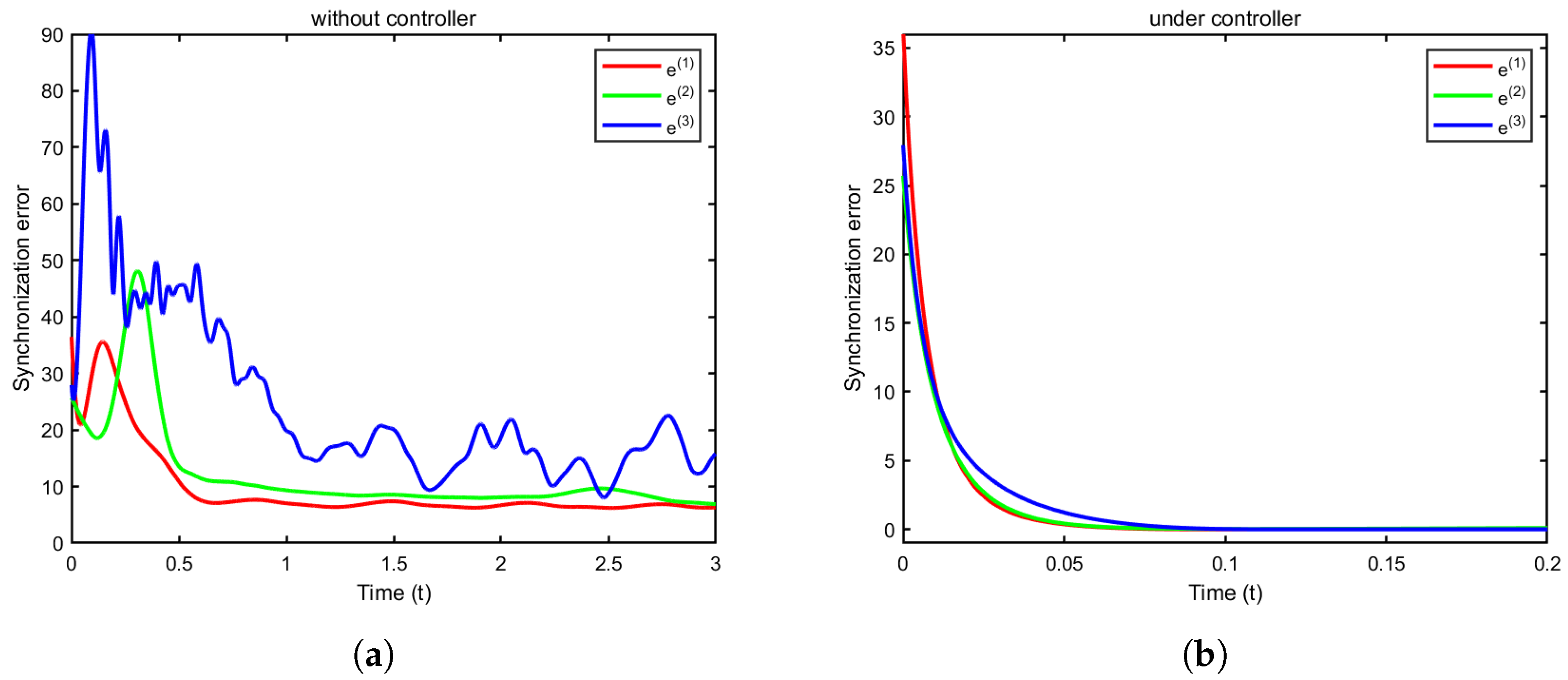
Figure 3a demonstrates the open-loop synchronization errors e ( d ) ( t ) ( d = 1 , 2 , 3 ), confirming the network’s inherent inability to achieve intra-layer synchronization. Conversely, Figure 3b displays the closed-loop error evolution under the controller (4), exhibiting asymptotic convergence within T = 0.222 , after which the error converges to below 10 3 .
Figure 3. Intra-layer synchronization error. (a) The three-layered network is under no controller. (b) The three-layered network using an FDTS controller (4).

4.2. Inter-Layer Synchronization

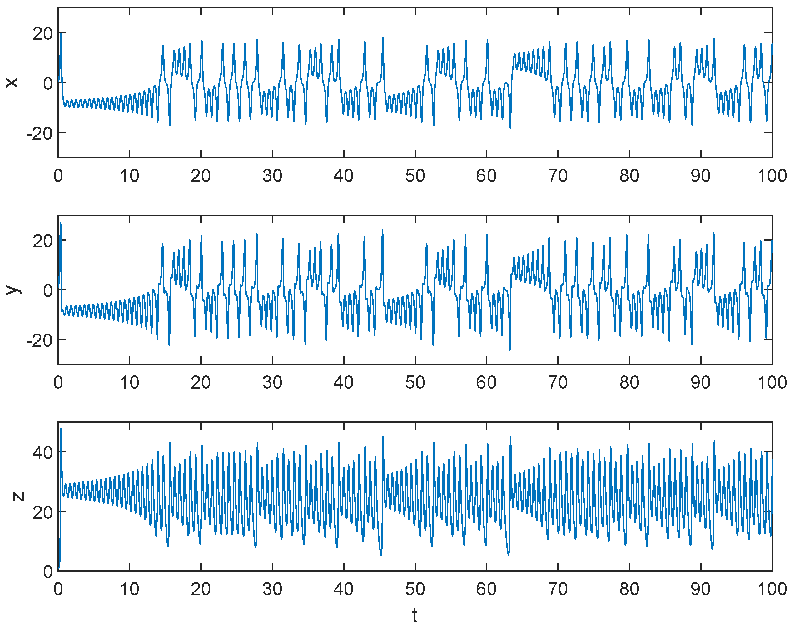
The nodal dynamics are governed by the Lorenz system with initial states consistent with Section 4.1 specifications: ν 1 ( 0 ) = ( 5 , 9 , 12 ) T , ν 2 ( 0 ) = ( 9 , 6 , 8.2 ) T , ν 3 ( 0 ) = ( 12 , 23 , 5 ) T , ν 4 ( 0 ) = ( 26 , 9.8 , 1 ) T , ν 5 ( 0 ) = ( 24 , 4 , 3.2 ) T . The temporal evolution of system (19) is demonstrated in Figure 4, exhibiting characteristic dynamic trajectories.
Figure 4. The time domain graphs of the Lorentz system. The initial value is ν ( 0 ) = ( 0.5 , 1 , 1 ) T .
To quantify the inter-layer synchronization error, we define
e i ( t ) = 1 3 3 k = 1 e i ( k ) ( t ) , i { 1 , . . . , 5 } .
The control gain selection follows:
ξ i ( k ) γ i c λ min ( Γ 2 ) ,
where λ min ( Γ 2 ) = 1.8562 is obtained through spectral analysis, thus fulfilling Theorem 2 requirements.
Through parameter configuration with
η min = 10 , θ min = 10 , τ 1 = 7 , τ 2 = 3 , τ 3 = 1 , τ 4 = 3
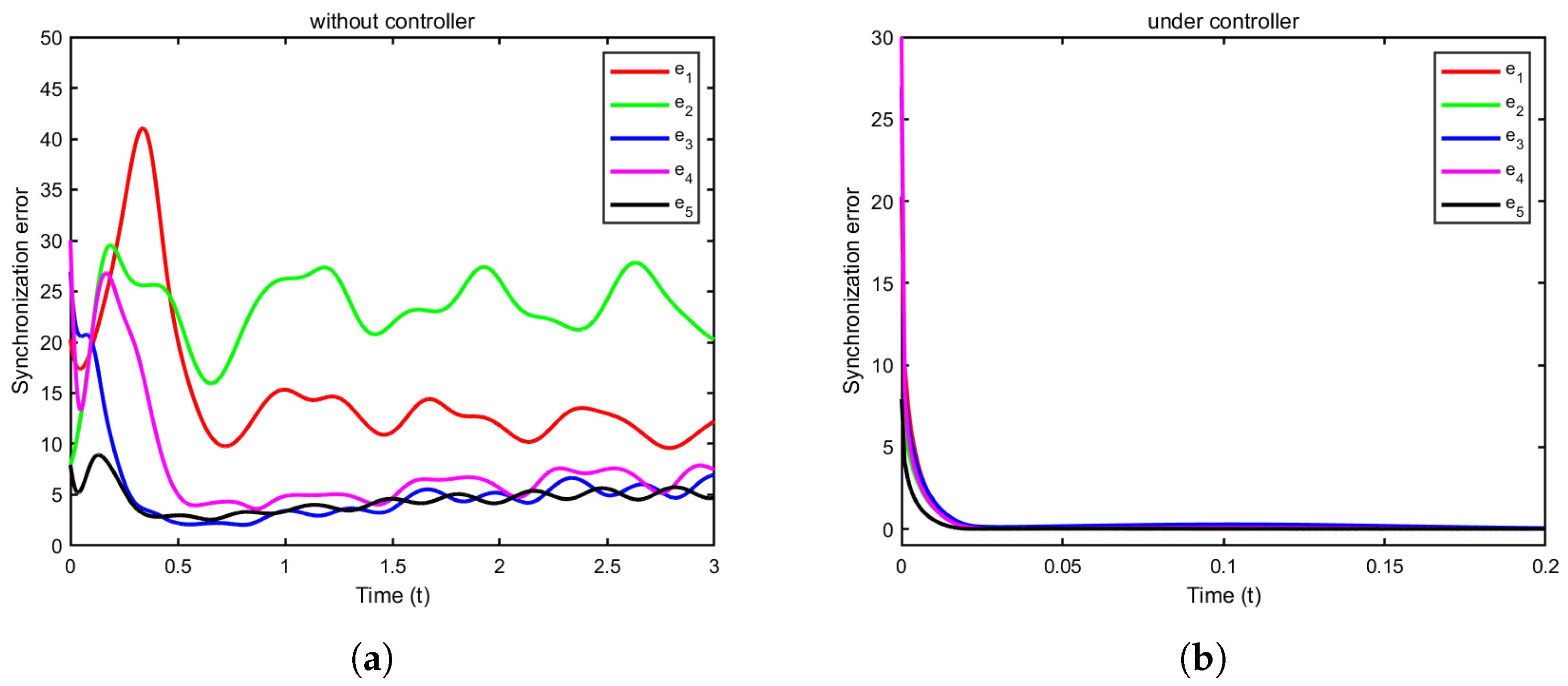
and employing uniform feedback gain γ i = 80 ( i = 1 , . . . , 5 ) in the controller (20), numerical validation confirms the system (1) achieves synchronization to (19) with convergence time T = 0.0230 , after which the error converges to below 10 3 . Figure 5a demonstrates open-loop inter-layer errors e i ( t ) ( i = 1 , . . . , 5 ), evidencing the network’s inherent synchronization incapability. Conversely, Figure 5b exhibits closed-loop error evolution under the controller (20), showing asymptotic convergence within 0.0218. Empirical evaluation reveals error attenuation rates outperforming theoretical predictions, confirming the controller’s enhanced efficacy.
Figure 5. Inter-layer synchronization error. (a) The three-layered network is under no controller. (b) The three-layered network uses an FDTS controller (20).

5. Conclusions

This study investigates synchronization phenomena in MLNs under an FDTS framework, where individual layers maintain distinct intra-layer topologies while exhibiting specific inter-layer dynamical correlations. We systematically analyze two synchronization scenarios: intra-layer synchronization within S-layer networks with autonomous nodal dynamics, and inter-layer synchronization accommodating heterogeneous dynamics across layers. The developed FDTS controllers with rigorously derived sufficient conditions enable parameter tunability for customized synchronization performance. Numerical simulations provide empirical validation of theoretical foundations. Future work will extend to MLN synchronization under partial information constraints, forming our primary research trajectory.

Author Contributions

Conceptualization, S.Y., H.H., M.-F.L., and L.Y.; methodology, S.Y., H.H., and M.-F.L.; software, S.Y.; validation, S.Y., Y.T., and L.Y.; formal analysis, S.Y., H.H., and M.-F.L.; investigation, S.Y. and Y.T.; resources, H.H. and M.-F.L.; data curation, S.Y.; writing—original draft preparation, S.Y. and H.H.; writing—review and editing, M.-F.L., Y.T., and L.Y.; visualization, S.Y.; supervision, H.H. and M.-F.L. All authors have read and agreed to the published version of the manuscript.

Funding

This research is supported by the National Natural Science Foundation of China (NSFC) (Nos. 62201102, 62003065), the Basic and Frontier Research Project of Chongqing under Grant (Nos. CSTB2024NSCQ-MSX0008), and Project of Science and Technology Research Program of Chongqing Education Commission of China (Nos. KJZD-K202400801, KJQN202200822), and the Scientific Research Project of Chongqing Technology and Business University in China (Grant No. 1956013).

Data Availability Statement

Data sharing is not applicable to this article as no new data were created or analyzed in this study.

Conflicts of Interest

The authors declare no conflicts of interest.

References

  1. Sheng, Y.; Xing, Y.; Huang, T.; Zeng, Z. Global exponential synchronization of delayed fuzzy neural networks with reaction diffusions. IEEE Trans. Fuzzy Syst. 2023, 31, 2809–2820. [Google Scholar] [CrossRef]
  2. Zheng, Z.; Zhang, Q. Synchronization in directed nonlinear complex networks under intermittent stochastic control. Commun. Nonlinear Sci. Numer. Simul. 2024, 132, 107894. [Google Scholar] [CrossRef]
  3. Liu, J.; Sun, J.P. Pinning clustering component synchronization of nonlinearly coupled complex dynamical networks. Aims Math. 2024, 9, 9311–9328. [Google Scholar] [CrossRef]
  4. Hu, X.; Wu, Y.; Ding, Q.; Xie, Y.; Ye, Z.; Jia, Y. Synchronization of scale-free neuronal network with small-world property induced by spike-timing-dependent plasticity under time delay. Phys. D Nonlinear Phenom. 2024, 460, 134091. [Google Scholar] [CrossRef]
  5. Presigny, C.; De Vico Fallani, F. Colloquium: Multiscale modeling of brain network organization. Rev. Mod. Phys. 2022, 94, 031002. [Google Scholar] [CrossRef]
  6. Shen, Q.; Liu, Y. Public opinion simulation research based on multilayer synchronization network. Syst. Eng. Theory Pract. 2017, 39, 182–190. [Google Scholar]
  7. Yang, L.; Jiang, J.; Liu, X.J. The role of interconnection patterns on synchronizability of duplex oscillatory power network. Commun. Nonlinear Sci. Numer. Simul. 2021, 93, 105507. [Google Scholar] [CrossRef]
  8. Prathiba Prathiba, S.B.; Krishnamoorthy, S.R.; Kannan, K.S.; Selvaraj, A.K.; Ranganayakulu, D.; Fang, K.; Gadekallu, T.R. Digital Twin-Enabled Real-Time Optimization System for Traffic and Power Grid Management in 6G-Driven Smart Cities. IEEE Internet Things J. 2025, 12, 29164–29175. [Google Scholar] [CrossRef]
  9. Funk, S.; Jansen, V.A.A. Interacting epidemics on overlay networks. Phys. Rev. E—Stat. Nonlinear Soft Matter Phys. 2010, 81, 036118. [Google Scholar] [CrossRef] [PubMed]
  10. Wu, X.; Li, Q.; Liu, C.; Liu, J.; Xie, C. Synchronization in duplex networks of coupled Rössler oscillators with different inner-coupling matrices. Neurocomputing 2020, 408, 31–41. [Google Scholar] [CrossRef]
  11. Shafiei, M.; Jafari, S.; Parastesh, F.; Parastesh, F.; Ozer, M.; Kapitaniak, T.; Perc, M. Time delayed chemical synapses and synchronization in multilayer neuronal networks with ephaptic inter-layer coupling. Commun. Nonlinear Sci. Numer. Simul. 2020, 84, 105175. [Google Scholar] [CrossRef]
  12. Wang, Z.; Jin, X.; Pan, L.; Feng, Y.; Cao, J. Quasi-synchronization of delayed stochastic multiplex networks via impulsive pinning control. IEEE Trans. Syst. Man Cybern. Syst. 2021, 52, 5389–5397. [Google Scholar] [CrossRef]
  13. Gadekallu, T.R.; Dev, K.; Khowaja, S.A.; Wang, W.; Feng, H.; Fang, K.; Wang, W. Responsible AI: A Comprehensive Framework, Standards, Applications and Best Practices. arXiv 2025, arXiv:2504.13799. [Google Scholar]
  14. Tang, L.; Wu, X.; Lü, J.; Lu, J.; D’Souza, R.M. Master stability functions for complete, intralayer, and interlayer synchronization in multiplex networks of coupled Rössler oscillators. Phys. Rev. E 2019, 99, 012304. [Google Scholar] [CrossRef]
  15. Xu, Y.; Wu, X.; Mao, B.; Lü, J.; Xie, C. Finite-time intra-layer and inter-layer quasi-synchronization of two-layer multi-weighted networks. IEEE Trans. Circuits Syst. I Regul. Pap. 2021, 68, 1589–1598. [Google Scholar] [CrossRef]
  16. Ning, D.; Wu, X.; Feng, H.; Chen, Y.; Lu, J. Inter-layer generalized synchronization of two-layer impulsively-coupled networks. Commun. Nonlinear Sci. Numer. Simul. 2019, 79, 104947. [Google Scholar] [CrossRef]
  17. Liu, H.; Li, J.; Li, Z.; Zeng, Z.; Lu, J. Intralayer synchronization of multiplex dynamical networks via pinning impulsive control. IEEE Trans. Cybern. 2020, 52, 2110–2122. [Google Scholar] [CrossRef]
  18. Ning, D.; Fan, Z.; Wu, X.; Han, X. Interlayer synchronization of duplex time-delay network with delayed pinning impulses. Neurocomputing 2021, 452, 127–136. [Google Scholar] [CrossRef]
  19. Jin, X.; Wang, Z.; Yang, H.; Song, Q. Synchronization of multiplex networks with stochastic perturbations via pinning adaptive control. J. Frankl. Inst. 2021, 358, 3994–4012. [Google Scholar] [CrossRef]
  20. Sun, S.; Ren, T.; Xu, Y. Pinning synchronization control for stochastic multi-layer networks with coupling disturbance. ISA Trans. 2022, 128, 450–459. [Google Scholar] [CrossRef]
  21. Haimo, V.T. Finite time controllers. SIAM J. Control Optim. 1986, 24, 760–770. [Google Scholar] [CrossRef]
  22. Polyakov, A. Nonlinear feedback design for fixed-time stabilization of linear control systems. IEEE Trans. Autom. Control 2011, 57, 2106–2110. [Google Scholar] [CrossRef]
  23. Shi, J.; Zhou, P.; Jia, Q.; Cai, S. Fixed-time synchronization of multilayered complex dynamic networks via quantized variable-gain saturated control. Inf. Sci. 2024, 681, 121206. [Google Scholar] [CrossRef]
  24. Xiong, K.; Hu, C. Fixed-time output synchronization of multilayered coupled networks with quaternion: An exponential quantized scheme. Neurocomputing 2025, 613, 128742. [Google Scholar] [CrossRef]
  25. Yu, G.N.; Liu, X.K.; Lei, Y.; Wang, Y.W. Fixed-time synchronization in pth moment for stochastic multi-layer neural networks: An adaptive graph-theoretic Lyapunov functional approach. Neurocomputing 2025, 636, 130002. [Google Scholar] [CrossRef]
  26. Wang, X.; Cao, J.; Wang, J.; Qi, J. A novel fast fixed-time control strategy and its application to fixed-time synchronization control of delayed neural networks. Neural Process. Lett. 2022, 54, 145–164. [Google Scholar] [CrossRef]
  27. Wang, X.; Cao, J.; Yang, B.; Chen, F. Fast fixed-time synchronization control analysis for a class of coupled delayed Cohen-Grossberg neural networks. J. Frankl. Inst. 2022, 359, 1612–1639. [Google Scholar] [CrossRef]
  28. Ni, J.; Liu, L.; Liu, C.; Hu, X.; Li, S. Fast fixed-time nonsingular terminal sliding mode control and its application to chaos suppression in power system. IEEE Trans. Circuits Syst. II Express Briefs 2016, 64, 151–155. [Google Scholar] [CrossRef]
  29. Tang, S.; Li, J.; Jiang, H.; Wang, J. Fixed-Time Aperiodic Intermittent Control for Quasi-Bipartite Synchronization of Competitive Neural Networks. Entropy 2024, 26, 199. [Google Scholar] [CrossRef]
  30. Wang, Q.; Zhao, H.; Liu, A.; Niu, S.; Gao, X.; Zong, X. An improved fixed-time stability theorem and its application to the synchronization of stochastic impulsive neural networks. Neural Process. Lett. 2023, 55, 7447–7467. [Google Scholar] [CrossRef]
  31. Chen, G.; Ueta, T. Yet another chaotic attractor. Int. J. Bifurc. Chaos 1999, 9, 1465–1466. [Google Scholar] [CrossRef]
  32. DeLellis, P.; di Bernardo, M.; Russo, G. On QUAD, Lipschitz, and contracting vector fields for consensus and synchronization of networks. IEEE Trans. Circuits Syst. I Regul. Pap. 2010, 58, 576–583. [Google Scholar] [CrossRef]
  33. Huang, X.; Dong, Z.; Zhang, F.; Zhang, L. Model-free adaptive integral sliding mode constrained control with modified prescribed performance. IET Control Theory Appl. 2023, 17, 1044–1060. [Google Scholar] [CrossRef]
  34. Mitrinovic, D.S.; Pecaric, J.; Fink, A.M. Classical and New Inequalities in Analysis; Springer Science & Business Media: Berlin/Heidelberg, Germany, 2013. [Google Scholar]
  35. Yang, S.; Zhang, W.; Ruan, D.; Yang, T.; Li, Y. Fast fixed-time impulsive bipartite synchronization of TS fuzzy complex networks with signed graphs. Nonlinear Anal. Hybrid Syst. 2023, 48, 101325. [Google Scholar] [CrossRef]
  36. Bhat, S.P.; Bernstein, D.S. Continuous finite-time stabilization of the translational and rotational double integrators. IEEE Trans. Autom. Control 1998, 43, 678–682. [Google Scholar] [CrossRef]
  37. Zhang, C.; Zhang, C.; Zhang, X.; Wang, F.; Liang, Y. Dynamic event-triggered control for intra/inter-layer synchronization in multi-layer networks. Commun. Nonlinear Sci. Numer. Simul. 2023, 119, 107124. [Google Scholar] [CrossRef]
  38. Lü, J.; Chen, G.; Cheng, D.; Celikovský, S. Bridge the gap between the Lorenz system and the Chen system. Int. J. Bifurc. Chaos 2002, 12, 2917–2926. [Google Scholar] [CrossRef]
Disclaimer/Publisher’s Note: The statements, opinions and data contained in all publications are solely those of the individual author(s) and contributor(s) and not of MDPI and/or the editor(s). MDPI and/or the editor(s) disclaim responsibility for any injury to people or property resulting from any ideas, methods, instructions or products referred to in the content.

Article Metrics

Citations

Article Access Statistics

Multiple requests from the same IP address are counted as one view.