Abstract
The dynamic migration of mineral particles within spiral separators and its control via structural parameters are not yet fully understood, hindering efficiency improvements. To this end, a set of spiral separators with systematically adjusted structural parameters was designed. Extensive sampling of a 1–0.25 mm coal slurry yielded 120 samples from 6 separators, across 5 turns and 4 radial streams. Sink-float analysis revealed a well-defined three-stage separation mechanism: the roughing stage involves rapid segregation of light and heavy particles, while intermediate-density particles remain widely distributed; the intensified cleaning stage governs the radial migration of intermediate-density particles while simultaneously enriching the high-density and low-density fractions; and the final cleaning stage stabilizes the particle distribution and redirects misplaced particles. The influence of key structural parameters was also quantified: the composite cross-section outperformed cubic parabolic and elliptical profiles, markedly enhancing the separation of high-density and medium-high-density particles from the lighter product; increasing the trough inclination angle significantly promoted the radial inward migration of medium-high-density particles; a reduced pitch-to-diameter ratio effectively concentrated high-density and medium-high-density particles within inner and middle regions. Based on these insights, a “process intensification” strategy was proposed and materialized in a novel spiral separator design featuring stage-optimized, multi-parameter coordination. Performance evaluation demonstrated a separation efficiency of 94.74% under equivalent product quality constraints, a substantial improvement over conventional design. This work provides a fundamental, stage-specific understanding of particle separation dynamics and establishes a practical basis for the advanced design of high-efficiency spiral separation systems.
1. Introduction
Spiral separators, or spiral concentrators, are widely employed in mineral beneficiation for their simplicity and high separation efficiency, particularly in processing of iron ore, coastal placers, and fine coal [1,2,3,4,5,6]. Their application has been further expanded to solid waste processing, such as treating fine smelting slag and gasification wastes, where they preconcentrate valuable minerals or remove gangue materials [7,8]. This broadening application scope underscores the necessity for design improvements, which are contingent upon a thorough understanding of particle dynamics during separation. Consequently, elucidating particle transport mechanisms within spiral separators has emerged as a critical research focus and a persistent challenge in the field.
Current knowledge of particle motion in spiral separators is predominantly derived from experimental analyses that examine the distribution of macroscopic indicators (e.g., yield, grade, ash content) and correlate these with flow field characteristics and force analysis to elucidate the underlying motion behavior [9,10,11,12]. These studies have successfully established macroscopic patterns of particle stratification and segregation by density and size differences. Additionally, numerical simulation has also been employed to gain deeper insights into the theory of spiral separation. Researchers such as Sudikondala et al. [13,14] and Ye et al. [15] applied coupled VOF and RANS turbulence models to analyze the flow field and particle distribution. Similarly, Mahran et al. [16,17] examined particle flow using CFD methods, and Meng et al. [18,19] employed an Eulerian multi-fluid VOF model to study the flowing film profile and particle stratification. However, a common limitation among these studies is their focus on steady-state conditions, which effectively explains final separation outcomes but fails to capture the transient dynamics and evolution of particle motion throughout the actual process. This gap is significant because the spiral separation process is inherently a continuous, dynamic system comprising multiple helical turns connected in series.
In recent years, there has been growing recognition of the importance of dynamic characteristics, leading to exploratory studies. For example, Boucher et al. [20,21] innovatively employed Positron Emission Particle Tracking (PEPT) to trace the motion trajectories of individual hematite and quartz particles within the spiral trough, providing valuable experimental insights into particle behavior. However, the PEPT technology is limited to tracking a small number of radiolabeled particles, which restricts its ability to represent collective particle behavior at industrially relevant concentrations. In numerical simulation, Liu Penghui et al. [22] pioneered the application of a coupled CFD-DEM approach, explicitly categorizing the separation process into roughing, transition, and quasi-steady stages to reveal dynamic evolution. Meng et al. [23] investigated the effect of feed flow rate on the flow field and mineral distribution in the first turn, confirming the decisive influence of roughing flow field development on separation outcomes. Other scholars, such as Huang Bo et al. [24], Liu Huizhong [25] and Gao Shuling [26], have further explored dynamic changes in the flowing film and particle migration, examining factors such as feed flow rate effects and pitch-to-diameter ratio optimization. Despite providing a powerful tool for investigating particle motion, existing numerical models possess notable shortcomings. They often incorporate significant simplifications of the actual separation environment and are typically validated under conditions of low pulp density [14,17,27]. When applied to industrial-scale scenarios—characterized by high feed solid concentrations (sometimes exceeding 40%) and multi-turn structures (typically five or more turns)—achieving high-fidelity, full-process modeling of the immense number of particles presents a formidable computational challenge. Given this situation, adopting systematic, industrial-scale experiments to deconstruct the internal mechanisms has emerged as a necessary and effective research pathway.
Structural parameters, such as the pitch-to-diameter ratio [26,28,29], trough inclination angle [30,31], cross-sectional geometry [32,33,34,35,36], or wall roughness [37,38], are critical factors governing separation performance. Current research primarily focuses on assessing the influence of individual structural parameters on the properties of the final separation products, confirming their significant role in regulating concentrate yield and grade. Since a spiral separator consists of multiple connected helical turns, a key unanswered question is how these parameters distinctly regulate separation dynamics of the multi-turn process. Addressing this gap is vital for targeted optimization of spiral designs to achieve specific beneficiation objectives.
To bridge these research gaps, this study systematically investigates the spiral separation process to elucidate the dynamic influence of key structural parameters. The experimental campaign utilized custom-designed, small-scale industrial spiral separators (650 mm in diameter) with six distinct structural configurations. A comprehensive sampling strategy was implemented, collecting pulp samples from every turn across all spirals, culminating in a total of 120 samples. These samples were analyzed to delineate the evolution of product yield, ash content, and the radial distribution of particles across different density fractions during the spiral separation process. Subsequently, the mechanisms through which critical structural parameters—specifically cross-sectional profile, trough inclination angle, and pitch-to-diameter ratio—govern particle distribution patterns at different stages were elucidated. Furthermore, leveraging this staged-process understanding, a novel design concept for a composite-configuration spiral separator is proposed. By employing systematic experimentation at an industrially relevant scale, this study yields conclusions of direct engineering significance, providing valuable insights for the optimized design and operational control of spiral separators.
2. Materials and Methods
2.1. Experimental Materials
The raw coal sample was collected from the underflow of the coal slime classifying cyclones at the Fangezhuang Coal Preparation Plant (Tangshan, China). The coal sample was air-dried and subsequently wet-sieved using a vibrating screen to isolate the 1–0.25 mm size fraction. Standard laboratory testing was completed by screening and sink-float experiments, with the complete characterization data presented in Table 1. As indicated in the table, the 0.50–0.25 mm fraction represents the dominant size class, accounting for 49.80% of the total sample. A clear correlation was observed between particle size and ash content, wherein finer particles exhibited higher ash values. Density distribution analysis indicated that the intermediate density fraction (1.4–1.8 g/cm3) constituted a relatively small portion (22.20%), while the low-density (<1.4 g/cm3) and high-density (>1.8 g/cm3) fractions were predominant, accounting for 38.08% and 39.73% of the sample, respectively. Furthermore, the ash content demonstrated a consistent increasing trend with rising particle density. The coarse coal slime sample was ground to a particle size of less than 0.1 mm and subjected to elemental analysis. The results of the elemental analysis for the test coal sample are presented in Table 2.

Table 1.
Particle size and density distribution of raw coal.
Table 2.
Ultimate analysis of coal sample.
The novel spiral separator designed in this work features intentionally modified structural profiles along its spiral turns. To enable direct visualization of particle motion, a composite feed was prepared by replacing corresponding density fractions in the raw coal with distinctly colored tracer particles. Part of these tracers were fabricated from PVC compounds with densities adjusted to match key density fractions of the coal sample, as specified in Table 3.
Table 3.
Physical properties and color codes of the tracer particles.
2.2. Experimental System and Methodology
A schematic diagram of the experimental setup employed for the spiral separation tests is presented in Figure 1a. The primary components include a spiral trough (B) mounted on a stainless-steel frame (H), a feed pipe (O) connected to the inlet (A), a sample collection launder (C), an agitation tank (K), a progressing cavity pump (J), and a variable-frequency drive (F). In each experiment, the coal sample and water were mixed in the agitation tank (K) to prepare a slurry at a predetermined solid concentration. The slurry was then pumped from the bottom of the tank using the progressing cavity pump (J), which was powered by the variable-frequency control box (E) to maintain a stable flow rate. A portion of the slurry was recirculated to the agitation tank via a return pipe (M), while the remaining stream was fed into the spiral separator. At the base of the spiral trough, a diversion splitter directed the separated products back to the agitation tank, establishing a closed-circuit flow. Prior to formal product sampling, the system was operated in full recirculation mode for 3 min to ensure full stabilization of the flow.
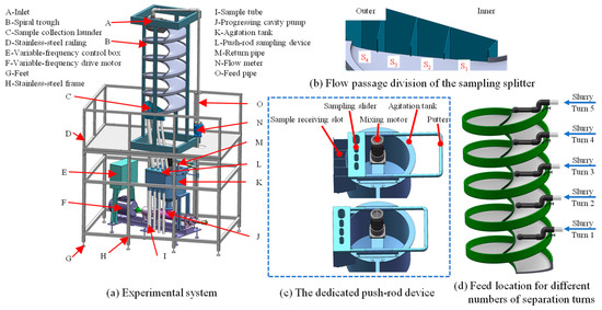
Figure 1.
The experimental system for spiral separation tests.
An external sampling splitter, shown schematically in Figure 1b, was installed at the base of the spiral to divide the slurry into four discrete streams along the radial direction of the trough. These streams, from the inner to the outer, were designated as S1, S2, S3, and S4, respectively. A purpose-built push-rod assembly, directly connected to the splitter and depicted in Figure 1c, was integrated to enable dual-mode operation: closed-loop circulation and sample collection. During operation, the push-rod assembly directs the slurry flow by switching between two predefined positions. For closed-loop circulation, the rod is fully retracted, directing all slurry streams back into the agitation tank. For sample collection, the rod is fully advanced, channeling all four streams into individual collection buckets for a precise period of 4 s. The 4-s sampling duration was determined through preliminary tests to ensure sufficient sample mass for subsequent analysis while minimizing disturbance to the steady-state flow. Subsequently, the collected slurry streams were processed by vacuum filtration and drying to prepare analytical samples.
A movable external feed delivery device was designed to investigate the separation dynamics and particle distribution behavior across different turns of the spiral. This device, equipped with slotted apertures and threaded knobs, allows for secure and adjustable mounting onto the exterior sidewall of the spiral trough. As shown in Figure 1c, the vertical height of this device is adjustable, thereby providing precise control over the number of separation turns experienced by the particles. For example, in a spiral separator with five turns, positioning the feed device at the topmost location allows particles to undergo a full five-turn separation. Lowering the device by one turn correspondingly reduces the effective number of separation turns by one.
2.3. Data Processing
Separation tests were performed using six custom-manufactured spiral separators (manufactured by Qinyang Qinlong Chemical Antiseptic Co., Ltd., Qinyang, China) with distinct structural configurations, designed to systematically evaluate the effects of specific structural variations on particle distribution behavior. The key structural parameters are schematically illustrated in Figure 2. As shown in Figure 2a, the pitch, which determines the longitudinal inclination angle (α), is conventionally represented by the pitch-to-diameter ratio (P/D). A cross-sectional view is presented in Figure 2b (taking one profile as an example), where the transverse inclination angle φ(r) is defined as the angle between the tangent to the cross-sectional profile at any radial position r and the horizontal, whereas the trough inclination angle (β) is defined as the angle between line AB and the horizontal. The trough surfaces of spiral separators are typically designed in cubic parabolic or elliptical profiles. As schematically illustrated in Figure 2b, the red curve represents the cubic parabolic profile, while the blue curve represents the elliptical profile. It can be observed that the two curves intersect at point C. Based on this intersection, a novel composite profile was designed, in which segment AC adopts the cubic parabolic shape (red section) and segment CB adopts the elliptical shape (blue section). Generally, for minerals with small density differences, the suitable range for the trough inclination angle of spiral separators is 9°–17°, and the suitable range for the pitch-to-diameter ratio is 0.34–0.45. In this study, six spiral separators with distinct structural parameters were designed to investigate the influence of key parameters—cross-sectional profile, trough inclination angle, and pitch-to-diameter ratio. The complete technical specifications of all six spiral separators are provided in Table 4.
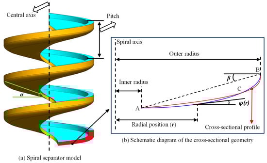
Figure 2.
Schematic diagram of structural parameters for the spiral separator.
Table 4.
The comprehensive technical specifications of spiral separators.
For each separator, four samples were collected at each spiral turn using the sampling device described earlier, resulting in a total of 120 solid samples for subsequent processing. The solids collected from each sample bucket were first dewatered using a disc vacuum filter, thoroughly dried in a vacuum oven, and then precisely weighed on an electronic balance to determine their individual masses for subsequent yield calculation. Each dried sample then underwent coning and quartering—a standardized sample reduction technique. This procedure involved heaping the material into a conical pile, flattening it into a uniform disc, and dividing it into four quadrants using a cross-shaped cutter. Two diagonally opposite quarters were combined and homogenized, and this process was repeated iteratively until the target mass of the representative subsample was attained. For ash content determination, the reduced subsamples were evenly distributed in porcelain boats and ashed in a muffle furnace. For density distribution analysis, the subsamples were transferred to centrifuge bottles and subjected to laboratory-scale float-sink testing. A graded series of organic heavy liquids, with densities ranging sequentially from 1.3 to 1.8 g/cm3, was employed for this purpose.
Following the experimental procedures, the yield and mass distribution proportions were calculated from the acquired data and subsequently visualized using graphs plotted with MATLAB (v2022).
- ➢
- Yield calculation
The solid yield for a given sampling stream j at spiral turn i was quantified using Equation (1):
where:
i denotes the turn index (1–5, representing turns 1 to 5);
indicates the stream number (1–4, corresponding to streams 1 to 4);
is the mass of the product collected in stream j at turn i;
represents the yield for stream j at turn i.
- ➢
- Mass distribution calculation
The mass distribution of a specific density fraction k from stream j at turn i was calculated using Equation (2):
where:
k denotes the density fraction index (1–4), with each index corresponding to a specific particle type as follows:
k = 1: Low-density (<1.4 g/cm3) particles;
k = 2: Medium-low-density (1.4–1.6 g/cm3) particles;
k = 3: Medium-high-density (1.6–1.8 g/cm3) particles;
k = 4: High-density (>1.8 g/cm3) particles.
represents the product mass of density fraction k at turn i, stream j;
indicates the mass distribution proportion of density fraction k at turn i, stream j.
3. Results and Discussion
3.1. Reproducibility and System Consistency Verification
To verify the consistency of the experimental system, Spiral #1 was subjected to triplicate tests at a mass concentration of 25% and a flow rate of 2.0 m3/h. The results are summarized in Table 5. The analysis indicates that the maximum error in yield across the three tests was 3.08%, and the maximum error in ash content was 2.53%. These results confirm the reproducibility of the experiments within the designed system. It should be noted that all subsequent experiments were conducted under the same conditions of 25% mass concentration and a flow rate of 2.0 m3/h.
Table 5.
Results of the triplicate tests for Spiral #1 (mass concentration: 25%; flow rate: 2.0 m3/h).
3.2. Deconstruction of the Separation Process
3.2.1. Ash Content, Yield and Particle Distribution During the Spiral Separation Process
Figure 3 presents the evolution of ash content and solid yield across the radial sampling streams with increasing spiral turns, with the data points representing the average results from all six separators at the completion of each turn. As revealed in Figure 3a, a pronounced radial heterogeneity in ash content was established after just one single separation turn, decreasing from 70% in the innermost stream (S1) to 10% in the outermost stream (S4). With further turns, the ash content of S1 demonstrated a gradual increase from 70% to 78%. In contrast, the ash content in S4 remained largely stable, exhibiting only a marginal decreasing trend. Conversely, streams S2 and S3 exhibited considerable ash content variations, both decreasing from 27% to 18% and from 60% to 52%, respectively.
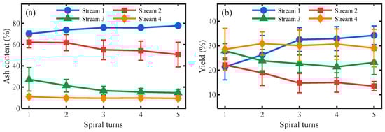
Figure 3.
Trends of ash content (a) and yield (b) with increasing spiral turns.
Figure 3b illustrates the distinct evolutionary trends in solid yield across the radial sampling streams throughout the separation process. Following the first turn, the yield distribution was relatively concentrated, with values spanning a narrow range of 20–30% across all four streams (S1 to S4). As separation progressed, the yield of S1 increased gradually, though the rate of increase moderated after the third turn. In contrast, the yield of S4, while subject to minor fluctuations, exhibited an overall declining tendency. Similarly, streams S2 and S3 displayed comparable trends, with their yield gradually decreasing as the number of turns increased—a process characterized by a decelerating rate of decline beyond the third turn.
To gain deeper insights into particle migration dynamics, Figure 4 shows the evolution of the mass distribution of different density fractions as the number of spiral turns increased, with the data points representing the average results from all six separators at the completion of each turn. As seen in Figure 4a, high-density particles were primarily concentrated in stream S1, with their mass distribution decreasing progressively across the radial direction toward the outer streams, leaving only negligible quantities in the outermost stream S4. As separation progressed, the mass distribution of high-density particles in S1 increased substantially. Conversely, a continuous decline was observed in streams S2, S3, and S4. Owing to the initially low mass distribution of high-density particles in S4, the subsequent reduction was less pronounced with additional turns. In contrast, the declines observed in S2 and S3 were more substantial. Specifically, in S3, the mass distribution of high-density particles declined to a minimal level after the third turn, with no significant reduction thereafter. In S2, however, the rate of decline diminished significantly after the third turn.
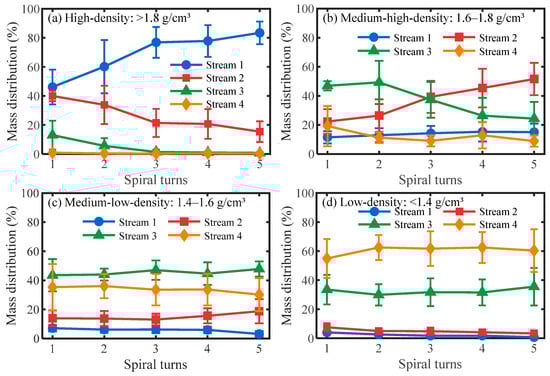
Figure 4.
Variation in mass distribution of different density fractions with increasing spiral turns.
As presented in Figure 4b, streams S2 and S3 served as the primary accumulation zones for medium-high-density particles. The dominant zone shifted from S3 to S2 after the third spiral turn. As separation progressed, the mass distribution of medium-high-density particles exhibited an increasing trend in both S1 and S2, with the latter demonstrating a more substantial increase. In contrast, the mass distribution in S3 and S4 decreased with additional turns, with a more marked reduction observed in S3. After three turns, the mass distribution of medium-high-density particles in S1 and S4 stabilized, suggesting that an equilibrium state was approached in these streams. In contrast, streams S2 and S3 continued to undergo significant dynamic changes.
As shown in Figure 4c, medium-low-density particles were primarily concentrated in streams S3 and S4. Throughout the separation process, the relative mass distribution of these particles across the streams maintained a consistent ranking: S3 > S4 > S2 > S1. The mass distribution of medium-low-density particles exhibited distinct evolutionary trends across the streams: a slight decrease in S1 and S4, minimal variation in S3, and a pronounced increase in S2 as separation progressed. Beyond three spiral turns, the mass distribution stabilized in S1 and S4, indicating the attainment of a steady state, whereas it continued to evolve dynamically in S2 and S3.
As demonstrated in Figure 4d, low-density particles were primarily concentrated in streams S3 and S4. Throughout the separation process, their mass distribution consistently adhered to the sequence S4 > S3 > S2 > S1. A notable distribution shift occurred at the second spiral turn: the mass distribution of low-density particles increased substantially in S4, while it decreased significantly across S1 to S3. Beyond this point, further spiral turns had negligible influence on the distribution of low-density particles.
3.2.2. Particle Distribution Characteristics at 1st, 3rd, and 5th Spiral Turns
Based on the preceding analysis of Figure 3 and Figure 4, three key positions—corresponding to the completion of the 1st, 3rd, and 5th spiral turns—were identified. The radial distribution characteristics of particles at these three positions are further illustrated in Figure 5, with the data points representing the average values from the six separators. As shown in Figure 5a, after the first separation turn, high-density particles were predominantly concentrated in S1, accounting for 45% of the mass distribution. Substantial proportions were also observed in S2 (40%) and S3 (18%). Medium-high-density particles form a distribution peak in S3, constituting approximately 45% of the total. Medium-low-density particles showed a relatively uniform distribution overall, with slightly higher proportions in S3 and S4. Low-density particles were strongly concentrated in S4, with their mass distribution in S4 accounting for 55%, whereas this ratio in S1 was only about 5%.
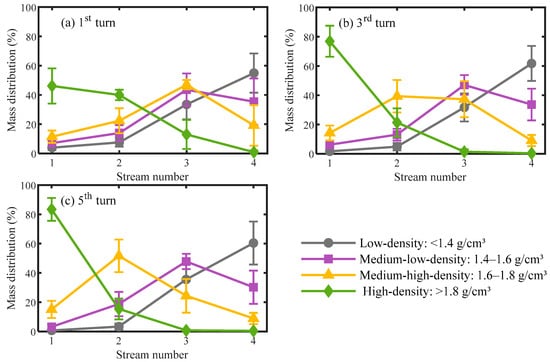
Figure 5.
Radial distribution characteristics of particles at three key spiral turns.
As shown in Figure 5b, after two additional turns of separation, the mass distribution of high-density particles in S1 increased markedly to approximately 80%. In contrast, their proportion in S2 reduced substantially, while S3 and S4 contained negligible amounts of these particles. Concurrently, medium-high-density particles exhibited comparable mass distribution in S2 and S3, each accounting for approximately 40%. In S1 and S4, however, the corresponding proportions were considerably lower, at 18% and 14%, respectively. Medium-low-density particles were predominantly concentrated in streams S3 and S4, with respective mass distributions of 42% and 37%. Furthermore, the enrichment of low-density particles in the outermost stream (S4) became more pronounced, reaching approximately 60%, in contrast to merely 5% in S1.
As illustrated in Figure 5c, following five separation turns, the innermost stream (S1) was highly enriched with high-density particles, which accounted for 85% of its total mass distribution. In comparison, the mass distribution of high-density particles in S2 was only about 15%, while virtually none were detected in S3 and S4. For medium-high-density particles, S2 was the primary aggregation location, with mass distribution accounting for 50%. In addition, their mass distribution in S3 and S4 was relatively high, at 23% and 10%, respectively. Medium-low-density particles were chiefly concentrated in S3, exhibiting a mass distribution of 42%. Substantial proportions were likewise present in S2 (20%) and S4 (35%). Meanwhile, the outermost stream (S4) contained the highest concentration of low-density particles, constituting nearly 60% of the mass distribution.
3.2.3. Stage Characteristics and Mechanism Explanation of the Separation Process
Based on a comprehensively analysis of the experimental results presented in Figure 3, Figure 4 and Figure 5, the spiral separation process of coarse coal slime (1–0.25 mm) can be deconstructed into three sequential and functionally distinct stages according to its dynamic evolution characteristics: the Roughing Stage (1st turn), the Intensified Cleaning Stage (2nd–3rd turns), and the Final Cleaning Stage (4th–5th turns). The characteristics of each stage and their underlying dominant mechanisms are elaborated as follows:
- (1)
- Roughing Stage (1st turn): Rapid stratification and light/heavy particle separation
Upon entering the spiral trough, particles undergo rapid separation between light and heavy fractions. High-density particles (>1.8 g/cm3) become significantly enriched in the innermost stream (S1, mass distribution ~45%), while low-density particles (<1.4 g/cm3) are quickly transported to the outermost stream (S4, mass distribution ~55%). In contrast, intermediate-density particles (1.4–1.8 g/cm3) exhibit a relatively broad distribution without forming distinct enrichment zones. This distribution pattern directly results in a pronounced radial ash gradient, decreasing sharply from ~70% in S1 to ~10% in S4.
The essence of this phenomenon lies in the high feed slurry velocity and the absence of a well-developed radial circulating flow upon entry into the spiral trough. During this stage, the pulp undergoes a rapid transition from inertia-dominated to spiral flow. Entering the trough with high initial kinetic energy, the slurry trajectory is initially governed by inertia, impacting the outer wall in an approximately straight line [22,25]. After deflection by the wall, the flow direction is gradually constrained to follow the spiral path downwards, and a radial secondary flow begins to develop, although it remains unstable in this nascent phase. Within this dynamic flow field, particles of different densities exhibit distinct migration behaviors due to differences in force mechanisms: High-density particles, owing to their significant density difference, effectively penetrate the flow film and settle onto the trough bottom. Once settled, the component of gravity along the inclined trough bottom becomes the dominant force, driving them to overcome fluid drag and slide continuously towards the inner region (S1). Conversely, low-density particles are confined to the upper high-velocity flow layer, dominated by centrifugal force, and are rapidly transported to the outer region (S4). For intermediate-density particles, the flow field conditions at this stage are unfavorable for precise separation. Due to intense pulp turbulence and the insufficient establishment of a stable secondary flow, these particles lack a sustained, directional radial driving force for separation. Consequently, they are primarily carried by the pulp, resulting in a broad and relatively uniform radial distribution.
- (2)
- Intensified Cleaning Stage (2nd–3rd turns): Dynamic migration and precise separation of intermediate particles
This stage is crucial for determining the final separation efficiency. The particle distribution profile becomes noticeably “narrower” and “sharper” compared to the first turn. The enrichment of high-density particles in S1 increases substantially to approximately 80%, and the concentration of low-density particles in S4 consolidates to around 60%. The most critical feature is the intense redistribution of intermediate-density particles: medium-high-density particles (1.6–1.8 g/cm3) show a clear inward migration trend, with their distribution gravity shifting from S3 to S2, while medium-low-density particles (1.4–1.6 g/cm3) migrate outward (to S3 and S4). This dynamic process directly causes the significant changes in ash content observed in streams S2 and S3 in Figure 3a.
Upon entering the Intensified Cleaning Stage, the flow field is fully developed, forming a stable secondary circulation [27,30]. The resulting flow pattern—outward in the upper layer and inward in the lower layer—provides the primary driving force for density-based separation. Benefiting from the pre-stratification and pre-separation in the roughing stage, the particle bed becomes more ordered and stable. In this environment, medium-high-density particles can continuously sink to regions near the trough bottom, where they are effectively captured by the strong inward-directed lower-layer flow and transported inward, eventually accumulating in S2. Medium-low-density particles are predominantly transported by the outward-directed upper-layer flow, migrating towards the outer region alongside low-density particles. Because their density is higher than that of low-density particles, the balance point between centrifugal force and fluid drag is located further inward; thus, their migration distance is limited, and they primarily enrich in the S3 stream.
- (3)
- Final Cleaning Stage (4th–5th turns): Distribution stabilization and mismatch correction
In the final two turns (the spiral separator used in the experiment has 5 turns), the radial migration of particles across all density levels slows down significantly, and the separation trend according to density differences stabilizes. The concentration of high-density particles in S1 reaches its peak of about 85%, and the distribution of low-density particles in S4 also stabilizes around 60%. The distribution of intermediate-density particles becomes largely fixed: medium-high-density particles are primarily located in S2, while medium-low-density particles are distributed in S3 and S4. Correspondingly, the ash content in all streams shows only minor fluctuations after the third turn (Figure 3a), indicating that the separation process is essentially complete.
Entering the Final Cleaning Stage, the separation behavior of particles reaches or approaches a dynamic equilibrium. Most particles have found their respective equilibrium orbits within the resultant force field composed of centrifugal force, fluid drag, the gravity component, and bed support force. Macroscopic radial migration is markedly reduced. The role of the flow field at this stage is no longer to induce large-scale particle radial migration, but rather to maintain a stable force field environment. This allows the few residual mismatched particles—caused by inter-particle collisions or local turbulent disturbances in earlier stages—the opportunity to return to their theoretical equilibrium positions through low-intensity reciprocating motion. Simultaneously, this stable flow field ensures the efficient and non-interfering transport of the separated products to their respective collection zones. Therefore, although the kinetic activity is subdued, the Final Cleaning Stage is critical for achieving high final product purity and recovery rate; the quality of the separated products is ultimately established and consolidated here.
3.3. Impact of Structural Parameters on Sorting Process
3.3.1. Cross-Sectional Profile Effects on the Three-Stage Separation Process
Figure 6 illustrates the influence of cross-sectional profile type on the radial distribution of particles of different density classes during the spiral separation process. As shown in Figure 6a1–a4, during the roughing stage, for high-density particles (>1.8 g/cm3), the cubic parabolic cross-section exhibits the strongest inward transport capacity, achieving a mass proportion of 55.36% in the innermost stream (S1); This is followed by the composite curve profile (49.75%), while the elliptical profile shows the weakest performance (29.35%). Conversely, for low-density particles (<1.4 g/cm3), the elliptical profile is most advantageous, reaching 65.16% in the outermost stream S4–significantly higher than the cubic parabolic (54.56%) and composite curve (48.51%) profiles. Medium-high density particles (1.6–1.8 g/cm3) show the highest degree of aggregation towards the inner streams (S1 + S2) under the cubic parabolic profile (47.10%), while medium-low density particles (1.4–1.6 g/cm3) are highly concentrated at the outer streams (S3 + S4) under the elliptical profile, with a combined proportion of 87.02%.
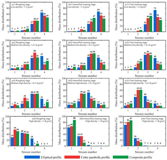
Figure 6.
Influence of the cross-sectional profile on the distribution of particles with different densities in the three-stage separation process.
As separation proceeded to the intensified cleaning stage (Figure 6b1–b4), the composite curve profile provides a more ideal adjustment of particle radial distribution. The proportion of high-density particles in S1 increases substantially from 49.75% in the roughing to 87.76% in the intensified cleaning stage—an increase of 38.01%. This increase is significantly greater than that observed with the cubic parabolic (from 55.36% to 66.47%, an 11.11 percentage-point increase) and the elliptical profiles (from 29.35% to 62.71%, a 33.36 percentage-point increase). Simultaneously, under the composite curve profile, the proportion of medium-high-density particles in the outer streams (S3 + S4) decreases sharply from 68.07% in the roughing stage to 36.40% in the intensified cleaning stage, a reduction of 31.67%, indicating their efficient recovery towards the inner region of the spiral trough.
During the final cleaning stage, as shown in Figure 6c1–c4, the composite curve profile continues to demonstrate superior performance, showing a clearer separation trend of product particles according to density differences. Its mass proportion of high-density particles in the innermost stream S1 is the highest, reaching 86.54%, significantly exceeding the results for the cubic parabolic (81.14%) and elliptical profiles (71.30%). Furthermore, the mass proportion of medium-high density particles in S2 is the highest among the three trough surfaces (reaching 61.06%), while the mass proportion of medium-low density particles at the outer streams (S3 + S4) is the lowest (68.08%). This distribution confirms the composite profile’s effectiveness in directing medium-high and medium-low density particles toward the inner region, thereby reducing contamination of the outer low-density zone by intermediate-density particles and enhancing overall separation precision.
In summary, the cubic parabolic profile is more effective at promoting the inward migration of high-density particles during the roughing stage, whereas the elliptical profile shows superior performance in transporting low-density particles to the outermost stream S4. The composite curve profile effectively combines the advantages of both the elliptical and cubic parabolic geometries [32], significantly enhancing the inward aggregation of high- and intermediate-density particles in the inner region while enabling effective concentration of low-density particles in the outer region.
3.3.2. Trough Inclination Angle Effects on the Three-Stage Separation Process
Figure 7 illustrates the influence of the trough inclination angle on the radial distribution of particles across different density classes during the spiral separation process. In the roughing stage (Figure 7a1–a4), increasing the trough inclination angle to 17° raises the mass proportion of high-density particles in the innermost stream S1 to 49.75%, higher than the 32.54% at 15°. The radial distribution trend of medium-high density particles is similar, with their combined proportion in S1 and S2 reaching 32.65%, higher than the 19.17% at 15°. In contrast, the mass proportion of low-density particles in the outermost stream S4 is only 48.51%, significantly lower than the 76.00% at 15°. These results indicate that increasing the trough inclination angle synchronously enhances the inward migration trend of particles across all density classes.
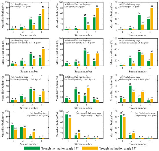
Figure 7.
Influence of the trough inclination angle on the distribution of particles with different densities in the three-stage separation process.
In the intensified cleaning stage, the inward aggregation trend is further amplified at higher trough inclination angles. As shown in Figure 7b1–b4, at a 17° trough inclination angle, the proportion of high-density particles in S1 surges from 49.75% to 87.76%, an increase of 38.01%. In comparison, the device with a 15° inclination angle shows an increase of 42.42% (from 32.54% to 74.96%); Although the magnitude was similar, its lower starting point results in the mass proportion of high-density particles in S1 at the end of the intensified cleaning stage still lagging behind the 17° device. Concurrently, the inward migration behavior of medium-high density particles (1.6–1.8 g/cm3) is also more pronounced at 17°inclination, with the decrease in their proportion in the outer streams (S3 + S4) reaching 31.67%, far greater than the 18.08% decrease observed at the 15° inclination.
During the final cleaning stage, the influence trend of the trough inclination angle on particle radial distribution is significantly less pronounced than in the intensified cleaning stage. As shown in Figure 7c1–c4, relatively speaking, the spiral separator with a 17° trough inclination angle achieves better separation results. Although the mass proportion of high-density particles in S1 decreases slightly from 87.76% to 86.54%, it remains higher than the 78.94% observed at 15°. Moreover, at 17°, the mass proportion of medium-low-density particles in S4 stabilizes around 18.2%, whereas at 15°, the mass proportion of medium-low-density particles in S4 actually increases from 44.99% to 47.33%. This indicates that increasing the trough inclination angle can reduce the mass proportion of medium-low-density particles aggregating at the outer region, which is beneficial for improving separation precision.
In summary, the trough inclination angle is a key factor controlling particle radial distribution [30,31]. An increase in the trough inclination angle significantly enhances the particle inward migration trend, which is conducive to reducing the mass proportion of misplaced intermediate-density particles in the outer streams S3 and S4.
3.3.3. Pitch-to-Diameter Ratio (P/D) Effects on the Three-Stage Separation Process
Figure 8 illustrates the influence of the pitch-to-diameter ratio on the radial distribution of particles across different density classes during the spiral separation process. As shown in Figure 8a1–a4, in the roughing stage, increasing the P/D favors the outward transport of low-density particles (<1.4 g/cm3), with the mass proportion in the outermost stream S4 reaching 76.00%. Furthermore, overall, the radial distribution of intermediate-density particles (1.4–1.8 g/cm3) also expands towards the outer region with increasing P/D. In contrast, reducing the P/D promotes particle aggregation towards the inner region. For example, when the P/D decreases from 0.4 to 0.37, the proportion of high-density particles in S1 rises from 32.54% to 53.42%, an increase of 20.88%; a further reduction to 0.34 results in a noticeably slower growth rate, increasing only from 53.42% to 56.19%, a mere 2.77% increase.
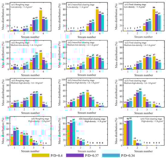
Figure 8.
Influence of the pitch-to-diameter ratio (P/D) on the distribution of particles with different densities in the three-stage separation process.
As separation proceeded to the intensified cleaning stage, shown in Figure 8b1–b4, at a P/D of 0.34, the mass proportion of high-density particles in S1 increases substantially from 56.19% in the roughing stage to 86.91%, an increase of 30.71%. At P/D = 0.37, this increase is 28.95% (reaching 82.37%), while at P/D = 0.4, although the increase is largest (42.42%), the final mass proportion remains the lowest (74.96%). Additionally, reducing the P/D significantly promotes the inward migration of medium-high-density particles (1.6–1.8 g/cm3). At P/D = 0.34, the proportion of this density fraction in the inner region (S1 + S2) increases substantially from 43.19% in the roughing stage to 67.52%, the largest increase of 24.33% (compared to increases of 20.14% at P/D = 0.37 and 18.07% at P/D = 0.4).
Entering the final cleaning stage, the optimizing effect of reducing the P/D on separation continues to be evident. As shown in Figure 8c1–c4, when the P/D decreases from 0.4 to 0.37, the proportion of high-density particles in S1 jumps from 78.94% to 90.32%, an increase of 11.39%; a further decrease in P/D to 0.34 shows a markedly slower growth rate (increasing only from 90.32% to 92.05%, a mere 1.73% increase). However, regarding the misplacement of medium-low-density particles (1.4–1.6 g/cm3) in the outer region (S3 + S4), reducing the P/D alleviates this phenomenon. At P/D = 0.4, the mass proportion of this density fraction in the outer region increases slightly from 87.96% in the intensified cleaning stage to 88.39%. In contrast, at P/D = 0.37, the mass proportion of this density fraction in the outer region decreases from 81.37% in the intensified cleaning stage to 74.91%, a drop of 6.45%; further reducing the P/D to 0.34 results in a decrease from 75.16% to 69.42%, a drop of 5.74%. Given the similar magnitude of decrease, the final total proportion is lowest at P/D = 0.34, indicating that reducing the P/D can decrease the mass proportion of medium-low-density particles aggregating at the outer region, which is beneficial for improving separation precision.
In summary, reducing the P/D can significantly promote the inward migration of high-density and intermediate-density particles towards the inner region (S1), thereby reducing the misplacement behavior affecting low-density particles in the outer region (S3 + S4) and favoring enhanced separation precision [26,29]. However, when the P/D is excessively low (e.g., decreasing from 0.37 to 0.34), its influence on particle radial distribution diminishes noticeably. Furthermore, an overly low P/D carries the risk of hindered pulp flow; therefore, the P/D should be selected cautiously during design.
3.3.4. Mechanistic Interpretation of Structural Parameter Effects
Based on the preceding discussions concerning the effects of the three key structural parameters—cross-sectional profile, trough inclination angle, and pitch-to-diameter ratio (P/D)—on the spiral separation process, the following patterns of control are established. The results indicate that due to the consistent structure of each turn in the separator, the influence of any parameter on the particle distribution trend established during the roughing stage profoundly persists and affects the final outcomes in the subsequent intensified cleaning and final cleaning stages. This implies that analyzing the final product distribution can effectively reflect the macroscopic impact of a given parameter throughout the entire separation process.
The control exerted by the cross-sectional profile on the radial particle distribution essentially stems from the distribution of trough inclination angles predetermined by its geometry, which dictates the force environment and migration paths for particles. As can be seen in Figure 9a, the cubic parabolic profile offers a gentle and continuous variation in inclination from the inner to the middle region (S1–S3), creating a stable and gradually changing separation environment. This allows high-density particles to migrate smoothly and steadily towards the inner region (S1) under a consistently sufficient gravitational component force, leading to efficient enrichment. In contrast, the elliptical profile exhibits an abrupt change in trough inclination across the radius, featuring a distinct inflection point near the inner region where the angle decreases sharply. This results in a significantly lower inclination angle in this region compared to the cubic parabola, even approaching zero. This geometric feature directly triggers a critical “blockage effect at the inner region”: when high-density particles migrate to this zone, the gravitational component driving them inward drops precipitously; the particles lose their primary driving force and form a physical accumulation. This accumulation not only blocks the inward migration path for subsequent medium-high-density particles, but also, through the induced flow turbulence, causes these particles (which should report to the inner region) to be flung back to the middle-outer streams by centrifugal force. This systematically explains the core mechanism behind the overall outward shift and high misplacement rate of high and medium-density particles observed with the elliptical shape. Concurrently, although the elliptical profile possesses a steeper inclination at the outer region (S4), the severe blockage at the inner region forces more pulp flow towards the outer region, increasing the flow velocity in S4. This compensatory flow induced by inner region blockage, within the centrifugal-force-dominated outer region, conversely further enhances the enrichment of low-density particles. The optimized design of the composite curve profile achieves high-precision zoning for particles of all densities, particularly intermediate-density ones, precisely by avoiding inner region blockage, coordinating the trough inclination across the full trough width, and consequently generating a suitable secondary circulation within a stable flow field.
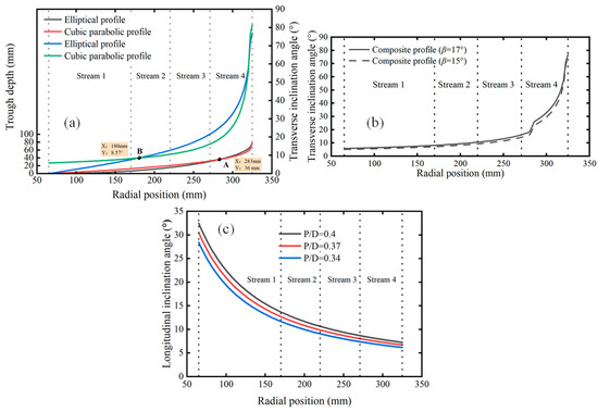
Figure 9.
Features of structural parameters. (a) Variation of local transverse inclination angle and trough depth with radial distance for elliptical and cubic parabolic trough surfaces; (b) Variation of local transverse inclination angle with radial distance for the composite trough surface under different β values; (c) Variation of longitudinal inclination angle with radial distance under different P/D.
The global control of the trough inclination angle over particle radial migration can be essentially attributed to its systematic alteration of the transverse inclination angle at any point on the trough surface (Figure 9b). For a fixed cross-sectional curve, an increase in the trough inclination angle uniformly elevates the transverse inclination angle from the inner to the outer region. This amplifies the gravitational component force driving particles inward, synchronously across all radial positions. This enhancement significantly accelerates the process of high-density and medium-high-density particles reporting to the inner enrichment zone (S1) and improves the enrichment purity. However, the trade-off is a weakening of the centrifugal force’s dominant control over low-density particles. This results in more light particles being retained in the middle-outer streams (S2, S3), unable to be effectively transported to the outermost region (S4), thereby impairing the separation efficiency of the light product.
The Pitch-to-Diameter ratio (P/D) fundamentally governs particle gathering behavior by systematically modulating the centrifugal force exerted on particles through pitch variation. An increase in the P/D raises the longitudinal inclination angle of the trough surface (Figure 9c), which in turn increases the pulp flow velocity and significantly enhances the centrifugal force [15]. This enhanced centrifugal force intensifies the outward-throwing motion of all particles, particularly low-density particles, thereby transporting a greater proportion of them toward the outer region. However, an excessively strong centrifugal force can also entrain some intermediate-density particles that should otherwise report to the inner or middle regions, causing them to misplace to the outer region. Concurrently, the flow film thins and its velocity rises, consequently attenuating the development and efficacy of the inner secondary circulation and diminishing the duration available for effective particle separation. Ultimately, this may lead to decreased content of heavy product in the inner region S1 and increased misplacement of light product. Conversely, appropriately reducing the P/D decreases the longitudinal inclination angle and pulp flow velocity, directly weakening the centrifugal force. This not only suppresses the excessive outward throwing of particles but also promotes flow film thickening and velocity reduction in the inner and middle regions of the spiral trough. These conditions favor the establishment of a stable laminar flow environment and a robust radial secondary circulation. The enhanced secondary circulation more effectively transports high- and medium-high-density particles inward, enabling their efficient enrichment. Simultaneously, the prolonged residence time allows for more precise density-based stratification.
3.4. Novel Spiral Separator Design
3.4.1. Design Rationale for a Novel Multi-Stage Spiral Separator
The experimental deconstruction of the separation process (Section 3.2) and the mechanistic analysis of structural parameter effects (Section 3.3) collectively demonstrate that the spiral separation is a staged process, with each stage dominated by distinct fluid-particle dynamics. This fundamental understanding leads to a core design concept: stage-optimized intensification. This concept dictates that the structural parameters of the spiral trough should be specifically configured to enhance the dominant separation mechanism at each respective stage, rather than maintaining a constant geometry throughout. The novel multi-stage spiral separator was developed precisely upon this concept. The design rationales for each section are as follows:
- (1)
- Design rationale for the roughing-stage trough parameters
The primary objective of the roughing stage is to achieve rapid stratification of particles and establish a high-purity enrichment starting point for the heavy mineral system. Preliminary tests on Spiral #6 (P/D = 0.34, Trough Inclination = 15°) clearly demonstrated that a lower pitch-to-diameter ratio (P/D) significantly promotes the inward migration of high-density particles: after the first turn, the mass distribution of high-density particles in the inner stream (S1) reached 56.19%. This is 23.65% higher than the 32.54% observed under equivalent conditions for Spiral #4 (P/D = 0.40, Trough Inclination = 15°). Concurrently, a higher trough inclination angle enhances the gravitational separation effect. Tests on Spiral #3 (P/D = 0.40, Trough Inclination = 17°) showed a mass distribution of high-density particles in S1 (49.75%), which was 17.21% higher than that of Spiral #4 (32.54%). Therefore, to intensify the roughing stage, the lowest P/D (0.34) and a customized highest trough inclination angle (21°) were employed in the roughing stage (Turns 1–2), utilizing the strongest inward flow regime to rapidly achieve enrichment of high-density particles. Based on the superior overall performance of the composite-curve trough during the roughing stage in prior tests (achieving 49.75% high-density distribution in S1, outperforming the elliptical profile’s 29.35%), this trough type was adopted for all stages. Furthermore, the roughing stage was extended from the conventional single turn to two turns to compensate for the separation time required by the strong flow regime and to provide sufficient path length for the inward migration of medium-high density particles.
- (2)
- Design rationale for the intensified cleaning stage trough parameters
The core objective of the intensified cleaning stage is the precise separation and rejection of high-density and medium-high-density particles, while minimizing the misplacement of low-density clean coal. Experiments indicated that a higher P/D facilitates the outward migration of particles overall, as validated by Spiral #4 (P/D = 0.4, Trough Inclination = 15°), where the mass distribution of low-density particles in the outermost stream (S4) reached 76.00% even in the first turn. Conversely, a lower trough inclination angle weakens the secondary circulation intensity, reducing the driving force for particle movement towards the inner region. Consequently, the intensified cleaning stage was subdivided into two segments for precise control. The primary task of Intensified Cleaning Segment I (Turns 3–4) is to discharge the enriched high-density particles through the reject port. This segment employs a higher P/D (0.4) and a lower trough inclination angle (15°). This combination aims to create an overall “pushing outward” flow field at the beginning of the intensified cleaning stage, with the core purpose of “rescuing” the small amount of low-density clean coal that might have been entrapped near the inner edge due to the strong inward flow regime in the roughing stage, thereby effectively preventing clean coal misplacement during the reject discharge at the end of this segment. The core goal of Intensified Cleaning Segment II (Turns 5–6) is to further remove residual high-density and enriched medium-high-density particles. Lower P/D and higher inclination promote inward migration of medium-to-high density particles (e.g., on Spiral #3 (Trough Inclination = 17°), the mass distribution of medium-to-high density particles in the outer region (S3 + S4) decreased by 31.67% from the first to third rotation; on Spiral #5 (P/D = 0.37), the mass distribution of medium-high-density particles in the inner region (S1 + S2) increased by 20.14% from the first to the third turn). Thus, this segment adopts a moderate P/D (0.37) and a trough inclination angle (17°) to achieve the progressive recovery and targeted rejection of medium-high density particles. The stepwise reject ports installed at the ends of Turns 4 and 6, named R4t and R6t, allow for the timely removal of separated heavy minerals from the system. This not only prevents their ineffective recirculation and re-contamination but also directly “unloads” the system for the subsequent scavenging stage, optimizing the separation space.
- (3)
- Design rationale for the final cleaning stage trough parameters
The final task of the final cleaning stage is to maximize the yield of low-density clean coal and achieve the final product separation after system purification. Prior tests clearly demonstrated that a very high P/D is the most effective factor driving the enrichment of low-density particles towards the outer edge. Data from Spiral #4 (P/D = 0.4) is decisive: throughout the separation process, the mass distribution of low-density particles in its S4 stream remained high (76.00% at Turn 1, 79.56% at Turn 5), significantly outperforming Spiral #6 (P/D = 0.34), which ranged from 41.17% to 57.18%. Therefore, to achieve the core objective of maximizing clean coal yield, a very high P/D (0.45) and a lower trough inclination angle (15°) were customized for the final cleaning stage (Turns 7–8). This parameter combination aims to establish a centrifugal force-dominated, strong outward flow field at the end of the separation process, performing a final “scavenging” of the pulp—now primarily consisting of middling and clean coal after prior purification—forcibly driving the low-density particles towards the outermost product zone, thereby securing the final clean coal recovery. This design represents a strategic choice based on the demonstrated dominant influence of P/D on low-density particle distribution, aimed at optimizing the key economic indicator. Specific parameter selections are provided in Table 6.
Table 6.
The novel design of spiral separator.
3.4.2. Performance Evaluation of the Novel Multi-Stage Spiral Separator
To assess the separation performance of the combined spiral separator, a beneficiation test was conducted using 1–0.25 mm coarse coal slime at a feed flow rate of 2.0 m3/h and a feed concentration of 25%. Products collected from each sampling launder were subjected to sink-float analysis for evaluation.
As illustrated in Figure 10a,b, at the 4th turn—corresponding to the first gangue discharge—both the yield and ash content of the discharged material were high, removing over 85% of high-density particles. In contrast, at the 6th turn (second gangue discharge), the yield and ash content decreased significantly, with both residual high-density particles and more than 60% of medium-high-density particles being discharged.
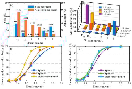
Figure 10.
Sorting experiment results and comparison of combined spiral sorters. (a) Yield and ash content; (b) Distribution of particles across different density fractions; (c) Performance comparison between the combined spiral separator and Spiral #1 & Spiral #4; (d) Performance comparison between the combined spiral separator and Spiral #2 & Spiral #6.
On the spiral trough, over 90% of medium- and low-density particles accumulated in the outer region, with very few present in the inner region. Yield increased radially outward, while ash content—generally low—decreased radially, reaching a minimum of only 8.94% at the outermost edge. Furthermore, the calculated combined ash content of products collected in streams S3 and S4 was 9.94%.
For comparison, the top-performing conventional separators, Spiral #1 and Spiral #4 (selected from six conventional units), were evaluated alongside the combined spiral separator. Results are shown in Figure 10c and Table 7. At a target clean coal ash content of 9.94%, Spiral #1 and Spiral #4 achieved quantity efficiencies of 71.20% and 77.50%, respectively, whereas the combined separator attained a significantly higher efficiency of 94.74%, confirming its superior separation performance. Additionally, Figure 10c shows that the combined separator exhibits a steeper heavy product distribution curve, indicating advantages in both separation density and operational accuracy.
Table 7.
Comparison of sorting effects.
Further comparison was made with Spiral #2 and Spiral #6, the two most accurate separators among the six conventional units. As shown in Figure 10d, at similar separation densities, the heavy product distribution curve of the combined separator is steeper than those of Spiral #2 and Spiral #6, reflecting its higher separation accuracy. A comprehensive analysis of quantity efficiency, separation density, and accuracy confirms that the combined spiral separator outperforms all six conventional spiral separators in overall performance.
3.4.3. Image of Particle Distribution During the Separation Process
To validate the efficacy of the proposed stage-optimized separation intensification strategy, tracer particle experiments were conducted to visually track and analyze particle behavior throughout the separation process. Tracer particles comprised white PVC, orange PVC, green PVC, black PVC, and purple quartz sand, corresponding to specific density classes: <1.3 g/cm3, 1.3–1.5 g/cm3, 1.5–1.6 g/cm3, 1.6–1.8 g/cm3, and >1.8 g/cm3, respectively. These tracers were used to replace corresponding density fractions in the raw coal to match its density and size composition. A slurry with a mass concentration of 25% was then prepared for the tracing tests.
The migration patterns of each colored tracer group during the separation process are illustrated in Figure 11 and can be summarized as follows:
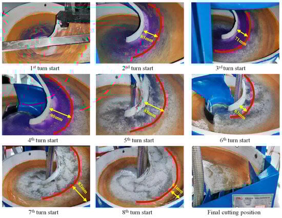
Figure 11.
Distribution of tracer particles in each turn.
Roughing stage: High-density purple quartz particles converged toward the inner edge, achieving initial stratification by density (color).
Intensified cleaning stage I: Medium-density and low-density particles migrated outward, while the purple inner band (high-density particles) simultaneously expanded.
Intensified cleaning stage II: Residual high-density (purple) and a portion of medium-high-density (black, 1.6–1.8 g/cm3) particles re-accumulated along the inner edge.
Final cleaning stage: Low-density and medium-density particles became stably enriched in the outer region of the trough.
These observations confirm that the actual particle dynamics align well with the anticipated behavior underpinning the stage-optimized separation intensification strategy, thereby validating its conceptual framework.
4. Conclusions
This study systematically deconstructed the spiral separation process of 1–0.25 mm coarse coal slime through industrial-scale experiments with six distinct spiral configurations. The fundamental insights gained were successfully translated into the development of a novel, high-efficiency separator. The principal conclusions are drawn as follows:
(1) This work reveals that the spiral separation process is a dynamic and continuous system, which can be delineated into three functionally distinct stages based on particle distribution characteristics. The roughing stage (1st turn) accomplishes the rapid segregation and enrichment of low-density and high-density particles. The intensified cleaning stage (2nd–3rd turns) dominates the radial migration and zoning of intermediate-density particles, with simultaneous further concentration of light/heavy particles towards the outer/inner region. The final cleaning stage (4th–5th turns) focuses on the transport of already-segregated particles and the fine-tuning of misplaced particles.
(2) The influence of key structural parameters was quantitatively elucidated, providing a basis for targeted optimization. The elliptical trough profile favored the transport of low-density particles to the outer region, while the cubic parabolic profile promoted the accumulation of high-density particles towards the inner region. The composite profile demonstrated superior overall performance by effectively balancing the separation of both high-density and low-density fractions. Furthermore, increasing the trough inclination angle and reducing the pitch-to-diameter ratio were both confirmed to significantly enhance the inward migration trend of medium- and high-density particles, thereby improving separation sharpness.
(3) Building on these findings, we propose a “stage-optimized intensification” design concept and validate its efficacy through a novel spiral separator. The core of this concept is the stage-specific coordination of structural parameters based on the dominant separation task of each stage. Beneficiation tests confirmed the exceptional performance of the newly designed separator, which achieved a remarkable separation efficiency of 94.74% at a clean coal ash content of 9.94%, substantially outperforming conventional high-performance spirals. This outcome provides an excellent engineering solution for the efficient processing of coarse coal slime.
Author Contributions
Writing—original draft preparation, M.X.; validation, funding acquisition, writing—review & editing, G.Y.; methodology, Q.L.; data curation, X.D., Y.F., X.M., S.L., R.C., C.Z. and B.Z. All authors have read and agreed to the published version of the manuscript.
Funding
This research was funded by the National Natural Science Foundation of China (grant number 52104260), the China Postdoctoral Science Foundation (grant number 2025M781730) and the National Natural Science Foundation of China (grant number 52504303).
Data Availability Statement
The data presented in this study are available upon request from the corresponding author. The data are not publicly available due to the inclusion of technical details pertaining to the separation performance of a custom-built instrument.
Acknowledgments
All authors would like to acknowledge the Shanxi Research Institute for Clean Energy, Tsinghua University, for providing the experimental site, and Qinyang Qinlong Chemical Anticorrosion Co., Ltd. for equipment support.
Conflicts of Interest
Author Guichuan Ye, Qingxiang Liu was employed by the company Qinyang Qinlong Chemical Antiseptic Co., Ltd. The remaining authors declare that the research was conducted in the absence of any commercial or financial relationships that could be construed as a potential conflict of interest.
References
- Tripathy, S.K.; Murthy, Y.R.; Singh, V.; Farrokhpay, S.; Filippov, L.O. Improving the Quality of Ferruginous Chromite Concentrates Via Physical Separation Methods. Minerals 2019, 9, 667. [Google Scholar] [CrossRef]
- Izerdem, D. Low-Grade Chromite Beneficiation Through Spiral Concentration: A Review from the Turkish Market Perspective. Miner. Process. Extr. Metall. Rev. 2025, 46, 436–456. [Google Scholar] [CrossRef]
- Ma, G.X.; Bu, X.N.; Xie, G.Y.; Peng, Y.L.; Sha, J.; Xia, W.C.; Wu, E.D. Comparative Study of Separation Performance of a Spiral and Dense-medium Cyclone on Cleaning Coal. Int. J. Coal Prep. Util. 2021, 41, 108–116. [Google Scholar] [CrossRef]
- Rao, R.B.; Srikant, S.S. Judicious combinations of gravity, magnetic, electrostatic separators and microwave heat energy on recovery of ilmenite from Humma lean grade beach placer deposit. J. Microw. Power Electromagn. Energy 2024, 58, 342–357. [Google Scholar] [CrossRef]
- Izerdem, D. A Comparative Experimental Analysis of the Effect of Spiral Geometry on the Separation of Fine Chromite Particles. Part 1: Potential Downstream Impacts. Min. Metall. Explor. 2024, 41, 2619–2634. [Google Scholar] [CrossRef]
- Izerdem, D. A Comparative Experimental Analysis of the Effect of Spiral Geometry on the Separation of Fine Chromite Particles. Part 2: Image Analysis Application in a High-Capacity Spiral. Min. Metall. Explor. 2025, 42, 3933–3944. [Google Scholar] [CrossRef]
- Gao, Y.; Qi, Y.X.; Zhang, C.F.; Wang, W.D.; Tu, Y.A.; Zhu, Z.Q.; Xu, Z.Q. Combined gravity separation-oil agglomeration separation of coal gasification fine slag and metal elements risk characteristics in separated products. Int. J. Coal Prep. Util. 2025, 1–21. [Google Scholar] [CrossRef]
- Yu, W.; Zhang, H.L.; Wang, X.B.; Rahman, Z.U.; Shi, Z.C.; Bai, Y.H.; Wang, G.S.; Chen, Y.Q.; Wang, J.J.; Liu, L.J. Enrichment of residual carbon from coal gasification fine slag by spiral separator. J. Environ. Manag. 2022, 315, 115149. [Google Scholar] [CrossRef]
- Ye, G.; Ma, L.; Huang, G.; Yu, Y.; Sun, X.; Wu, L. Dynamic and optimization analysis of spiral separator. J. China Coal Soc. 2017, 42, 479–485. [Google Scholar] [CrossRef]
- Ding, L.Y.; Burnett, S.C.; Bertozzi, A.L. Equilibrium theory of bidensity particle-laden suspensions in thin-film flow down a spiral separator. Phys. Fluids 2025, 37, 023397. [Google Scholar] [CrossRef]
- Jain, P.K. A novel concept of composite coefficient of friction for slurry systems and development of flow equations for spiral concentrators. Powder Technol. 2021, 386, 411–419. [Google Scholar] [CrossRef]
- Jain, P.K. An analytical approach to explain complex flow in spiral concentrator and development of flow equations. Miner. Eng. 2021, 174, 107027. [Google Scholar] [CrossRef]
- Sudikondala, P.; Mangadoddy, N.; Kumar, M.; Tripathy, S.K.; Yanamandra, R.M. CFD Modelling of Spiral Concentrator-Prediction of Comprehensive Fluid Flow Field and Particle Segregation. Miner. Eng. 2022, 183, 107570. [Google Scholar] [CrossRef]
- Sudikondala, P.; Mangadoddy, N.; Tripathy, S.K.; Yanamandra, R.M. CFD Modelling of the Spiral Concentrator at Moderate Feed Solids Content-Prediction of Particle Segregation. Trans. Indian Inst. Met. 2024, 77, 4193–4204. [Google Scholar] [CrossRef]
- Ye, G.C.; Ma, L.Q.; Alberini, F.; Xu, Q.; Huang, G.; Yu, Y.X. Numerical studies of the effects of design parameters on flow fields in spiral concentrators. Int. J. Coal Prep. Util. 2022, 42, 67–81. [Google Scholar] [CrossRef]
- Doheim, M.A.; Gawad, A.F.A.; Mahran, G.M.A.; Abu-Ali, M.H.; Rizk, A.M. Numerical simulation of particulate-flow in spiral separators: Part I. Low solids concentration (0.3% & 3% solids). Appl. Math. Model. 2013, 37, 198–215. [Google Scholar] [CrossRef]
- Mahran, G.M.A.; Doheim, M.A.; AbdelGawad, A.F.; Abu-Ali, M.H.; Rizk, A.M. Numerical simulation of particulate-flow in spiral separators (15% solids). Afinidad 2015, 72, 223–229. [Google Scholar]
- Meng, L.G.; Gao, S.L.; Wei, D.Z.; Cui, B.Y.; Shen, Y.B.; Song, Z.G. Investigation on the evolution of flow field stability in a spiral separator. Miner. Eng. 2021, 174, 107224. [Google Scholar] [CrossRef]
- Meng, L.G.; Gao, S.L.; Wei, D.Z.; Zhao, Q.; Cui, B.Y.; Shen, Y.B.; Song, Z.G. Particulate flow modelling in a spiral separator by using the Eulerian multi-fluid VOF approach. Int. J. Min. Sci. Technol. 2023, 33, 251–263. [Google Scholar] [CrossRef]
- Boucher, D.; Deng, Z.; Leadbeater, T.; Langlois, R.; Renaud, M.; Waters, K.E. PEPT studies of heavy particle flow within a spiral concentrator. Miner. Eng. 2014, 62, 120–128. [Google Scholar] [CrossRef]
- Boucher, D.; Deng, Z.; Leadbeater, T.W.; Langlois, R.; Waters, K.E. Speed analysis of quartz and hematite particles in a spiral concentrator by PEPT. Miner. Eng. 2016, 91, 86–91. [Google Scholar] [CrossRef]
- Liu, P.; Ye, G.; Fan, Y.; Dong, X.; Ma, X. CFD-DEM simulation of fluid particle spatial distribution characteristics inthe whole process of fine coal spiral separation. J. China Coal Soc. 2023, 48, 4595–4606. [Google Scholar] [CrossRef]
- Meng, L.; Gao, S.; Zhou, X.; Wei, D. Influence of the Inlet Flow Rate on Flow Field Evolution and Mineral Particle Distribution in the First Turn of Spiral Separators. J. Northeast. Univ. 2023, 44, 856–862. [Google Scholar]
- Huang, B.; Xu, Q.; Xu, H.; Ye, G.; Liu, X. Numerical simulation of flow field and particle motion behavior in spiral separator. J. China Univ. Min. Technol. 2019, 48, 655–661. [Google Scholar] [CrossRef]
- Liu, H.Z.; Wang, J. Impact of inlet flow rate on dynamic liquid film thickness and flow stability in spiral concentrator. Powder Technol. 2025, 466, 121472. [Google Scholar] [CrossRef]
- Gao, S.L.; Zhou, X.H.; Meng, L.G.; Zhao, Q.; Liu, W.G. Variation of Flow Hydrodynamic Parameters and Prediction of Particle Separation Indices in the Spiral Concentrator with the Regulation of Pitch-Diameter Ratio. Separations 2023, 10, 410. [Google Scholar] [CrossRef]
- Ye, G.C.A.; Liu, Q.X.; Ma, L.Q.; Dong, X.S. CFD-DEM investigation of fluid and particle motion behaviors in initial stage of spiral separation process at low solids concentration. Miner. Process. Extr. Metall. Rev. 2023, 44, 475–480. [Google Scholar] [CrossRef]
- Wang, J.; Liu, H.Z.; Zou, Q.H.; Hu, J. Experimental Study on Spatiotemporal Evolution Mechanisms of Roll Waves and Their Impact on Particle Separation Behavior in Spiral Concentrators. Separations 2025, 12, 245. [Google Scholar] [CrossRef]
- Gao, S.; Zhou, X.; Wang, Q.; Liu, C. Evolution of secondary circulation and prediction of particles separation efficiency in spirals with regulation of pitch-diameter ratio. J. Cent. South Univ. 2024, 55, 4100–4110. [Google Scholar]
- Meng, L.G.; Gao, S.L.; Liu, T.L.; Kuang, J.Z.; Yu, M.M. Effect of the downward bevel angle on the particle radial migration behaviour and secondary flow in spiral separators. Miner. Eng. 2025, 233, 109646. [Google Scholar] [CrossRef]
- Wang, Z.B.; Chang, Y.Z.; Zhang, W.W.; Wang, C.; Liang, A. Gas-liquid flow characteristics of spiral separators with different downward bevel angles. Phys. Fluids 2025, 37, 093376. [Google Scholar] [CrossRef]
- Ye, G.C.; Huo, Y.Y.; Li, C.F.; Deng, C.; Yu, Y.X.; Huang, G.; Ma, L.Q. A comparative study of trough profile and operating parameters performance in spiral concentrator. Int. J. Coal Prep. Util. 2021, 41, 678–691. [Google Scholar] [CrossRef]
- Gao, S.L.; Meng, L.G.; Zhou, X.H.; Shen, Y.B.; Cui, B.Y.; Song, Z.G. Design of partial cross-sectional geometry and prediction of separation performance in the spiral separator. Sep. Sci. Technol. 2022, 57, 2127–2144. [Google Scholar] [CrossRef]
- Gao, S.L.; Wang, Q.; Zhou, X.H.; Liu, C.Y.; Shen, Y.B.; Cui, B.Y. Effect of the Cross-Sectional Geometry of the Mixed Particle Zone on the Spiral Separation Process and Its Structural Optimization. Minerals 2024, 14, 1251. [Google Scholar] [CrossRef]
- Meng, L.G.; Gao, S.L.; Wei, D.Z.; Cui, B.Y.; Shen, Y.B.; Song, Z.G.; Yuan, J. Effects of cross-sectional geometry on flow characteristics in spiral separators. Sep. Sci. Technol. 2021, 56, 2967–2977. [Google Scholar] [CrossRef]
- Arnold, D.J.; Stokes, Y.M.; Green, J.E.F. Particle-laden thin-film flow in helical channels with arbitrary shallow cross-sectional shape. Phys. Fluids 2019, 31, 073305. [Google Scholar] [CrossRef]
- Gao, S.L.; Zhou, X.H.; Li, B.C.; Wang, Q.; Liu, C.Y. Effect of Wall Roughness in the Middle Zone of Spiral Concentrator on the Flow Field Evolution of Hematite-Quartz Slurry and Particle Separation Behaviour. Minerals 2025, 15, 208. [Google Scholar] [CrossRef]
- Zhou, X.; Gao, S.; Meng, L.; Zhao, Q. Influence of Wall Roughness on Slurry Flow and Particles Separation Behaviors in Spirals. J. Northeast. Univ. 2023, 44, 1769–1777. [Google Scholar]


Disclaimer/Publisher’s Note: The statements, opinions and data contained in all publications are solely those of the individual author(s) and contributor(s) and not of MDPI and/or the editor(s). MDPI and/or the editor(s) disclaim responsibility for any injury to people or property resulting from any ideas, methods, instructions or products referred to in the content. |
© 2026 by the authors. Licensee MDPI, Basel, Switzerland. This article is an open access article distributed under the terms and conditions of the Creative Commons Attribution (CC BY) license.