Abstract
The replacement of copper metal starter-sheet cathodes with the use of permanent cathode technology, in which the target metal is plated onto an inert blank template, has enabled significant benefits in the copper electrowinning process. These include the application of significantly higher current density, which reduces tankhouse footprint and increases process intensity per unit area; improved operator safety with less reliance on manual electrode handling; and the implementation of process automation and robotics. Cathodes of >99.99% chemical purity and with a smooth and aesthetic surface morphology are consistently produced. This review considers the evolution and development of the permanent cathode process, its commercial adoption across the global copper industry, and the current technology status.
1. Introduction
Approximately 17% (4.5 Mt/a) of the global primary copper cathode production originates from hydrometallurgical processing of oxide and secondary sulfide feedstocks [1,2]. Of this, the Democratic Republic of Congo had the largest production capacity in 2024 (45%; 2.12 Mt), followed by Chile (27.5%; 1.28 Mt) [3]. The flowsheet typically comprises sequential steps of leaching in sulfuric acid, solution purification by solvent extraction, and then electrowinning [4], which can produce cathodes of >99.99% purity that meet the specification for London Metal Exchange Grade A copper [5]. Some base metal refineries electrowin copper directly from the impure leach liquor, which typically comprises a high-nickel sulfate matrix.
The electrowinning process uses direct electrical current to reduce the copper ions in an acidic sulfate electrolyte to copper metal at a cathode. The anode material is usually a lead alloy, although a few tankhouses employ titanium mesh anodes. The respective reactions are given below [4].
Cathode: Cu2+ + 2e− → Cu0(pure) E0 = +0.34 V
Anode: H2O → ½O2 + 2H+ + 2e− E0 = −1.23 V
Overall: Cu2+ + H2O → Cu0(pure) + ½O2 + 2H+ E0 = 0.89 V
The energy requirement for electrowinning is ~2.2 MWh/t Cu [4,6,7], of which the two main voltage contributions are the thermodynamic potential of Equation (3) and the anode overpotential [8]; nevertheless, the ohmic drop across the cell hardware and current inefficiencies owing to short circuits and stray currents are significant contributors to overall energy usage. Developments that improve electrical efficiency and reduce power consumption are therefore of considerable interest. This paper reviews the contributions of the permanent cathode process to energy efficiency, process intensification, and product quality, and discusses trends in the adoption of this technology in the copper industry over the past quarter-century.
2. Evolution of Permanent Cathode Blank Technologies
The art of metal electrorefining was first developed and patented in 1865 by James Elkington, whose work led to the construction of the first copper electrorefinery in Newark, NJ, USA, in 1883 [9]. Commercialization of direct copper electrowinning occurred in the early 20th century (1912–1915) in Chuquicamata, Chile [7]. Ranchers Bluebird, Arizona, USA, was the first commercial plant to produce saleable copper cathodes by utilizing a solvent-extraction step prior to electrowinning in 1968 [7,9]. These developments in electrolytic processing of copper all made use of starter-sheet technology. For over 50 years, starter-sheet cathodes, as illustrated in Figure 1a, were used in electrorefining and electrowinning applications. These cathodes typically make use of a copper hanger bar, a copper starter sheet or blade, and a pair of loops or straps used to suspend the sheet within an electrolyte bath [10].
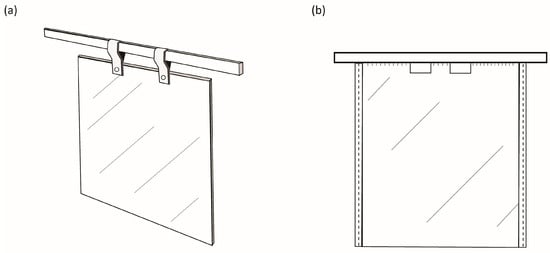
Figure 1.
(a) Typical starter-sheet cathode used in electrorefining and electrowinning, comprising a copper metal sheet attached to a copper hanger bar using copper straps. (b) Permanent stainless-steel cathode blank design first used at Mt Isa Mines in 1978.
2.1. Challenges Associated with Starter-Sheet Technology
Common challenges are associated with the use of starter-sheet technology that impact the safe, sustainable, and efficient running of electrolytic operations. Major challenges include the need for extensive preparation of the thin copper sheets derived from manual stripping, machining, loop cutting and bending, and sheet stiffening and straightening, and the precision required for manual insertion into the electrolytic cells, which add to the manual intensity of the operation [11]. Replacement of fallen cathodes due to broken straps is a safety risk to operators, especially in plants that operate at higher current densities. Owing to inconsistent electrode geometries and the lack of dimensional stability of starter sheets in an electrolytic cell, greater efforts from the operations teams are required to ensure continuous fault checking and rectification to maintain electrode spacing to prevent short circuits and poor contacts within the cells [12,13]. Dimensional instability associated with starter-sheet cathodes limits the ability of tankhouses to sustainably run at higher current densities to enhance productivity in terms of production per plant footprint.
Conventional starter sheets can only be used once [10]. Operations consequently need to dedicate specific electrolytic cells to produce starter sheets, which adds to labour intensity and tankhouse footprint. Starter sheets may be rigid and maintain their stability when initially inserted into cells; however, they frequently warp in service due to electrolyte hydrodynamics [10]. This leads to the creation of current density hot spots caused by the reduced electrode spacing, which will result in poor cathode quality, including formation of dendrites and nodular growth, which can cause electrical short circuits. In addition, the loops attached to the starter sheet may make limited contact with the hanger bar if not correctly attached or well prepared, which can increase electrical resistance and, hence, power costs [10].
Using a copper inventory as a copper starter-sheet stock is an important consideration for an electrolytic refinery. Operations that make use of starter sheets need to hold a minimum stock of starter sheets on the floor to enable timeous harvesting of production cathodes. The lack of availability of sufficient prepared starter sheets ready to be inserted into cells during harvesting activities poses a serious risk to production continuity [13]. Poor process performance and lack of quality in generating starter sheets further exacerbate the overall operability of an electrowinning or electrorefining tankhouse.
2.2. Development of ISA Permanent Cathode Technology
The first development and use of permanent cathodes was reported in 1978 by Ian Perry and colleagues at Mount Isa Mines Limited, a holding of Copper Refineries (Pty) Ltd. (Queensland, Australia), where this technology was implemented during modernization of the refinery and electrorefining process after about 20 years of operation [8]. A common challenge in the global electrowinning industry at the time was the cost of labour and the manner in which daily operational activities were executed: a fixed number of tasks were carried out by a fixed number of tankhouse employees. According to work practice then, production bottlenecks occurred if the labour force was unable to harvest all the production that was due, further constraining operational performance. The primary motivation behind the development of the permanent cathode technology was to decrease manual intensity for the labour force and to improve operational safety [8].
This novel technology involved the use of a stainless-steel blank cathode, onto which copper was plated to the required mass and then stripped. The blank could be cleaned and reused for many cycles. This approach was revolutionary in the copper industry. The electrorefining operation was significantly automated with the installation of a stripping machine that stripped the direct-plated copper from the stainless-steel blanks, and the entire starter-sheet production section became obsolete [8,10]. Experimental use of the new permanent cathodes proved extremely successful, so, after considerable testing and implementation in the rest of the electrorefinery, the technology was marketed to the rest of the world in 1980 as the ‘ISA Process’ [8].
The original invention, as outlined by Perry [10], included a flat stainless-steel starter-sheet blade (~3.25 mm thick) that was welded to a stainless-steel I-beam hanger bar with an enveloping copper cladding (~2.5 mm thickness), inclusive of the cladding of a small upper portion of the sheet itself (~15 mm down the blade). This improved electrical conductivity of the hanger bar allowed for sufficient electron flow to the cathode blade and aided to some degree in corrosion resistance [10]. Furthermore, the invention made use of edging in the form of plastic beading on the cathode sides to prevent complete plating of the blank around the sides, which would make stripping activities difficult. The use of wax to mask the bottom edge was recommended to aid in stripping, but was deemed less important than the beading on the cathode sides [10]. Use of these plastic edge strips and the wax layer at the base of the cathode allowed for two separate copper sheet products from each cathode plate. Figure 1b indicates an elevated view of the first permanent cathode, which contained windows in the blade for ease of haulage by crane and subsequent electrode handling to fulfil automated stripping activities.
Developments from the original ISA Process cathode to improve and sustain process performance led to the subsequent introductions of the ISA 2000, ISA BR, and ISA AB cathode designs. Weston and Webb [12] documented various developments in hanger-bar designs that occurred, including moving to a more-rounded-bottom I-beam (~1.3 mm copper coating) to improve cell verticality, a rectangular hollow-section stainless-steel bar including a copper coating (~2.5 mm) with a flat top, and a rectangular hollow-section stainless-steel bar including a copper coating (~2.5 mm) with a rounded top.
The need to eliminate wax usage on the cathode blades incentivized development of the ISA 2000 process technology. This design made use of a 90° V-groove that was machined into the bottom edge of the cathode blade to effect separation of the two sheets of copper per cathode blank by ISA Process stripping machines [7,14,15]. A typical original ISA Process cathode is depicted in Figure 2a, with the ISA Process 2000 cathode pictured in Figure 2b. The evolution of the hanger bar designs can be seen in Figure 3.
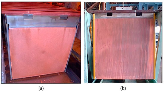
Figure 2.
(a) Original ISA Process electrowinning cathode design. (b) ISA Process 2000 cathode design, with V-groove at bottom (not visible) (Reproduced from [9] with permission from Glencore Technology).

Figure 3.
Evolution of cathode hanger-bar design developments in the ISA Process (Adapted from [15] with permission from Glencore Technology).
Further improvements in the ISA 2000 cathode to improve the stripping efficiency related to its V-groves led to the design of the ISA 2000 AB cathode. The AB cathode design included 45° chamfered corners on the bottom of the cathode blank that ran through the bottom length and up the chamfered corners (Figure 4) [14]. The idea behind this design was to maximize the tearing action to initiate splitting of the copper sheets during the stripping process, especially if delamination of the copper from the blank had occurred [15]. It was reported that delamination made the effect of the V-grove worthless with respect to ease of stripping and producing two separate cathode sheets. This consequently affected the stripping time and could require additional machine requirements to split the hinged-type copper sheet. Power outages in operations that made use of the ISA 2000 technology were said to worsen these detrimental effects of the V-groove due to the resultant altered growth patterns of the electrodeposit crystals, which caused delamination of the initial copper growth [15]. Following a controlled stepwise current ramp-up protocol after a power outage will minimize delamination, in addition to retaining the protective oxide coating on the anodes to minimize lead corrosion.
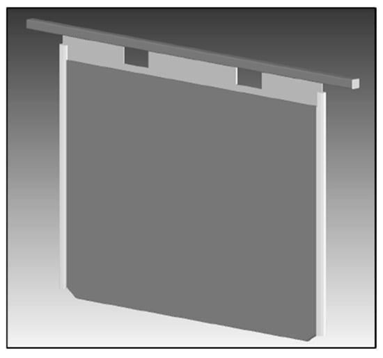
Figure 4.
ISA 2000 AB cathode with chamfered bottom edges at 45° and V-groove along the length and up the chamfered corners (Figure 4 from [16] in the Proceedings of Copper 2003 5th International Conference, Vol. 5. Reprinted with permission of the Canadian Institute of Mining, Metallurgy and Petroleum).
The ISA Process evolved further with the introduction of the ISA BR cathode, which was marketed as a lower-resistance cathode and hence reduced power costs. According to Webb and Weston [15], the BR design incorporated an extended portion of copper plating from the hanger bar onto the stainless-steel blade by ~55 mm down the blade, compared with the ~15 mm copper plating length in the standard ISA Process cathode. The copper plating thickness was subsequently also increased to ~3.0 mm in comparison with the original ~2.5 mm thickness to improve the corrosion resistance when cathodes are subjected to highly acidic conditions [15]. Extension of the copper plating further down the blade reportedly reduced the electrical resistance between the electrodeposit and the electrolyte due to the shorter distance that the current now needed to travel between the stainless-steel blade and solution line [15]. In comparing these two metal types, through which current is required to flow, Eastwood et al. [16] reported the resistance of stainless steel to be 74 µΩ·cm at 50 °C, which is almost 42 times that of copper (1.8 µΩ·cm at 50 °C). The lower-resistance BR cathode is shown in Figure 5. This cathode was initially tested in the Mt Isa Mines copper refinery before being rolled out in a larger trial at Compañía Minera Zaldívar, Chile, where the electrical performance results closely confirmed the initial testwork results obtained at the Townsville refinery [12].
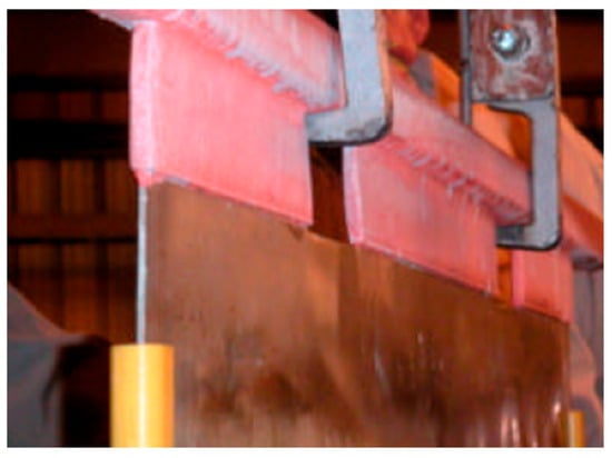
Figure 5.
ISA cathode BR in service at Compañía Minera Zaldívar, Chile (Figure 1 from [12] in the Proceedings of Copper 2003 5th International Conference, Vol. 5. Reprinted with permission of the Canadian Institute of Mining, Metallurgy and Petroleum).
2.3. Development of KIDD Permanent Cathode Technology
A second form of permanent cathode technology was developed by Falconbridge in the 1980s, and became known as the ‘KIDD Process’. KIDD permanent cathodes were first implemented in 1985 in the Kidd Creek Tankhouse, Timmins, Canada [17,18]. The refinery originally used conventional copper starter sheets, but struggled to achieve cathode quality targets. Optimization test work carried out at the refinery using permanent cathodes led to significant improvements in cathode quality. Complete roll-out and conversion of the tankhouse soon followed. The cathodes used in the KIDD process made use of a solid copper header bar that was welded onto a stainless-steel blade [11]. Following the resultant success and quality improvements with the use of these permanent cathodes, Falconbridge began commercializing and marketing the KIDD Process technology in 1992 [11].
The main difference between these two competing permanent cathode technologies was in the use of bottom edge masking of the cathode in the KIDD process. This resulted in a difference in the physical form of the final cathode product: the ISA Process produced two split sheets from a single cathode blank, whereas the KIDD Process produced a ‘taco’- or V-type sheet joined at the bottom edge [18]. Choice between the two processes typically was made based on the design of cathode stripping machines and end-user preference for marketing and saleability purposes.
2.4. The ISAKIDD Process
Xstrata (now Glencore Technologies) acquired Mt Isa Mines in 2003 and Falconbridge in 2006 [11], thereby combining the competing technologies and suppliers of early permanent cathode technology into a single consortium. Advances made by both processes embodied the essence of improved safety and automated electrolytic refineries. Thereafter, permanent cathode technology was marketed as the ISAKIDD Process, as a complete modernization package for tankhouses. There are presently over one hundred global licenses for use of the ISAKIDD technology [11].
Moving away from starter sheets has allowed for significant progress in automation of electrode handling to remove the associated labour-intensive tasks for plant operators. Modernization of the Mopani Copper Mines Refinery in Zambia in 2013, the first copper electrorefinery in Africa to use the ISA permanent cathode process, yielded reported direct productivity improvements on the order of 25%–30% [19]. The cathode straightness and verticality attributed to permanent cathodes allows for electrowinning at higher current densities and current efficiencies by eliminating the likelihood of inter-electrode contact within the cell, which creates short circuits, whilst attaining higher purity cathodes [7]. Furthermore, the straightness of stainless-steel cathodes compared with starter sheets significantly improves the cathode chemical quality due to the lower probability of trapping impurities during electrolysis [9]. The ability to significantly decrease the inter-electrode spacing within a cell to increase refining intensity is not possible with starter sheets. Tankhouses that make use of permanent cathodes tend to operate at much higher current densities, in the range of 330 A/m2, compared with conventional starter operations that reach approximately 240 A/m2 [6,9]. Despite efforts in embossing, straightening, and rigidizing of starter sheets after the typical two days of plating, minimal benefit is achieved in key performance indicators, such as current efficiency [14]. Permanent cathodes also offer greater flexibility in harvesting and stripping schedules.
3. Modern Developments in Permanent Cathode Blank Technologies
3.1. Alternative Permanent Cathode Designs
Building on the initial inventions of permanent cathode technology from the ISA and KIDD processes, various suppliers have since patented alternative designs that are available on the market. The main design alternatives are well documented by Marsden and Jickling [20], and include notable differences in hanger-bar design. One such cathode is the Outotec cathode, which comprises a hanger bar made of a solid copper core covered by stainless steel. The point of contact between the hanger bar and busbar is exposed to allow good electrical conductivity. The stainless-steel hanger bar is welded onto the stainless-steel blade [20].
Another permanent cathode design called the ‘Cobra unsheathed cathode’ comprises a stainless-steel blade welded to a copper hanger bar by means of a dissimilar metal weld [21]. Based on the design of the unsheathed cathode hanger bar, a partially sheathed cathode hanger bar emerged. This design includes a stainless-steel sheath encapsulating the copper hanger bar towards the centre portion of the bar, with the copper contact points exposed at the ends. The portion between the exposed copper bar and sheathing is generally sealed either using a chemical sealant, mechanical sleeve, or by welding [16,20,21]. The sheathing is intended to protect the weld between the stainless steel and copper from corrosion in highly acidic operational environments. Figure 6 illustrates the partial sheathing design of a cathode hanger bar [21].
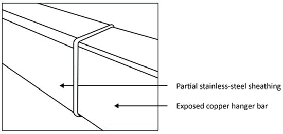
Figure 6.
Partially sheathed stainless-steel hanger bar design with exposed copper edges (From [21] in Proceedings of the Base Metals Conference with permission of the Southern African Institute of Mining and Metallurgy).
A fully sheathed permanent cathode hanger-bar design is made by Metso Outotec, formerly known as the Outokumpu permanent cathode (Figure 7). This cathode hanger bar contains a large solid copper cross-sectional core that is fully covered and placed into a rectangular stainless-steel tube of ~3 mm thickness [20]. The copper exposed towards the ends is minimal, allowing only the machined-out portion to make contact with the busbar. The hanger bar and cathode plate are laser-welded. An advantage of the Outokumpu design is its high corrosion resistance [21,22]. The laser weld eliminates the possibility of galvanic corrosion between the stainless-steel hanger bar and stainless-steel cathode blade by fusing the two metal components into a single, unified piece, creating a homogeneous, continuous connection that eliminates the dissimilar metal contact. Furthermore, laser welding creates a very localized heat-affected zone, leading to a homogeneous microstructure in the weld area, which minimizes the potential for localized corrosion cells. The continuous nature of the laser weld also prevents moisture and other corrosive substances from penetrating the joint and reaching the interface between the two components, which prevents the electrolyte from completing the circuit, necessary for galvanic corrosion to occur.
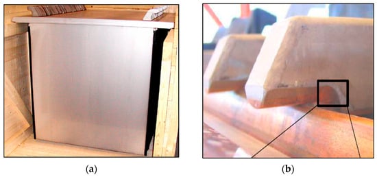
Figure 7.
(a) Outokumpu stainless-steel permanent cathode with fully sheathed hanger bar design (Reproduced from [22] in Proceedings of the Third Southern African Conference on Base Metals with permission of the Southern African Institute of Mining and Metallurgy). (b) Outokumpu fully sheathed hanger bar with exposed copper end portion making contact with busbar. (Reproduced from [21] in Proceedings of the Base Metals Conference with permission of the Southern African Institute of Mining and Metallurgy).
Glencore Technologies also introduced a modified cathode hanger bar design, known as the ‘steerhorn’ variant. This design reduces the distance that current is required to travel from the cathode blade to the hanger bar (Figure 8). Savings in power consumption of up to 2% are claimed, relative to traditional straight hanger bars [23].
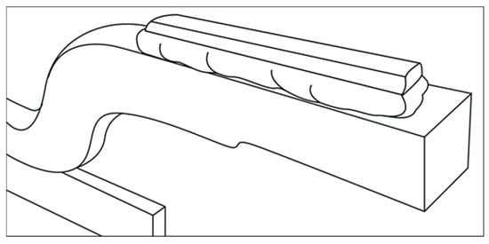
Figure 8.
ISAKIDD cathode with steerhorn hanger bar design (Adapted from [23] with permission from Glencore Technology).
3.2. Alternative Blank Materials
The most common material used for the cathode blade is austenitic stainless steel of 316L grade. Key constituents of conventional 316L stainless steel include 10%–14% Ni and 2%–3% Mo [16]. Uses of alternative stainless steels for the cathode blade have been investigated due to increasing metal prices and the need for a lower-cost cathode with a longer operating life. In a bid to reduce capital cost without compromising cathode quality and durability, a duplex stainless steel, LDX 2101, and standard 304L stainless steel were tested for this application. LDX 2101 is a low-alloyed duplex steel containing ~21.5% Cr, with only about 1.5% Ni and 0.3% Mo [17]. The LDX 2101 duplex stainless steel and the standard 304L stainless steel variants are well documented by Eastwood et al. [16] in terms of chemical resistance testing, strength, and operational testing. The reported results were promising, offering the possibility of considerably reducing the price of cathodes, and have been implemented at several sites. Duplex plates can be flexed more before reaching permanent deformation (i.e., have a higher yield strength) [24], therefore offering benefits for automated stripping and allowing the use of thinner plates. Duplex steels are also reported to offer better corrosion resistance in high-chloride environments [23,24], although South American operations that contain >30 mg/L Cl in their electrolytes all use 316L stainless steel for their permanent cathodes [6].
More recently, a modified austenitic stainless steel, 316plus, has been shown to demonstrate better mechanical strength and chloride-pitting resistance than 316L [23,24], in addition to significantly reduced plastic deformation, trending closer to LDX 2101 in durability. These innovations in construction materials enable cathode plates to withstand increasing mechanical stresses and extend operational life, while reducing maintenance frequency and the associated costs [23].
Depending on the steel grade (austenitic or duplex), cathode plates can be delivered with either a 2B or 2E surface finish. Both materials are cold rolled then heat treated: the 2B surface finish is pickled and passivated, resulting in a smooth surface with microscopically visible etched grain boundaries; the 2E finish is mechanically descaled [25]. The blade surface characteristics are important in ensuring adherence of the copper deposit throughout the electrodeposition cycle while maintaining clean stripping characteristics. Adhesion generally increases with increased surface roughness (Ra), although surface topography also plays a role [25]. Austenitic stainless steels have a 2B finish with a specific roughness of 0.2–0.3 µm Ra; duplex steels have a 2E finish with a surface roughness of 0.8–1.6 μm [25]. Both are successfully used in practice, depending on site preferences for initial higher capital costs or longer-term higher operating costs.
Zhang and Wu [26] documented the development of permanent stainless-steel cathodes in China, indicating that numerous types of stainless steels are available and used where applications are primarily dictated by the corrosivity of the working environment. These austenitic and duplex stainless steels contain varying levels of alloying elements. These authors report that the popularity of duplex stainless steels has increased in recent years [26].
3.3. Permanent Cathode Edge Strip Development
A prerequisite for the use of permanent cathode technology, regardless of design, is the use of edging or an edge strip on the blade of the cathode blank. The primary purpose of edge strips, which are generally applied on the sides and bottom edge of the cathode blades, is to prevent deposition of metal around the cathode blank [21]. Once metal has encapsulated the blank, stripping activities become extremely difficult, even for automated equipment. In all applications, it is important that edge strips are designed to be long enough along the side edge of the blank to protrude above the electrolyte solution level of the cell. Any electrolyte present between edge strip and cathode blank will result in metal deposition, which will lead to difficulty in stripping or damage to the applied edge strip in its entirety [27].
The lifespan of edge strips is largely related to mechanical issues and physical damage that can occur in operation, specifically related to electrode handling, the stripping machine design and method, manual stripping in the event of stripping machine breakdown, plating characteristics (e.g., significantly larger anodes compared with cathodes, leading to excessive plating and current density towards the edges), deterioration of the cathode blade and edge-strip attachment mechanism, the construction material, and compatibility with electrolyte temperature and composition.
Various types of edge strips are available on the market to increase the lifecycle of a cathode blank, including removable strips and permanently applied strips. During the cathode stripping process, the blank and edge strips endure repeated mechanical forces to loosen the deposited metal, which often damage the edge strip [21]. Removable edge strips, if not applied correctly and coupled with solution ingress, tend to come off during stripping activities. Operators need to reapply strips to the cathodes, which can be time-consuming and detrimental to higher-current-density processes if cathode replacement post-harvesting is not timeous. As noted by Beukes and Badenhorst [27], solution ingress between a cathode and permanent edge strip damages the edge strip over time, leading to premature failure.
Many geometries and construction materials have been used in a bid to increase edge strip lifetime. Metso Outotec pioneered significant innovative manufacturing developments, from their first-generation atmospheric low-pressure extrusion process to the second-generation high-pressure moulding technology, with commercial availability of the edge-strip manufacturing process in 2009 [21]. A wide range of plastic materials and polymers, such as high-density polyethylene, chlorinated polyvinyl chloride, acrylonitrile butadiene styrene, and modified polypropylene materials can be used [21]. The robust performance of the second-generation permanent edging process and its resilience to damage by stripping machines and related cathode handling reduced the frequency of replacement and reportedly increased the life cycle of edge strips from 1–2 years to more than 4 years [21].
Various edge strip designs were trialled during commissioning of the world’s first full-deposit nickel electrowinning plant, which uses stainless-steel permanent cathodes, at Rustenburg Base Metal Refiners, South Africa [28]. Several of these did not perform during blank flexing in the automated stripping process, resulting in difficulty in stripping, which led to an increase in manual stripping activities and damage to blanks, and caused the tankhouse to become a bottleneck to the refinery. Cross-slot and clip-on edge strips separated during the stripping process. The initial high-density polyethylene specifications and low-pressure extrusion process used were highly operator-dependent, which increased the likelihood of quality issues. A different type of polypropylene with an improved tensile and flexural strength, coupled with the use of perforated blanks, is now used in conjunction with the automated second-generation Outotec moulding process, which gives an edge strip lifetime exceeding one year [28].
3.4. Permanent Cathode Maintenance and Extending Cathode Life
An important consideration in the implementation of permanent cathode technology is the associated maintenance. Throughout the lifecycle of a permanent cathode, minor and major repairs may be deemed necessary due to the operational environment, conditions, and practice in which the cathodes are being used. Maintenance is required to ensure efficiency of the technology and prolong the lifespan to maximize the return on capital spent and reduce operational costs. Constant wear and tear is inevitable: if maintenance is avoided or delayed, challenges relating to processing and cathode stripping can rapidly become apparent [29]. As outlined by Marsden and Jickling [20], the electrical resistance, corrosion resistance, and durability of a permanent stainless-steel cathode deteriorate over time from the initial manufactured condition. Electrical resistance is expected to increase with time and is affected by several factors, one of which is dissolution of copper from the hanger bars due to the highly acidic operational environment. The poor corrosion resistance of the blank (in the form of pitting caused by high levels of chloride (>40 mg/L) in the electrolyte), the dissolution of copper hanger bars due to operational and chemical factors, and the use of dissimilar metals for cathode designs (either in the initial manufacturing or later when they come into contact) add to the potential for corrosion of stainless-steel cathodes. This shortens the life span and necessitates more frequent refurbishment due to pitting, galvanic corrosion, and blank deformities [20]. Physical handling of the cathodes and the inherent nature of the process contribute to reduced durability over time. Further factors that affect cathode durability include excessive loads on the hanger bars as a result of overplating, excessive force and stresses applied by stripping machines, abrasion of hanger bars by crane bailers and conveyors, and over-flexing of the cathode sheets during stripping [20]. Through these activities, the durability, dimensional stability, and verticality of cathodes are affected, and they become prone to rejection for re-use within the electrowinning cells.
Typical repairs that are required to ensure sustainability of the cathodes include the replacement of edge strips, repair of scratches on the cathode blade, straightening of bent sheets and hanger bars, and cleaning of ‘sticky’ residual copper from the blade [20]. Other operational issues requiring repair can include broken edge strips, poor electrical contact, severely bent cathodes, excessive hanger bar corrosion, compromised hanger bar welding, damaged V-grooves, and poor cathode adhesion to the blade surface [29]. The choice of which maintenance activities to undertake, and their frequency, is an operational decision, generally made based on the related costs and running strategy and whether the maintenance services are carried out in-house or are outsourced. In-house maintenance workshops typically manage edge-strip removal and installation, employ cathode-straightening machinery/equipment and cathode surface-cleaning tools (buffing machine or grinder), and have sufficient storage space for ready-to-use blanks. Off-site maintenance solutions synonymous with cathode suppliers are generally used for more severe issues, such as damage to the hanger bar or the cathode blade itself. These more complex tasks require additional machinery, such as a plate-straightening roller, V-groove renewal machine, or plate and hanger bar replacement machines [22].
More recent developments by original equipment manufacturers have enabled automated innovations that integrate key maintenance activities with cathode-stripping machines [21]. Stripping machines are typically designed for the ‘worst case scenario’—the ability to strip hard-to-strip copper. Designs include a reject cathode rack (cathodes containing thin copper, sticky copper, deformed blanks, etc.) with selection logic derived from camera recognition and/or robotics or physical measurements. Faulty cathode blanks are rejected and removed from the main production line and automatically diverted to a separate maintenance area for a quick turnaround, which reduces the number of required operators. Use of robotics in such systems has resulted in flexibility, better safety, and improved material handling.
The life expectancy of standard ISAKIDD process cathodes can reach 10 years without any repair, compared with less than three years for some other cathode designs [12]. Retaining the condition of the cathode blade is highly dependent on tankhouse management and practice. The life of permanent cathodes can be extended by several years by implementation of good housekeeping and maintenance strategies that support enhanced tankhouse process performance and efficiency [21].
4. Industrial Adoption of Permanent Cathodes in Copper Electrowinning
Figure 9 shows selected trends in the adoption of permanent cathode technology from 1999 to 2025, based on operational data collected from global copper electrowinning tankhouse surveys for this period [6,30,31,32,33,34,35]. These data typically represent approximately 40%–50% of world hydrometallurgical copper cathode production; as such, they can be considered indicative of the major industry trends. As shown by comparison of the data in Figure 9a,b, some 20% of surveyed tankhouses still use starter sheets today; however, these are all old tankhouses (commissioned in the 20th century) and contribute a relatively small proportion (<6%) of total survey production. Titanium cathode blanks were employed by two small (<10 kt/a Cu) operations in the 1990s for a short period, but these were never widely adopted owing to their high cost. All new and refurbished tankhouses today employ stainless- or duplex-steel cathode blanks. A wide range of suppliers and designs are now available, in addition to the ISAKIDD and Metso Outotec processes.
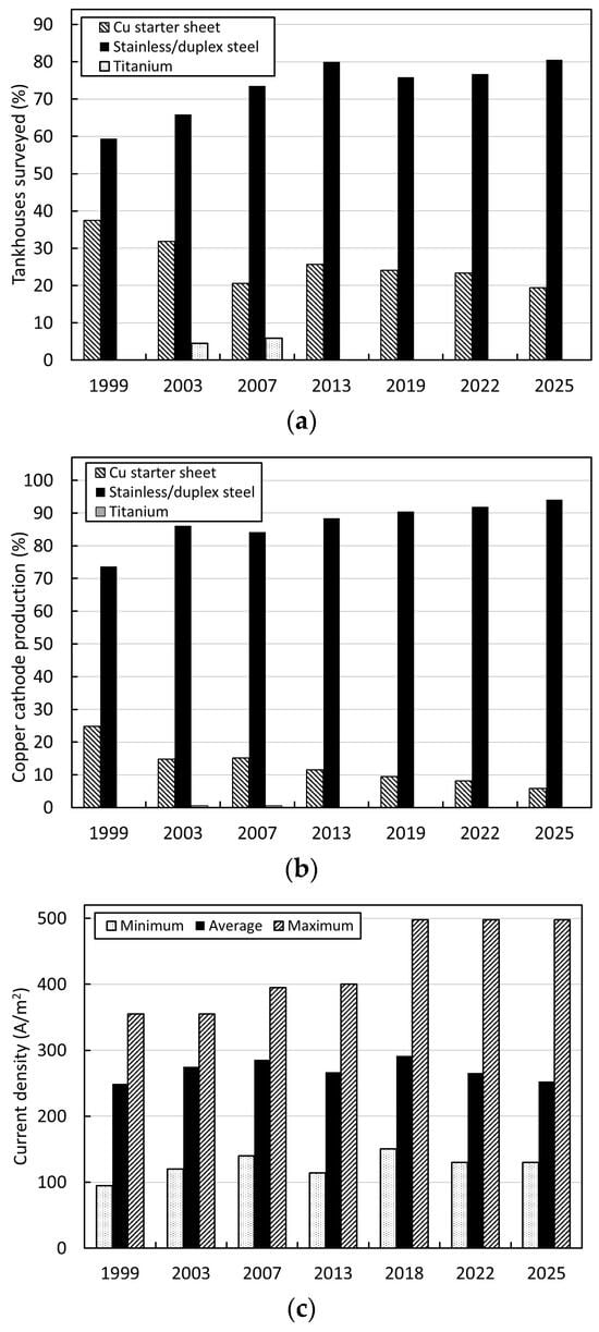
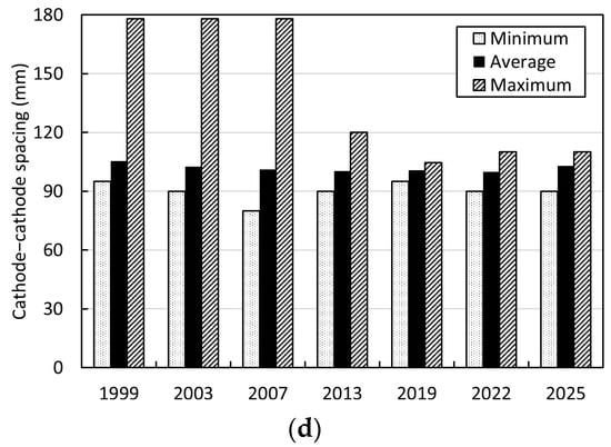
Figure 9.
Global copper electrowinning tankhouse survey data from 1999 to 2025 showing trends in (a) number of tankhouses using permanent cathode technology compared with starter sheets and alternatives, (b) copper cathode production by cathode technology, (c) cathode current density, and (d) cathode–cathode spacing (raw data taken from [6,30,31,32,33,34,35]).
Figure 9c indicates the corresponding trend towards the use of higher cathode current density over this period. Figure 9d shows the impact of adoption of this technology in enabling a reduction in electrode spacing, and the corresponding reduction in tankhouse footprint. Permanent cathode technology therefore aids in increasing refining intensity and productivity and improving electrode alignment to eliminate the likelihood of short circuits. Furthermore, permanent cathode technology enables a significant level of automation and robotics, in the form of cathode-stripping machines and associated electrode-handling activities, to limit manually intensive work and operator–equipment interactions, thereby significantly contributing to risk reduction in the tankhouse.
5. Conclusions
All greenfields copper electrowinning tankhouses constructed today, as well as tankhouse upgrades, employ permanent cathode technology with a preference for cathode starter sheets. This trend is expected to continue. In addition to providing a considerably safer working environment, with reduced human–equipment interaction, this technology offers significant benefits for process intensification in terms of a higher current density and reduced inter-electrode spacing, as well as a reduced power consumption and higher current efficiency owing to the minimization of short circuits due to the improved straightness, rigidity, and verticality of the cathode plates. This technology further enables a tankhouse to consistently produce copper sheets with excellent surface morphology, and contributes to high chemical purity of the cathode product. Permanent cathode tankhouses today consistently produce LME Grade A copper [35]. Advanced process control and automation and the ability to implement robotic operations are facilitated by the use of permanent cathode technology.
Author Contributions
Investigation, K.N. and K.C.S.; writing—original draft preparation, K.N.; writing—review and editing, K.C.S.; supervision, K.C.S. All authors have read and agreed to the published version of the manuscript.
Funding
This research received no external funding.
Data Availability Statement
The data presented in Section 4 are available on request from the corresponding author.
Acknowledgments
Support from the management of Rustenburg Base Metals Refiners and Valterra Platinum in carrying out this review and permitting publication is gratefully acknowledged.
Conflicts of Interest
Author Kalin Naidoo is employed by the company Valterra Platinum. The other author declares that the research was conducted in the absence of any commercial or financial relationships that could be construed as a potential conflict of interest.
References
- Copper Worldwide. Map and directory. Copp. Worldw. 2024, 14, Directory Pullout i1–i12. [Google Scholar]
- International Copper Study Group. The World Copper Factbook 2024; International Copper Study Group: Lisbon, Portugal, 2024; p. 14. [Google Scholar]
- Wood Mackenzie. Global Copper SX-EW Production; Wood Mackenzie: Edinburgh, UK, 2024. [Google Scholar]
- Schlesinger, M.E.; Sole, K.C.; Davenport, W.G.; Flores, G.R.A. Extractive Metallurgy of Copper, 6th ed.; Elsevier: Amsterdam, The Netherlands, 2021; pp. 437–465. [Google Scholar]
- London Metal Exchange. Special Contract Rules for Copper Grade A. Available online: https://www.lme.com/en/physical-services/brands/chemical-composition (accessed on 13 May 2024).
- Sole, K.C.; Moats, M.S.; Lillo, A.; Steeples, J.; Yañez, H.; Parker, J. Copper electrowinning: 2022 global survey of tankhouse operating practice and performance. In Proceedings of the Copper 2022 International Conference, Santiago, Chile, 13–17 November 2022; Gecamin: Santiago, Chile, 2022; pp. 28–39. [Google Scholar]
- Free, M.; Moats, M.; Robinson, T.; Neelameggham, N.; Houlachi, G.; Ginatta, M.; Creber, D.; Holywell, G. Electrometallurgy now and in the future. In Proceedings of the Electrometallurgy 2012, Orlando, FL, USA, 11–15 March 2012; The Minerals, Metals and Materials Society: Warrendale, PA, USA, 2012; pp. 1–27. [Google Scholar]
- Nicol, M.J. Hydrometallurgy Volume 2: Practice; Elsevier: Amsterdam, The Netherlands, 2022. [Google Scholar]
- Armstrong, W. The ISA Process and its contribution to electrolytic copper. In Proceedings of the Rautomead Conference, Scotland, UK, August 1999; Available online: https://www.glencoretechnology.com/.rest/api/v1/documents/8858ecf6a65c16329038ee5f5cfc063d/The+Isa+Process+and+its+Contribution+to+Electrolytic+Copper.pdf (accessed on 8 October 2024).
- Perry, I.J. Cathode for Use in the Electrolytic Refining of Copper. Australia Patent Application 10927, 20 August 1980. [Google Scholar]
- Lawson, V.; Dewaal, H.; Heferen, G.; Aslin, N.; Voigt, P.; Hourn, M. Mount Isa Mines: Necessity driving innovation. In Proceedings of the 50th Annual Canadian Mineral Processors Conference, Ottawa, ON, Canada, 23–25 January 2018; Canadian Institute of Mining, Metallurgy and Petroleum: Montreal, QC, Canada, 2018; pp. 23–25. [Google Scholar]
- Weston, J.; Webb, W. The link between operating practice and maximising the life of stainless steel electrodes in electrowinning and electrorefining operations. In Proceedings of the Copper 2003 5th International Conference, Santiago, Chile, 30 November–3 December 2003; Canadian Institute of Mining, Metallurgy and Petroleum: Montreal, Canada, 2003; Volume 5, pp. 151–164. [Google Scholar]
- Naidoo, K.; Pelser, M.; Hagemann, J.; Sole, K.C. Improving performance at Rustenburg Base Metals Refiners copper tankhouse: Operational review and embracing fundamentals. J. S. Afr. Inst. Min. Metall. 2025, 125, 307–316. [Google Scholar] [CrossRef]
- Aslin, N.; Stone, D.; Webb, W. Current Distribution in Modern Copper Refining, 2005. Available online: https://www.glencoretechnology.com/.rest/api/v1/documents/41037d647e29db4dcb9932ac302a59d6/2020+ISAKIDD+Compendium+of+Papers.pdf?download=true (accessed on 12 June 2025).
- Webb, W.; Weston, J. The Development of a “Lower Resistance Permanent Cathode”. Minera Chilena (March April) 2003. Available online: https://www.glencoretechnology.com/.rest/api/v1/documents/41037d647e29db4dcb9932ac302a59d6/2020+ISAKIDD+Compendium+of+Papers.pdf?download=true (accessed on 12 June 2025).
- Eastwood, K.; Whebell, G.; Street, H. Developments in permanent stainless steel cathodes within the copper industry. In Proceedings of the Copper 2007 International Conference, Toronto, ON, Canada, 25–30 August 2007; Canadian Institute of Mining, Metallurgy and Petroleum: Montreal, QC, Canada, 2007; Volume 5, pp. 35–46. [Google Scholar]
- Donaldson, P.; Detulleo, J. Falconbridge’s Kidd Copper Refinery—Birthplace of the Kidd Process: An update on the refinery, and the latest developments in the Kidd Process. In Proceedings of the Copper 2003, Santiago, Chile, 30 November–3 December 2003; Canadian Institute of Mining, Metallurgy and Petroleum: Montreal, QC, Canada, 2003; Volume 5, pp. 165–174. [Google Scholar]
- Aslin, N.; Eriksson, O.; Heferen, G.; Yek, G.S. Developments in cathode stripping machines-an integrated approach for improved efficiency. In Proceedings of the Copper 2010 International Conference, Electrowinning and Electrorefining, Hamburg, Germany, 6–10 June 2010; Gesellschaft der Metallurgen und Bergleute: Clausthal-Zellerfeld, Germany, 2010; Volume IV, pp. 1253–1270. [Google Scholar]
- Chooye, M.; Patel, R.; Pranowo, A.; O’Rourke, B. Copper refinery modernisation, Mopani Copper Mines Plc, Mufulira, Zambia. In Proceedings of the Copper Cobalt Africa 2018, Livingstone, Zambia, 9–12 July 2018; Southern African Institute of Mining and Metallurgy: Johannesburg, South Africa, 2018; pp. 385–394. Available online: https://www.saimm.co.za/Conferences/Copper-Cobalt-2018/39-ORourke-385-394.pdf (accessed on 5 May 2024).
- Marsden, T.; Jickling, J. The next generation of permanent cathode and lead anode technology. In Proceedings of the Hydrometallurgy Conference, Muldersdrift, South Africa, 24–26 February 2009; Southern African Institute of Mining and Metallurgy: Johannesburg, South Africa, 2009; pp. 249–256. [Google Scholar]
- Nordlund, L.; Virtanen, H. Development of permanent cathode technology and related lifecycle solutions. In Proceedings of the Base Metals Conference, White River, South Africa, 2–4 September 2013; Southern African Institute of Mining and Metallurgy: Johannesburg, South Africa, 2013; pp. 89–98. Available online: https://www.saimm.co.za/Conferences/BM2013/089-Nordlund.pdf (accessed on 10 May 2024).
- Kuusisto, R.; Pekkala, P.; Karcas, G.J. Outokumpu SXEW technology package. In Proceedings of the Third Southern African Conference on Base Metals, Kitwe, Zambia, 26–29 June 2005; South African Institute of Mining and Metallurgy: Johannesburg, South Africa, 2005; pp. 26–29. Available online: https://www.saimm.co.za/Conferences/BM2005/321-336_Kuusisto.pdf (accessed on 10 June 2024).
- Glencore Technologies. ISAKIDD™ Cathode Plates and Handling Equipment Deliver the Best Fit for Purpose in the Real World. Available online: https://www.glencoretechnology.com (accessed on 2 February 2024).
- Spencer, A.D.; Pranowo, A.; Eriksson, P.O.; McNally, M. Recent advances in ISAKIDD cathode design and cathode stripping machines. In Proceedings of the Copper 2025, Phoenix, AZ, USA, 16–20 November 2025; Canadian Institute of Mining, Metallurgy and Petroleum: Montreal, ON, Canada, 2025. in press. [Google Scholar]
- Granqvist, J.; Palosaari, M.; Koivisto, E. New stainless steel solutions as permanent cathode plate materials for tank houses. In Proceedings of the Copper 2022, Santiago, Chile, 13–17 November 2022; Gecamin: Santiago, Chile, 2022; pp. 105–116. [Google Scholar]
- Zhang, C.; Wu, J. Development of permanent stainless steel cathodes in China. In Proceedings of the XXVIII International Mineral Processing Congress, Quebec City, QC, Canada, 11–15 September 2016; Canadian Institute of Mining, Metallurgy and Petroleum: Montreal, ON, Canada, 2016; pp. 1559–1569. [Google Scholar]
- Beukes, N.; Badenhorst, J. Copper electrowinning: Theoretical and practical design. J. S. Afr. Inst. Min. Metall. 2009, 109, 343–356. Available online: https://www.saimm.co.za/Journal/v109n06p343.pdf (accessed on 26 March 2024).
- Hagemann, J.P.; Ndlovu, J.; Nelson, L.R.; Bryson, L.J.; Gilmore, M.W.; Hines, K.; Peyper, B.; Varty, R.N.; Sepoloane, T. Full deposit nickel electrowinning at Rustenburg Base Metal Refiners. In Proceedings of the XXCIII International Mineral Processing Congress Proceedings (IMPC 2016), Quebec City, QC, Canada, 11–15 September 2016; Canadian Institute of Mining, Metallurgy and Petroleum: Montreal, ON, Canada, 2016; pp. 1–13. [Google Scholar]
- Nordlund, L.; van der Walt, H. Advances in permanent cathode maintenance solutions. In Proceedings of the Copper Cobalt Africa, incorporating the 9th Southern African Base Metals Conference, Livingstone, Zambia, 9–12 July 2018; Southern African Institute of Mining and Metallurgy: Johannesburg, South Africa, 2018; pp. 395–406. Available online: https://www.saimm.co.za/Conferences/Copper-Cobalt-2018/40-Norlund-395-406.pdf (accessed on 30 March 2024).
- Jenkins, J.; Davenport, W.G.; Kennedy, B.; Robinson, T. Electrolytic copper leach, solvent extraction and electrowinning world operating data. In Proceedings of the Copper ‘99, Hydrometallurgy of Copper, Phoenix, AZ, USA, 10–13 October 1999; The Minerals, Metals and Materials Society: Warrendale, PA USA, 1999; Volume 4, pp. 493–566. [Google Scholar]
- Robinson, T.; Davenport, W.G.; Jenkins, J.; King, M.; Rasmussen, S. Electrolytic copper electrowinning–2003 world tankhouse operating data. In Proceedings of the Copper 2003, Santiago, Chile, 30 November–3 December 2003; Canadian Institute of Mining, Metallurgy and Petroleum: Montreal, ON, Canada, 2003; Volume V, pp. 3–66. [Google Scholar]
- Robinson, T.; Davenport, W.; Moats, M.; Karcas, G.; Demetrio, S. Electrolytic copper electrowinning–world tankhouse operating data 2007. In Proceedings of the Copper 2007, Copper Electrorefining and Electrowinning, Toronto, ON, Canada, 25–30 August 2007; Canadian Institute of Mining, Metallurgy and Petroleum: Montreal, ON, Canada, 2007; Volume V, pp. 375–423. [Google Scholar]
- Robinson, T.; Sole, K.C.; Sandoval, S.; Moats, M.; Siegmund, A.; Davenport, W. Copper electrowinning: 2013 world tankhouse operating data. In Proceedings of the Copper 2013 International Conference, Santiago, Chile, 1–4 December 2013; Gecamin: Santiago, Chile, 2013; Volume 5, pp. 3–14. [Google Scholar]
- Sole, K.C.; Moats, M.S.; Sandoval, S.; Robinson, T.G.; Davenport, W.E. Copper electrowinning: 2018 global survey of tankhouse operating practice and performance. In Proceedings of the Copper 2019, Vancouver, BC, Canada, 18–21 August 2019; Canadian Institute of Mining, Metallurgy and Petroleum: Montreal, ON, Canada, 2019. Paper 581092. [Google Scholar]
- Sole, K.C.; McCullum, T.; Nisbett, A.; Steeples, J.; Moats, M.S. Copper electrowinning: 2025 global survey of tankhouse operating practice and performance. In Proceedings of the Copper 2025, Phoenix, AZ, USA, 16–20 November 2025; Canadian Institute of Mining, Metallurgy and Petroleum: Montreal, ON, Canada, 2025. in press. [Google Scholar]
Disclaimer/Publisher’s Note: The statements, opinions and data contained in all publications are solely those of the individual author(s) and contributor(s) and not of MDPI and/or the editor(s). MDPI and/or the editor(s) disclaim responsibility for any injury to people or property resulting from any ideas, methods, instructions or products referred to in the content. |
© 2025 by the authors. Licensee MDPI, Basel, Switzerland. This article is an open access article distributed under the terms and conditions of the Creative Commons Attribution (CC BY) license (https://creativecommons.org/licenses/by/4.0/).