Abstract
The vast majority of current research on hydrocyclone field centrifugal separation focuses on low concentration fluids having volume fraction less than 3%. For high-concentration fluids having volume fractions greater than 10%, which are often encountered in engineering, the law governing particle motion and the classification mechanism are still unclear. In order to gain insights into the interaction between fine particles in the high concentration hydrocyclone field and to improve the hydrocyclone separation performance of these particles, a Dense Discrete Phase Model (DDPM) of the Euler-Eulerian method under the Ansys Fluent 14.5 software was employed. Numerical simulations were carried out to study the characteristics of the hydrocyclone field of dense particles and the influence of parameters, such as the diameter of the overflow outlet, diameter of the underflow outlet, and material concentration, on separation performance. The trajectories and separation efficiencies of two kinds of fine particles with different densities and six different particle sizes at high concentration were obtained. The results show that for the hydrocyclone classification of high-concentration fine particles, particles with large density and small particle size are more likely to enter the internal cyclone and discharge from the overflow. Particles with small density and large particle size are more likely to enter the external cyclone and discharge from the underflow. The research results of this topic could provide a feasible reference and theoretical basis for the centrifugal separation of high-concentration fine particle fluid.
1. Introduction
Discarded drilling mud contains a large amount of the valuable mineral barite. In order to recover barite, it is necessary to remove impurities such as rock debris from the mud. However, due to the small mud particle size (less than 74 μm) and high concentration (mass concentration greater than 50%), the conventional hydrocyclone has a poor separation effect on high-concentration fine particles. Considering the fine grain size, high viscosity of slurry, and difficulty in separating the barite and impurities, the author designed a Φ20 mm, small diameter and long cone hydrocyclone group. Due to its small diameter, the centrifugal strength is large and the cut-size is small, while the long cone causes particles stay in the hydrocyclone for a long time and become completely separated. When the waste slurry containing barite enters the hydrocyclone group of Φ20 mm, the barite is enriched from the underflow of the hydrocyclone group under the action of centrifugal force, and impurities such as rock debris are discharged from the overflow of the hydrocyclone group, thereby the separation of the barite from the impurity phase is achieved.
However, due to the many parameters that affect the performance of hydrocyclone separation (such as structural parameters and operating parameters) [1,2,3,4], in order to obtain the influence of these parameters on the flow field characteristics and the separation effect, a large number of experiments are required. With the development of computational fluid dynamics (CFD), numerical simulation methods have been widely recognized by researchers [5,6,7,8]. By simulating the flow field, the rules that affect the flow field and separation characteristics can be determined, which provides a theoretical basis for optimizing the structural parameters and operating parameters of the hydrocyclone. The literature on the simulation of the hydrocyclone flow field based on CFD technology covers the exploration of the internal hydrocyclone flow field [9,10,11,12], optimization of the structure to improve the separation performance [13,14,15], formation mechanism of the air column, and influence of the air column on the flow field [16,17,18]. In terms of flow field simulation, most scholars agree to use the Reynolds stress model (RSM) [19,20] to treat the turbulent state in the hydrocyclone and use the volume of fluid (VOF) model [21,22] to treat the gas-liquid contact surface. The particle migration motion can be treated by the discrete phase model (DPM) in the Lagrangian method [23,24]. Through a large number of literature reviews, it can be found that the separation characteristics of the hydrocyclone can be described by the above model, which has been unanimously recognized by researchers.
However, the results obtained so far are for low-concentration fluids (volume fractions less than 3%), which are rare in engineering practice. The high-concentration fluids (volume fractions greater than 10%) often encountered in engineering are very different from sparse particulate fluids. Its remarkable characteristics are: high particle volume concentration, frequent contact collision between particles, and strong interaction between particles and fluid. Due to the complex interaction between the particles, and between particles and fluids, the mechanism of high-concentration slurry classification is still unclear. DPM ignores the interaction between particle phases and can be used to describe the movement of particles in a system with a lower concentration [25,26]. Theoretically, the Mixture model and Euler-Euler model can be used to simulate high-concentration systems, but the mixture model and Euler-Euler model assume that the particles are continuous and uniform, and the collision between particles is ignored. This is inconsistent with the description of the inhomogeneity of the particle fluid system in the hydrocyclone, so it is difficult to understand and describe the separation process of the particles in the hydrocyclone [27,28]. The discrete element method (DEM) is considered to be a powerful tool for the study of particle-fluid systems. Many scholars have studied the interaction between particles and liquid flow, between the particles, and between particles and walls by the coupling of flow field and particles [29]. As can be seen from the literature, the DEM is a promising method. However, it searches for surrounding particles when dealing with particle collisions, which is time-consuming and computationally intensive.
The DDPM model is a simplified DEM model. Similar to DEM, this model takes into account the particle-particle collisions and porosity in the fluid motion equation. Besides, this model performs better than the DEM model in terms of the efficiency of calculating particle collisions. Therefore, based on the principle of hydrocyclone separation and combined with the multiphase flow theory, this work uses the DDPM in the Euler-Eulerian method to study the characteristics of the high-concentration flow field and the motion behavior of fine particles inside the hydrocyclone. The influence of structural parameters and operating parameters on the separation performance of hydrocyclones under high-concentration and fine-particle conditions is explored, which could provide a theoretical basis for optimizing the structural design of the hydrocyclone.
2. Materials and Methods
2.1. Hydrocyclone Geometry Model
This paper designs a Φ20mm diameter hydrocyclone. The feed inlet geometric shape is a rectangular tangential feed port, with dimensions of 4 mm × 6 mm. The cone angle is θ = 6°. The structural parameters of the hydrocyclone are shown in Table 1.

Table 1.
Specifications of the hydrocyclone used in this study.
The structure schematic of the hydrocyclone is shown in Figure 1. The direction in which the overflow outlet is located was defined as the positive direction of the z-axis, and the center point of the underflow outlet was defined as the origin. Two cross-sections of x = 0, y = 0, z = 100 mm and x = 0, y = 0, z = 140 mm in the hydrocyclone were selected as data analysis feature faces.
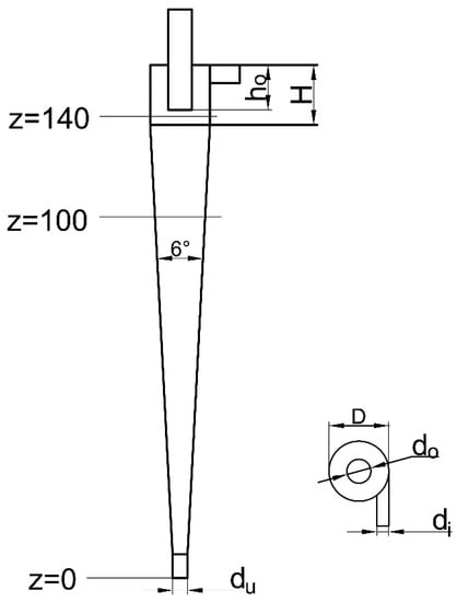
Figure 1.
Schematic diagram of the hydrocyclone.
2.2. Multiphase Flow Model
The DDPM in the Euler model combines the Eulerian model with the governing equations of the DPM model, eliminating the limitation of the discrete phase volume fractions and thus, can characterize dense discrete phase fluids. At the same time, the DDPM model considers the interaction between the particles, particles and walls, and thus, is closer to the actual movement of the particles [30]. In this study, the DDPM model under Ansys Fluent 14.5 software is used to simulate the high concentration particle system in the hydrocyclone.
2.3. Turbulence Model
The characteristics of fluid anisotropy inside the hydrocyclone are very obvious, and it belongs to the turbulent motion with rapid development and variations. The Reynolds stress model (RSM) considers the effects of buoyancy, shear force, pressure, etc. on turbulent flow, and can predict the internal conditions of the flow field with less error. In this study, the RSM model is used to simulate the anisotropic turbulent flow field in the hydrocyclone.
2.4. Discrete Format and Numerical Calculation of the Flow Field
The SIMPLE algorithm has great advantages in solving the incompressible flow field. Assumptions about the velocity field and pressure field can be made separately, and correct the calculated pressure field by using the solved velocity field according to the principle of mass conservation. The automatically corrected velocity field can be obtained by solving the current pressure, thus ensuring highly accurate results. The SIMPLE algorithm has many extensions applicable to multiphase flow. Among them, the phase coupled SIMPLE algorithm adopts the method of separation and solution, which is closer to the actual running state of the fluid [31]. This study adopts the phase coupled SIMPLE algorithm.
2.5. Hydrocyclone Meshing
The ICEM-CFD software (14.5) was used to mesh the hydrocyclone with hexahedral elements, and the mesh of the inlet and outlet side walls is refined to improve the simulation accuracy. The generated mesh of the hydrocyclone is shown in Figure 2, which has 65,994 elements.
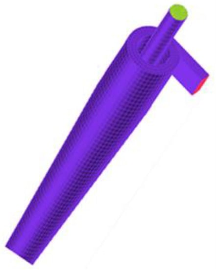
Figure 2.
Meshed geometry.
2.6. Boundary Conditions
- (1)
- Inlet boundary
Set the hydrocyclone inlet to the velocity inlet.
- (2)
- Outlet boundary
There are two outlets in the hydrocyclone, which are an overflow outlet and an underflow outlet, respectively. Both the overflow outlet and underflow outlet are set as pressure outlets with pressure set to zero.
- (3)
- Side wall boundary condition
During the operation of the hydrocyclone, the wall surface is stationary, and there is no exchange of matter and energy between the wall and the surrounding environment. The wall of the hydrocyclone is treated as a non-slip boundary condition and set to wall.
- (4)
- Discrete phase boundary condition
The solid phase particles in the drilling fluid mainly include rock debris impurities with a density of 2650 kg/m3 and barite with a density of 4300 kg/m3. The velocity of the particle phase is consistent with the continuous phase. The particles discharged from the overflow outlet are set to “escaped”, the particles discharged from the underflow outlet are set to “captured”, and the separation efficiency is calculated by tracking the number of escaped and captured particles. The wall boundary is set to “reflection”, assuming that the particles have no energy loss before and after the collision and the rebound coefficient is set to 1.
2.7. Experimental Method
The experimental system for recovering barite from drilling mud is shown in Figure 3. The experimental system is composed of hydrocyclone, centrifugal pump, pressure gauge, slurry tank, and blender. The feed pressure is controlled by adjusting the regulating valve, and the overflow and underflow samples are taken at the same time when the experimental system runs stably. The particle size composition of the feed material measured by the laser particle sizer is shown in Table 2.
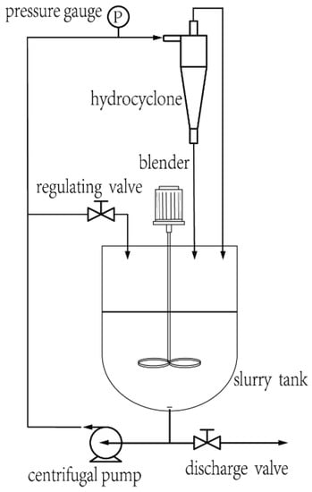
Figure 3.
The experimental system.
Table 2.
Particle Size Distribution.
3. Results and Discussions
3.1. Model Validation and Analysis
Figure 4 show a comparison of the experimental and numerical simulation results. It can be seen from the figure that their trends are basically the same. However, it should be noted that the prediction result of the numerical simulation for the separation efficiency is higher than that of the experiment, which leads to a larger prediction result for the cut-size and separation sharpness. In the experiment, due to the action of thickeners such as bentonite, the drilling mud showed non-Newtonian fluid characteristics.
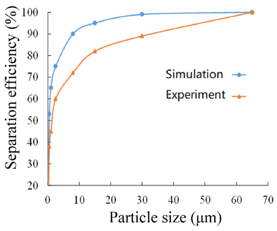
Figure 4.
Comparison of experimental and numerical simulation results.
3.2. Effect of Overflow Diameter on Separation Performance
Set the inlet speed to 15 m/s, select the bottom outlet diameter of 4 mm, and set the feed mass concentration to 66%. The diameters of the overflow outlets are selected as Φ6 mm, Φ7 mm, Φ8 mm, Φ9 mm, and Φ10 mm, respectively, to perform numerical simulation analysis of the flow field.
Figure 5 shows the static pressure distribution inside the hydrocyclone at different overflow diameters. It can be seen from the figure that the pressure in the hydrocyclone is distributed in a central symmetry state. The static pressure is highest at the wall surface position and gradually decreases from the wall surface to the center position in the radial direction. A negative pressure region is formed at the center position of the shaft. At both the cross-sections of z = 100 mm and z = 140 mm in the hydrocyclone, the value of pressure decreases as the diameter of the overflow increases. This shows that, as the diameter of the overflow increases, the strength of the internal vortex inside the hydrocyclone decreases, the internal energy consumption of the hydrocyclone decreases, and the overflow discharge resistance decreases. This indicates that the larger the overflow outlet, the better the discharge of materials with small density and fine particles.
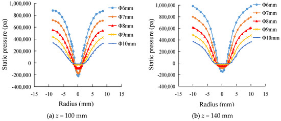
Figure 5.
Effect of overflow outlet diameter on static pressure. (a) z = 100 mm.(b) z = 140 mm.
Figure 6 shows the tangential velocity profile of fluid in the hydrocyclone. It can be seen from Figure 6 that the tangential velocity is M-shaped with the minimum tangential velocity recorded at the wall position. As the radius of rotation decreases, the tangential velocity gradually increases from the wall to the axis, and the tangential velocity reaches a maximum at the separation interface. Subsequently, the tangential velocity decreases rapidly as the radius of rotation decreases. At the same time, it can be observed that, as the diameter of the overflow increases, the tangential velocity decreases gradually. This indicates that as the diameter of the overflow increases, the area of the forced vortex at the center also increases gradually, which is beneficial to the improvement of the overflow yield.
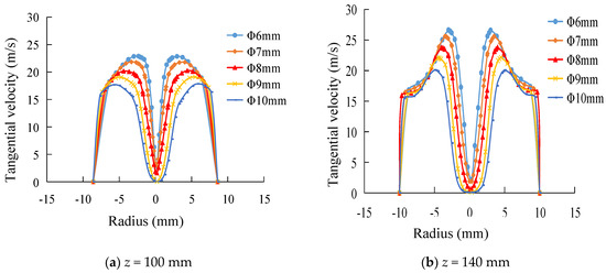
Figure 6.
Effect of overflow outlet diameter on tangential velocity. (a) z = 100 mm.(b) z = 140 mm.
Figure 7 shows the axial velocity profile of two different cross sections in the hydrocyclone. It can be seen from the figure that the axial velocity variation of the two cross sections is essentially the same. The axial velocity of the upward flowing fluid is greatly affected by the change in the diameter of the overflow outlet, which increases as the diameter of the overflow pipe increases. The axial velocity of the downward moving fluid is relatively unaffected by changes in the diameter of the overflow. At the same time, it can be seen that the extent of the forced vortex region at the center increases as the diameter of the overflow outlet increases. This suggests that as the diameter of the overflow increases, the flow rate of the upward moving material also increases.
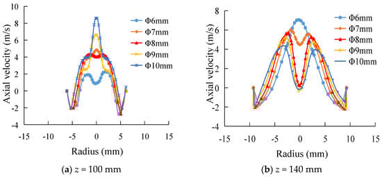
Figure 7.
Effect of overflow outlet diameter on axial velocity. (a) z = 100 mm.(b) z = 140 mm.
Figure 8 shows the effect of the change in the diameter of the overflow on the separation efficiency. It can be seen from the figure that, as the diameter of the overflow outlet increases, the separation efficiency of particles having different particle sizes decreases. When the diameter of the overflow outlet is increased to 10 mm, the separation efficiency of the hydrocyclone is minimized. When the diameter of the overflow outlet is 6 mm, the separation efficiency is the highest, indicating that the separation efficiency of barite can be improved by appropriately reducing the diameter of the overflow outlet. However, if the diameter of the overflow outlet is too small, the proportion of fine particles in the underflow will increase, and the phenomenon of the underflow carrying fine particles is promoted, thus lowering the separation accuracy.
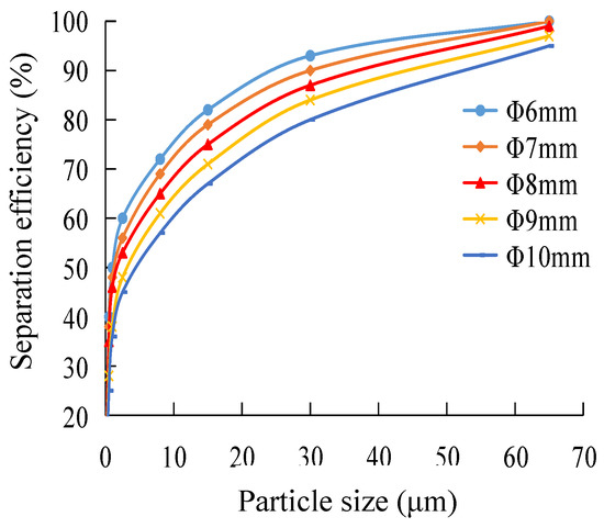
Figure 8.
Effect of overflow outlet diameter on separation efficiency.
3.3. Influence of Diameter of the Underflow Outlet on Separation Performance
The diameter of the underflow outlet is an important structural parameter of the hydrocyclone. Any change in the diameter of the underflow outlet will cause the shape of the air column of the hydrocyclone to change, which will have a great impact on the classification granularity. Therefore, it is necessary to study the influence of the diameter of the underflow on the flow field characteristics. Here, the drilling fluid mass concentration is set to 66%, inlet velocity to 15 m/s, and overflow diameter to Φ8 mm. The underflow outlet diameter is selected as Φ2 mm, Φ3 mm, Φ4 mm, and Φ5 mm, respectively, to simulate the flow field numerically. The separation performance of the hydrocyclone is explored by analyzing the changes in pressure and velocity inside the flow field.
The static pressure distribution in the hydrocyclone at different underflow outlet diameters is shown in Figure 9. It can be seen from the figure that the pressure inside the hydrocyclone decreases as the diameter of the underflow outlet increases, indicating that the centripetal force of the particles in the flow field is weakened with the increase in the diameter of the underflow outlet, and subsequently, the fluid entering the underflow will increase, which will cause the underflow yield also to increase. However, it also causes the fine particles, which should be discharged from the overflow outlet, to become mixed with the underflow, resulting in the deterioration of the classification accuracy.
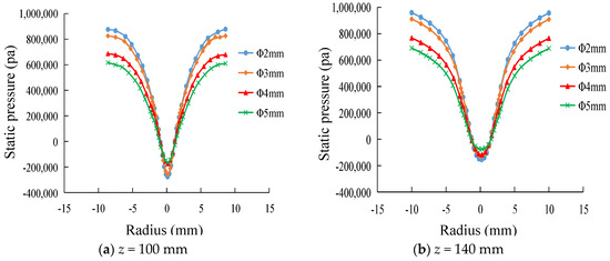
Figure 9.
Effect of underflow outlet diameter on static pressure. (a) z = 100 mm.(b) z = 140 mm.
Figure 10 is a tangential velocity distribution diagram of the hydrocyclone. It can be seen from the figure that the tangential velocity of the fluid gradually decreases as the diameter of the underflow outlet increases. As the diameter of the underflow outlet increases, the position of the maximum tangential velocity gradually shifts toward the center, causing the forced vortex region at the axial center to contract, and the free vortex region becomes larger, which affects the separation effect. Therefore, the selection of the diameter of the underflow outlet is directly related to the classification accuracy and classification efficiency. If the diameter of the underflow outlet is too large, the rate of discharge of the underflow will become large, and a low-density solid phase such as rock debris may be discharged from the underflow outlet, resulting in the underflow carrying fine particles. If the diameter of the underflow outlet is too small, the flow rate will decrease and some of the barite particles will escape through the overflow outlet, causing the overflow to carry coarse particles.
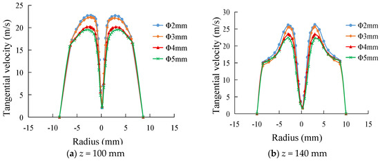
Figure 10.
Effect of underflow outlet diameter on tangential velocity. (a) z = 100 mm.(b) z = 140 mm.
Figure 11 is an axial velocity distribution diagram of different sections in the hydrocyclone. For a constant feed rate, the axial velocity decreases as the diameter of the underflow outlet increases. This shows that the power discharged by the fluid through the overflow outlet becomes smaller, which is not conducive to the separation of low density rock debris and high density barite.
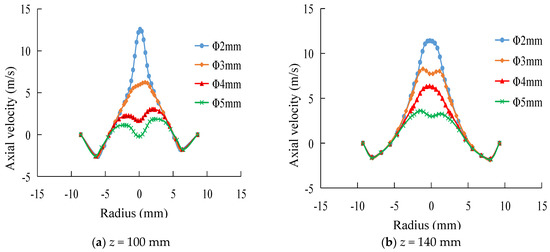
Figure 11.
Effect of underflow outlet diameter on axial velocity. (a) z = 100 mm.(b) z = 140 mm.
The influence of the diameter of the underflow outlet on the flow field is also reflected on the axial zero-speed envelope surface. Figure 12 compares the zero-velocity envelopes corresponding to the four underflow outlets. It can be seen from the figure that, as the diameter of the underflow outlet of the hydrocyclone increases, the axial zero-speed envelope surface begins to shrink. The area covered by the zero-speed envelope surface shrinks continuously, and the flow through the external hydrocyclone gradually increases, which causes the light-density solid phase such as rock debris to be discharged with the underflow, resulting in a decrease in classification accuracy.
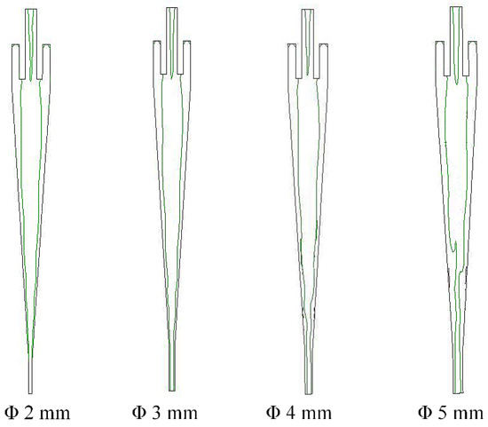
Figure 12.
The zero-velocity envelopes corresponding to the four underflow outlets.
Figure 13 shows the effect of the change in the diameter of the underflow outlet on the separation efficiency. As can be seen from the figure, the separation efficiency curve increases as the diameter of the underflow outlet increases. The reason is that as the diameter of the underflow outlet increases, a large amount of drilling fluid is discharged from the underflow outlet and the solid phase yield of the underflow is greatly improved, which results in an increase in the recovery rate of barite in the underflow. However, if the diameter of the underflow outlet is too large, the drilling fluid will also carry away a large quantity of low-density particles such as rock debris discharged from the underflow, resulting in the underflow carrying fine particles and a reduced separation accuracy.
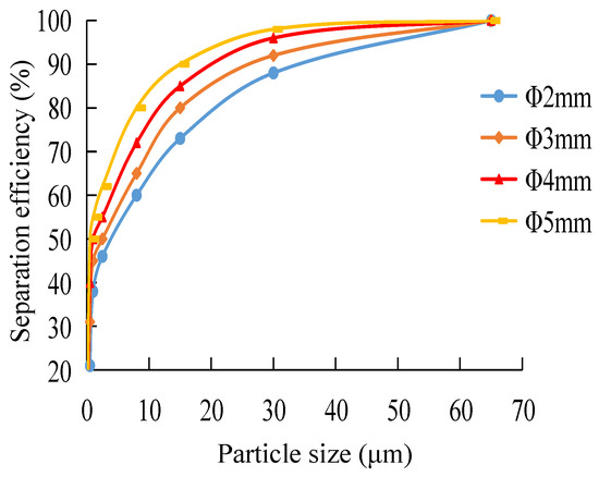
Figure 13.
Effect of underflow outlet diameter on separation efficiency.
3.4. Effect of Material Concentration on Separation Performance
Material concentration has a great influence on the separation performance of the hydrocyclone. The higher the concentration, the greater the viscosity of the material, and the harder it is to separate the low density rock debris from the high density barite. Therefore, it is necessary to explore the influence of material concentration on the separation performance of the hydrocyclone. Set the diameter of the underflow outlet to 4 mm, diameter of the overflow outlet to 6 mm, and the inlet speed to 15 m/s. The material mass concentration is set at 58%, 60%, 62%, 64%, and 66%, respectively.
Figure 14 shows the pressure distribution diagram of different cross sections in a hydrocyclone at different concentrations. It can be seen from the figure that as the material concentration increases, the internal pressure drop in the hydrocyclone gradually increases, and the radial pressure gradient gradually increases. This can be explained by the fact that when the concentration of the drilling fluid is low, the interaction force between the particles is small, and the particles of different sizes and densities are free to settle at different speeds. When the concentration of the drilling fluid is high, the interactions between particles and that between particles and fluid are large, causing the solid particles to be in an interference sedimentation state. The increased flow resistance of the medium prompts an increase in the energy consumed by particle separation in the flow field, causing the internal pressure drop of the hydrocyclone to increase as the concentration increases.
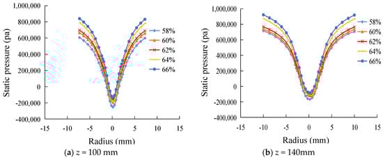
Figure 14.
Effect of concentrations on pressure distribution in the hydrocyclone. (a) z = 100 mm.(b) z = 140 mm.
Figure 15 is a graph showing the tangential velocity distribution of different sections in a hydrocyclone at different concentrations. It can be seen from the figure that as the feed concentration increases, the tangential velocity of each section gradually decreases, resulting in a decrease in the centrifugal strength, which is not conducive to particle separation.
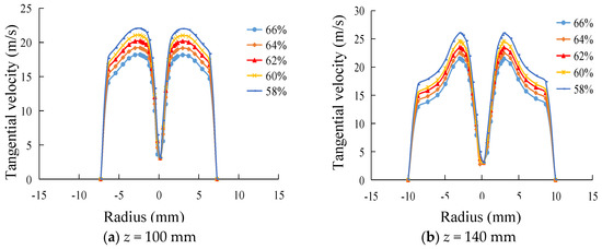
Figure 15.
Effect of concentrations on tangential velocity in the hydrocyclone. (a) z = 100 mm.(b) z = 140 mm.
Figure 16 shows the axial velocity distribution of different cross sections in a hydrocyclone at different concentrations. It can be seen from the figure that the change in feed concentration has little effect on the axial velocity and is basically negligible.
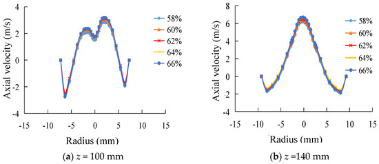
Figure 16.
Effect of concentrations on axial velocity in the hydrocyclone. (a) z = 100 mm.(b) z = 140 mm.
Figure 17 shows the effect of slurry concentration on the separation efficiency. As can be seen from the figure, the separation efficiency gradually decreases as the slurry concentration increases. The reason is that as the concentration of the slurry increases, the viscosity of the drilling fluid also increases. Thus, in the case where the centrifugal strength is constant, the resistance of the particles arranged as per their sizes inside the hydrocyclone increases, causing the coarse particles to be mixed into the overflow and the fine particles to be mixed into the underflow. At the same time, due to the accumulation of a large quantity of solid particles in the underflow outlet area, the resistance of the particles discharged from the underflow outlet is increased, and the particles which should be discharged from the underflow outlet are returned to the separation zone. As a result, the particles are repeatedly separated, resulting in a decrease in the separation efficiency.
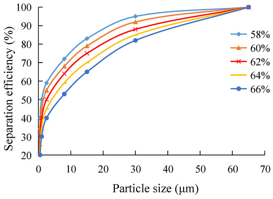
Figure 17.
Effect of slurry concentration on classification efficiency.
3.5. Particle Trajectory
Figure 18 and Figure 19 show the separation process and trajectory of rock debris having a density of 2.6 g/cm3 and barite particles having a density of 4.3 g/cm3 under the effect of a hydrocyclone field. Comparing the two figures, it can be seen from the number of overflow particles that when the particle diameter is the same, the number of particles having a low density (2.6 g/cm3) is significantly larger than the number of particles having a high density (4.3 g/cm3). From the number of underflow particles, the number of high density particles is significantly larger than the number of low density particles. Moreover, as the particle size increases, the classification effect is more pronounced. This indicates that most of the 4.3 g/cm3 particles are discharged through the underflow and most of the 2.6 g/cm3 particles are discharged through the overflow, thereby achieving the effective separation of barite and rock debris.
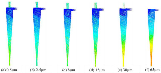
Figure 18.
Trajectory of rock debris particles. (a) 0.5 μm. (b) 2.5 μm. (c) 8 μm. (d) 15 μm. (e) 30 μm. (f) 65 μm.
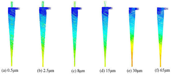
Figure 19.
Trajectory of barite particles. (a) 0.5 μm. (b) 2.5 μm. (c) 8 μm. (d) 15 μm. (e) 30 μm. (f) 65 μm.
It can be observed from Figure 18a,b that the rock debris with a density of 2.6 g/cm3 and diameters of 0.5 μm and 2.5 μm are subjected to weak centrifugal forces after entering through the inlet due to the small particle size. The radius of rotation is also small, so that the particles that enter the inner hydrocyclone of the spiral move upward and are discharged from the overflow outlet. On the other hand, for the material with a density of 4.3 g/cm3, it can be observed from Figure 19a,b that most of the 0.5 μm and 2.5 μm particles are discharged from the overflow outlet, although these high-density particles should have been discharged from the underflow outlet. This shows that the hydrocyclone has a poor effectiveness on the density-based separation of 0.5 μm and 2.5 μm-sized particles, thus forming mismatched products in the overflow and reducing the classification accuracy.
For particles having sizes of 8 μm and 15 μm, it can be found by comparing Figure 18c,d with Figure 19c,d that a small portion of the barite particles break away from the downward spiral motion under the influence of the flow field and instead, move upward. As a result, they enter the upward inner helix and are discharged from the overflow outlet, forming a mismatched product with the low density rock debris particles in the overflow. However, most of the barite particles keep moving in a downward spiral along the wall and exit from the underflow outlet. The results show that for barite particles with particle sizes of 8 μm and 15 μm, despite the generation of mismatched products in the overflow, the quantity of mismatched products is relatively small and the classification effect is good.
For the 30 μm and 65 μm rock debris particles, it can be found by comparing Figure 16e,f with Figure 17e,f that, although the rock debris particles have low densities, due to the large particle size, they are subject to strong centrifugal forces so that they enter the external swirl and are discharged from the underflow outlet. This portion of the low-density rock debris particles should ideally be discharged from the overflow but is wrongly discharged from the underflow, causing them to mix with the barite particles in the underflow to form a mismatched product. For the barite particles of size 30 μm and 65 μm, due to the large density and particle size, the particles can maintain the downward spiral movement under the influence of an inertial force and can quickly enter the underflow outlet without forming mismatched products. As a result, the classification effect is the best in this case.
The separation effect of the cyclone can be observed through the movement trajectory of the particles. Particles with large density but small particle size are easier to enter the inner cyclone and discharge from the overflow. However, particles with small density and large particle size are easier to enter the outer swirl and discharge from the bottom flow.
4. Conclusions
- Through a numerical simulation study on the separation performance of high concentration fine particles, the results show that DDPM can simulate a high-concentration particle field in hydrocyclones.
- The internal pressure drop of the hydrocyclone increases with the increase in feed concentration, while separation efficiency decreases with the increase in material concentration. The results show that feed concentration has a great influence on the separation performance of the cyclone. The higher the feed concentration, the greater the slurry viscosity, which reduces the separation efficiency of the hydrocyclone.
- Particles with large density and small particle size are more likely to enter the internal cyclone and be discharged from the overflow. Particles with small density and large particle size are more likely to enter the external cyclone and be discharged from the underflow. Through the trajectory of the particles, the classification effect of the hydrocyclone and the presence of mismatched products can be visually observed, which provides a theoretical basis for the optimal design of the hydrocyclone structure.
Author Contributions
Conceptualization, Y.Z.; Methodology, Y.Z. and J.X.; Software, Y.Z. and M.Y.; Validation, L.J. and H.W.; Formal Analysis, J.X. and M.Y.; Investigation, Y.Z. and J.Y.; Resources, J.X. and J.Y.; Writing—Original Draft Preparation, Y.Z.; Writing—Review & Editing, M.Y., H.W. and L.J. All authors have read and agreed to the published version of the manuscript.
Funding
This research was funded by the Natural Science Foundation of Shandong Province, China (ZR2020ME105).
Conflicts of Interest
The authors declare no conflict of interest.
References
- Ni, L.; Tian, J.; Zhao, J. Experimental study of the relationship between separation performance and lengths of vortex finder of a novel de-foulant hydrocyclone with continuous underflow and reflux function. Sep. Sci. Technol. 2017, 52, 142–154. [Google Scholar] [CrossRef]
- Ni, L.; Tian, J.; Zhao, J. Experimental study of the effect of underflow pipe diameter on separation performance of a novel de-foulant hydrocyclone with continuous underflow and reflux function. Sep. Purif. Technol. 2016, 171, 270–279. [Google Scholar] [CrossRef]
- Tian, J.; Ni, L.; Song, T.; Olson, J.; Zhao, J. An overview of operating parameters and conditions in hydrocyclones for enhanced separations. Sep. Purif. Technol. 2018, 206, 268–285. [Google Scholar] [CrossRef]
- Vieira, L.G.M.; Silva, D.O.; Barrozo, M.A.S. Effect of Inlet Diameter on the Performance of a Filtering Hydrocyclone Separator. Chem. Eng. Technol. 2016, 39, 1406–1412. [Google Scholar] [CrossRef]
- Vakamalla, T.R.; Mangadoddy, N. Numerical simulation of industrial hydrocyclones performance: Role of turbulence modelling. Sep. Purif. Technol. 2017, 176, 23–39. [Google Scholar] [CrossRef]
- Narasimha, M.; Brennan, M.; Holtham, P.N. A Review of CFD Modelling for Performance Predictions of Hydrocyclone. Eng. Appl. Comput. Fluid Mech. 2007, 1, 109–125. [Google Scholar] [CrossRef]
- Im, I.-T.; Gwak, G.D.; Kim, S.M.; Park, Y.K. A Numerical Study of the Flow Characteristics and Separation Efficiency of a Hydrocyclone. KSCE J. Civ. Eng. 2018, 22, 4272–4281. [Google Scholar] [CrossRef]
- Chu, K.; Wang, B.; Yu, A.; Vince, A. CFD-DEM modelling of multiphase flow in dense medium cyclones. Powder Technol. 2009, 193, 235–247. [Google Scholar] [CrossRef]
- Ghodrat, M.; Qi, Z.; Kuang, S.; Ji, L.; Yu, A. Computational investigation of the effect of particle density on the multiphase flows and performance of hydrocyclone. Miner. Eng. 2016, 90, 55–69. [Google Scholar] [CrossRef]
- Chu, K.; Chen, J.; Yu, A. Applicability of a coarse-grained CFD–DEM model on dense medium cyclone. Miner. Eng. 2016, 90, 43–54. [Google Scholar] [CrossRef]
- Brennan, M.S.; Narasimha, M.; Holtham, P.N. Multiphase modelling of hydrocyclones–prediction of cut-size. Miner. Eng 2007, 20, 395–406. [Google Scholar] [CrossRef]
- Tian, J.Y.; Ni, L.; Song, T.; Shen, C.; Yao, Y.; Zhao, J.N. Numerical study of foulant-water separation using hydrocyclones enhanced by reflux device: Effect of underflow pipe diameter. Sep. Purif. Technol. 2019, 215, 10–24. [Google Scholar] [CrossRef]
- Kyriakidis, Y.N.; Silva, D.O.; Barrozo, M.A.S.; Vieira, L.G.M. Effect of variables related to the separation performance of a hydrocyclone with unprecedented geometric relationships. Powder Technol. 2018, 338, 645–653. [Google Scholar] [CrossRef]
- Mokni, I.; Dhaouadi, H.; Bournot, P.; Mhiri, H. Numerical investigation of the effect of the cylindrical height on separation performances of uniflow hydrocyclone. Chem. Eng. Sci. 2015, 122, 500–513. [Google Scholar] [CrossRef]
- Ni, L.; Tian, J.; Song, T.; Jong, Y.; Zhao, J. Optimizing Geometric Parameters in Hydrocyclones for Enhanced Separations: A Review and Perspective. Sep. Purif. Rev. 2018, 48, 30–51. [Google Scholar] [CrossRef]
- Narasimha, M.; Brennan, M.; Holtham, P. Large eddy simulation of hydrocyclone—prediction of air-core diameter and shape. Int. J. Miner. Process. 2006, 80, 1–14. [Google Scholar] [CrossRef]
- Rakesh, A.; Reddy, V.T.S.R.K.; Mangadoddy, N. Air-Core Size Measurement of Operating Hydrocyclone by Electrical Resistance Tomography. Chem. Eng. Technol. 2014, 37, 795–805. [Google Scholar] [CrossRef]
- Xu, Y.; Song, X.; Sun, Z.; Tang, B.; Yu, J. Steady-state distribution of air-core in a hydrocyclone. Can. J. Chem. Eng. 2017, 95, 757–766. [Google Scholar] [CrossRef]
- Zhang, Y.; Cai, P.; Jiang, F.; Dong, K.; Jiang, Y.; Wang, B. Understanding the separation of particles in a hydrocyclone by force analysis. Powder Technol. 2017, 322, 471–489. [Google Scholar] [CrossRef]
- Vakamalla, T.R.; Koruprolu, V.B.R.; Arugonda, R.; Mangadoddy, N. Development of novel hydrocyclone designs for improved fines classification using multiphase CFD model. Sep. Purif. Technol. 2017, 175, 481–497. [Google Scholar] [CrossRef]
- Cui, B.; Zhang, C.; Wei, D.; Lu, S.; Feng, Y. Effects of feed size distribution on separation performance of hydrocyclones with different vortex finder diameters. Powder Technol. 2017, 322, 114–123. [Google Scholar] [CrossRef]
- Hirt, C.; Nichols, B. Volume of fluid (VOF) method for the dynamics of free boundaries. J. Comput. Phys. 1981, 39, 201–225. [Google Scholar] [CrossRef]
- Chen, W.; Ren, Y.; Zhang, L.; Scheller, P.R. Numerical Simulation of Steel and Argon Gas Two-Phase Flow in Continuous Casting Using LES + VOF + DPM Model. JOM 2018, 71, 1158–1168. [Google Scholar] [CrossRef]
- Fatahian, H.; Fatahian, E.; Nimvari, M.E. Improving efficiency of conventional and square cyclones using different configurations of the laminarizer. Powder Technol. 2018, 339, 232–243. [Google Scholar] [CrossRef]
- Wang, C.; Ji, C.; Zou, J. Simulation and experiment on transitional behaviours of multiphase flow in a hydrocyclone. Can. J. Chem. Eng. 2015, 93, 1802–1811. [Google Scholar] [CrossRef]
- Delgadillo, J.A.; Rosales-Marin, G.; Pérez-Alonso, C.-A.; Ojeda, C. CFD analysis to study the effect of design variables on the particle cut size in hydrocyclones. Asia-Pac. J. Chem. Eng. 2012, 8, 627–635. [Google Scholar] [CrossRef]
- Ji, L.; Kuang, S.; Yu, A. Numerical Investigation of Hydrocyclone Feed Inlet Configurations for Mitigating Particle Misplacement. Ind. Eng. Chem. Res. 2019, 58, 16823–16833. [Google Scholar] [CrossRef]
- Zhang, C.; Wei, D.; Cui, B.; Li, T.; Luo, N. Effects of curvature radius on separation behaviors of the hydrocyclone with a tangent-circle inlet. Powder Technol. 2017, 305, 156–165. [Google Scholar] [CrossRef]
- Chu, K.; Wang, B.; Yu, A.; Vince, A.; Barnett, G.; Barnett, P. CFD–DEM study of the effect of particle density distribution on the multiphase flow and performance of dense medium cyclone. Miner. Eng. 2009, 22, 893–909. [Google Scholar] [CrossRef]
- Zhou, Q.; Wang, C.; Wang, H.; Wang, J. Eulerian–Lagrangian study of dense liquid–solid flow in an industrial-scale cylindrical hydrocyclone. Int. J. Miner. Process. 2016, 151, 40–50. [Google Scholar] [CrossRef]
- Murthy, Y.R.; Bhaskar, K.U. Parametric CFD studies on hydrocyclone. Powder Technol. 2012, 230, 36–47. [Google Scholar] [CrossRef]


Publisher’s Note: MDPI stays neutral with regard to jurisdictional claims in published maps and institutional affiliations. |
© 2021 by the authors. Licensee MDPI, Basel, Switzerland. This article is an open access article distributed under the terms and conditions of the Creative Commons Attribution (CC BY) license (http://creativecommons.org/licenses/by/4.0/).