Article

Alteration of Bentonite Reacted with Cementitious Materials for 5 and 10 years in the Mont Terri Rock Laboratory (CI Experiment)

1
Nuclear Fuel Cycle Backend Research Center, Central Research Institute of Electric Power Industry, 1646 Abiko, Chiba 270-1194, Japan
2
RWI, Institute of Geological Sciences, University of Bern, Baltzerstrasse 3, CH-3012 Bern, Switzerland
*
Author to whom correspondence should be addressed.
Minerals 2021, 11(3), 251; https://doi.org/10.3390/min11030251
Submission received: 4 January 2021 / Revised: 22 February 2021 / Accepted: 22 February 2021 / Published: 28 February 2021

Abstract

:
The cement–clay interaction (CI) experiment was carried out at the Mont Terri rock laboratory to complement the current knowledge on the influence that cementitious materials have on Opalinus Clay (OPA) and bentonite (MX). Drill cores including the interface of OPA, concrete (LAC = low-alkali binder, and OPC = ordinary Portland cement), and MX, which interacted for 4.9 and 10 years, were successfully retrieved after drilling, and detailed analyses were performed to evaluate potential mineralogical changes. The saturated compacted bentonites in core samples were divided into ten slices, profiling bentonite in the direction towards the interface, to evaluate the extent and spatial variation of the mineralogical alteration of bentonite. Regarding the mineral compositions of bentonite, cristobalite was dissolved within a range of 10 mm from the interface in both LAC-MX and OPC-MX, while calcite precipitated near the interface for OPC-MX. In LAC-MX and OPC-MX, secondary products containing Mg (e.g., M-S-H) also precipitated within 20 mm of the interface. These alterations of bentonite developed during the first 4.9 years, with very limited progress observed for the subsequent 5 years. Detectable changes in the mineralogical nature of montmorillonite (i.e., the formation of illite or beidellite, increase in layer charge) did not occur during the 10 years of interaction.

1. Introduction

Bentonite is used in radioactive waste disposal facilities as an engineered barrier owing to its suitable physicochemical properties, such as swelling properties [1], low hydraulic permeability under saturation conditions [1] and cation exchange capacity for radionuclide sorption [2]. Cementitious materials that are used as part of the engineered barrier degrade and generate alkaline pore water, which interacts with natural clays or bentonite. Although bentonite should inhibit the migration of radionuclides, its physicochemical properties change with mineralogical alterations when under alkaline conditions for a long period of time. Therefore, the evaluation of the alteration behavior of bentonite during its interaction with cementitious materials is important for performance assessments and safety analysis for radioactive waste disposal.
The mineralogical alteration of bentonite under alkaline conditions has been reviewed in previous studies [3,4,5]. Based on these reviews, the mineralogical alteration of bentonite has been attributed to the dissolution of the minerals present in bentonite and the subsequent precipitation of secondary phases. The dissolution of the major minerals of bentonite has been extensively investigated; previous studies have summarized the dissolution rates of these minerals [6,7], as well as the potential secondary phases in various chemical conditions [3,5]. Savage et al. (2007) suggested that calcite, dolomite, chalcedony, C(A)SH at variable Ca/Si ratios, K-feldspar, illite, phillipsite, analcime, clinoptilolite, and heulandite are the most likely secondary phases to form in a low-temperature cement–bentonite systems [5].
In addition to the above mineralogical alterations (i.e., dissolution and precipitation), the mineralogical nature of montmorillonite, which is the main component of bentonite, changes as it reacts with alkaline solutions. The illitization of montmorillonite is one of the major alteration phenomena that occur when montmorillonite reacts with a KOH solution [8,9,10,11,12,13]. Beidellitization and a change in the layer charge of montmorillonite also occur when reacting with alkaline solutions [8,9]. These mineralogical alterations of montmorillonite affect its swelling properties. Consequently, there are changes to be expected in the physicochemical properties of bentonite. Therefore, the progress of these changes in the mineralogical nature of montmorillonite with time, is also important for understanding the alteration behavior of bentonite under alkaline conditions.
In radioactive waste disposal facilities, a highly compacted form of bentonite is used to obtain low hydraulic permeability. Many studies on the mineralogical alteration of bentonite, as described above, have been carried out based on a high liquid–solid ratio used in powder samples. In contrast, there are a number of uncertainties that must be considered as the mineralogical alteration of compacted bentonite materials under alkaline conditions has not been extensively investigated [14,15,16,17,18,19]. Long-term alteration of bentonite materials in radioactive waste disposal is predicted by numerical analysis, such as in reactive transport modelling. Validation of the numerical results requires experimental results that take into account specific material properties, such as compacted bentonite and the type of cementitious materials. Such experimental results will also be useful for examining unknown parameters in the numerical analysis, such as reactive surface area of minerals that undergo dissolution. Furthermore, because the performance assessments and safety analysis of radioactive waste disposal targets long-term processes, it is valuable that the results of these experiments, such as those produced by Alonso et al. (2017) [20] and Fernández et al. (2017) [21], are produced under the assumed environmental conditions (e.g., temperature) for as long as possible.
The cement–clay interaction (CI) experiment is carried out at the Mont Terri rock laboratory [22]. The aim of the CI experiment is to reduce uncertainty in process-related cement–clay interactions, such as mineralogical alteration, generation of hyperalkaline pore water chemistry, and changes in the porosity of each material over relatively long-term periods. In the CI experiment, the compacted bentonite and cementitious materials were emplaced in Opalinus Clay (OPA), which is a claystone formation of mid-Jurassic age, investigated at the Mont Terri rock laboratory, and the host rock was foreseen for a deep geological repository envisaged in Switzerland [23]. The field experiment was repeatedly sampled, including the interfaces of each material: OPA, bentonite, and cementitious materials. Interface regions were analyzed to evaluate the mineralogical alteration as a function of space and time [22]. In this study, we characterized bentonite that reacted with cementitious materials for 4.9 and 10 years to specifically estimate the extent of the mineralogical alteration of bentonite.

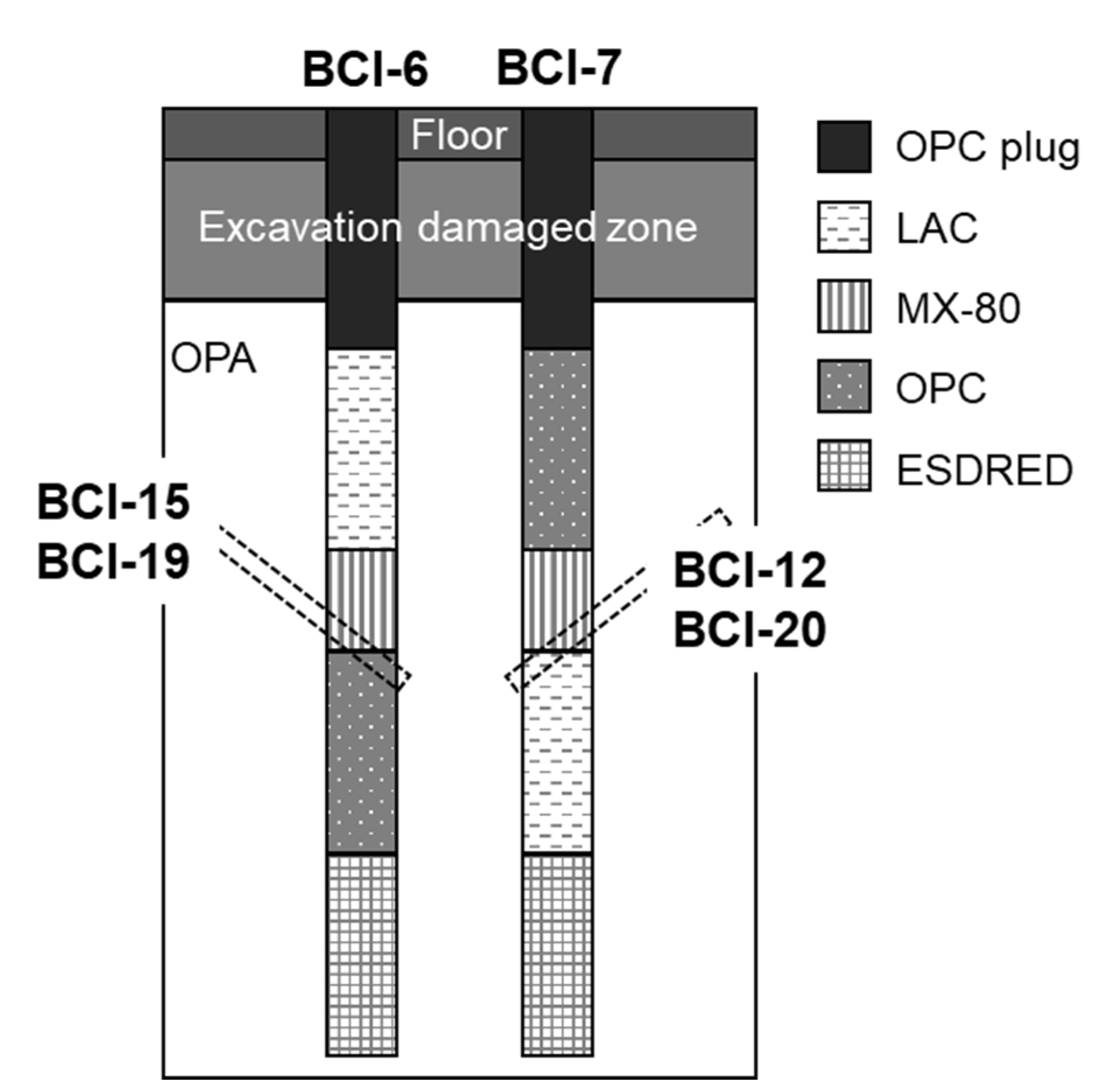
2. Overview of CI Experiment

Previous studies have described the detailed setup of the CI experiment [22,24]. The concrete and bentonite were installed in two vertical boreholes (386 mm in diameter, up to 9 m in length) in the OPA. Three different cements, i.e., ordinary Portland cement (OPC), ESDRED cement, and low alkali cement (LAC), were used to prepare the concrete with common aggregate content and grain size distributions (sand and gravel up to 16 mm). These concretes were set in each part, as shown in Figure 1. Previous studies have also summarized the details of the materials [22,24]. In particular, the pH of OPC and LAC pore water, which influences the chemical interactions between concretes and bentonite, was reported to be equal at 13–13.3 and 12.2–12.4, respectively [22]. MX-80 bentonite (MX), also called Wyoming bentonite, was emplaced as a mixture of highly compacted pellets and fines, covered with a prefabricated concrete lid with a water saturation system and sealed against the overlying concrete section. In other words, MX was installed by sandwiching the top and bottom surfaces with different types of concrete (Figure 1). MX was saturated by artificial pore water (APW) using a water saturation system. APW mainly contained Na, Ca, Mg, Cl, SO4, K, and TIC (Table 1) and provides an approximate of the pore water composition of the OPA at the experimental location in the Mont Terri rock laboratory. The bentonite sections were fully saturated after approximately 1 year (monitoring water uptake and swelling pressure).
The MX employed in the scope of the CI experiment was the same granular bentonite as used in a large-scale emplacement test in the scope of the ESDRED project [25]. The bentonite consisted of small pellets (8–15 mm) with high density (ca. 2000 kg/m3) and low water content (4 wt%), and variable amounts of fine fractions. The CI experiment performed a full-scale emplacement test for bentonite (92 kg), with a relatively low fine fraction (about 20%) which was partially removed by sieving, with an average moisture content of 6.1 wt%. It achieved a bulk density (moist) of 1548 kg/m3 and developed a swelling pressure of >3.3 MPa. A similar mixture was emplaced in the field test, but the emplacement density is not exactly known, approximately 1450 kg/m3. Swelling pressure was monitored at the top of the bentonite sections, and reached 0.6–1.3 MPa after 4 months of saturation, 1.3–1.6 MPa (BCI-6) and 1.4–1.9 MPa (BCI-7) after 12 months. Pressures of 2.2–2.5 MPa (BCI-6) and 2.6 MPa (BCI-7) were reached after 4 years, and remained at similar values 10 years after emplacement.

3. Samples and Methods
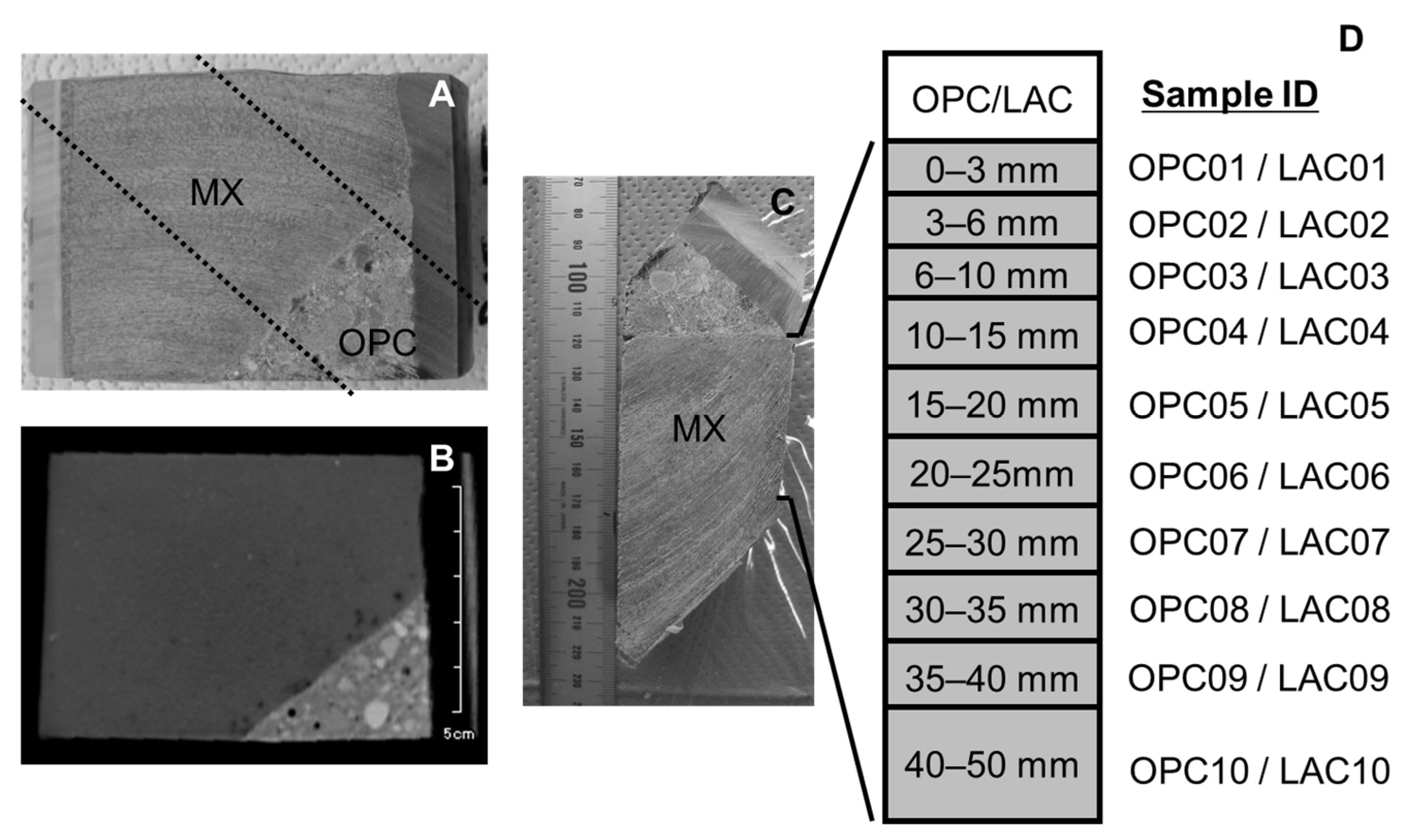
3.1. Samples

A drilling campaign to collect the core samples, including the interface of bentonite and concrete, was carried out 4.9 and 10 years after the installation of each material. Core samples were taken from the bottom interface of the bentonite to avoid any complications from the water saturation system equipped at the top of the bentonite. (Figure 1). The core samples used in this study were BCI-12, BCI-15, BCI-19, and BCI-20. BCI-12 and BCI-20 included the interface of MX and LAC which reacted for 4.9 and 10 years, respectively. BCI-15 and BCI-19 included the interface of MX and OPC which reacted for 4.9 and 10 years, respectively. Figure 2 shows photos and X-ray CT images of BCI-15 and a schematic diagram of sample separation. To evaluate the mineralogical alteration in bentonite, it was divided into ten sections in the range of 50 mm from the interface. The sample ID was numbered sequentially from the interface.

3.2. Sample Characterization

For mineral identification, the X-ray powder diffraction (XRD) patterns of the bentonite were obtained using a randomly oriented sample by XRD with CuKα radiation (RIGAKU RINT 2500, Tokyo, Japan). Samples divided as shown in Figure 2 were dried under vacuum conditions and manually ground using an agate mortar. The obtained powders were loosely compacted in an aluminum folder for XRD measurements to avoid particle orientation. Each sample was scanned at 40 kV, 30 mA, 0.01° 2θ steps and a scan range of 2.5–65° 2θ. The morphologies and major elemental distribution of the bentonite samples were investigated by scanning electron microscopy (FE-SEM: JEOL JSM-7001F, Tokyo, Japan) and electron probe microanalyzer (EPMA: SHIMADZU EPMA1610, Kyoto, Japan; JEOL JXA-8100, Tokyo, Japan), respectively. For FE-SEM imaging, the vacuum-dried bentonite granules were split, and the fracture surface was coated with osmium and observed. EPMA samples, containing the interface of concrete and bentonite, were prepared by encapsulating vacuum-dried samples in resin and polishing the analysis surface.
The extracted cations of bentonite were evaluated as follows. The dry sample (300–500 mg) was dispersed in 10 mL of 1 M NH4Cl solution for 1 day and was solid–liquid separated by centrifugation. This process was repeated five times. All collected solutions were used to measure the concentrations of Na, K, Ca, and Mg by inductively coupled plasma-atomic emission spectrometry (ICP-AES: SHIMADZU ICPS-7510, Kyoto, Japan). This method may indicate a Ca concentration that is overly high compared with the exchangeable Ca content because of the possible dissolution of Ca carbonate contained in the sample, as discussed in a previous study [26]. Therefore, the term “extracted cation” was used in the present study.
The montmorillonite content of bentonite was estimated using the methylene blue absorption test. The methylene blue absorbed on bentonite was measured based on the Japanese Industrial Standard (JIS Z 2451) [27]. The montmorillonite content was calculated by dividing the amount of methylene blue absorbed on bentonite by that of pure montmorillonite, which was assumed to be 140 mmol/100 g [28]. According to JIS Z 2451, the standard deviation of the adsorbed amount is 4–6 mmol/100 g [27]. Therefore, the error in calculated montmorillonite content was ±3–4%.
The mineralogical alteration of montmorillonite in bentonite under alkaline conditions was examined by detecting illitization, beidellitization, and an increase in the layer charge [8,9,10,11,12,13]. To evaluate these alterations, the clay particle fraction of bentonite (0.2–2 μm) was collected by centrifugation. For oriented clay sample preparation, dispersions of the collected clay samples in deionized water were spread onto glass slides and air-dried. To evaluate illitization, the oriented clay sample, after saturation with ethylene glycol (EG), was analyzed by XRD. The percentage of expandable layers (smectite) of the sample was determined using the Δ2θ1–Δ2θ2 diagram [29]. To evaluate beidellitization, a Greene–Kelly (GK) test was carried out for all clay samples. Each sample (30–50 mg) was immersed three times in 10 mL of 1 M LiCl solution for 1 day. The samples were subsequently washed five times with 80% alcohol until the samples were chloride free (AgNO3 test). The Li-saturated samples were spread with water onto silica slide glass. The Li-saturated samples were air-dried and then heated at 300 °C for 24 h in a muffle furnace. Afterwards, the samples were saturated with glycerol (GLY) vapor at 110 °C for 1 day before XRD measurements. The mean layer charge of the clay samples was analyzed using dodecylammonium chloride and octadecylammonium chloride according to the alkylammonium ion exchange method presented in previous studies [30,31,32]. The clay samples (15 mg) were dispersed in 5 mL of 0.1 M dodecylammonium chloride solution and 0.05 M octadecylammonium chloride solution and heated at 65 °C for 2 days. The suspensions were solid–liquid separated by a centrifuge and then treated once again with fresh alkylammonium chloride solution for one day. The samples were then washed with alcohol until the samples were chloride free. The washed clay sample was spread onto glass slides and dried at 65 °C in an oven. The dried samples were analyzed by XRD. The mean layer charge of the clay sample was calculated using the formula proposed by Olis et al. (1990) [31].

4. Results and Discussion

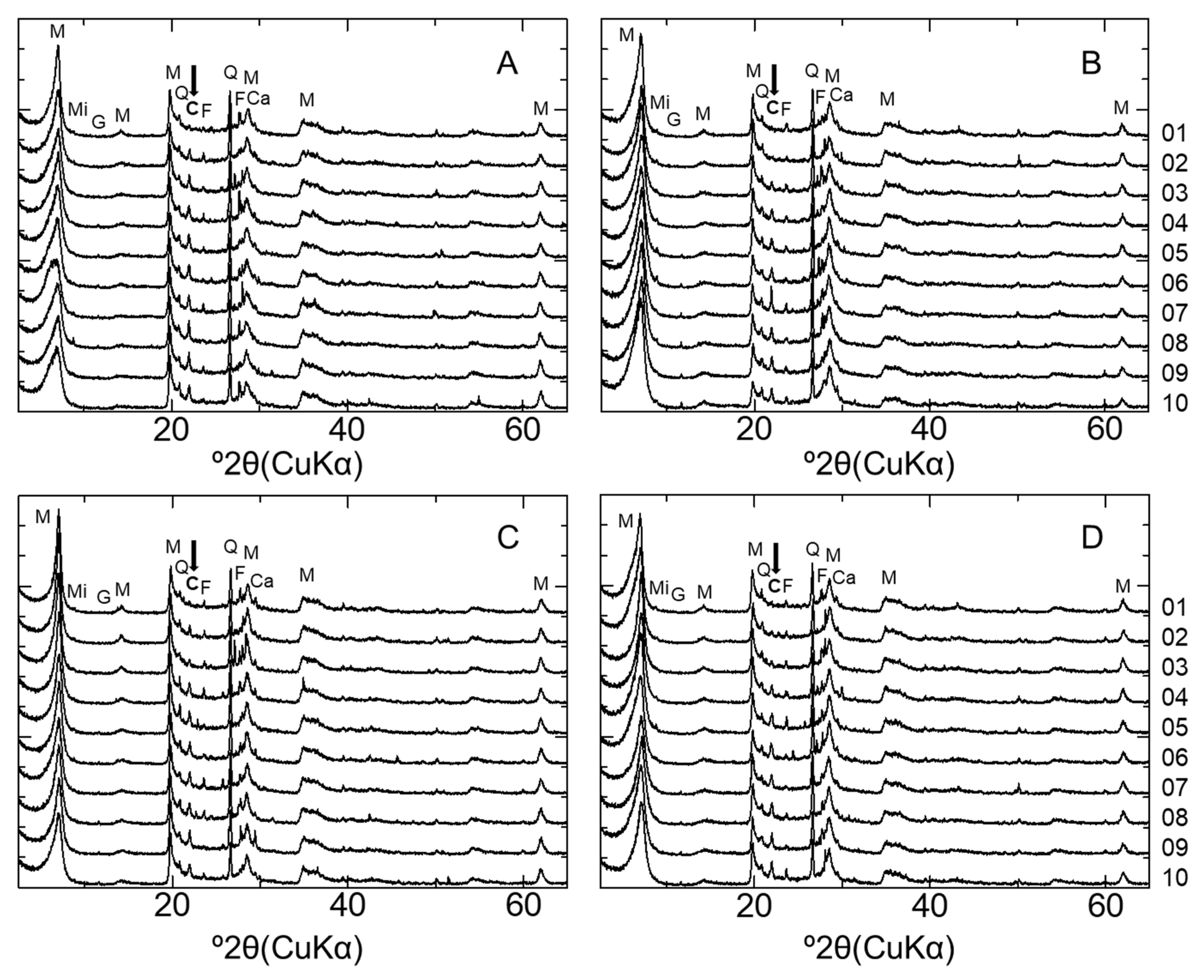
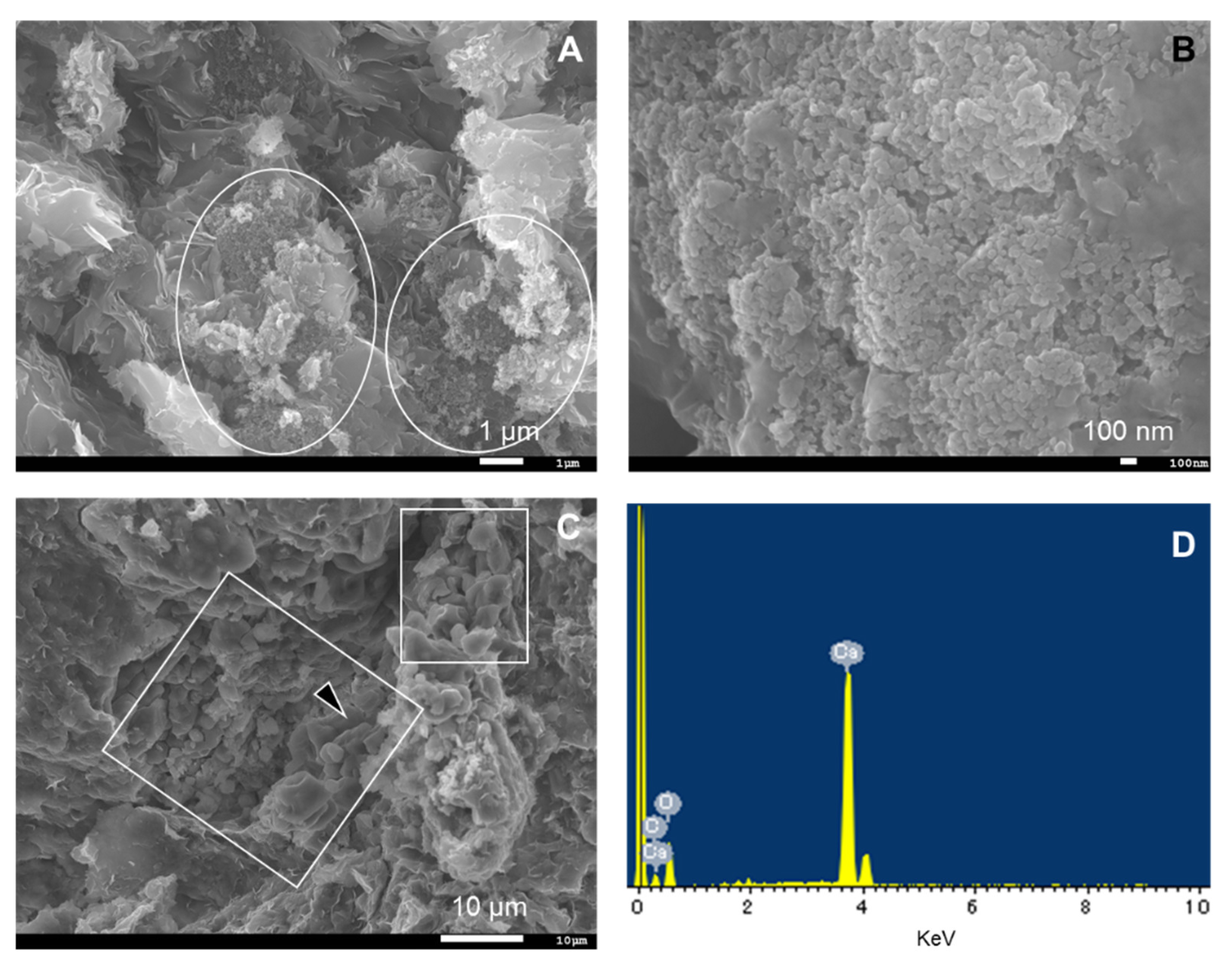
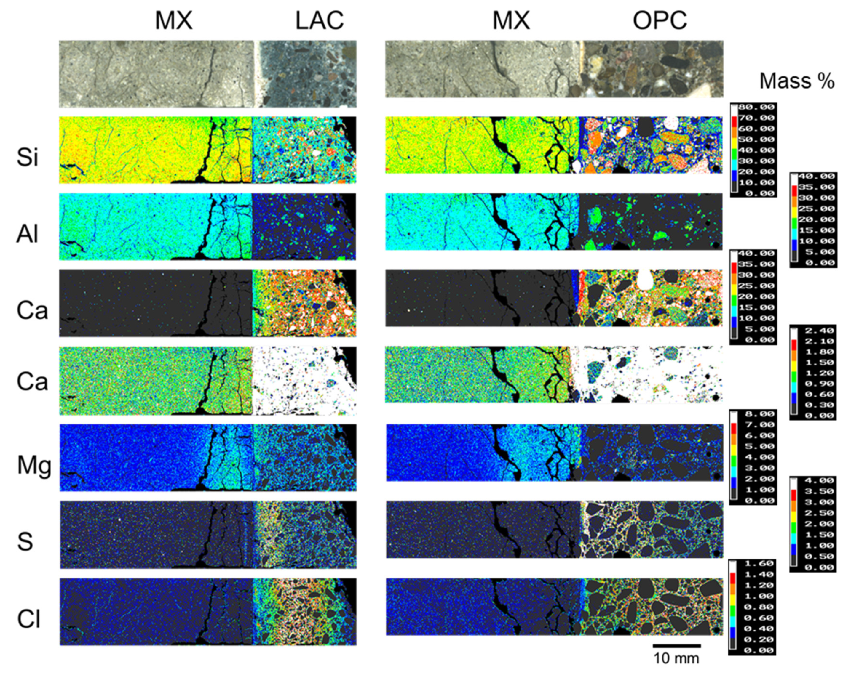
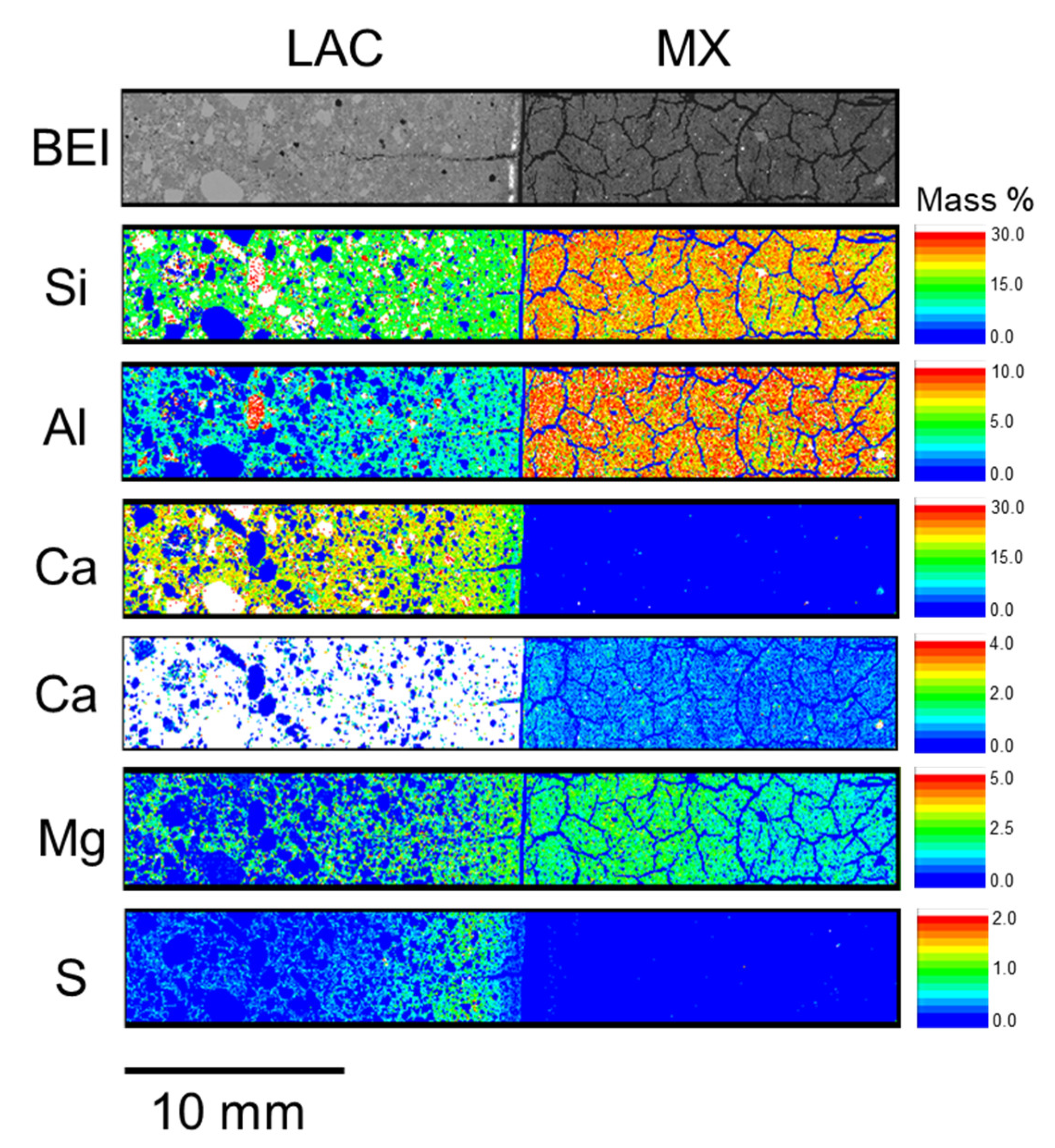
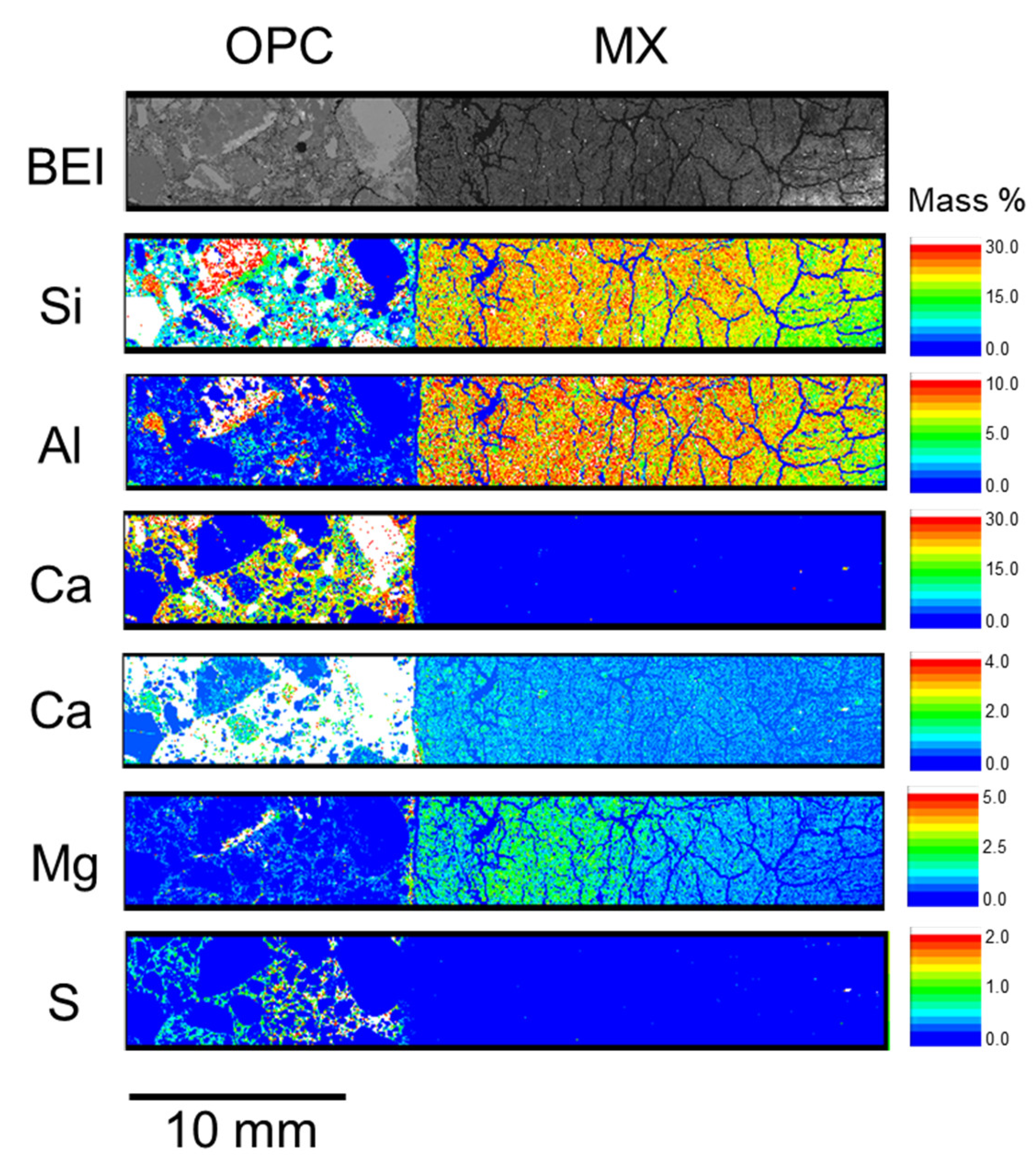
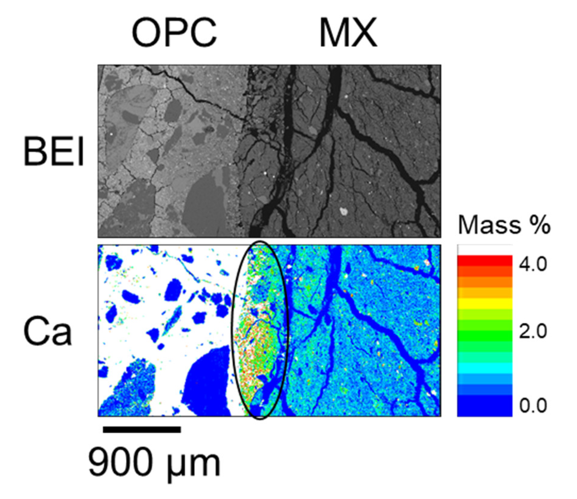
4.1. Mineral Compositions and Element Distributions

Figure 3 shows the XRD patterns of the bentonite samples. Although no XRD analysis of the initial MX used for the CI experiment was conducted, Karnland (2010) summarized the mineral composition of MX-80 for the commercial batches of each year, with the mean composition determined as montmorillonite (81.4%), illite (0.8%), calcite (0.2%), cristobalite (0.9%), gypsum (0.9%), muscovite (3.4%), plagioclase (3.5%), pyrite (0.3%), quartz (3.0%), and tridymite (3.8%) [2]. The MX used in the present study mainly comprised montmorillonite, quartz, cristobalite, and feldspar and contained extremely small amounts of mica minerals, gypsum, and calcite. In the XRD patterns recorded to evaluate mineral composition, each peak attributed to feldspar occurred randomly regardless of the distance from the interface, although sufficient attention was paid to sample homogenization and orientation randomization (see above). Therefore, all samples were concluded to contain feldspar, but the exact variation of feldspar amount could not be assessed. In contrast, the peak intensity of cristobalite was weak near the interface (within 10 mm) for both LAC-MX and OPC-MX (Figure A1). Figure 4A,B show SEM images of cristobalite in BCI-15. These cristobalites were observed at a location more than 60 mm from the interface, but they were hardly observed near the interface. From these results, as cristobalite was characterized as fine particles with a diameter of several hundred nm, cristobalite had a high reactivity and dissolved by reaction with cementitious fluids near the interface. Comparing between the 4.9- and 10-year samples, the range in which cristobalite was dissolved was slightly more advanced in LAC-MX after 10 years but was almost the same in OPC-MX. This indicates that the advance of the dissolution front for cristobalite occurred during the first 4.9 years of interaction, after which there was a strong decrease in its propagation rate. A small peak of gypsum was observed far from the interface, disappearing at a distance of ~20 mm from the interface. As Karnland (2010) reported that gypsum is initially contained in MX-80 [2], this behavior was ascribed to the dissolution of gypsum near the interface.
Figure 5 shows the EPMA-determined elemental distributions of 10-year core samples. For OPC-MX (BCI-19), a high Ca concentration was detected near the interface, as was also observed in the SEM and EPMA analyses of BCI-15 (Figure 4C and Figure A4). Figure 4C shows an SEM image of calcite grains near the interface (~1 mm). In SEM images, calcite was hardly observed far from the interface because of its extremely small content. The results of SEM and EPMA analyses suggest that calcite precipitated only near the interface because of the interaction between MX and OPC.
In Figure 5, a notable elemental re-distribution in the bentonite component is the high Mg concentration near the interface in both LAC-MX and OPC-MX. This high Mg concentration was also observed in the 4.9-year core sample (Figure A2 and Figure A3). This suggests that secondary products containing Mg were precipitated near the interface. Mäder et al. (2017) and Bernard et al. (2020) reported the possible formation of magnesium-silicate-hydrate (M-S-H), or hydrotalcite-like phases, due to the interaction between OPA and cementitious materials in the CI experiment [24,33]. The Mg-containing secondary products observed herein were also presumed to be M-S-H, hydrotalcite-like, or similar phases, as OPA and MX are similar clayey materials. In the concrete section, the distribution of the high concentrations occurred from the interface in the order of S and Cl in both LAC and OPC (Figure 5). In other words, Cl penetrated the concrete section more deeply than S did. The depth of S and Cl penetration into concrete was deeper in OPC than in LAC. The enrichment zones of these elements were distributed parallel to the interface between each concrete and MX. Therefore, these elements were concluded to penetrate concrete through MX. As the APW used to saturate MX and the pore water of OPA [34] contained substantial amounts of S and Cl, these elements penetrated the concrete along with the saturation of MX and precipitated. Although the precipitates were not analyzed, they presumably contained new products such as monosulfate and/or ettringite and Friedel’s salt.

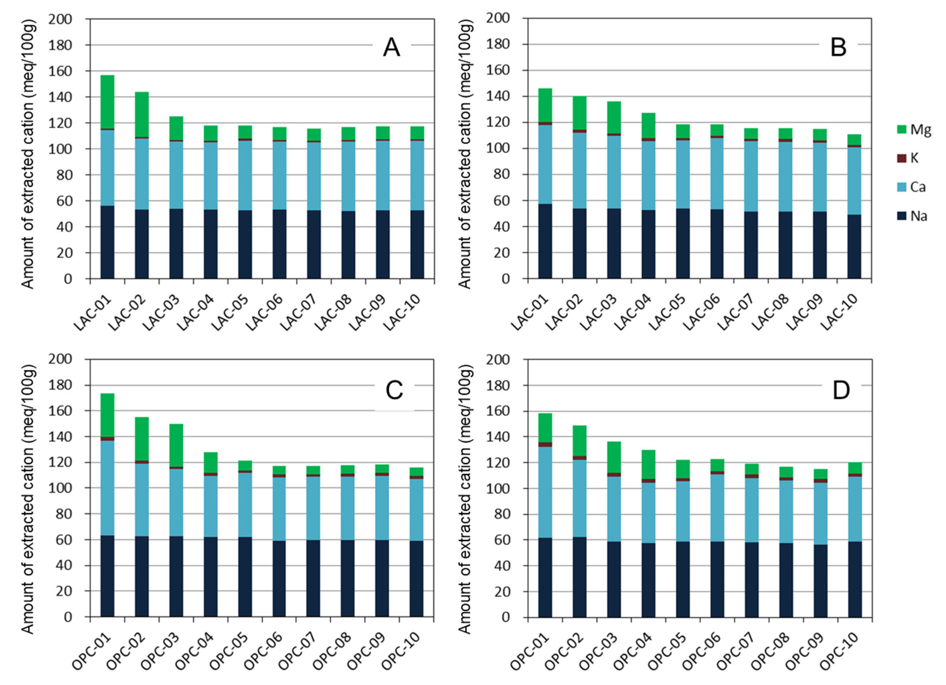
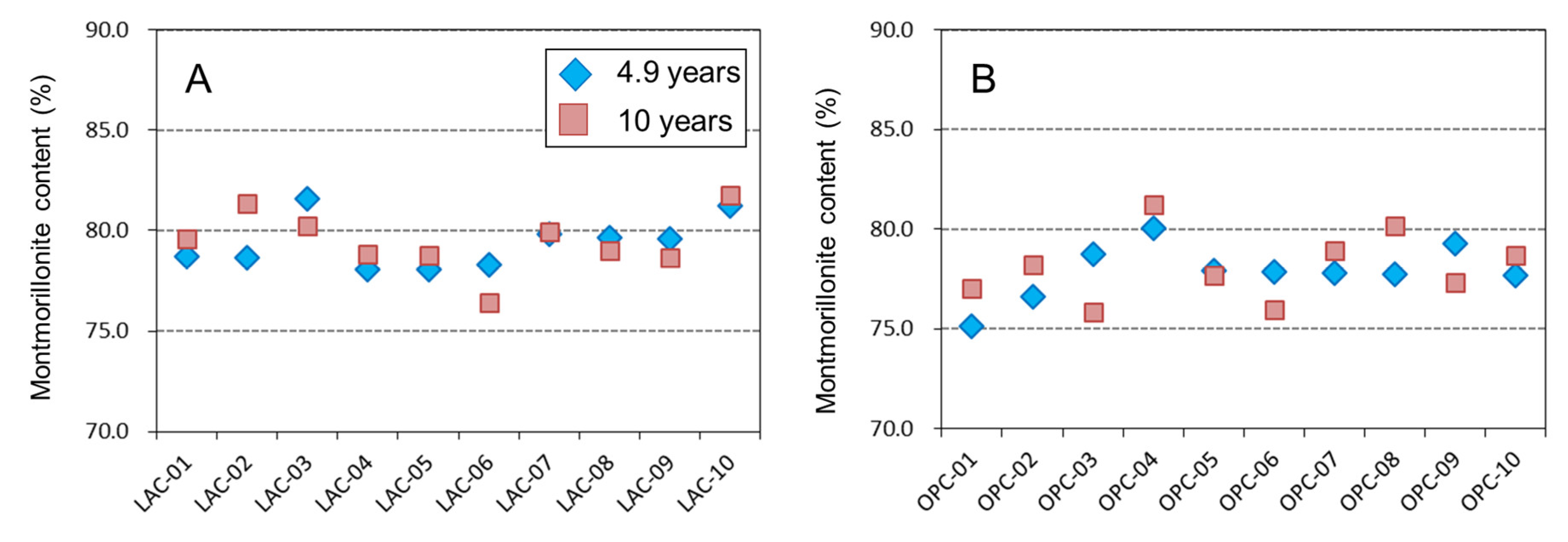
4.2. Extracted Cations and Montmorillonite Contents in Bentonite

Figure 6 shows the compositions of the extracted cations in bentonite. As MX was saturated by APW and the pore water of OPA containing various ions, the extracted cation composition in Figure 6 represents that after the reaction of MX and these solutions. Karnland (2010) summarized the exchangeable cations in MX-80 for batches of each year [2]. From this report, the mean exchangeable Na, Ca, K and Mg contents of MX-80 were obtained as 55, 13, 1 and 5 meq/100 g, respectively. The extracted Na, K, and Mg contents of MX far from the interface were similar to the above values, whereas the extracted Ca content exceeded the exchangeable Ca content reported by Karnland (2010) [2]. This difference was due to the dissolution of the small amounts of calcite contained in MX during extraction by 1 M NH4Cl solution, as described above.
Here, the amounts of extracted Ca and Mg near the interface (0–15 mm) were higher than those far from the interface. The amounts of extracted Na and K were almost constant, independent of the distance from the interface. The ion exchange reaction of bentonite results in an increased content of a certain cation while decreasing the contents of other cations. Therefore, this result suggests that the ion exchange reaction is not the main cause of the increase in Ca and Mg contents near the interface. Furthermore, the total amount of extracted cations increases near the interface. If the extracted cation is electrostatically adsorbed, the negative charge of bentonite, especially montmorillonite, should have increased near the interface. However, no change was observed in the mean layer charge of montmorillonite, as described below. Based on these observations, we suggest that the increase in the amount of extracted Ca and Mg is due to the dissolution of the mentioned secondary phases (i.e., calcite and Mg-binding phases) during the extraction treatment. In the comparison between the 4.9- and 10-year samples, both Ca and Mg in OPC-MX and LAC-MX showed almost the same value and distance from the interface with no change in the increasing total extracted cations. These results indicate that the precipitation of secondary phases occurred mainly during the 4.9-year interaction and had little progress over the next five years.
Figure 7 shows the content of montmorillonite in bentonite. The montmorillonite content of MX was approximately 78~80%. This value is almost identical to the montmorillonite content obtained by Karnland (2010) [2] when the reported variation in each year is considered. In LAC-MX, no change was observed in the 4.9- and 10-year samples, such that we consider that there was no montmorillonite dissolution. In OPC-MX, the montmorillonite content appears to show a slight decrease near the interface, but it was not a significant difference considering the error of the methylene blue adsorption experiment. These results indicate that the dissolution of montmorillonite did not significantly progress in the interaction between LAC-MX and OPC-MX for 10 years.
The dissolution rate of montmorillonite under alkaline conditions depends on the pH, temperature, and degree of undersaturation (ΔGr) [35,36,37]. Furthermore, for compacted bentonite, the reactive surface area for dissolution, i.e., the edge surface area [38], would be reduced as the bentonite is compacted and the component minerals are coated with each other. To evaluate the dissolution rate of montmorillonite in a realistic compacted bentonite–concrete interaction, it is important to analyze core samples that have reacted for an extended period to detect dissolution and obtain data on the above influencing factors.

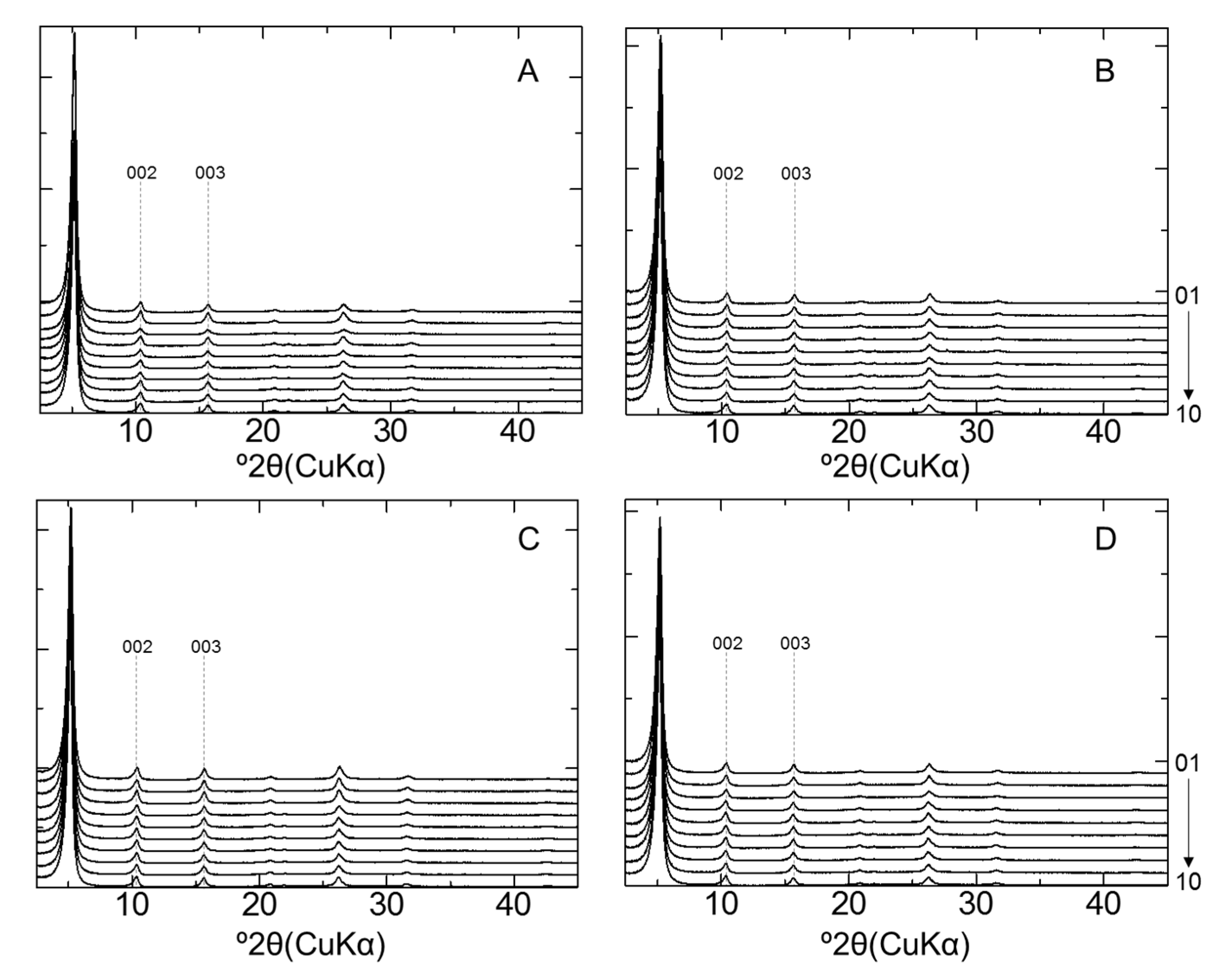
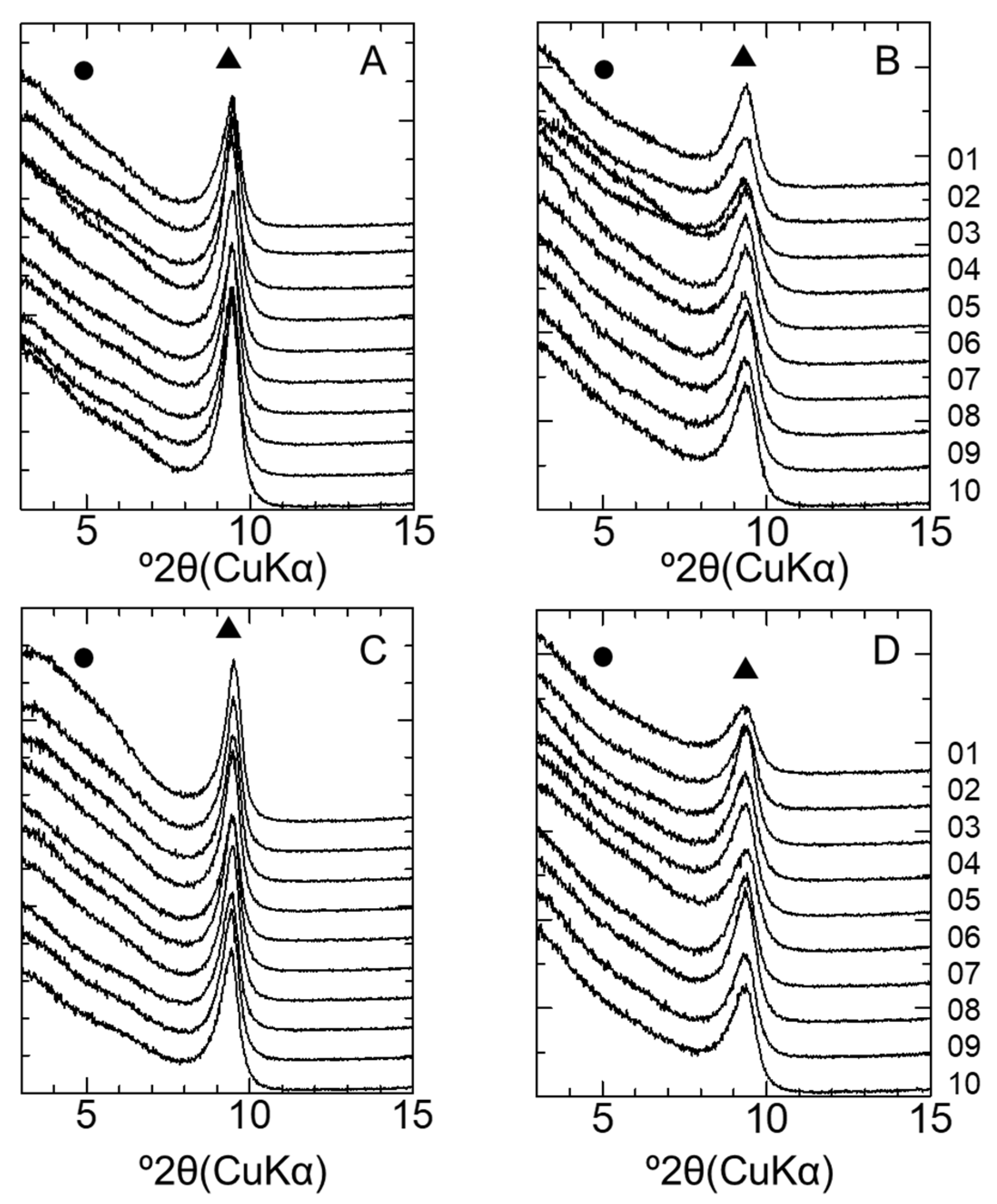
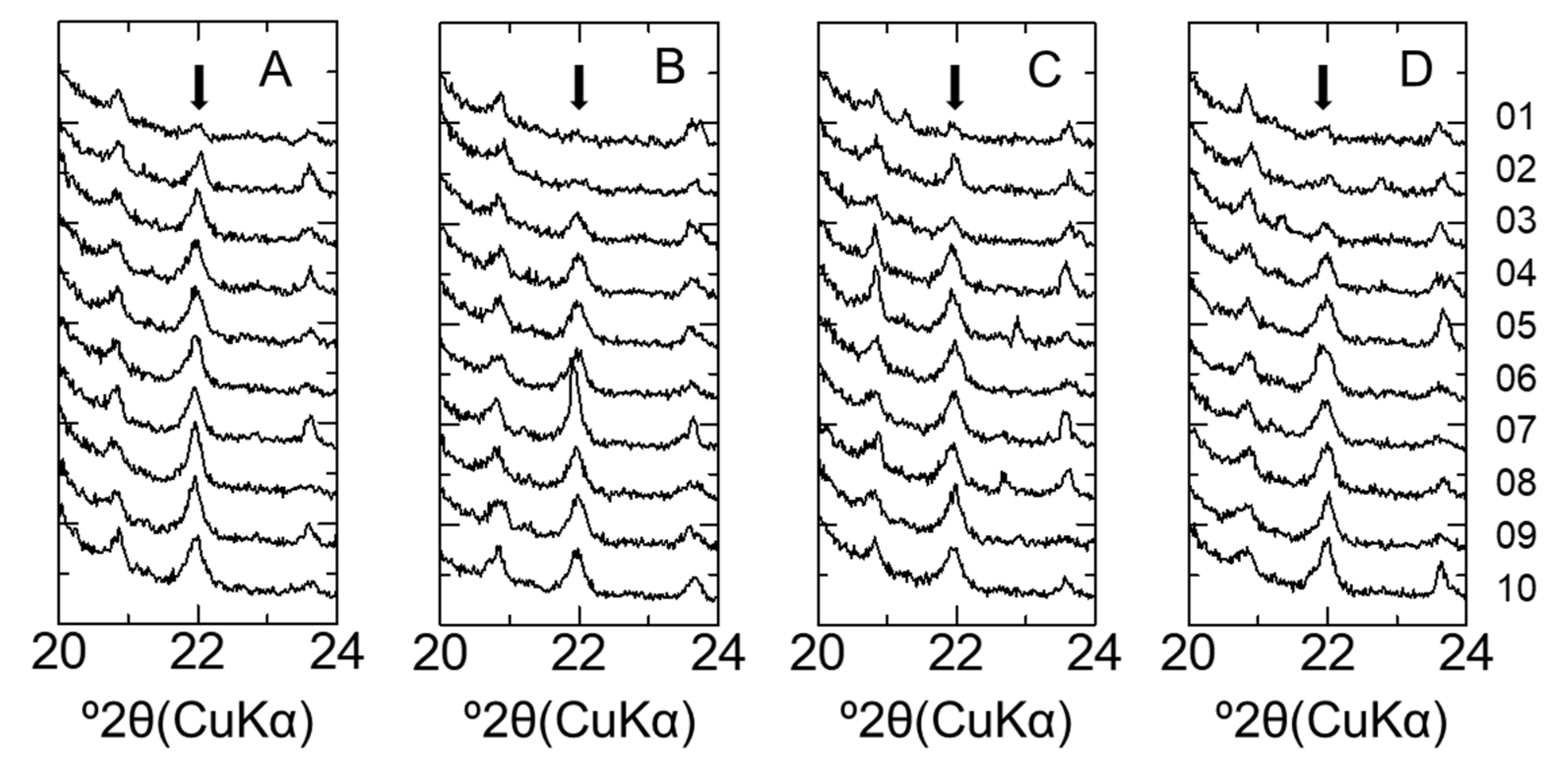
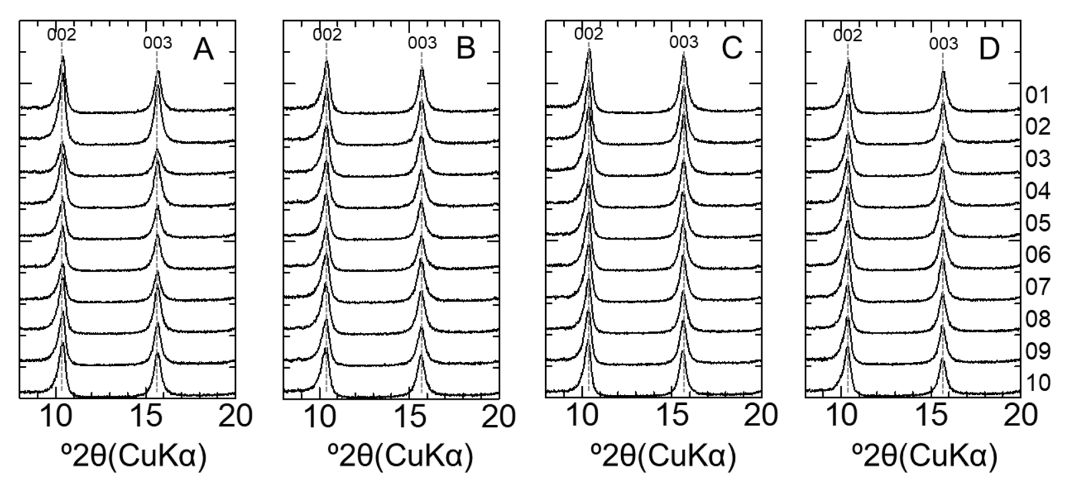
4.3. Mineralogical Characteristics of Montmorillonite

The illite % of the illite/smectite interstratified mineral (I/S) was determined by XRD analysis of the sample treated with EG. If smectite-rich R0 I/S forms from smectite, the peaks of d002 and d003 of the sample shift to low and high angles, respectively [39]. Figure 8 shows the XRD patterns of the clay fraction samples collected from each bentonite sample after EG treatment. No peak shifts in d002 and d003 were observed in any of the samples (Figure A5). The illite% was evaluated using the Δ2θ1–Δ2θ2 diagram [29]; consequently, the formation of an illite layer was not observed. Therefore, illitization of montmorillonite did not occur during the 10-year interaction in both LAC-MX and OPC-MX.
Montmorillonite and beidellite have mainly negative charges (layer charge) on octahedral and tetrahedral sheets, respectively. These clay minerals can be identified by the GK test, featuring characteristic XRD peaks at 0.95 nm (montmorillonite) and 1.77 nm (beidellite) [40]. Figure 9 shows the XRD patterns of the clay fraction samples after the GK test. Although some patterns appear to show a weak broad shoulder around 3~7° 2θ, this remains unexplained at present. On the other hand, all samples showed a peak near 0.95 nm, which indicated that almost no beidellite was formed. The mean layer charge of montmorillonite was evaluated from the XRD patterns of the alkylammonium treated samples (Table 2). From these results, the mean layer charge shows almost the same value, where no change was observed during the 10-year interaction in both LAC-MX and OPC-MX. From the above evaluation, we clarified that illitization and changes in layer charge characteristics (i.e., position and the mean layer charge) of montmorillonite did not occur during the 10-year interaction. The change in the mineralogical nature of montmorillonite, as described above, and the change in the exchangeable cation compositions affect the swelling property of bentonite. As these changes were not observed in this study, there would be no change in the swelling property of MX due to that effect for 10 years.

4.4. Bentonite Alteration during 10 Years of Interaction

In the CI experiment, the main alterations of bentonite due to interaction with cementitious materials were the dissolution of cristobalite and the precipitation of secondary phases containing Ca and Mg. The initial pH of MX-80 slurry and the pore water of compacted samples has been previously reported to be approximately 8~9 [41,42]. The direct measurement of pH in the alteration zone is not possible, but the observed dissolution of cristobalite and precipitation of secondary products mentioned imply a high-pH perturbation extending some distance into the bentonite. Particularly, all secondary Mg-phases showed a strongly reduced solubility with increasing pH, and therefore, zones of Mg precipitation outline a high-pH front. The complexity of such mineral reaction fronts is best clarified by using reactive-transport modeling.
These alterations mainly progressed in the first 4.9 years with little progress during the next five years. Although the cause of the change in expansion rate of alteration zone is not yet clear, the following two possibilities can be considered. The first is the possibility that alteration occurred in a relatively short time after each material was installed in the vertical boreholes. Cementitious materials had excess water and pore water when the hydration reaction was in progress after casting. In contrast, bentonite was not completely saturated with water immediately after installation. Therefore, this would suggest that the highly alkaline solution in the cementitious materials was easily transferred to the bentonite by suction. Due to this rapid migration of highly alkaline solutions, the dissolution of highly reactive minerals (e.g., cristobalite with a fine particle size) and the precipitation of secondary products would proceed in a relatively short period of time. The permeation of the solution into the unsaturated bentonite causes the swelling of montmorillonite near the interface. The swelling of montmorillonite improves the water tightness and consequently inhibits further penetration of the solution. In addition, the supply of APW and the pore water of OPA could also have contributed to a reduction in suction. Therefore, it would suggest that the distance of the observed alteration area, i.e., the range of the initial alkaline solution penetration, was limited to approximately 15 mm or less.
The second possibility is the effect of clogging by secondary products. The precipitation of secondary products, calcite, and Mg-binding phases may reduce the porosity of bentonite, resulting in limited mass transfer. Similar to this manner, the precipitation of S- and Cl-binding phases and the progressing hydration in cementitious materials may also contribute to the reduction in porosity. As a result, this would inhibit the expansion rate of the alteration zones. This second possibility, especially the effect that a decrease in the porosity has on the expansion rate of the alteration zones, will be also discussed in future studies using reactive-transport models. The finding that the observed expansion rate of the alteration zones occurs in a non-linear manner is important for predictions of long-term bentonite–cement interactions. For predictions of long-term interactions, one must not only elucidate the mechanism of the observed alteration behavior (the two possibilities mentioned above), but also obtain data for the slow alteration rates (e.g., dissolution of montmorillonite). This will be revealed in future analyses of long-term interacting core samples from the CI experiment (e.g., 20 years).

5. Conclusions

To understand the alteration behavior of bentonite caused by the interaction with cementitious materials, we analyzed core samples collected from the CI experiment conducted at the Mont Terri rock laboratory. Cristobalite dissolved within the range of 10 mm from the interface and calcite precipitated near the interface. Secondary products containing Mg (e.g., M-S-H or hydrotalcite-like phases) probably also precipitated in the range of 20 mm from the interface. In the extracted cation composition, the amounts of Ca and Mg increased near the interface due to the dissolution of these secondary products during the extraction process. These alterations of bentonite mainly progressed during the first 4.9 years (possibly within a much shorter time), with little progress occurring during the next five years. It must be noted that the mineralogical characteristics of montmorillonite in bentonite did not change during the 10-year interaction; consequently, the swelling property of MX should not have changed due to this effect for 10 years. Although the mechanism of the observed alteration behavior—as mentioned above—is not yet entirely clear, the finding that the observed expansion rate of the alteration zones is highly non-linear is important for predictions of long-term bentonite–cement interactions.
The CI experiment represents a long-term experiment at a relatively large scale, evaluating the interaction of compacted bentonite with concrete, taking into account relevant materials expected in radioactive waste repositories. We believe that the results of the detailed analysis in this paper can be used to advance numerical analyses of long-term interactions by reactive transport modelling.

Author Contributions

Conceptualization, S.Y.; Investigation, S.Y., M.S., D.M., and Y.W.; Project administration, S.Y.; Resources, A.J. and U.M.; Writing—original draft, S.Y. and U.M.; Writing—review & editing, M.S., D.M., Y.W., and A.J. All authors have read and agreed to the published version of the manuscript.

Funding

The CI Project is funded by ANDRA (France), CRIEPI (Japan), IRSN (France), FANC (Belgium), Nagra (Switzerland), NWMO (Canada), Obayashi (Japan), RWM (UK) and SCK-CEN (Belgium). It financed all drilling campaigns, a part of sample preparation, and some earlier analytical costs.

Data Availability Statement

Data is contained within this article.

Acknowledgments

Discussions with Lukas Martin of Nagra are greatly appreciated. The authors like to acknowledge the support by the funding organizations of the CI Project and the Mont Terri Consortium, specifically the scientific and technical team operating the Mont Terri rock laboratory (Swisstopo) for field support.

Conflicts of Interest

The authors declare no conflict of interest.

Appendix A

Figure A1. XRD patterns of bentonite in LAC-MX and OPC-MX. (A) LAC-MX_4.9 y, (B) LAC-MX_10 y, (C) OPC-MX_4.9 y, and (D) OPC-MX_10 y. Arrows indicate the peak position of cristobalite.
Minerals 11 00251 g0a1
Figure A2. Elemental distribution of LAC-MX_4.9 y (BCI-12).
Minerals 11 00251 g0a2
Figure A3. Elemental distribution of OPC-MX_4.9 y (BCI-15).
Minerals 11 00251 g0a3
Figure A4. Calcium distribution of OPC-MX_4.9 y (BCI-15).
Minerals 11 00251 g0a4
Figure A5. XRD patterns of montmorillonite after EG treatment. (A) LAC-MX_4.9 y, (B) LAC-MX_10 y, (C) OPC-MX_4.9 y, and (D) OPC-MX_10 y. This figure shows an enlargement of 8–20° 2θ in Figure 8.
Minerals 11 00251 g0a5

References

  1. Karnland, O.; Olsson, S.; Nilsson, U. Mineralogy and Sealing Properties of Various Bentonites and Smectite-Rich Clay Materials; SKB Technical Report TR-06-30; SKB: Stockholm, Sweden, 2006. [Google Scholar]
  2. Karnland, O. Chemical and Mineralogical Characterization of the Bentonite Buffer for the Acceptance Control Procedure in a KBS-3 Repository; SKB Technical Report TR-10-60; SKB: Stockholm, Sweden, 2010. [Google Scholar]
  3. Oda, C.; Honda, A.; Savage, D. An Analysis of Cement-Bentonite Interaction and Evolution of Pore Water Chemistry; NUMO-TR-04-05; NUMO: Tokyo, Japan, 2004; pp. 74–79. [Google Scholar]
  4. Gaucher, E.C.; Blanc, P. Cement/clay interactions—A review: Experiments, natural analogues, and modeling. Waste Manag. 2006, 26, 778–788. [Google Scholar] [CrossRef] [PubMed] [Green Version]
  5. Savage, D.; Walker, C.; Arthur, R.; Rochelle, C.; Oda, C.; Takase, H. Alteration of bentonite by hyperalkaline fluids: A review of the role of secondary minerals. Phys. Chem. Earth 2007, 32, 287–297. [Google Scholar] [CrossRef]
  6. Bandstra, J.Z.; Buss, H.L.; Campen, R.K.; Liermann, L.J.; Moore, J.; Hausrath, E.M.; Navarre-Sitchler, A.K.; Jang, J.H.; Brantley, S.L. Compilation of mineral dissolution rates. In Kinetics of Water-Rock Interaction; Brantley, S.L., Kubicki, J.D., White, A.F., Eds.; Springer: New York, NY, USA, 2008; pp. 737–823, (Appendix). [Google Scholar]
  7. Cama, J.; Ganor, J. Dissolution kinetics of clay minerals. In Natural and Engineered Clay Barriers; Tournassat, C., Steefel, C.I., Bourg, I.C., Bergaya, F., Eds.; Elsevier: Amsterdam, The Netherlands, 2015; Volume 6, pp. 101–153. [Google Scholar]
  8. Inoue, A. Potassium fixation by clay minerals during hydrothermal treatment. Clays Clay Miner. 1983, 31, 81–91. [Google Scholar] [CrossRef]
  9. Eberl, D.D.; Środoń, J.; Northrop, H.R. Potassium fixation in smectite by wetting and drying. In Geochemical Processes at Mineral Surfaces; Davis, J.A., Hayes, K.F., Eds.; ACS: Washington, DC, USA, 1986; pp. 296–326. [Google Scholar]
  10. Eberl, D.D.; Velde, B.; McCormick, T. Synthesis of illite-smectite from smectite at earth surface temperatures and high pH. Clay Miner. 1993, 28, 49–60. [Google Scholar] [CrossRef]
  11. Bauer, A.; Velde, B. Smectite transformation in high molar KOH solutions. Clay Miner. 1999, 34, 259–273. [Google Scholar] [CrossRef]
  12. Drief, A.; Martinez-Ruiz, F.; Nieto, F.; Sanchez, N.V. Transmission electron microscopy evidence for experimental illitization of smectite in K-enriched seawater solution at 50 °C and basic pH. Clays Clay Miner. 2002, 50, 746–756. [Google Scholar] [CrossRef]
  13. Fernández, R.; Ruiz, A.I.; Cuevas, J. The role of smectite composition on the hyperalkaline alteration of bentonite. Appl. Clay Sci. 2014, 95, 83–94. [Google Scholar] [CrossRef]
  14. Nakayama, S.; Sakamoto, Y.; Yamaguchi, T.; Akai, M.; Tanaka, T.; Sato, T.; Iida, Y. Dissolution of montmorillonite in compacted bentonite by highly alkaline aqueous solutions and diffusivity of hydroxide ions. Appl. Clay Sci. 2004, 27, 53–65. [Google Scholar] [CrossRef]
  15. Yamaguchi, T.; Sakamoto, Y.; Akai, M.; Takazawa, M.; Iida, Y.; Tanaka, T.; Nakayama, S. Experimental and modeling study on long-term alteration of compacted bentonite with alkaline groundwater. Phys. Chem. Earth 2007, 32, 298–310. [Google Scholar] [CrossRef]
  16. Yamaguchi, T.; Sawaguchi, T.; Tsukada, M.; Kadowaki, M.; Tanaka, T. Changes in hydraulic conductivity of sand-bentonite mixtures accompanied by alkaline alteration. Clay Miner. 2013, 48, 403–410. [Google Scholar] [CrossRef]
  17. Fernández, R.; Ruiz, A.I.; Cuevas, J. Formation of C-A-S-H phases from the interaction between concrete or cement and bentonite. Clay Miner. 2016, 51, 223–235. [Google Scholar] [CrossRef] [Green Version]
  18. González-Santamaría, D.E.; Fernández, R.; Ruiz, A.I.; Ortega, A.; Cuevas, J. Bentonite/CEM-II cement mortar INTERFACE EXPERIMENTS: A proxy to in situ deep geological repository engineered barrier system surface reactivity. Appl. Geochem. 2020, 117, 104599. [Google Scholar] [CrossRef]
  19. González-Santamaría, D.E.; Fernández, R.; Ruiz, A.I.; Ortega, A.; Cuevas, J. High-pH/low pH ordinary Portland cement mortars impacts on compacted bentonite surfaces: Application to clay barriers performance. Appl. Clay Sci. 2020, 193, 105672. [Google Scholar] [CrossRef]
  20. Alonso, M.C.; Calvo, J.L.G.; Cuevas, J.; Turrero, M.J.; Fernández, R.; Torres, E.; Ruiz, A.I. Interaction processes at the concrete-bentonite interface after 13 years of FEBEX-Plug operation. Part I: Concrete alteration. Phys. Chem. Earth 2017, 99, 38–48. [Google Scholar] [CrossRef]
  21. Fernández, R.; Torres, E.; Ruiz, A.I.; Cuevas, J.; Alonso, M.C.; Calvo, J.L.G.; Rodríguez, E.; Turrero, M.J. Interaction processes at the concrete-bentonite interface after 13 years of FEBEX-Plug operation. Part II: Bentonite contact. Phys. Chem. Earth 2017, 99, 39–63. [Google Scholar] [CrossRef]
  22. Jenni, A.; Mäder, U.; Lerouge, C.; Gaboreau, S.; Schwyn, B. In situ interaction between different concretes and Opalinus Clay. Phys. Chem. Earth Parts A/B/C 2014, 70, 71–83. [Google Scholar] [CrossRef] [Green Version]
  23. Bossart, P.; Bernier, F.; Birkholzer, J.; Bruggeman, C.; Connolly, P.; Dewonck, S.; Fukaya, M.; Herfort, M.; Jensen, M.; Matray, J.M.; et al. Mont Terri rock laboratory, 20 years of research: Introduction, site characteristics and overview of experiments. Swiss J. Geosci. 2017, 110, 3–22. [Google Scholar] [CrossRef] [Green Version]
  24. Mäder, U.; Jenni, A.; Lerouge, C.; Gaboreau, S.; Miyoshi, S.; Kimura, Y.; Cloet, V.; Fukaya, M.; Claret, F.; Otake, T.; et al. 5-year chemico-physical evolution of concrete-claystone interfaces. Swiss J. Geosci. 2017, 110, 307–327. [Google Scholar] [CrossRef] [Green Version]
  25. Plötze, M.; Weber, H.P. ESDRED: Emplacement tests with granular bentonite MX-80: Laboratory results from ETH Zürich. Nagra Arbeitsbericht 2007, 7, 1–10. [Google Scholar]
  26. Dohrmann, R. Cation exchange capacity methodology I: An efficient model for the detection of incorrect cation exchange capacity and exchangeable cation results. Appl. Clay Sci. 2006, 34, 31–37. [Google Scholar] [CrossRef]
  27. Japanese Industrial Standard Committee. Test Method for Methylene Blue Adsorption on Bentonite and Acid Clay; JISC: Tokyo, Japan, 2019; p. 2451. [Google Scholar]
  28. White, D.; Michel, G.P. A proposed method for the determination of small amounts of smectites in clay mineral mixtures. Proc. Br. Ceram. Soc. 1979, 28, 137–145. [Google Scholar]
  29. Watanabe, T. The structural model of illite/smectite interstratified mineral and the diagram for its identification. Clay Sci. 1988, 7, 97–114. [Google Scholar]
  30. Lagaly, G.; Weiss, A. Determination of the layer charge in mica-type layer silicates. In Proceedings of the International Clay Conference, Tokyo, Japan, 5–10 September 1969; pp. 173–187. [Google Scholar]
  31. Olis, A.C.; Malla, P.B.; Douglas, L.A. The rapid estimation of layer charges of 2:1 expanding clays from a single alkylammonium ion expansion. Clay Miner. 1990, 25, 39–50. [Google Scholar] [CrossRef]
  32. Sato, T.; Murakami, T.; Watanabe, T. Change in layer charge of smectites and smectite layers in illite/smectite during diagenetic alteration. Clays Clay Miner. 1996, 44, 460–469. [Google Scholar] [CrossRef]
  33. Bernard, E.; Jenni, A.; Fisch, M.; Grolimund, D.; Mäder, U. Micro-X-ray diffraction and chemical mapping of aged interfaces between cement pastes and Opalinus Clay. Appl. Geochem. 2020, 115, 1–17. [Google Scholar] [CrossRef]
  34. Mazurek, M.; Haller, A. Pore-water evolution and solute-transport mechanisms in Opalinus Clay at Mont Terri and Mont Russelin (Canton Jura, Switzerland). Swiss J. Geosci. 2017, 110, 129–149. [Google Scholar] [CrossRef] [Green Version]
  35. Sato, T.; Kuroda, M.; Yokoyama, S.; Tsutsui, M.; Fukushi, K.; Tanaka, T.; Nakayama, S. Dissolution Mechanism and Kinetics of Smectite under Alkaline Conditions; NUMO-TR-04-05; NUMO: Tokyo, Japan, 2004; pp. 38–41. [Google Scholar]
  36. Cama, J.; Ganor, J.; Ayora, C.; Lasaga, C.A. Smectite dissolution kinetics at 80 °C and pH 8.8. Geochim. Cosmochim. Acta 2000, 64, 2701–2717. [Google Scholar] [CrossRef]
  37. Cappelli, C.; Yokoyama, S.; Cama, J.; Huertas, F.J. Montmorillonite dissolution kinetics: Experimental and reactive transport modeling interpretation. Geochim. Cosmochim. Acta 2018, 227, 96–122. [Google Scholar] [CrossRef]
  38. Yokoyama, S.; Kuroda, M.; Sato, T. Atomic force microscopy study of montmorillonite dissolution under highly alkaline conditions. Clays Clay Miner. 2002, 53, 147–154. [Google Scholar] [CrossRef]
  39. Reynolds, R.C. Interstratified clay minerals. In Crystal Structures of Clay Minerals and Their X-ray Identification; Brindley, G.W., Brown, G., Eds.; Mineralogical Society: London, UK, 1984; pp. 249–303. [Google Scholar]
  40. MacEwan, D.M.C.; Wilson, M.J. Interlayer and intercalation complexes of clay minerals. In Crystal Structures of Clay Minerals and Their X-ray Identification; Brindley, G.W., Brown, G., Eds.; Mineralogical Society: London, UK, 1984; pp. 197–248. [Google Scholar]
  41. Herbert, H.J.; Kasbohm, J.; Sprenger, H.; Fernández, A.M.; Reichelt, C. Swelling pressures of MX-80 bentonite in solutions of different ionic strength. Phys. Chem. Earth 2008, 33, S327–S342. [Google Scholar] [CrossRef]
  42. Muurinen, A.; Carlsson, T. Experiences of pH and Eh measurements in compacted MX-80 bentonite. Appl. Clay Sci. 2010, 47, 23–27. [Google Scholar] [CrossRef]
Figure 1. Schematic diagram of the settings for the CI experiment [22]. Dotted rectangles indicate the sampling location for each core sample. Samples BCI-12 and BCI-15 were sampled after 4.9 years, samples BCI-19 and BCI-20 10 years after emplacement of the materials. OPC: ordinary Portland cement; LAC: low-alkali binder; MX-80: bentonite.
Minerals 11 00251 g001
Figure 2. Core sample of BCI-15. (A) Photo of core sample, (B) X-ray CT image of core sample, (C) photo of core sample after cutting along the dotted line in (A), and (D) division thickness of bentonite and sample ID.
Minerals 11 00251 g002
Figure 3. XRD patterns of bentonite in LAC-MX and OPC-MX. (A) LAC-MX_4.9 y, (B) LAC-MX_10 y, (C) OPC-MX_4.9 y, and (D) OPC-MX_10 y. M: montmorillonite; Q: quartz; C: cristobalite; F: feldspar; Mi: mica mineral; G: gypsum; Ca: calcite. Arrow pointing to cristobalite peak.
Minerals 11 00251 g003
Figure 4. SEM images and EDS analysis of bentonite in BCI-15. (A) Montmorillonite and cristobalite (in white circle), (B) fine particles of cristobalite, (C) calcite (in white square), and (D) EDS spectrum of calcite at point indicated by the arrow in (C).
Minerals 11 00251 g004
Figure 5. Elemental distribution of the 10-year core sample (BCI-19 and BCI-20).
Minerals 11 00251 g005
Figure 6. Extracted cation compositions of bentonite by a 1 M NH4Cl solution. (A) LAC-MX_4.9 y, (B) LAC-MX_10 y, (C) OPC-MX_4.9 y, and (D) OPC-MX_10 y.
Minerals 11 00251 g006
Figure 7. Montmorillonite content of bentonite. (A) LAC-MX and (B) OPC-MX for 4.9 (blue diamonds) and 10 (brown squares) years.
Minerals 11 00251 g007
Figure 8. XRD patterns of montmorillonite after ethylene glycol (EG) treatment. (A) LAC-MX_4.9 y, (B) LAC-MX_10 y, (C) OPC-MX_4.9 y, and (D) OPC-MX_10 y. Sample IDs are arranged 1–10 from the top to bottom of each figure.
Minerals 11 00251 g008
Figure 9. XRD patterns of montmorillonite after the GK test. (A) LAC-MX_4.9 y, (B) LAC-MX_10 y, (C) OPC-MX_4.9 y, and (D) OPC-MX_10 y. Sample IDs are arranged 1–10 from the top to bottom of each figure. Triangles (▲) and circles (●) indicate the ideal peak positions of montmorillonite and beidellite, respectively.
Minerals 11 00251 g009
Table 1. Composition of the artificial pore water (APW).
Na+K+Mg2+Ca2+SO42−ClTIC *pH **
Concentration
(mmol/L)
204.82.3314.3312.6511.76236.90.3599.6
* Toral inorganic carbon. ** pH was calculated from the charge balance of each cation and anion concentration using the Geochemist’s Workbench (GWB) software package.
Table 2. Mean layer charge * of montmorillonite in each compacted bentonite.
Sample IDLAC-MXOPC-MX
4.9 y10 y4.9 y10 y
010.280.290.280.29
020.280.290.280.29
030.280.290.280.29
040.280.290.280.28
050.270.280.270.28
060.280.280.270.28
070.280.290.270.28
080.270.280.270.28
090.270.280.270.28
100.270.280.270.28
* The mean layer charge is the average of the values evaluated using dodecylammonium chloride and octadecylammonium chloride solutions.
Publisher’s Note: MDPI stays neutral with regard to jurisdictional claims in published maps and institutional affiliations.

