Abstract
The ironless tubular permanent magnet synchronous linear motor (TPMSLM) is in high demand for high-precision servo control applications due to its advantages of having zero cogging effect and high dynamic response. However, its electromagnetic field analysis model has not yet been perfected. This paper aims to accurately predict the magnetic field distribution and electromagnetic performance parameters of an ironless TPMSLM. Taking the axially magnetized ironless TPMSLM as an example, and disregarding the influence of the armature magnetic field on the air gap magnetic field, a simplified analytical model of the TPMSLM is established in the cylindrical coordinate system based on the equivalent magnetization current method (EMC), and the analytical formula for the air gap magnetic flux density is then derived. Subsequently, by applying electromagnetic field theory and the analytical formula for the magnetic flux density in the air gap, analytical expressions for the back electromotive force (back EMF) and thrust are derived, reducing analytical complexity while maintaining accuracy. The accuracy and practicality of the proposed analytical formulas are validated through comparisons with finite element analysis (FEA) and experimental prototypes. This analytical approach facilitates the optimization of linear motor parameters and the study of thrust fluctuation suppression, thereby laying the foundation for high-precision servo control of linear motors.
1. Introduction
Currently, the primary methods for achieving linear motion include ball screw drives, synchronous belt drives, rack and pinion drives, and linear motor drives. Linear motors directly convert electrical energy into mechanical energy, producing motion in a straight line. Consequently, their system structure is simpler, and both control accuracy and dynamic response performance are improved. Furthermore, due to the advantages of tubular permanent magnet synchronous linear motors (TPMSLMs) over other linear motor designs—such as high power density, absence of end-winding, and unilateral magnetic force—they have attracted widespread attention in recent years in fields including transportation, office automation, healthcare, and new energy development [1,2,3].
High-precision servo control necessitates permanent magnet linear motors with minimal positioning and normal forces. The TPMSLM is becoming the preferred solution due to its unique structure. The primary permanent magnets in such motors are classified into three types: axial magnetization, radial magnetization, and Halbach magnetization [4,5,6,7,8]. Axial magnetization arrays are selected for the primary permanent magnets to reduce costs and facilitate convenient manufacturing. Meanwhile, the ironless structure of the linear motor secondary offers advantages such as zero cogging effect, high dynamic response, low heat loss, absence of hysteresis, and a uniform magnetic field. It is widely used in applications requiring high precision, low noise, and high dynamic performance. Although the power density is lower than that of traditional secondary structures, its advantages make it an indispensable choice for specific applications.
Ishiyama N first proposed a TPMSLM structure without iron in its primary and secondary [9]. The adjacent axially magnetized permanent magnets in the primary are magnetized in opposite directions and are closely mated. Compared with conventional TPMSLMs, this motor exhibits a higher utilization rate of the permanent magnet flux and fewer harmonic components in the permanent magnet magnetic field. Consequently, it offers advantages such as high efficiency and rapid dynamic response, enabling nanoscale resolution [10,11]. However, due to their high cost and installation difficulties, there have been few studies on the magnetic field analysis and electromagnetic characteristics of such motors, both domestically and internationally.
The air gap magnetic field directly influences the quality, thrust fluctuation, and efficiency of the back electromotive force waveform. Accurate prediction of the air gap magnetic field is a prerequisite for optimizing the electromagnetic performance of the motor, such as reducing thrust fluctuations and achieving high-precision servo control. Currently, the primary methods for predicting air gap magnetic flux density include the magnetic equivalent circuit method (MEC) and finite element analysis (FEA). MEC is widely used due to its high computational efficiency [12,13,14,15,16], but its accuracy is limited when addressing significant magnetic leakage or complex magnetic circuits [17]. Although FEA can accurately solve nonlinear problems [18,19,20,21], its preprocessing is time-consuming and challenging to parameterize, which is not conducive to rapid design optimization. In recent years, analytical methods that combine efficiency and accuracy have attracted attention, especially the equivalent magnetic potential method (EMP) [22] and the equivalent magnetization current method (EMC) [23,24]. Among these methods, EMP offers high accuracy and a straightforward solution [25]. The EMC provides higher accuracy, but the traditional method has high complexity in cylindrical coordinate systems [26], and its applicability in ironless tubular structures (such as TPMSLM) has not been fully verified [27,28]. Comparisons of existing forecasting methods are shown in Table 1.

Table 1.
Comparison of existing forecasting methods.
It is worth noting that progress has been made in improving the aforementioned methods for specific motor structures. In [29], a 2-D analytical model was established for a Halbach array permanent magnet linear motor based on the EMC. In [5,24,30,31], the EMC was extended to a broader range of permanent magnet geometries. In [32], an analytical formula for the magnetic flux density in the air gap was derived using analytical methods, taking into account the influence of the armature magnetic field. However, there is still a lack of research on the TPMSLM structure that is of interest in this study, especially in the cylindrical coordinate system.
This paper accurately predicts the air gap flux density and electromagnetic performance parameters of an ironless TPMSLM based on the EMC. As shown in Figure 1, the EMC is applied within a cylindrical coordinate system to analyze the air gap flux density of the TPMSLM. Subsequently, formulas for back EMF and thrust force are derived. Furthermore, the accuracy and effectiveness of the analytical method are validated through comparative verification of FEA and prototype experiments.
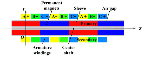
Figure 1.
The structural schematic of the ironless TPMSLM.
2. Motor Magnetic Field Analysis and Analytical Solution
The structural schematic of the ironless TPMSLM is shown in Figure 1. A hole is located at the center of the axially magnetized permanent magnet array, and the primary employs a center shaft fixation method to provide greater rigidity and stability. This design reduces installation difficulties and makes the motor suitable for high-load applications. Additionally, a sleeve surrounds the permanent magnet. The sleeve not only protects and secures the primary but also serves as thermal insulation and vibration isolation, thereby enhancing the motor’s precision and stability.
Since the geometry of the TPMSLM is axisymmetric, only the upper part is selected for analysis to simplify the process. Based on this symmetry, the corresponding analytical model is shown in Figure 2, where is the pole pitch, is the inner radius of the permanent magnet (the radius of the primary center axis), is the outer radius of the permanent magnet, is the inner radius of the secondary coil, and is the outer radius of the secondary coil.
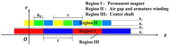
Figure 2.
The subdomain model of the ironless TPMSLM.
2.1. Assumptions
The analytical model shown in Figure 2 was used to analyze the magnetic field of the TPMSLM. To facilitate solving the magnetic field distribution of the TPMSLM, we made the following assumptions [4,28]:
Assumption 1.
The primary of the TPMSLM extends infinitely along the z-direction, causing the permanent magnetic field to vary periodically along the z-axis.
Assumption 2.
Because the primary sleeve, primary center shaft, and secondary shell are made of non-conductive materials, their influence on the permanent magnetic field is negligible.
2.2. Governing Equations
Suppose Assumptions 1 and 2 are considered simultaneously, and the influence of the coil windings on the magnetic field is neglected. In this case, the subdomain model of the motor in the cylindrical coordinate system is shown in Figure 2. It is divided into three regions: the permanent magnet (Region I), the air gap and armature winding (Region II), and the center shaft (Region III).
Based on Assumptions 1 and 2, the air gap magnetic field problem of the TPMSLM can be transformed into a 2-D constant magnetic field problem. For a uniformly magnetized permanent magnet, the internal magnetization currents cancel each other out, so the magnetization current exists only on the surface of the permanent magnet [33,34]. Since all the permanent magnets are axially magnetized, the relationship between the surface magnetization current density and the magnetization strength is expressed as follows [35,36,37]:
According to the distribution of the permanent magnet array shown in Figure 2, an analytical model of the magnetization strength vector distribution is presented in Figure 3, where is the residual magnetization strength of the permanent magnet and is the remanence. Based on Fourier series theory [38], the square-wave magnetization intensity depicted in Figure 3 is expanded into a Fourier series as follows:
where is the harmonic order and .
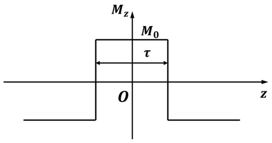
Figure 3.
Spatial distribution curve of magnetization intensity.
Due to the unique tubular structure of the TPMSLM, the vector potential is independent of the coordinates . When the eddy current effect is neglected, based on Maxwell’s equations combined with the Coulomb gauge and constitutive relations, the distribution of the magnetic vector potential satisfies Poisson’s equation in the active region and Laplace’s equation in the passive region, which can be expressed as [39]
According to the definition of vector magnetic potential , the components of the magnetic flux density in the and directions are given by [40]
3. Air Gap Magnetic Field Analysis and Simulation Verification
Based on Assumption 2, Region can be considered equivalent to air. By solving Equation (3) using the method of separation of variables, the general solutions to Laplace’s and Poisson’s equations in each region can be derived as follows:
where , , and are with the coefficients to be solved, and are the first and second types of zero-order modified Bessel functions, respectively, and and are the first and second types of first-order modified Bessel functions, respectively [41].
3.1. Boundary Conditions
Combined with the TPMSLM magnetic field distribution from finite element simulation shown in Figure 4, the boundary condition satisfied by Equation (6) is
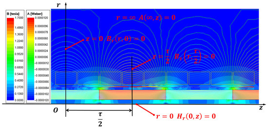
Figure 4.
Magnetic field distribution and boundary conditions of TPMSLM.
In addition, the normal component of the magnetic flux density remains continuous at both the interface between Region I and Region II () and the interface between Region I and Region III (). However, the tangential component of the magnetic field strength exhibits discontinuities at these interfaces due to the abrupt changes caused by the presence of surface currents at the boundary between the permanent magnet and the adjacent regions. The magnitude of this discontinuity equals the tangential surface current density perpendicular to the interface. Therefore, the following boundary conditions apply [37]:
3.2. Analytic Solution of Laplace’s Equation in Region II
Substituting Equations (7) and (8) into Equation (6) yields the expression for the vector magnetic potential in Region II as
where , , and .
Using Equations (4), (5), and (9), the radial and tangential flux density distributions in Region II are as follows:
3.3. Comparison with Axisymmetric FEA
The above analytical method calculates the air gap magnetic field distribution of an axially magnetized ironless TPMSLM. In this section, we perform the FEA of TPMSLMs with varying permanent magnet sizes and verify the accuracy of the analytical method by comparing its results with multiple sets of FEA data.
First, we verify whether the analytical model can maintain high accuracy in predicting the air gap magnetic field at various spatial positions within Region . Figure 5 shows the surface distribution of the radial and tangential flux densities calculated by the analytical method at different spatial positions. Figure 6 compares the analytical results at six different measurement radii () with the radial and tangential flux densities obtained by FEA. The results in Figure 5 demonstrate that the radial and tangential flux densities calculated analytically closely align with the FEA results across different spatial positions within Region .
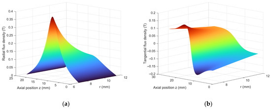
Figure 5.
Flux density distribution curves at various spatial positions: (a) radial flux density; (b) tangential flux density.
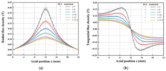
Figure 6.
Comparisons of flux density between the analytical solution and FEA at various spatial positions: (a) radial flux density; (b) tangential flux density.
Figure 7 and Figure 8 are used to verify whether the proposed analytical method can maintain high accuracy in predicting the air gap magnetic field at 2 mm from the outer surface of the permanent magnet, compared with FEA results for different permanent magnet outer diameters . Figure 7 shows the distributions of radial and tangential flux densities calculated using the analytical method for various permanent magnet outer diameters . Figure 8 presents six sets of comparison plots of radial and tangential flux densities obtained from both the analytical calculations and FEA at different permanent magnet radii . The results in Figure 8 demonstrate that the radial and tangential flux densities calculated by the analytical method closely agree with the FEA results across different primary sizes. The analysis of Figure 5, Figure 6, Figure 7 and Figure 8 indicates that the air gap magnetic fields calculated by the analytical method are highly consistent with the FEA results at various spatial locations within Region II and for different primary motor sizes, thereby fully validating the accuracy of the analytical method. Furthermore, analysis of Figure 6, Figure 7 and Figure 8 shows that the air gap flux density curves calculated for the motor at different air gap regions and under varying primary sizes remain within a 5% error margin relative to the FEA curves. The primary cause of the deviation is attributed not only to Assumptions 1 and 2 but also to the demagnetization of the permanent magnet due to the influence of adjacent magnets, resulting in an actual magnetization intensity lower than that assumed in the analytical model.
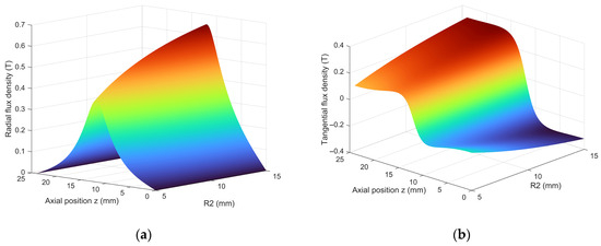
Figure 7.
Flux density distribution curves for different permanent magnet outer diameters: (a) radial flux density; (b) tangential flux density.
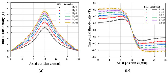
Figure 8.
Comparisons of flux density between analytical solution and FEA under different permanent magnet outer diameters: (a) radial flux density; (b) tangential flux density.
By examining Figure 5 and Figure 6, it is evident that as the measurement radius decreases and approaches the primary, the tangential flux density waveform exhibits greater fluctuations, the radial flux density waveform becomes steeper, and the harmonic content increases. These factors contribute to fluctuations in the linear motor’s back EMF waveform and thrust force. Additionally, the increased harmonic content generates extra heat and noise, which reduce the motor’s performance and lifespan.
By examining Figure 7 and Figure 8, it is evident that a larger radius of the permanent magnet results in smaller fluctuations in the tangential flux density waveform, a more sinusoidal radial flux density waveform, and reduced harmonic content. This occurs because, when measuring the air gap magnetic field 2 mm from the outer surface of the permanent magnet, a larger magnet radius provides a greater effective magnetic pole area, increasing the magnetic field coverage and reducing local magnetic field gradient variations. Consequently, the tangential flux density changes more uniformly, and the radial flux density waveform becomes more sinusoidal. Analysis indicates that, during the design of linear motors, optimizing the radius of the permanent magnets and the air gap thickness can improve the magnetic flux density waveform, thereby enhancing the back EMF waveform, reducing thrust force fluctuations, and improving motor control accuracy.
According to the above analysis, not only is the accuracy of the proposed analytical model and method verified, but the distribution characteristics of the linear motor’s magnetic field are also explored. This reveals the variation pattern of the flux density waveform, which provides valuable guidance for improving the motor’s operational stability and overall performance.
4. Back EMF and Thrust Force Calculations
In this study, the secondary of the TPMSLM consists of the armature winding and the support skeleton. Each phase winding is composed of several groups of coils connected in series/parallel. Figure 9 presents a schematic diagram of the motor winding.
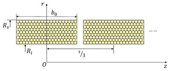
Figure 9.
A schematic diagram of the motor winding.
According to Faraday’s Law of Electromagnetic Induction, the back EMF is induced in each coil as it moves through the radial magnetic field while the primary moves linearly along the z-axis. The back EMF equation for a single-phase winding can be expressed as follows [4,24]:
where is the number of the series turns per phase, is the circumference of the coil at radius , and is the velocity of the secondary. is defined as the th harmonic constant and calculated as
where is defined as the winding factor of the th harmonic, and is the coefficient related to the th harmonic in the radial field distribution and calculated as
Since the coils of each phase winding are positioned relative to the primary in the same manner, assuming a total of pairs of windings, the back EMF of the single-phase winding can be expressed as follows:
where is the back EMF constant.
Similarly, the thrust force generated by the TPMSLM is the Lorentz force produced by the interaction between the armature magnetic field and the permanent magnetic field. The thrust force equation resulting from energizing the phase A winding, when the winding shown in Figure 8 is activated in this position, is as follows:
where is the current through each phase of the winding. Assuming the RMS value of the phase current is , the specific equations are as follows [23,24]:
The total thrust force of the three-phase TPMSLM is as follows:
where is the thrust force constant.
5. FEA, Analytical, and Experimental Verification
A prototype of an axially magnetized, ironless TPMSLM was developed. The main design parameters are presented in Table 2. The air gap magnetic field, back EMF, and thrust force were evaluated through both experimental measurements and FEA of the prototype to verify the accuracy of the analytical formulas. The prototype and test equipment are provided by Qinhuangdao Daze Electromechanical Equipment Co. (Qinhuangdao, China).
Table 2.
The main parameters of the TPMSLM.
5.1. Air Gap Magnetic Field Distribution Validation
The air gap magnetic field of the TPMSLM was measured using the device shown in Figure 10. We placed the Gaussmeter probe against the sleeve ( = 6 mm) and read the radial air gap magnetic flux density at that location. In addition, based on the linear motor module, the Gaussmeter probe was fixed to the secondary, and the host computer controlled the secondary to move along the z-axis at 1 mm intervals to measure the magnetic flux density of the air gap at radii = 6 mm (radial), = 7.3 mm (radial), and = 9.3 mm (tangential) in turn. The radial and axial flux density values can be measured by adjusting the orientation of the Gaussmeter probe.
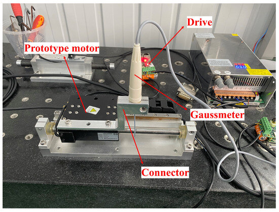
Figure 10.
Schematic diagram of the air gap magnetic field measurement device.
Figure 11 presents a comparison between the measured results and those calculated using the analytical method. As shown, the analytical method’s results closely align with the measured values and waveforms. Apart from inherent errors in the analytical method, deviations may also arise from the Gaussmeter’s measurement accuracy and the experimental conditions.
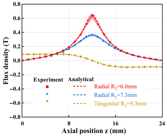
Figure 11.
Magnetic field flux density distribution comparison curve.
5.2. Back EMF and Thrust Force Verification
The experimental platform for the ironless TPMSLM is shown in Figure 12 and consists of a complete machine assembly and a servo driver. The machine assembly includes two prototypes and a thrust sensor. Prototype 1 is energized to drive Prototype 2. An oscilloscope was used to observe the linear back EMF waveform of Prototype 2 operating in generator mode. Additionally, the three-phase back EMF waveform was captured in real time by a high-precision current sensor integrated into the linear motor driver and the internal data acquisition system. The force sensor measures the thrust force curve generated as Prototype 1 drives Prototype 2. This measurement platform further validates the analytical equations derived in the study. The test conditions include an ambient temperature of 25 °C, humidity of 40%, and power ripple below 1%, and the force sensor communicates via the RS485 protocol.
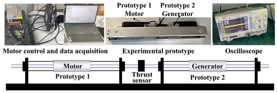
Figure 12.
Linear motor experimental platform.
Figure 13a compares the back EMF curves of the coil windings of Prototype 2 operating in generator mode as it moves axially at a speed of 2.4 m/s. The back EMF waveforms of the three coils are highly consistent. The observed deviations are attributed to the demagnetization of the permanent magnets, manufacturing variations in the prototype, and measurement errors.
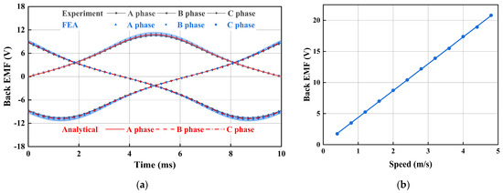
Figure 13.
Comparison of back EMF of three-phase windings: (a) secondary speed of 2.4 m/s; (b) RMS value of back EMF.
Simultaneously, to verify the model’s accuracy across the entire operating range, the peak magnitude of the back EMF was evaluated over a wide speed range of 0 to 4.8 m/s, as shown in Figure 13b. The back EMF demonstrates strong linearity throughout this range.
Figure 14a compares the thrust force curves generated when the motor is powered by a three-phase symmetrical AC current with an effective value of 1 A. The thrust force waveform calculated by the comparative finding analysis method is close to the FE simulation and the measured curve.
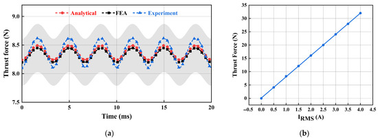
Figure 14.
Comparison of motor thrust force waveforms: (a) input current RMS value of 1 A; (b) thrust force RMS.
Simultaneously, to assess the impact of the armature magnetic field, the thrust magnitude was evaluated over a wide range, up to four times the nominal current value of I = 1 A. As shown in Figure 14b, the thrust demonstrates strong linearity within this range, confirming that the influence of the armature magnetic field on the air gap flux density in the motor under no-load and light-load conditions can be neglected.
Table 3 presents the analytical analysis, FEA, and experimental results for the back EMF and thrust force constants of the TPMSLM. Compared to the FEA and experimental data, the errors in the analytically obtained back EMF and thrust force constants are maintained within 2%. The significant fluctuations observed in the measured thrust force may be attributed to various factors, including friction, processing and assembly errors, mechanical coupling vibrations, and sensor accuracy or signal fluctuations within the test platform itself.
Table 3.
Analysis, FEA, and experimental results.
In analytical calculations, the Fourier series is expanded up to the 20th harmonic. Including higher harmonics and refining the FEA mesh do not significantly improve accuracy. In the 2-D finite element (FE) model, the area is discretized into 3941 units. FE simulation uses Ansys Electronics Desktop 2022 R1, and MTALAB R2022b is used for analytical calculations. Analytical force calculations are approximately 20 times faster (about 3 s) than FE calculations on an Intel® Core™ i5-12500H CPU at 2.50 GHz.
6. Conclusions
In this paper, the magnetic field distribution and electromagnetic properties of a novel ironless TPMSLM are thoroughly analyzed, and a TPMSLM model is selected for experimental and FEA verification. First, an analytical model of the TPMSLM is developed based on EMC within a cylindrical coordinate system, neglecting the influence of the armature magnetic field. An analytical expression for the air gap magnetic flux density of the TPMSLM is then derived. Subsequently, an analytical method for calculating electromagnetic performance parameters, such as back EMF and thrust force, is proposed. To validate the accuracy of the analytical formulas, an experimental prototype was fabricated, and a corresponding test platform was established. The proposed analytical method’s accuracy is confirmed through comparison with experimental results and finite element analysis. Currently, linear motor auxiliary design software based on this analytical method has been developed to support early-stage motor development in industry, significantly reducing the motor research and development cycle.
The proposed analytical method applies not only to the electromagnetic design of this type of motor but also to any motor without an iron in the primary structure. For linear motors with iron in the primary, the magnetic field magnetizes the iron. However, analytical calculations cannot determine the iron’s magnetic permeability or magnetization intensity. Therefore, although the analytical method presented in this article cannot analyze the TPMSLM structure with iron in the primary, it remains a valuable reference for the theoretical analysis of this type of permanent magnet synchronous linear motor. Additionally, this paper does not consider the effects of the armature magnetic field, permanent magnet demagnetization, or eddy current losses, which are important aspects for future improvement of analytical methods.
Author Contributions
Conceptualization, W.S. and P.X.; methodology, W.S.; software, W.S.; validation, B.D., Y.L. and C.L.; formal analysis, W.S.; investigation, Y.P.; resources, H.Z.; data curation, P.X.; writing—original draft preparation, W.S.; writing—review and editing, Y.P.; visualization, W.S.; supervision, Y.L.; project administration, C.L.; funding acquisition, Y.P. All authors have read and agreed to the published version of the manuscript.
Funding
This work was supported by the National Key Research and Development Program of China (2024YFE0114600); the Innovative Talents International Cooperative Training Project of China Scholarship Council (CXXM20240010); the Youth Fund of the Natural Science Foundation of Hebei Province (E2023203007); the Youth Talent Support Program of Hebei Province (BJ2025115); the Yanzhao Golden Platform Talent Recruitment Program of Hebei Province (A2025006); and the Hebei Province Basic Research Program Proof of Concept Project (E2024203259).
Data Availability Statement
The original contributions presented in the study are included in the article, further inquiries can be directed to the corresponding author.
Conflicts of Interest
Pengda Xing, Yang Liu and Hanzhang Zhao were employed by the Qinhuangdao Daze Electromechanical Equipment Co. The remaining authors declare that the research was conducted in the absence of any commercial or financial relationships that could be construed as a potential conflict of interest.
References
- Zong, R.W.; Lin, G.B. Application of Linear Motor in the Urban Rail Transit System (URTS). In Proceedings of the 2015 COTA International Conference of Transportation Professionals (CICTP), Beijing, China, 24–27 July 2015; pp. 1664–1673. [Google Scholar]
- Huang, L.; Yu, H.T.; Hu, M.Q.; Liu, C.Y.; Yuan, B. Research on a Tubular Primary Permanent-Magnet Linear Generator for Wave Energy Conversions. IEEE Trans. Magn. 2013, 49, 1917–1920. [Google Scholar] [CrossRef]
- Souissi, A.; Abdennadher, I.; Masmoudi, A. Analytical Prediction of the No-Load Operation Features of Tubular-Linear Permanent Magnet Synchronous Machines. IEEE Trans. Magn. 2016, 52, 9500507. [Google Scholar] [CrossRef]
- Li, B.; Zhang, J.A.; Shi, Z.P.; Zhao, X.L.; Dong, H. Suppression of Thrust Fluctuation of a New Ironless Tubular Permanent Magnet Synchronous Linear Motor Based on the Halbach Array. Shock Vib. 2021, 2021, 3196773. [Google Scholar] [CrossRef]
- Guo, R.; Yu, H.T.; Xia, T.; Shi, Z.C.; Zhong, W.B.; Liu, X.M. A Simplified Subdomain Analytical Model for the Design and Analysis of a Tubular Linear Permanent Magnet Oscillation Generator. IEEE Access 2018, 6, 42355–42367. [Google Scholar] [CrossRef]
- Chen, F.Y.; Zhang, C.; Chen, J.H.; Yang, G.L. Accurate Subdomain Model for Computing Magnetic Field of Short Moving-Magnet Linear Motor With Halbach Array. IEEE Trans. Magn. 2020, 56, 8200509. [Google Scholar] [CrossRef]
- Yang, Z.H.; Liu, R.; Xia, B. Comparative study of thrust of U-shaped ironless permanent magnet synchronous linear motor based on analytical method and finite element analysis. Int. J. Appl. Electromagn. Mach. 2020, 64, 1091–1101. [Google Scholar] [CrossRef]
- Wu, Q.L.; Wang, L.Q.; Tang, E.L. Structural design and performance prediction of novel modular tubular permanent magnet linear synchronous motor. J. Magn. Magn. Mater. 2022, 564, 170158. [Google Scholar] [CrossRef]
- Ishiyama, N. Linear Motor Equipped with a Stator which is Easily Assembled. U.S. Patent 6,040,642, 21 March 2000. [Google Scholar]
- Zamanian, A.H.; Richer, E. Identification and Compensation of Cogging and Friction Forces in Tubular Permanent Magnet Linear Motors. In Proceedings of the ASME 2017 Dynamic Systems and Control Conference (DSCC), Tysons, VA, USA, 11–13 October 2017. [Google Scholar]
- Nippon Pulse Ltd. Available online: https://www.pulsemotor.com/global/products/LSM.html (accessed on 12 June 2025).
- Wu, S.; Shi, T.; Guo, L.; Wang, H.; Xia, C. Accurate Analytical Method for Magnetic Field Calculation of Interior PM Motors. IEEE Trans. Energy Convers. 2021, 36, 325–337. [Google Scholar] [CrossRef]
- Song, J.-Y.; Lee, J.-H.; Kim, D.-W.; Kim, Y.-J.; Jung, S.-Y. Analysis and Modeling of Concentrated Winding Variable Flux Memory Motor Using Magnetic Equivalent Circuit Method. IEEE Trans. Magn. 2017, 53, 8208905. [Google Scholar] [CrossRef]
- Park, J.K.; Wellawatta, T.R.; Ullah, Z.; Hur, J. New Equivalent Circuit of the IPM-Type BLDC Motor for Calculation of Shaft Voltage by Considering Electric and Magnetic Fields. IEEE Trans. Ind. Appl. 2016, 52, 3763–3771. [Google Scholar] [CrossRef]
- Srikhumphun, P.; Seangwong, P.; Fernando, N.; Siritaratiwat, A.; Khunkitti, P. Design optimization of a novel dual-skewed Halbach-array double-sided axial flux permanent magnet motor for electric vehicles. Sci. Rep. 2025, 15, 25905. [Google Scholar] [CrossRef]
- Li, C.B.; Wang, X.H.; Liu, F.; Ren, J.; Xing, Z.Z.; Gu, X.W. Analysis of Permanent Magnet-assisted Synchronous Reluctance Motor Based on Equivalent Reluctance Network Model. CES Trans. Electr. Mach. Syst. 2022, 6, 135–144. [Google Scholar] [CrossRef]
- Shin, K.-H.; Jung, K.-H.; Cho, H.-W.; Choi, J.-Y. Analytical Modeling and Experimental Verification for Electromagnetic Analysis of Tubular Linear Synchronous Machines with Axially Magnetized Permanent Magnets and Flux-Passing Iron Poles. IEEE Trans. Magn. 2018, 54, 8204006. [Google Scholar] [CrossRef]
- Huang, X.Z.; Li, J.; Tan, Q.; Qian, Z.Y.; Zhang, C.; Li, L. Sectional Combinations of the Modular Tubular Permanent Magnet Linear Motor and the Optimization Design. IEEE Trans. Ind. Electron. 2018, 65, 9658–9667. [Google Scholar] [CrossRef]
- Demirkol, Z.; Hasirci, U.; Demirci, R. Design, Implementation and Test of a Novel Cylindrical Permanent Magnet DC Linear Motor. Energies 2023, 16, 3491. [Google Scholar] [CrossRef]
- Raihan, M.A.H.; Baker, N.J.; Smith, K.J.; Almoraya, A.A. Development and Testing of a Novel Cylindrical Permanent Magnet Linear Generator. IEEE Trans. Ind. Appl. 2020, 56, 3668–3678. [Google Scholar] [CrossRef]
- Li, Z.K.; Wu, L.Z.; Li, Y.X.; Lu, Q.F.; Huang, X.Y.; Peretti, L. Hybrid Analytical Model of Permanent Magnet Linear Motor Considering Iron Saturation and End Effect. IEEE Trans. Energy Convers. 2024, 39, 2008–2017. [Google Scholar] [CrossRef]
- Zhang, Z.J.; Luo, M.Z.; Kou, B.Q.; Luo, C.Q. Design and Analysis of a Trilateral Permanent Magnet Linear Synchronous Motor with Slotless Ring Windings for Transport Systems. In Proceedings of the 2016 IEEE Vehicle Power and Propulsion Conference (VPPC), Hangzhou, China, 17–20 October 2016; pp. 1–6. [Google Scholar]
- Zhang, F.G.; Yin, H.B.; Li, Y.F. Accurate Analytical Models of Armature Reaction Field for Multi-Segment Primaries Ironless PMLSM Based on Subdomain Method. Symmetry 2022, 14, 2091. [Google Scholar] [CrossRef]
- Li, B.; Zhang, J.A.; Zhao, X.L.; Liu, B.; Dong, H. Research on Air Gap Magnetic Field Characteristics of Trapezoidal Halbach Permanent Magnet Linear Synchronous Motor Based on Improved Equivalent Surface Current Method. Energies 2023, 16, 793. [Google Scholar] [CrossRef]
- Lu, Q.F.; Wu, B.C.; Yao, Y.H.; Shen, Y.M.; Jiang, Q. Analytical Model of Permanent Magnet Linear Synchronous Machines Considering End Effect and Slotting Effect. IEEE Trans. Energy Convers. 2020, 35, 139–148. [Google Scholar] [CrossRef]
- Yu, J.Q.; Liu, W.R.; Zhang, Z.; Gao, X.J.; Bao, R.X. Thrust Ripple Suppression Strategy for Precision Machining Platform by Using Predicted Current Sliding Control. Int. J. Precis. Eng. Manuf. 2024, 25, 1987–2001. [Google Scholar] [CrossRef]
- Shin, K.-H.; Cho, H.-W.; Lee, S.-H.; Choi, J.-Y. Armature Reaction Field and Inductance Calculations for a Permanent Magnet Linear Synchronous Machine Based on Subdomain Model. IEEE Trans. Magn. 2017, 53, 8105804. [Google Scholar] [CrossRef]
- Amara, Y.; Barakat, G. Analytical Modeling of Magnetic Field in Surface Mounted Permanent-Magnet Tubular Linear Machines. IEEE Trans. Magn. 2010, 46, 3870–3884. [Google Scholar] [CrossRef]
- Wang, F.R.; Liao, Y.Y.; Chen, J.H.; Zhang, C.; Luo, J.; Ai, Z.Q. Analytical calculation of air gap magnetic field in permanent magnet linear motors. In Proceedings of the 2017 IEEE Conference on Industrial Electronics and Applications (ICIEA), Siem Reap, Cambodia, 18–20 June 2017; pp. 1706–1711. [Google Scholar]
- Rasmussen, K.F.; Davies, J.H.; Miller, T.J.E.; McGelp, M.I.; Olaru, M. Analytical and numerical computation of air-gap magnetic fields in brushless motors with surface permanent magnets. IEEE Trans. Ind. Appl. 2000, 36, 1547–1554. [Google Scholar] [CrossRef]
- Zarko, D.; Ban, D.; Lipo, T.A. Analytical calculation of magnetic field distribution in the slotted air gap of a surface permanent-magnet motor using complex relative air-gap permeance. IEEE Trans. Magn. 2006, 42, 1828–1837. [Google Scholar] [CrossRef]
- Wu, Z.; Zuo, S.; Hu, S.; Hu, X. Analytical modelling of air-gap magnetic field of interior permanent magnet synchronous motors. IET Electr. Power Appl. 2020, 14, 2101–2110. [Google Scholar] [CrossRef]
- Li, Z.K.; Huang, X.Y.; Wu, L.J.; Zhang, H.; Shi, T.N.; Yan, Y.; Shi, B. An Improved Hybrid Field Model for Calculating On-Load Performance of Interior Permanent-Magnet Motors. IEEE Trans. Ind. Electron. 2021, 68, 9207–9217. [Google Scholar] [CrossRef]
- Smeets, J.P.C.; Overboom, T.T.; Jansen, J.W.; Lomonova, E.A. Three-dimensional analytical modeling technique of electromagnetic fields of air-cored coils surrounded by different ferromagnetic boundaries. IEEE Trans. Magn. 2013, 49, 5698–5708. [Google Scholar] [CrossRef]
- Shin, K.-H.; Bang, T.-K.; Cho, H.-W.; Kim, K.-H.; Hong, K.; Choi, J.-Y. Characteristic Analysis of Wave Power Generator Considering Bolting to Fix Permanent Magnet Based on Analytical Method. IEEE Trans. Magn. 2019, 55, 7501805. [Google Scholar] [CrossRef]
- Shin, K.-H.; Lee, J.-H.; Sung, S.; Park, J.-H.; Choi, J.-Y. Electromagnetic Analysis Technique and Experimental Study of Permanent Magnet Synchronous Machine Considering End Effects Using Subdomain Method. IEEE Trans. Magn. 2023, 59, 8103905. [Google Scholar] [CrossRef]
- Gu, Q.S.; Gao, H.Z. Air Gap Field for Pm Electric Machines. Electr. Mach. Power Syst. 1985, 10, 459–470. [Google Scholar] [CrossRef]
- Zhu, Z.Q.; Wu, L.J.; Xia, Z.P. An accurate subdomain model for magnetic field computation in slotted surface-mounted permanent magnet machines. IEEE Trans. Magn. 2010, 46, 1100–1115. [Google Scholar] [CrossRef]
- Park, M.-G.; Choi, J.-Y.; Shin, H.-J.; Lee, K.; Hong, K. Electromagnetic analysis and experimental testing of a tubular linear synchronous machine with a double-sided axially magnetized permanent magnet mover and coreless stator windings by using semianalytical techniques. IEEE Trans. Magn. 2014, 50, 8205204. [Google Scholar] [CrossRef]
- Dreishing, F.; Kreischer, C. Optimization of Force-to-Weight Ratio of Ironless Tubular Linear Motors Using an Analytical Field Calculation Approach. IEEE Trans. Magn. 2022, 58, 7401704. [Google Scholar] [CrossRef]
- Jannot, Y.; Degiovanni, A. Thermal Properties and Measurement of Materials; Wiley-ISTE: London, UK, 2018; pp. 299–300. [Google Scholar]
Disclaimer/Publisher’s Note: The statements, opinions and data contained in all publications are solely those of the individual author(s) and contributor(s) and not of MDPI and/or the editor(s). MDPI and/or the editor(s) disclaim responsibility for any injury to people or property resulting from any ideas, methods, instructions or products referred to in the content. |
© 2025 by the authors. Licensee MDPI, Basel, Switzerland. This article is an open access article distributed under the terms and conditions of the Creative Commons Attribution (CC BY) license (https://creativecommons.org/licenses/by/4.0/).