Abstract
Thin-seam shearers operating in complex coal seams work under adverse conditions with poor visibility, making sensor installation difficult and signal sensing and collection challenging. As a result, identifying the cutting state becomes difficult, which significantly impacts the intelligent control of the shearer’s cutting section. Additionally, the complex working conditions lead to low reliability and shorten the service life of the spiral drum. The spiral drum is a typical symmetrical structure, and its load exhibits both symmetry and nonlinearity. The load under different gangue-inclusion conditions is developed in MATLAB R2022a. The occurrence times and corresponding load-spectrum data of the spiral drum, both under natural wear and sudden impact conditions, are extracted. Analysis reveals that the maximum stress under natural wear conditions exceeds 300 MPa, while under sudden impact conditions it reaches over 600 MPa. Fatigue analysis is carried out with the help of the ANSYS Ncode 2022 R1 module to identify the weak positions of fatigue damage in the spiral drum structure. Reliability models for natural wear and sudden impact failures are established using the Gamma and Weibull distributions, respectively. Parameter estimation is performed, and competing failure reliability models are constructed under independent and correlated conditions of the two failure modes. This approach obtains the competing reliability curve of the spiral drum, providing data support and new ideas for its reliability design.
1. Introduction
Coal is a non-renewable energy source. In China, coal reserves account for over 60% of the country’s total energy reserves [1]. As an essential part of coal resources, thin coal seams have long posed a complex challenge for efficient mining due to narrow mining spaces, complex geological conditions, and harsh working environments [2]. The spiral drum of a shearer, a key component of the cutting section for thin coal seams, uses cutting teeth distributed along its circumference to break, peel, and load the coal–rock working face. It accounts for more than 80% of the shearer’s output power in thin coal seams. The structure of its spiral drum, the helix blade angle, the arrangement of cutting teeth, reliability, etc., all have a significant impact on the working efficiency, cutting performance, and coal-loading capacity of the shearer [3]. Therefore, in-depth analysis of the spiral drum, a key component of the shearer for thin coal seams, can provide a new theoretical basis for designing a new type of shearer spiral drum.
Recent research on shearer spiral drums has advanced through collective efforts in performance modeling, material enhancement, structural optimization, and dynamic analysis. Tian Zhen et al. developed a PSO-BP neural network model that achieves high prediction accuracy with a maximum relative error below 2.61%, providing a reliable basis for determining key design parameters of the shearer [4]. Further investigating operational stability, Hu Denggao et al. compared drums with different pick arrangements to evaluate performance under high-speed rotation [5]. Complementing these studies, Zhang Meichen et al. built an experimental platform based on a two-way coupling method, systematically examining vibration characteristics under various working conditions and proposing a new approach for acquiring operational data [6]. Together, these complementary approaches have substantially enriched the theoretical and practical understanding of shearer spiral drum design and performance.
During coal and rock cutting, shearers for thin coal seams often encounter materials of varying hardness, including gangue, roof, floor, and rock. These can be used to predict coal-mining efficiency and optimize the design of key components. Therefore, some scholars have also researched the identification of coal–rock cutting. In 2000, Tiryaki et al. analyzed the relationship between the shearer’s working efficiency and the vibrations generated during cutting different coal and rock using programming languages such as AutoLISP [7]. In 2022, Liu Chunsheng et al. established a load characteristic and correlation model for cutting coal and rock, enabling more accurate calculation of the cutting load [8]. In 2023, Li Yiming et al. from Beijing Information Science and Technology University proposed a method for identifying caving coal and rock based on wavelet packet fuzzy entropy and KL divergence, using the vibration signals of the rear tail beam of the hydraulic support impacted by caving coal and rock collected at the entirely mechanized caving mining site. This method significantly accelerated the time for coal–rock identification [9]. In addition, reliability issues also need to be taken into account. In 2019, Leonid Tiokhin found, through model-based evaluation, that rewarding early discovery would lead to a cultural evolution within the research community toward conducting research with smaller samples, thereby reducing research reliability and the information value of the average study [10]. In 2021, Leoni et al. mitigated the negative impacts of competition by increasing the start-up costs of a single study and increasing the returns of secondary results. In 2023, Guangze Pan et al. proposed a general reliability analysis method that accounts for complex, mixed-correlated competition scenarios [11]. In 2024, J. Hammond proposed a data-driven reliability analysis framework that uses sliced normal distribution to construct a probability model for uncertain parameters [12]. This method accounts for errors introduced by using the distribution to model the dataset and demonstrates good distributional robustness.
In practical work, most systems or products fail due to natural degradation or sudden shock. In such cases, for products composed of multiple components where some components experience both natural degradation failure and sudden shock failure, whether the failure is caused by the combined effect of the two—that is, the competing failure of multiple failure modes—has become a key research direction for domestic and foreign experts and scholars in recent years. One of the referenced studies considered two interrelated failure processes and proposed two different failure forms: soft failure, jointly caused by continuous degradation and sudden degradation damage resulting from the shock process; and hard failure, caused by sudden stress following the same shock process [13]. In 2021, Wang Xingang proposed an analysis method for competing failures between multiple failure modes and sudden failures, which solved the reliability assessment problem for aero-engines [14]. In 2022, Qin Yankai et al. proposed multiple competing reliability models for the degradation forms of cutting teeth under soft and hard failure situations, providing a theoretical basis for the design optimization of cutting teeth [15]. In 2023, LU Hao established a competing reliability model to analyze the competition between natural wear failure and sudden shock failure of gears under multi-parameter changes, and verified the model’s accuracy through an engineering example [16]. In 2024, Zhang Wei et al. established a competing reliability model for network-connected electricity meters at a high-temperature, arid, and hot typical environmental test base, providing a theoretical basis for the reliability assessment of small-sample datasets [17].
To address the issues of difficult sensor installation, signal sensing and acquisition, and the low reliability and short service life of the auger drum in shearers, this paper builds a coal–rock cutting test bench to conduct physical experiments and obtain data from a real prototype. The spiral drum is a typical symmetrical structure, and its load exhibits both symmetry and nonlinearity. Using MATLAB R2022a the load characteristics under different gangue-inclusion working conditions are simulated. Then, a three-dimensional model of the spiral drum is constructed, and the ANSYS 2022 R1 finite-element analysis and ANSYS Ncode 2022 R1 fatigue module are used to simulate the cumulative fatigue damage of the spiral drum on the shearer for thin coal seams. Finally, by combining stochastic process theory with the competing reliability model and comparing the resulting reliability curves, the accuracy of the established model is verified, providing a method for maintaining and supporting the shearer’s spiral drum.
2. Overall Scheme for the Competing Reliability Analysis of the Spiral Drum of Shearer for Thin Coal Seams
2.1. Technical Route
For the competing reliability analysis of the spiral drum of a shearer for thin coal seams, finite-element simulation and fatigue analysis are carried out with the help of ANSYS 2022R1 software. A reliability model is established to analyze the spiral drum’s reliability under multiple failure modes. The overall scheme is shown in Figure 1.
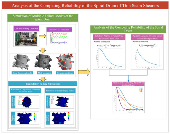
Figure 1.
Overall scheme used for competitive reliability analysis of spiral drum in a thin-coal-seam shearer.
2.2. Scheme Design
- (1)
- Analysis of the Spiral Drum: Build a coal–rock cutting test bench. By conducting physical experiments, real-world physical prototype data can be obtained. In MATLAB R2022a software, simulate random loads for four gangue-inclusion scenarios. The situations of the four working conditions are as follows: Condition 1: medium-hardness gangue (Protodyakonov strength coefficient f =3.5); Condition 2: high-hardness gangue (f = 5.4) with significantly increased gangue hardness; Condition 3 (composite condition): simulation of cutting picks successively engaging two rock layers of different hardnesses (f = 3.5 and f = 5.4) within a single drum rotation; Condition 4 (specific location condition): gangue with the same hardness as Condition 1 (f = 3.5) but confined to a narrower cutting zone, enabling analysis of how gangue geometry affects impact load characteristics and force spectrum.
- (2)
- Simulation of Multiple Failure Modes of the Spiral Drum: Firstly, construct the three-dimensional model of the spiral drum, conduct mesh generation, and set boundary conditions to establish the simulation foundation. Use ANSYS 2022 R1 software to perform finite-element simulations and fatigue analyses for natural wear degradation and sudden shock failure, and to identify the part with the maximum fatigue damage. This can provide accurate data for the next-step reliability analysis.
- (3)
- Competing Reliability Analysis of the Spiral Drum: Build reliability analysis models for natural wear failure, sudden shock failure, the failure forms where the two are independent of each other, and the competing failure forms where the two are interrelated. Use the maximum likelihood and least-squares methods to estimate the model parameters. Based on the cumulative fatigue damage value data, perform parameter calculations using MATLAB R2022a software to obtain the reliability curves of the spiral drum of the shearer for thin coal seams. Conduct a comparative analysis of the reliability of the shearer’s spiral drum according to the obtained reliability curves.
3. Simulation Analysis of the Spiral Drum of Shearer for Thin Coal Seams
The occurrence times of the natural wear degradation process, caused by cutting pure coal, and the sudden shock failure degradation process, caused by changes in the spiral drum’s cutting hardness during the cutting of thin coal seams, can be determined. When the spiral drum experiences natural wear degradation failure, the load spectrum shows a stable periodic cycle. When sudden shock failure occurs, the load spectrum will present short-term and extensive load data. The magnitudes and occurrence times of the loads during sudden shock failure differ. In the next step, based on the obtained cutting-state identification results, the required load spectrum is derived, providing data support for the subsequent simulation of the spiral drum’s cumulative fatigue damage for thin coal seams.
3.1. Simulation of Dynamic Random Loads Under Working Conditions of Coal Seams Containing Gangue
The simulation of instantaneous dynamic loads is crucial for the reliability analysis of the shearer spiral drum in coal seams containing gangue. Building a test system to evaluate the physical and mechanical properties of samples and test the properties of coal-seam-with-gangue samples in accordance with national standards is a key step in constructing the rigid–flexible coupling virtual prototype model of the shearer [18]. Based on the GBT23561 standard [19], coal–rock specimens were obtained. A coal block measuring approximately 50 cm × 50 cm × 50 cm was extracted along the coal–rock bedding plane. A DQ-1 rock cutting machine was selected to test the compressive strength of the coal–rock. The Protodyakonov strength index of the coal–rock was determined using the standard drop weight method. The density of the coal–rock was measured using a pycnometer and the drying method. A wire-wound resistance strain gauge with a resistance of 120 ohms and a gauge size of 3 mm × 20 mm was selected. The strength of the coal–rock was tested using a WDW-100E microcomputer-controlled electronic universal testing machine (Jinan Shijin Group, Jinan, China). The physical and mechanical parameters of the coal–rock were tested. The coal blocks were fixed to the ground to simulate a real coal seam. A physical prototype of the shearer cutting part was established. Compared to the overall machine model, focusing solely on the shearer spiral drum made it easier to measure loads during operation. Acceleration sensors were arranged on the spiral drum, and signals were transmitted to a terminal computer through an internal circuit. The physical prototype of the shearer spiral drum began cutting the coal block, and the obtained data was saved to the terminal computer [20]. The model of the coal–rock cutting test bench is shown in Figure 2.
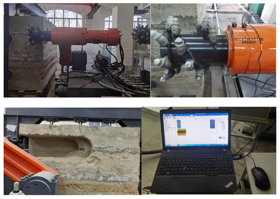
Figure 2.
Coal–rock cutting test bench.
The coal–rock cutting test bench can provide data from a physical prototype, which serves as a basis for subsequent numerical simulations of loads.
The simulation of instantaneous dynamic loads is crucial for the reliability analysis of the shearer’s spiral drum in coal seams with gangue. Building a test system for the physical and mechanical properties of specimens and testing the properties of coal-seam-with-gangue specimens in accordance with national standards are key steps in constructing the rigid–flexible coupling virtual prototype model of the shearer. Based on the gangue-inclusion conditions of the working face in the Ordos Coal Mine where the shearer operates, and in combination with the research group’s “Shearer Instantaneous Load Numerical Simulation Software (2014SR102903)”, the instantaneous loads on the spiral drum of the shearer during the gangue-cutting operation are numerically simulated. The specific process is shown in Figure 3.
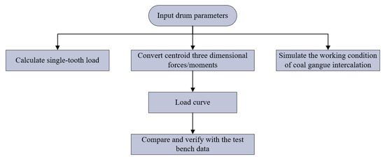
Figure 3.
Flowchart of load numerical simulation.
Using the basic parameters of the shearer’s spiral drum, calculate the single-tooth load of each cutting tooth on the spiral drum in MATLAB R2022a software. Transform the obtained forces towards the centroid of the spiral drum. Then, calculate the three-dimensional forces and three-dimensional moments of the spiral drum, respectively, as shown in Figure 4.
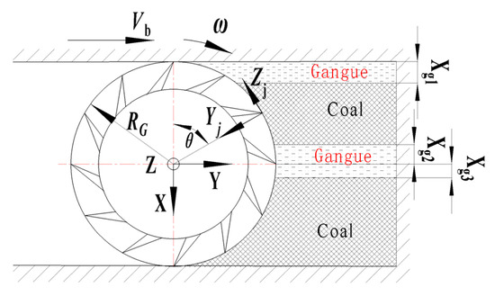
Figure 4.
Spiral drum’s force analysis.
In the equation, represents the total number of cutting lines. In this paper, it is taken as 2.
The expression for the additional axial force of the spiral drum is
In the equation, represents the additional axial force, ; is the distance from the rear-guiding sliding pin to the center of the end-face of the drum, close to the coal-seam side, ; is the distance between the guiding slide rails, ; is the maximum deflection angle of the shearer when cutting into the coal wall, ; is the cutting-force increase coefficient.
The expression for the resultant moment of the drum in the X-direction is
The expression for the resultant moment of the drum in the Y-direction is
The expression for the resultant moment of the drum in the Z-direction is
In the equation, is a distance from the i-th cutting line to the centroid, .
Due to the highly complex conditions in coal seams, numerical simulations of spiral drum loads must also account for the presence of gangue and other substances. In this paper, objects other than coal-enclosed substitute bodies are used to replace rock. Four different gangue-inclusion states determine the size and position of the enclosed bodies. In MATLAB R2022a, the major and minor axis diameters of the enclosed bodies are input to conduct digital simulations of the four gangue-inclusion working conditions.
The load on the auger drum arises from the cutting action of the picks on the coal–rock. Since the cutting process of picks on coal–rock is characterized by intermittent engagement, the load on the auger drum exhibits discontinuous, nonlinear, and time-varying characteristics. Due to the circumferential motion pattern of the spiral drum and the discontinuous cutting method of the picks, the dynamic load exhibits a certain periodic motion characteristic. The periodic motion parameters of the spiral drum are listed in Table 1.

Table 1.
Spiral drum motion parameters.
The curves of the three-dimensional forces and moments of the shearer’s spiral drum under a specific gangue-inclusion working condition are shown in Figure 5.
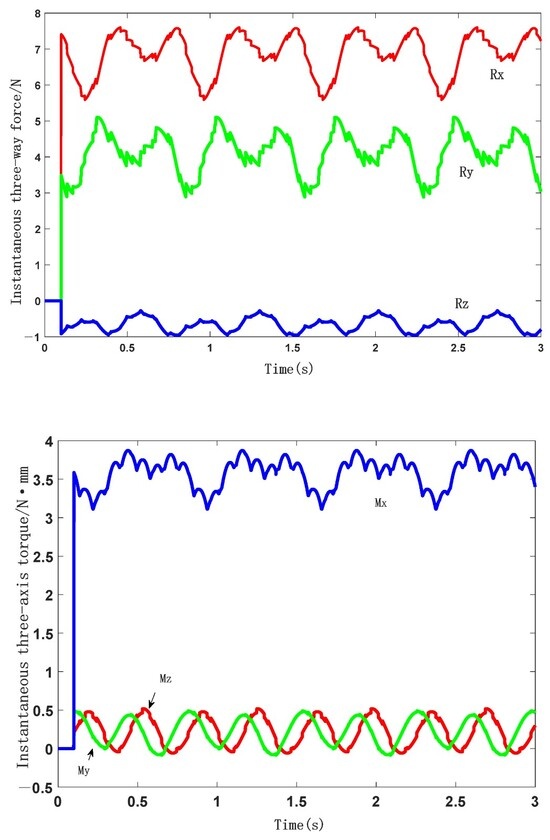
Figure 5.
Three-way force and three-way torque of the spiral roller in a particular state of dirt separation.
As shown in Figure 5, the maximum instantaneous forces in the x, y, and z directions acting on the shearer’s spiral drum are 75,994.6845 N, 50,997.7082 N, and 9568.0119 N, respectively. The instantaneous moments in the x, y, and z directions acting on the shearer’s spiral drum are 5,170,398.8412 , 4,884,076.7957 , and 38,736,814.4337 , respectively. By constructing a test bench to measure the load conditions of the shearer’s spiral drum and comparing them with numerical simulation results, it is found that the results are highly reliable. Therefore, it is reliable to use the data obtained from the numerical simulation for the next-step analysis.
3.2. Calculation of Single Tooth Load of Spiral Drum for Thin-Seam Shearer
During the process of a thin-seam shearer’s spiral drum cutting pure coal, the cutting teeth on the spiral drum are regularly distributed when cutting coal–rock. Thus, different cutting teeth are subjected to different forces at the same time. In the simulation calculations, troops concentrated in the centroid direction must be decomposed onto each cutting tooth. Using MATLAB R2022a to derive mathematical formulas and applying the principles of theoretical and material mechanics, the three-dimensional forces and moments acting on each cutting tooth can be calculated. These are used as the load spectrum for the static simulation in Ansys-Workbench 2022 R1 software. The distribution of the cutting-resistance load on a single cutting tooth of the drum is generally considered to follow a Rayleigh distribution with [21]. Therefore, the expression of the random cutting resistance that the cutting teeth of the shearer’s spiral drum are subjected to during the coal–rock cutting process is shown in Equation (6):
In the equation: represents the average value of the cutting resistance; represents the mean-square deviation of the cutting-tooth cutting resistance under the Rayleigh distribution. Two independent normal random processes can express the Rayleigh random process, and its expression is [22]
In the equation, and , respectively, represent independent normal random processes with a mean of 0, a standard deviation of 1, and a standard correlation function of ; is a step size.
From this, the cutting resistance that the cutting tooth experiences when cutting coal–rock is
In the equation, is a step distance of the random process, ; and are independent normal random processes.
The traction resistance of the cutting tooth is
In the equation, . is a mean-square deviation of the traction resistance of the cutting tooth. is an independent, typical random sequence.
The lateral force of the cutting tooth is
In the equation, . represents the mean-squared deviation of the lateral force of the cutting tooth. is an independent, typical random sequence.
Therefore, in MATLAB R2022a software, the numerical values of the three-dimensional forces and three-dimensional moments of the shearer’s spiral drum obtained from numerical simulation can be disassembled and calculated for single-tooth loads. The loads on the centroid of the spiral drum are calculated in the form of a Rayleigh distribution, and the simulated data are exported to an Excel spreadsheet. The single cutting tooth loads corresponding to the four gangue-inclusion working conditions are extracted at a step size of 0.05 s. Eventually, four sets of load-spectrum data are obtained. The three-dimensional forces and moments acting on each cutting tooth in the four datasets are recorded accordingly. In a static structural simulation analysis using finite-element software, it is necessary to align with the coordinate-axis directions; otherwise, significant errors may occur in the experimental results. Therefore, proper data processing is essential.
3.3. Simulation of the Natural Wear and Degradation Failure of the Spiral Drum of the Thin-Coal-Seam Shearer
When a thin-seam shearer is in operation, it is in the normal coal–rock cutting state for most of the time. The three-dimensional forces and three-dimensional moments acting on the cutting teeth fluctuate over time. However, the damage to the cutting teeth is relatively less significant than that caused by sudden impact wear. In this working state, the spiral drum experiences minor vibration and damage, thereby extending its service life. This is also the leading cause of fatigue damage to the cutting teeth. By simulating and calculating cumulative fatigue damage due to natural wear, accurate data can be provided for the next-step reliability analysis. The raw load signals obtained from physical tests and numerical simulations were processed by decomposing the total load acting on the centroid of the drum into individual cutting picks. This generated load spectra for each pick, which were used for subsequent finite element static simulations and ANSYS Ncode 2022 R1 fatigue analysis. The specific simulation process is shown in Figure 6.
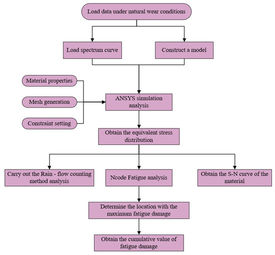
Figure 6.
Flowchart of simulation for failure due to natural wear and degradation.
3.3.1. Finite Element Simulation of the Spiral Drum of Shearer for Thin Coal Seams
The static dynamics analysis of the spiral drum of a thin-seam shearer is first performed using a single dataset of natural wear and degradation.
Using Ansys-Workbench 2022 R1 finite-element analysis software, conduct a static structural analysis (static structural). The spiral drum model in the rigid–flexible coupling model of the thin-seam shearer is saved as a model, with the file format changed to x-t so that it can be used for simulation analysis in the finite-element software. The spiral drum model is shown in Figure 7. In the Engineering Data module’s material library, open the engineering data source module and select the ANSYS Ncode 2022 R1 material library. In the ANSYS Ncode 2022 R1 database, there are more material types with more complete information attributes, which will be beneficial for fatigue analysis in the next step. Also, the material types in the library are more in line with the actual situation. Therefore, select the Cr-Mo steel alloy material that meets the strength requirements of the cutting teeth of the shearer’s spiral drum and add the material to the material library of the finite-element analysis. The material parameter attributes are shown in Table 2.
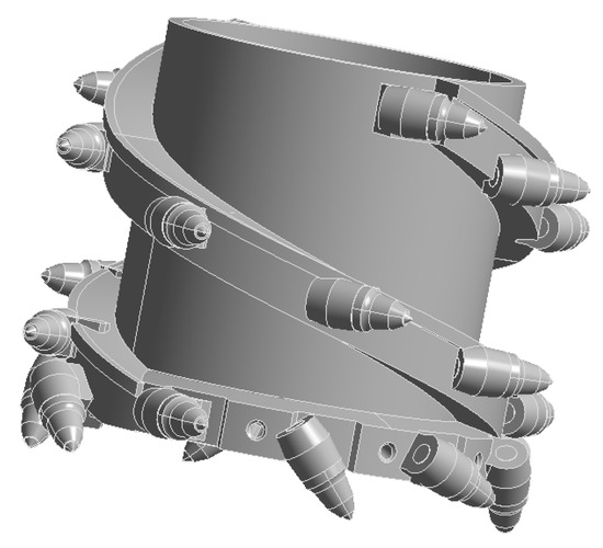
Figure 7.
Spiral drum model.
Table 2.
Material properties of CR-Mo steel.
In the mechanical finite-element static structural analysis system, assign the material to the spiral drum of the thin-seam shearer. After a successful operation, a checkmark will appear in the left-hand toolbar, indicating that the material has been assigned to the shearer’s spiral drum. When using ANSYS 2022 R1 for finite-element analysis, the first step is to generate a finite-element mesh of the model. The quality of meshing directly affects the accuracy of the calculation model. In finite-element simulation of mechanical structures, tetrahedral meshes (tetrahedra) are usually used. The adjustment to the mesh structure is made using the “Method” property. Since the spiral drum model of the thin-seam shearer is relatively complex, the automatic near-edge refinement option must be selected. To improve mesh accuracy, set the mesh size to 50 mm with the medium-quality setting. Only after these operations are completed can the meshing be carried out. The mesh results are shown in Figure 8. After meshing, there are 73,890 nodes and 41,530 elements.
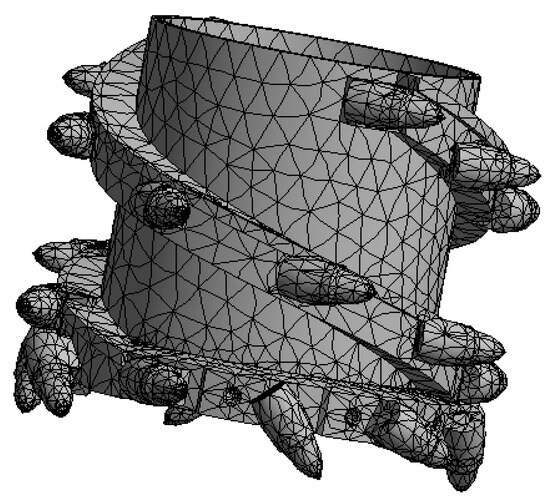
Figure 8.
Grid division.
Before solving the finite-element simulation of the shearer’s spiral drum, it is also necessary to apply constraints to the model. From the physical prototype of the spiral drum, it can be seen that the spiral drum performs coal–rock cutting operations driven by the rocker arm shaft. The spiral drum is fixed through a total of 16 bolt holes and a central shaft. Therefore, the selected constraint method is to apply constraints on the inner surfaces of the 16 bolt holes and the inner surface of the main-shaft position. To meet the actual working requirements, the remote-end constraint method is selected to restrict the translational degrees of freedom of the spiral drum in the x, y, and z directions and the rotational degrees of freedom in the x and z directions. Set the centroid of the spiral drum as the constraint point for the spiral-drum model, and set the rotational degree of freedom of the spiral drum around the y-axis to 360°. The result after setting is shown in Figure 9.
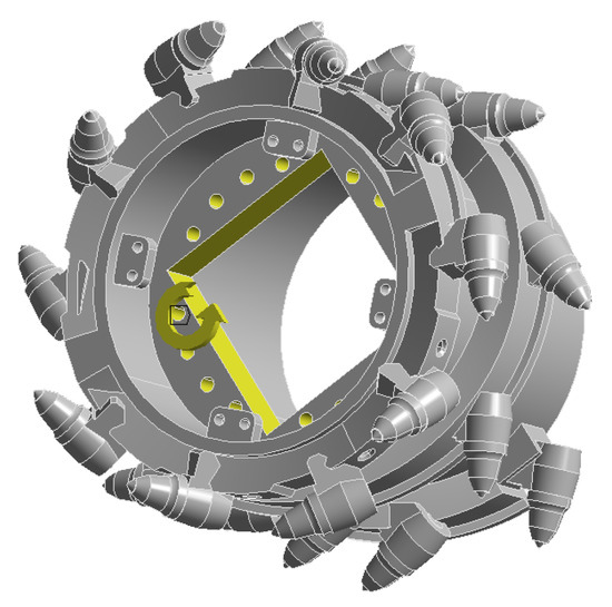
Figure 9.
Set constraints.
Based on the data of the three-dimensional forces and three-dimensional moments of a single cutting tooth calculated by Equations (6)–(10), use ANSYS 2022 R1 software to apply the three-dimensional force and three-dimensional moment loads on the cutting teeth of the shearer’s spiral drum. The directions of the three-dimensional forces and three-dimensional moments of each cutting tooth are shown in Figure 10.
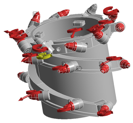
Figure 10.
Directions of the three-way force and torque.
After the finite-element static structural simulation, the contour map of equivalent elastic strain is obtained. The ANSYS 2022 R1 static stress simulation result contour map is shown in Figure 11, and the equivalent stress received by the cutting tooth is 307.39 MPa. This is because the cutting pick is the direct component interacting with the coal–rock, and the maximum stress occurs precisely at the pick. Due to the complex distribution of coal–rock strata, the serial number of the cutting pick subjected to the maximum stress corresponds to the one in contact with harder coal–rock sections. The cutting tooth will suffer fatigue damage after being impacted. In the next step, using ANSYS Ncode 2022 R1 fatigue analysis, the fatigue damage to the cutting tooth is simulated and calculated. The other four working conditions are subjected to static simulation calculations in the same manner and are assigned the same four gangue-inclusion working conditions.
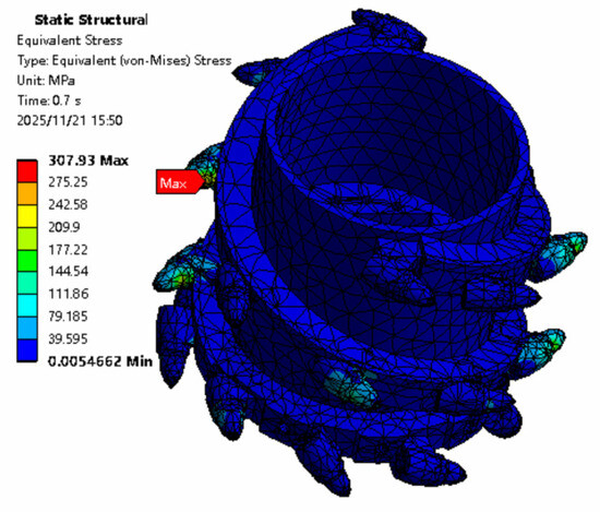
Figure 11.
Cloud image of natural wear equivalent stress results.
3.3.2. Fatigue Analysis of the Spiral Drum of Shearer for Thin Coal Seams
The ANSYS Ncode 2022 R1 module in the Workbench is used to conduct fatigue analysis of the spiral drum on the thin-seam shearer. The solution is obtained through the high-cycle-fatigue module’s time series (ANSYS Ncode 2022 R1 SN Time Series) and the static structural finite-element stress analysis results of the shearer’s spiral drum. The principle of ANSYS Ncode 2022 R1 fatigue analysis is to decompose the stress spectrum using the rain-flow counting method, then load it over time, and finally analyze it using the Miner fatigue damage accumulation theory.
The material properties of Cr-Mo steel can be obtained from the ANSYS Ncode 2022 R1 material library, and its S-N curve is shown in Figure 12. After completing the loading of material property mapping (Edit Material Mapping) and load-application mapping (Edit Load Mapping) in the Stress Life-Analysis module, the solver is set as the S-N curve engine. In the Fatigue-Results-Display module of ANSYS Ncode 2022 R1 fatigue analysis post-processing, the selected result type is set to the fatigue damage value (Damage) to obtain the required fatigue damage value. The fatigue damage analysis results and process of the spiral drum of the thin-seam shearer are shown in Figure 13 and Figure 14.
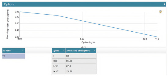
Figure 12.
S-N curve of the material.
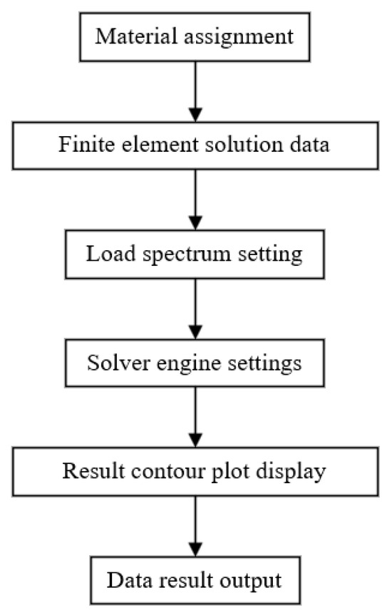
Figure 13.
Fatigue damage simulation flowchart.
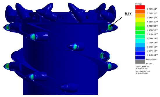
Figure 14.
Cloud image of fatigue damage caused by natural wear.
As shown in Figure 14, during the natural wear and degradation process, the maximum cumulative fatigue damage of the shearer’s spiral drum is 1.853 × 10⁻⁷, which occurs at node 27,349. The minimum fatigue damage value is 0, indicating that the structure has not suffered fatigue damage. Since the analysis object is the entire shearer’s spiral drum, it is reasonable that some parts of the structure have not experienced fatigue damage. The remaining three gangue-inclusion working conditions are simulated, and the cumulative fatigue damage value is calculated in the same way and using the same process. The cumulative fatigue damage values under the four working conditions are shown in Table 3.
Table 3.
Cumulative fatigue damage values under four operating conditions.
Scenario 3 shows the highest fatigue damage (2.428 × 10⁻⁷) due to unfavorable gangue positioning causing concentrated stress. Scenario 2 demonstrates the lowest damage (1.483 × 10⁻⁷) from favorable load distribution. Scenarios 1 and 4 exhibit intermediate values (1.853 × 10⁻⁷, 2.108 × 10⁻⁷), reflecting transitional severity. These variations in load spectra under different gangue conditions capture mining complexities and support reliable competing failure modeling. The obtained fatigue damage values are recorded and substituted into the reliability analysis and used to calculate the shearer’s spiral drum in the next part.
3.4. Simulation of Sudden Impact Failure of the Spiral Drum of a Thin-Seam Shearer
During the process of cutting teeth, cutting coal, and rock, and when cutting objects such as gangue with a hardness higher than that of coal and rock, the cutting teeth are impacted, resulting in significant cumulative fatigue damage. When the external impact—the effect on the cutting teeth—exceeds their yield strength, the cutting teeth are damaged. In this case, the cutting teeth need to be replaced promptly to avoid affecting the spiral drum’s working efficiency. In this study, the state that directly causes the damage to the cutting teeth is not considered. Only the state in which the cutting teeth are exposed to a significant impact when cutting the gangue, roof, or floor, but are not directly damaged, is considered; that is, the state where the cumulative fatigue damage value caused to the cutting teeth is much higher than that caused by natural wear. In the following text, one of the identified sudden impact failure states is taken as an example to simulate and calculate the cumulative fatigue damage value of the cutting teeth under sudden impact.
3.4.1. Finite Element Simulation of the Spiral Drum of a Thin-Seam Shearer
The steps are the same as those in the simulation of natural degradation failure. When applying three-dimensional forces and moments, replace the load spectrum for natural wear-out failure with that for the sudden-impact state. Export the load data according to the time and apply it to the cutting teeth of the shearer’s spiral drum with corresponding numbers. Under the influence of the sudden-impact load, select the moment when the cutting teeth of the shearer’s spiral drum are subjected to the maximum load; that is, set the time step to 1. The cutting teeth are affected by three-dimensional moments and forces within a single time step. The resulting contour map of the equivalent stress is shown in Figure 15. The maximum value of the equivalent stress is 681.68 MPa, which does not exceed the yield strength of the material and will not cause damage to the cutting teeth. Therefore, the simulation results are reliable and authentic.
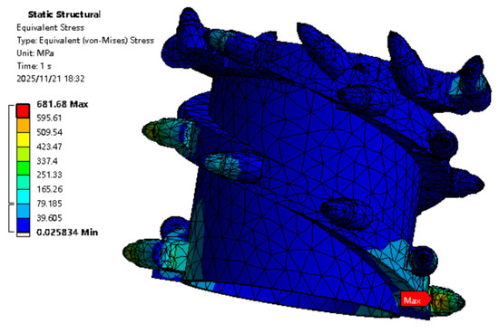
Figure 15.
Cloud diagram of equivalent stress results of sudden impact.
3.4.2. Fatigue Analysis of the Spiral Drum of a Thin-Seam Shearer
In the ANSYS Ncode 2022 R1 fatigue analysis software, the method for importing the material mapping is the same as in the fatigue damage simulation for the natural wear state. In the load mapping, since there is only one load step, select the constant-amplitude load mapping (Constant Amplitude) in ANSYS Ncode 2022 R1. That is, during the loading process, the amplitude remains constant, and the amplitude coefficient is taken as 1. The load-mapping settings are shown in Figure 16.
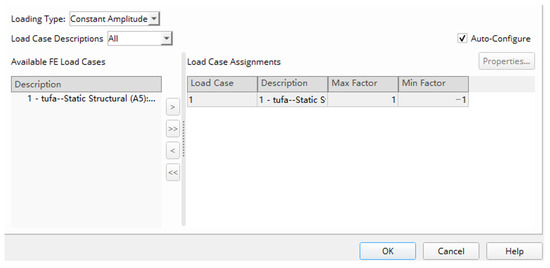
Figure 16.
Load-mapping settings.
After the settings are complete, the fatigue damage value can be obtained by selecting “Damage” from the post-processing options. The cumulative fatigue damage contour map of the shearer’s spiral drum under the sudden-impact state is shown in Figure 17.
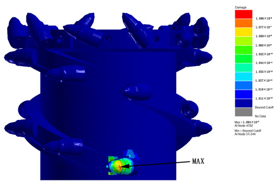
Figure 17.
Cumulative cloud image of fatigue damage under sudden impact conditions.
As shown in Figure 17, the maximum fatigue damage of the shearer’s spiral drum in the sudden-impact state is 1.086 × 10⁻⁶. As indicated in the contour map, the fatigue damage to the No.1 cutting tooth of the shearer’s spiral drum is significant, with the maximum fatigue damage occurring at the connection between the cutting tooth and the cutting line. This is because, within the selected time period, the torque experienced by the cutting tooth causes a large torsional force at the connection between the cutting tooth and the cutting line. This force leads to fatigue damage at the root of the cutting tooth until it breaks, which is also the most common failure mode of the cutting teeth of the shearer’s spiral drum. The cumulative fatigue damage values for the other groups in the sudden-impact state are shown in Table 4.
Table 4.
Cumulative value of fatigue damage during sudden impact.
The loads during the shearer’s spiral drum operation follow a Rayleigh distribution. The calculated three-dimensional forces and three-dimensional moments of the shearer’s spiral drum are decomposed onto each cutting tooth. Based on the natural wear and sudden-impact moments identified from the cutting results, the required load data for each group is exported and saved in an Excel spreadsheet. Using Ansys-Workbench 2022 R1 software, a static finite-element simulation of the shearer’s spiral drum is carried out. Based on the load data for the four gangue-inclusion states, four sets of static structural finite-element simulations are conducted for natural wear and four for sudden impact. The equivalent stress in the natural wear state is concentrated around 300 MPa, whereas in the sudden-impact state, it is focused around 600 MPa. The ANSYS Ncode 2022 R1 fatigue analysis software is used to simulate the cumulative fatigue damage for the eight datasets after the finite-element simulation. After adjusting the settings, the resulting contour maps of the cumulative fatigue damage values for each group are obtained. The part with the most significant fatigue damage is the connection between the cutting tooth and the cutting line, with a maximum fatigue damage value of 8.972 × 10⁻⁶. This is the same as the position where the fatigue damage of the cutting teeth of the shearer’s spiral drum is most likely to occur under actual working conditions. Therefore, the simulation calculation of the cumulative fatigue damage value of the cutting teeth of the shearer’s spiral drum in this chapter is reliable. The obtained data can be introduced into the reliability analysis of the shearer’s spiral drum in the next chapter, providing a solid data foundation.
4. Establishment of the Competing Reliability Model for the Spiral Drum of a Thin-Seam Shearer
Based on simulation-derived fatigue damage values for the shearer’s spiral drum, a reliability model is constructed. Parameter estimation yields model parameters for generating reliability curves. The reliability of the shearer’s spiral drum is judged from these curves. By comparing the reliability curves under different failure modes, the correctness of the established competing reliability model is verified.
4.1. Assumptions of the Competing Reliability Model for the Spiral Drum
To simplify the actual and complex working conditions of the shearer’s spiral drum, this thesis now makes the following necessary assumptions for the model [23]:
- It is assumed that when the cutting teeth of the shearer’s spiral drum fail, there are only two failure modes: sudden degradation failure and natural wear degradation failure. Moreover, the failure of the cutting teeth of the shearer’s spiral drum is caused by the competition between these two failure forms.
- The relationship between the probability of sudden failure of the cutting teeth of the shearer’s spiral drum and the amount of performance degradation (cumulative fatigue damage value) of the cutting teeth is unknown. They may be related or unrelated to each other.
- The fatigue damage process of the cutting teeth of the shearer’s spiral drum is irreversible. The cumulative amount of fatigue damage of the cutting teeth is in a directly proportion relationship with time, and the cumulative amount of fatigue damage of the cutting teeth at the initial moment is 0.
- The cumulative amount of fatigue damage of the cutting teeth of the shearer’s spiral drum is a random variable, and its value corresponding to time is .
- The total fatigue damage amount of the cutting teeth of the shearer’s spiral drum is a constant , which does not change with time. Generally, when the total fatigue damage amount of the cutting teeth of the shearer’s spiral drum approaches 0.9, the cutting teeth of the shearer’s spiral drum need to be replaced or repaired [24].
4.2. Establishment of the Competing Reliability Model for the Spiral Drum
4.2.1. Natural Wear Degradation Failure Model
The primary failure mode of the shearer’s spiral drum cutting teeth is wear. During the operation of the shearer, as the cutting teeth cut coal and rock along with the rocker arm, they are primarily in the state of cutting pure coal. The cutting teeth only receive the reaction force from the coal and rock, resulting in a small and stable degradation amount of the cutting teeth of the shearer’s spiral drum; that is, the fatigue damage value is small and stable, and the fatigue damage value accumulates over time, following a monotonically increasing pattern. Suppose the time is divided into intervals and , where . The fatigue damage values of the cutting teeth of the shearer’s spiral drum in these two intervals are independent of each other; that is, the fatigue damage conditions of the spiral drum cutting teeth in the two intervals do not interfere with each other. This characteristic of independent increments enables the separate analysis of natural wear across different time periods, greatly simplifying the study of the entire wear process of the shearer’s spiral drum cutting teeth. At the same time, due to many influencing factors such as the coal–rock cutting part, cutting speed, and the arrangement of the cutting teeth on the drum, considering the individual differences in the cutting teeth of the shearer’s spiral drum during the natural degradation and wear process, and the cumulative amount of fatigue damage of the cutting teeth of the shearer’s spiral drum per unit time are independent non-negative values, which conform to the non-negative strictly monotonic process of the Gamma process. Therefore, the Gamma process can be used to describe the natural wear degradation process of the shearer’s spiral drum; that is . Among them, is a non-negative value representing the cumulative fatigue damage value of the shearer’s cutting teeth, is a shape parameter, and is a location parameter. Its probability density function is
Therefore, the reliability function of the natural wear degradation failure of the shearer’s spiral drum is
In the equation, represents the time of degradation failure; is an intermediate variable in the integral calculation; and is a failure probability when only degradation failure is considered.
Using the Gamma process to describe the natural wear degradation failure mode of the shearer’s spiral drum can better model its wear conditions across different time periods. Moreover, it allows inference of wear conditions over longer time intervals from the wear of the cutting teeth over shorter time periods. The Gamma process’s positive nature can prevent unreasonable results, such as negative wear amounts that do not reflect actual working conditions [25]. This ensures that the reliability model established through the Gamma process accurately describes the natural wear degradation of the shearer’s spiral drum, and that the resulting reliability curve is authentic and reliable.
4.2.2. Sudden Impact Failure Model
During the shearer’s coal–rock cutting process, due to the complex and changeable geological conditions in coal mines, hard gangue occurs irregularly within the coal–rock. Therefore, during the shearing operation, it may be subjected to sudden loads at any time, and these impacts are unpredictable. It is assumed that when the cutting teeth of the shearer’s spiral drum encounter sudden impacts, the load follows a normal distribution. In actual operation, due to the gangue’s uncertain position, size, impact time, and other factors, the load on the cutting teeth is a random variable that fluctuates around a mean value. That is, the probabilities of impact events greater than and less than the average load are relatively symmetric, which is also in line with the symmetric characteristic of the normal distribution [26]. Therefore, it is reasonable and feasible to assume that the load on the cutting teeth of the shearer’s spiral drum under sudden impacts follows a normal distribution.
The probability density function of the normal distribution is
In the equation, is a mean value. The mean represents the average level of the load borne by the cutting teeth under sudden impact. It is affected by factors such as the cutting speed of the shearer, the hardness of the coal seam, and the hardness of the gangue. That is, under special conditions such as a higher cutting speed or greater gangue hardness, will increase accordingly. is a standard deviation. The standard deviation represents the degree of dispersion of the load. The magnitude of the value is mainly related to the non-uniformity of the coal seam.
During the shearer’s spiral drum coal-mining process, when the natural wear-out failure mode occurs, the cumulative fatigue of the cutting teeth gradually increases, leading to a decline in their performance. This degradation process is cumulative and unidirectional. The Weibull distribution can describe this monotonically increasing degradation phenomenon [27]. The shape parameter of the Weibull distribution can describe the characteristics of the degradation process’s stages. The probability density function of the Weibull distribution is
In the equation, as mentioned before, determines the trend of the degradation process. The value of is influenced by factors such as the material, the geometric shape of the cutting teeth, and the working environment. When > 1, it indicates that the degradation rate increases with the increase in time and degree of use. is a scale parameter, representing the time or workload required for the cutting teeth to fail. In practical applications, it is affected by factors such as the initial quality of the cutting teeth and the working conditions.
Therefore, the reliability function of sudden impact failure can be expressed as follows:
In the equation, represents the reliability of sudden impact failure; and are the shape parameter and location parameter, respectively.
4.2.3. Competing Reliability Model
When delving into the establishment of the competing reliability model for the shearer’s spiral drum, a series of crucial issues must be addressed. The most central of these is the impact of the fatigue damage caused to the cutting teeth of the shearer’s spiral drum under sudden-impact conditions on the degree of fatigue damage in the natural-wear state; that is, the key point of whether there is a correlation between the two.
- (1)
- When the two forms of fatigue damage are independent of each other and have no correlation, these two failure forms can be regarded as a series system. In this case, the competing reliability model of the shearer’s spiral drum follows unique rules. In principle, because a series system is characterized by the product rule, the reliability of the entire system depends on the product of the reliabilities of its subsystems. For the shearer’s spiral drum, its competing reliability formula can be expressed as the product of the reliability of natural degradation failure and the reliability of sudden impact failure. At this time, the reliability of the series system is
In the equation, is a failure time.
Equation (16) clearly indicates that the system’s reliability is the product of the reliability of natural degradation failure and the reliability of sudden impact failure. This implies that in a series system, the occurrence of either failure mode, much like a link breaking in a chain, will cause the entire system to fail. The characteristics of this failure mode indicate that when evaluating the reliability of the shearer’s spiral drum, both failure forms require close attention. The failure of either can lead to serious consequences, affecting the regular operation of the shearer and the efficiency of coal mining.
- (2)
- If there is a correlation between the two, the situation becomes more complex. It is necessary to establish the conditional probability of the sudden-impact state with respect to the cumulative fatigue damage value of the cutting teeth of the shearer’s spiral drum. Since the distribution characteristics of the cumulative fatigue damage amount of the cutting teeth of the shearer’s spiral drum are a function of time, there is no need to consider the direct relationship between efficiency and time. The cumulative fatigue damage value can directly describe the characteristics of sudden impact failure [28]. Based on a large amount of relevant data and in-depth theoretical analysis, the conditional probability of sudden failure with respect to the cumulative fatigue damage amount of the cutting teeth can be derived as follows:
Meanwhile, for sudden failure, assume that the probability density function of the cumulative fatigue damage value of the cutting teeth of the shearer’s spiral drum at time is . Then the reliability function of sudden failure at this time is
Based on the above analysis, under the condition that the two failure modes are interrelated, the expression of the competing failure reliability function of the shearer’s spiral drum is
This series of formulas and analyses provides a solid theoretical basis for accurately evaluating the reliability of the shearer’s spiral drum under complex working conditions.
4.3. Parameter Estimation of the Spiral Drum Model for Thin-Seam Shearers
For the sudden impact failure model of the shearer’s spiral drum, which follows a Weibull distribution, the position and shape parameters are estimated using the least-squares method [19]. The basic idea of the least-squares method is to minimize the sum of the squares of the errors between the observed values and the estimated values. Its regression equation is
Among them, the values of and are, respectively,
In the equation, is the ascending order of the censored times of sudden impact failure of the gear; , represents the probability of sudden failure of the shearer’s spiral drum; and represents the total number of selected samples.
In the equation, and represent the parameter estimates of the regression equation. Also, there is
In the equation, and represent the shape parameter and location parameter of the Weibull distribution that need to be obtained.
For the natural wear state of the shearer’s spiral drum represented by the Gamma process, the shape parameter and location parameter of the Gamma process are obtained using the maximum likelihood estimation method. The principle of the maximum likelihood estimation method is as follows. Suppose is a sample from the population distribution , and its joint probability density function is . This function is also called the likelihood function. Usually, we take the logarithm of the likelihood function to convert multiplication into addition, then take the derivative and set it to zero to find the maximum likelihood estimator. When solving for the natural wear state of the shearer’s spiral drum, the likelihood function is
Taking the logarithm of the likelihood function gives the following log-likelihood function:
Take the partial derivatives with respect to and , respectively:
Set the partial-derivative values of Formulas (26) and (27) to 0, and solve for the maximum-likelihood estimates of the natural-wear state of the shearer’s spiral drum.
5. Analysis of Competing Reliability of the Spiral Drum of Thin-Seam Shearers
5.1. Reliability Analysis of Sudden Impact Failure of the Spiral Drum
According to Formulas (20)–(23), into MATLAB R2022a software, input the mathematical formulas and substitute the fatigue damage values obtained from the simulation to solve for the shape parameter and scale parameter of the Weibull distribution. The results are = 0.8668 and = 28.2169. Substitute these two datapoints into Formula (15) to obtain the sudden impact failure reliability curve of the shearer’s spiral drum, as shown in Figure 18.
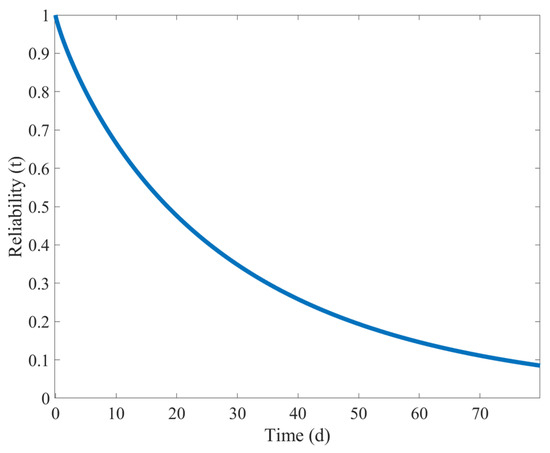
Figure 18.
Reliability curve of sudden impact failure of the shearer spiral drum.
Overall, Figure 18 intuitively shows the changes in the spiral drum’s reliability over time. As the working time increases, the reliability shows a continuous downward trend. When the working time is less than 10 days, the reliability of the shearer’s spiral drum is relatively high. However, within the next 10 days, the reliability of the shearer’s spiral drum drops sharply, indicating that when it cuts through gangue, it will cause significant damage and severely reduce reliability. But the reliability value is still above 0.5. When the working time is 20–50 days, the decline in the reliability of the shearer’s spiral drum is relatively gentle, but the reliability value is below 0.3, indicating that, after sudden loading, the spiral drum may already be in need of repair or replacement. After 50 days, the reliability of the shearer’s spiral drum is already lower than 0.1.
5.2. Reliability Analysis of Natural Wear Failure of the Spiral Drum
Establish Formulas (24)–(27) in MATLAB R2022a software. Substitute the fatigue damage values of the shearer’s spiral drum under natural wear obtained from the simulation into these formulas. Then, the maximum-likelihood estimation solutions for the shape parameter and location parameter of the Gamma process can be obtained. Here, = 2.8558 and = 0.2821. Substitute these values into Formula (12), and the reliability curve of the natural wear failure of the shearer’s spiral drum, as shown in Figure 19, can be obtained.
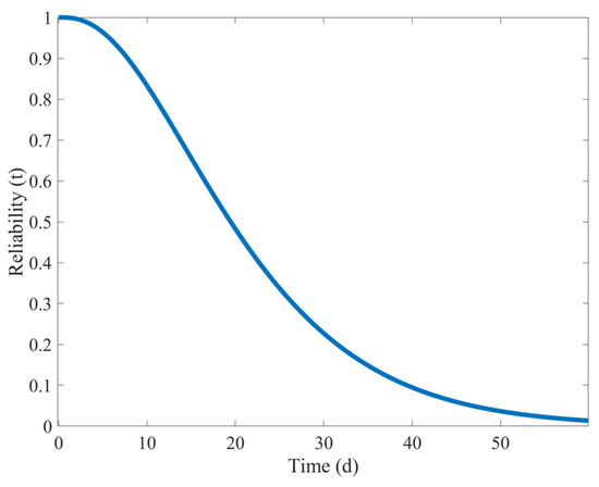
Figure 19.
Natural wear failure reliability curve of the shearer spiral drum.
From Figure 19, it can be seen that under the natural wear condition of the shearer’s spiral drum, the overall downward trend in its reliability is relatively gentle, indicating a steady decline. In the initial stage of the use of the shearer’s spiral drum, the reliability approaches 1, indicating that at the initial moment, the performance of the cutting teeth is in the best state, and the cutting task of the shearer’s spiral drum can be efficiently completed. As time goes by, starting from the 15th day, the downward trend of the reliability of the shearer’s spiral drum becomes more significant. This shows that, after a period of use, the cumulative effect of natural wear on the cutting teeth begins to emerge, significantly affecting their performance and reliability. In the latter part of the curve, the reliability level is already lower than 0.1, indicating that the natural wear of the cutting teeth is very severe, and they may face the risk of failure at any time. If the severely worn cutting teeth are still used, it will not only affect the shearer’s working efficiency but may also lead to equipment damage and production interruptions.
5.3. Analysis of the Competing Reliability of the Spiral Drum
- (1)
- Under the condition that the failure modes are independent of each other, according to Formula (16), the competing reliability curve of the shearer’s spiral drum when the two failure modes are independent can be obtained as shown in Figure 20.
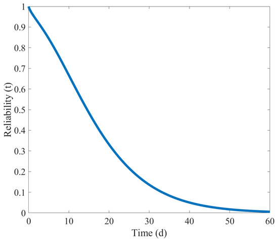 Figure 20. Competitive reliability curve when two failure modes are independent of each other.
As shown in Figure 20, when the shearer’s spiral drum begins to operate and the natural wear state and sudden failure state occur simultaneously, its reliability drops rapidly. Eventually, in less than 30 days, the reliability of the shearer’s spiral drum drops below 0.1.
- (2)
- Under the condition that the failure modes compete with each other, according to Formula (19), the competing reliability curve of the shearer’s spiral drum when the two failure modes are related can be obtained as shown in Figure 21.
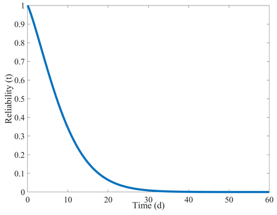 Figure 21. Competitive reliability curve when the two failure modes are related.
As shown in Figure 21, the decline in the reliability of the shearer’s spiral drum becomes steeper. The reliability of the shearer’s spiral drum drops below 0.1 within less than 20 days.
As shown in Figure 22, when natural wear failure and sudden impact failure act together, the downward trend in the reliability of the shearer’s spiral drum is more pronounced than when the two failure modes act alone. Also, the service time decreases from more than 30 days to less than 30 days. Meanwhile, by comparing the reliability curves of the two failure modes when they are independent and when they are related, it can be found that due to the correlation between the two failure modes, the reliability of the shearer’s spiral drum drops sharply in response to a sudden impact when natural wear failure occurs, and the reliability drops below 0.1 after 20 days of operation.
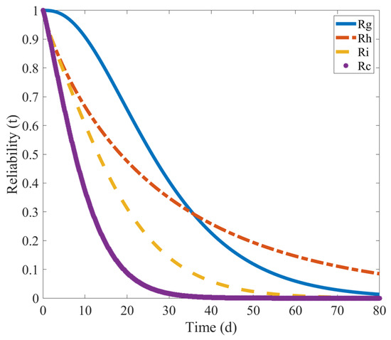
Figure 22.
Reliability curve collection.
By comparing the replacement and maintenance of the cutting teeth of the shearer’s spiral drum in actual engineering operations, it is found that they are consistent with the competitive failure modes, with a correlation between the sudden failure state and the natural wear failure state of the shearer’s spiral drum.
A sudden-failure model of the shearer’s spiral drum was established based on the Weibull distribution, and a natural-wear-failure model of the shearer’s spiral drum was established based on the Gamma distribution. Moreover, competitive reliability models were established for cases in which the two failure modes are independent or correlated. The least-squares and maximum-likelihood methods were used to estimate the model parameters, and reliability curves for four states were obtained. By comparing the reliability curves, under the condition that the two failure modes are correlated, the reliability of the cutting teeth of the thin-seam shearer’s spiral drum is less than 0.1 within less than 20 days, which is consistent with the damage results of the cutting teeth under actual working conditions, verifying the accuracy of the established competitive reliability model.
6. Discussion
This study introduces an integrated approach combining intelligent sensing and competing failure modeling for reliability assessment of spiral drums in thin-seam shearers. The main contribution lies in establishing a competing reliability model that clarifies the interaction between natural wear and sudden impact, using Gamma and Weibull distributions, respectively.
The reliability curve under correlated failures shows a rapid decline to below 0.1 within 20 days, aligning with field observations of a short component lifespan. This observed reliability trend aligns with field reports regarding the short component lifespan in thin seams. More importantly, our model reveals the underlying mechanism: pre-existing wear from natural abrasion reduces the drum’s resistance to subsequent shocks, accelerating failure. This coupled degradation analysis advances beyond traditional independent-failure models, offering a more realistic reliability assessment for components under multi-mode deterioration.
However, the model relies on simplified assumptions such as linear cumulative damage and homogeneous material properties. It does not account for thermomechanical coupling or extreme conditions causing instantaneous fracture, which may affect prediction accuracy under certain scenarios.
Despite these limitations, the proposed method offers a quantitative tool for maintenance planning and provides an applicable framework for reliability analysis of similar complex mechanical systems.
This study enables the development of a reliability prediction module that calculates the spiral drum’s residual reliability in real time using the proposed competing reliability model, automatically triggering maintenance alerts when thresholds are breached. A three-tier maintenance strategy with condition-based intervals is established.
Compared to traditional fixed-interval maintenance, this approach significantly enhances precision—transitioning from arbitrary 30-day cycles to actual condition-based scheduling—potentially reducing unplanned downtime by ~25%. Furthermore, early detection of natural wear trends enables proactive scheduling before impact damage occurs, preventing cascading failures and potentially lowering maintenance costs by 15–20%. These solutions can be integrated directly into existing management systems, providing a concrete technical pathway for intelligent maintenance of thin-seam shearer drums, providing substantial economic and safety benefits for mining operations.
7. Conclusions
To address the problem of analyzing the reliability of the key components of thin-seam shearers, an in-depth reliability analysis of the shearer’s spiral drum is carried out. The following conclusions are drawn:
- (1)
- Numerically simulate the load of the shearer’s spiral drum in MATLAB R2022a software. Successfully obtain the load of the spiral drum and then calculate the values of three-dimensional moments and three-dimensional forces corresponding to each cutting tooth.
- (2)
- Static structural analysis revealed that the maximum equivalent stress occurs at the junction between the cutting tooth and the cutting line. Under natural wear conditions, the maximum stress exceeded 300 MPa, while under sudden impact conditions, it exceeded 600 MPa. Fatigue simulation further showed that the maximum cumulative fatigue damage under natural wear was 2.428 × 10⁻⁷, and under sudden impact, it reached 8.972 × 10⁻⁶. The location of maximum fatigue damage consistently aligned with the intersection of the cutting tooth and the cutting line, consistent with real-world failure patterns.
- (3)
- Four reliability models were constructed. Through comparison, it is verified that there is a correlation between the natural wear failure mode and the sudden impact failure mode of the shearer’s spiral drum. Under the combined action of the two failure modes, the reliability of the cutting teeth of the thin-seam shearer’s spiral drum is less than 0.1 within less than 20 days, which is in line with the wear condition of the cutting teeth under actual working conditions. The competitive reliability model of the shearer’s spiral drum established in this paper provides a theoretical basis and data support for its design and research.
Author Contributions
Conceptualization, M.L. and X.W.; formal analysis, M.L., D.W. and L.Z.; funding acquisition, M.L.; investigation, M.L. All authors have read and agreed to the published version of the manuscript.
Funding
This work was supported by the National Natural Science Foundation of China (Grant No. 51674134), the fundamental research funds for the universities of Liaoning province (Grant No. LJKQZ20222448), and the fundamental research funds for the universities of Liaoning province (Grant No. LJ212410144076, LJ232410144074).
Data Availability Statement
The raw data supporting the conclusions of this article will be made available by the authors on request.
Acknowledgments
We have ensured that all individuals listed in this section have agreed to this acknowledgment; we thank the editors and the anonymous reviewers for their valuable comments and suggestions.
Conflicts of Interest
Author Minghao Li and Dongsheng Wu were employed by Science and Technology Development Corporation, Shenyang Ligong University, Shenyang 110159, China. The remaining authors declare that the research was conducted in the absence of any commercial or financial relationships that could be construed as a potential conflict of interest.
References
- Lin, F. Analysis and Improvement of the Wear Causes of the Spline Root of the Planetary Carrier in the Cutting Unit of the Shearer. Mech. Manag. Dev. 2025, 40, 195–196+199. [Google Scholar] [CrossRef]
- Sun, H. Research on the Technology for Improving the Mining Efficiency of Thin-Seam Working Faces. Coal Mine Mach. 2025, 46, 104–107. [Google Scholar]
- Zhou, Q. Dynamic Simulation of the Gear Transmission System in the Shearer’s Rocker Arm. Mech. Manag. Dev. 2023, 38, 22–24. [Google Scholar]
- Tian, Z.; Jing, S.; Zhao, L.; Gao, S.; Zhang, C. Reliability Prediction of Shearers Based on Particle Swarm Optimization-BP Neural Network. J. Henan Polytech. Univ. (Nat. Sci. Ed.) 2020, 39, 68–74. [Google Scholar]
- Hu, D.; Chi, H.; Lang, R.; Wang, Z.; Sun, P. Analysis of the Control Stability of the Rapid Rotation of the Shearer’s Spiral Drum. Energy Environ. Prot. 2022, 44, 215–219+224. [Google Scholar] [CrossRef]
- Zhang, M.; Zhao, L.; Li, M.; Tian, Z. Analysis of the Vibration Characteristics of the Shearer’s Spiral Drum Based on the Two-Way Coupling Method. Coal Sci. Technol. 2024, 52, 200–216. [Google Scholar]
- Tiryaki, B. Computer Simulation of Cutting Efficiency and Cutting Vibrations in Drum Shearer Loaders. Earth Sci. 2000, 22, 247–259. [Google Scholar]
- Liu, C.; Liu, Y.; Liu, R.; Bai, Y.; Li, D.; Shen, J. Correlated Load Characteristic Model for Shearer Cutting State and Coal-Rock Identification. J. China Coal Soc. 2022, 47, 527–540. [Google Scholar]
- Li, Y. Intelligent Coal-Rock Identification Based on Wavelet Packet Multi-scale Fuzzy Entropy and Weighted KL Divergence. Ind. Mine Autom. 2023, 49, 92–98. [Google Scholar]
- Tiokhin, L.; Derex, M. Competition for novelty reduces information sampling in a research game-a registered report. R. Soc. Open Sci. 2019, 6, 180934. [Google Scholar] [CrossRef]
- Tiokhin, L.; Yan, M.; Morgan, T.J.H. Competition for priority harms the reliability of science. Nat. Hum. Behav. 2021, 5, 857–867. [Google Scholar] [CrossRef]
- Hammond, J.; Crespo, L.G. A distributionally robust data-driven framework to reliability analysis. Struct. Saf. 2024, 111, 102501. [Google Scholar] [CrossRef]
- Bian, L.; Wang, G.; Duan, F. Reliability analysis for systems subject to mutually dependent degradation and shock processes. Proc. Inst. Mech. Eng. Part O J. Risk Reliab. 2021, 235, 1009–1025. [Google Scholar] [CrossRef]
- Wang, X.; Shen, Q.; Han, K.; Wang, C. Reliability Analysis of Aero-engines Based on Multivariate Degradation Modeling under Competing Failures. J. Northeast. Univ. (Nat. Sci.) 2021, 42, 807–813+820. [Google Scholar]
- Qin, Y.; Zhang, X.; Zeng, J.; Liang, H.; Shi, G. Reliability Analysis of Competing Failures of Cutting Teeth of Mining Machinery under Random Load Impacts. J. China Coal Soc. 2022, 47, 3175–3188. [Google Scholar]
- Lu, H.; Jiang, Y.; Jin, X.; Zhang, Y. Reliability Model of Competing Failures of Gear Wear and Contact Fatigue. J. Vib. Meas. Diagn. 2023, 43, 525–530+621. [Google Scholar]
- Zhang, W.; Li, N.; Chen, M.; He, S. Reliability Evaluation Method of Electric Energy Meters Considering Competing Failures in High-Temperature, Dry and Hot Environments. J. Harbin Univ. Sci. Technol. 2024, 29, 71–81. [Google Scholar]
- Zhang, M.; Zhao, L.; Wang, Y. Coal-Rock Cutting State Identification System Based on CPS Perception and Analysis. J. China Coal Soc. 2021, 46, 4071–4087. [Google Scholar]
- GB/T 23561-2009; Methods for Determining the Physical and Mechanical Properties of Coal and Rock. Standards Press of China: Beijing, China, 2010.
- Zhao, L.; Wang, Y.; Zhang, M.; Jin, X.; Liu, H. Adaptive Cutting Control Strategy of Shearers under Complex Coal-seam Conditions. J. China Coal Soc. 2022, 47, 541–563. [Google Scholar]
- Zhang, D.; Liu, C.; Li, D. Reconstruction Algorithm and Numerical Simulation of Drum Cutting Load under Rayleigh Random Distribution. J. China Coal Soc. 2017, 42, 2164–2172. [Google Scholar]
- Wang, X.; Zhang, X.; Yang, L.; Ma, R. Tool Reliability Analysis for Wear-Degradation Data under Competing Failure Conditions. China Mech. Eng. 2020, 31, 1672–1677+1746. [Google Scholar]
- Su, C.; Zhang, H. Reliability Evaluation Based on Performance Degradation Data and Competing-Failure Analysis. J. Mech. Strength 2011, 33, 196–200. [Google Scholar]
- Huynh, K.T.; Barros, A.; Berenguer, C.; Castro, I. A periodic inspection and replacement policy for systemssubject to competing failure modes due to degradation and traumatic events. Reliab. Syst. Saf. 2011, 96, 497–508. [Google Scholar] [CrossRef]
- Park, D.; Kolivand, M.; Kahraman, A. An approximate method to predict surface wear of hypoid gears using surface interpolation. Mech. Mach. Theory 2014, 71, 64–78. [Google Scholar] [CrossRef]
- Walker, J.; Mohammadpour, M.; Theodossiades, S.; Bewsher, S.; Offner, G.; Bansal, H.; Leighton, M.; Braunstingl, M.; Flesch, H.-G. A multi-physices transient wear model for helical gear pairs. Tribol. Int. 2022, 169, 107463. [Google Scholar] [CrossRef]
- Patil, V.; Chouhan, V.; Pandya, Y. Geometrical complexity and crack trajectory based fatigue life prediction for a spur gear having tooth root crack. Eng. Fail. Anal. 2019, 105, 444–465. [Google Scholar] [CrossRef]
- Jafary, B.; Mele, A.; Fiondella, L. Component-based system reliability subject to positive and negative correlation. Reliab. Eng. Syst. Saf. 2020, 202, 107058. [Google Scholar] [CrossRef]


Disclaimer/Publisher’s Note: The statements, opinions and data contained in all publications are solely those of the individual author(s) and contributor(s) and not of MDPI and/or the editor(s). MDPI and/or the editor(s) disclaim responsibility for any injury to people or property resulting from any ideas, methods, instructions or products referred to in the content. |
© 2025 by the authors. Licensee MDPI, Basel, Switzerland. This article is an open access article distributed under the terms and conditions of the Creative Commons Attribution (CC BY) license (https://creativecommons.org/licenses/by/4.0/).