1. Introduction
In recent years, the relentless progress in industrial automation and allied technologies has enabled robotic manipulators to assume numerous complex and repetitive tasks traditionally performed by humans, leading to their widespread adoption in contemporary industrial manufacturing [
1]. Their applications span a diverse range of fields, including assembly processes [
2], medical needle insertion [
3], military operations [
4], precision target grasping [
5], and construction projects [
6], among others. However, this expanded utilization places stringent demands on the control capabilities of these robotic systems. These manipulators exhibit intricate, highly nonlinear, and interconnected second-order dynamic characteristics, which are further exacerbated by uncertainties and external disturbances [
7]. Additionally, factors such as electrical short circuits, harsh environmental conditions, control signal interference, and electromagnetic fields can easily trigger actuator malfunctions, ultimately causing control system failures. Consequently, addressing these challenges to ensure reliable and stable trajectory tracking in robotic manipulators remains a critical focus of current research endeavors [
8].
Currently, a multitude of control strategies have been proposed for the regulation of robotic manipulators, encompassing robust control approaches [
9], optimal control methodologies [
10], adaptive control frameworks [
11], intelligent control systems [
12], and sliding mode control (SMC) techniques [
13]. Despite the successful development and practical implementation of various nonlinear controllers, the quest for designing robust and efficient controllers continues to be a focal point of research. The SMC strategy is particularly favored in the controller design of robotic systems owing to its merits of swift response, superior transient performance, straightforward implementation, and resilience against external disturbances and model uncertainties [
14]. Presently, linear sliding mode (LSM), terminal sliding mode (TSM), fast terminal sliding mode (FTSM), and other allied technologies have been harnessed to address the motion control challenges inherent in robotic manipulators [
15,
16,
17,
18,
19,
20].
As an effective means to attenuate chattering, the STA is frequently incorporated into SMC strategies [
21]. The principal drawback of STA lies in its requirement for precise knowledge of the disturbance gradient’s upper bound; however, a notable limitation of SMC is the challenge in accurately determining this bound in practical applications. Overestimating this bound results in excessively high control gains, which may degrade system performance [
22]. Presently, numerous studies have adopted the barrier function as the gain for STA. In [
23], a novel variable-gain STA based on the barrier function is introduced, which effectively mitigates control input overestimation and reduces chattering in the control signal. Nevertheless, abrupt changes in the sliding variable can induce an escape phenomenon, particularly when a robotic manipulator executes sudden tasks. This issue becomes especially pronounced during actuator failures, where effective suppression of interference during the switching process is unattainable [
24,
25,
26].
The performance of manipulators is inherently limited by their mechanical characteristics, rendering them vulnerable to performance degradation caused by unfavorable external factors such as voltage fluctuations and excessive loads. A key outcome of this susceptibility is a reduction in tracking accuracy [
27]. Consequently, the challenge of sustaining precise tracking control for manipulators, particularly in fault conditions, has emerged as a critical research area focused on improving control performance under non-ideal circumstances. Within this domain, fault-tolerant control (FTC) methodologies are extensively employed and generally categorized into active and passive approaches [
28]. The active strategy functions by employing a fault diagnosis observer to detect and acquire information regarding system faults, which is subsequently utilized to implement corrective compensations. Although this method proves highly effective in enhancing control performance, its execution inevitably results in elevated computational complexity and increased costs [
29]. In [
30], a robust fault-tolerant SMC approach is proposed to ensure global fixed-time stability for robotic manipulators. This method integrates a fixed-time second-order sliding mode observer with a fixed-time SMC design strategy, thereby guaranteeing system robustness while achieving superior tracking performance. Conversely, the passive strategy leverages the inherent resilience of robust controllers. These controllers are designed to sustain satisfactory performance under both normal and faulty operating conditions without relying on explicit fault information. The intrinsic simplicity of this architecture enables a more rapid compensatory response when faults occur [
31]. In [
32], a fixed-time fault-tolerant control scheme incorporating a sliding mode observer is introduced, which substantially enhances system stability and robustness against disturbances. The distinctive feature of this strategy lies in its combination of passive fault-tolerant control, SMC, and a sliding mode observer, ensuring that the system state converges to a minimal neighborhood near the equilibrium point within a fixed time, regardless of whether the system is in normal or faulty operation. However, these methods rely heavily on fixed-time observer structures, which increase the computational burden and require precise fault modeling. Their switching control laws may also induce chattering due to discontinuous terms. In contrast, the proposed
-based adaptive super-twisting design eliminates the need for explicit fault estimation, ensures smooth control action, and achieves finite-time convergence with reduced chattering and computational complexity.
Inspired by the above references, we propose a novel
function-based adaptive P-FTSMC strategy, which aims to address the challenge of trajectory tracking for robotic manipulators. The newly designed P-FTSM surface effectively mitigates chattering while enhancing convergence speed. Additionally, the
function is selected as the control gain, which not only reduces the computational complexity but also prevents barrier function escape in scenarios characterized by abrupt changes in sliding variables. Furthermore, its strong robustness can effectively mitigate the adverse effects caused by actuator failures. By utilizing this
function, the controller prevents gain overestimation, thereby further mitigating chattering.
Table 1 is a summary of the comparison and analysis of the aforementioned literature, as well as a summary of the advantages of the proposed method. The main contributions of this article are as follows:
A new sliding surface, named P-FTSM, is designed to further improve the convergence rate while weakening the chattering.
The proposed function addresses the discontinuity of the control input caused by the switch of the barrier function, avoids the destabilization of the system when the sliding variable is undergoes abrupt changes and does not require the determination of the switch time by trial and error.
In the proposed STA based on the function, the high-frequency switching is placed after the integration operator, ensuring that the control gain is continuous and the control input is smooth, which is beneficial for practical applications.
The function-based STA does not require the assumption of the upper bound of the external disturbance and does not need to use a low-pass filter.
The rest of the paper is structured as follows:
Section 2 describes the dynamic model of the robotic manipulators and some preparations. A
function STA adaptive P-FTSM controller is designed for the robot manipulators, and a finite-time stability proof is presented in
Section 3. A set of comparisons with LSM, TSM and FTSM controllers is presented in
Section 4, along with comparison experiments with reference [
12].
Section 5 presents some conclusions of this paper and future work.
3. Adaptive P-FTSM Controller Design
To begin, we define the tracking error for the manipulator system (
8) with respect to a desired trajectory
:
The P-FTSM surface is designed to ensure rapid error convergence as follows:
where we select
as positive constant vectors and choose the elements of
to be between 0 and 1.
We construct the overall control law
from two components: an equivalent part
and a switching part
. To derive the equivalent control
, we first differentiate the sliding surface (
11) with respect to time:
By solving for the control input under the ideal condition
, one has
Next, we design the switching controller
to drive the system states to the sliding surface, for which we use
functions:
This controller incorporates an auxiliary state variable
v, for which we define the dynamics as
According to Definition 1, we structure the terms
and
as the following
functions:
with
being positive constant vectors that we can tune.
In implementation, the adaptive gains are restricted to a compact design set
and
, which can be guaranteed by gain clipping without altering the form of (
16).
Finally, we obtain the total control effort by summing these two components:
Here, we use the expressions from (
13) and (
14) for
and
respectively, and we set the initial condition for the auxiliary state to
. And the flow chart of the proposed controller is shown in
Figure 1.
Theorem 1. For the robotic manipulator system described in (8), the application of the control law (17) with the P-FTSM surface (11) guarantees that the tracking error will converge to zero in finite time. Consequently, the manipulator will accurately follow the desired trajectory. Proof. To begin the analysis, let us define an auxiliary vector
as
. The dynamics of this vector can be expressed by its time derivative:
where
and the matrix
is defined as
We introduce the Lyapunov function candidate to assess stability:
where
P is a symmetric positive definite matrix selected as
With this choice, P is positive definite and ensures that the Lyapunov equation admits a positive definite solution.
The time derivative of
along the system trajectories (
18) yields
where the matrix
is defined as
Since
, it follows that
. According to the Schur complement condition,
is positive definite if
. Because
Q depends affinely on the adaptive gains
defined in (
16), we restrict them to a compact design set
which can be guaranteed by gain clipping without altering the structure of (
16). By appropriately selecting
P, there exists a constant
such that
In practice,
and
vary continuously with
s, so
is time-varying. Let
be the nominal constant matrix and define the bounded perturbation
with
Let
, which is positive definite. Then (
22) can be rewritten as
Using the inequality
and applying (
26)–(
27), we obtain
If the following design margin condition is satisfied,
then we have
The inequality in (
31) has the same form as in the standard super-twisting analysis, which implies that
converges to the origin in finite time. Consequently, the sliding variable
s and the tracking error both converge to zero in finite time. An upper bound for the convergence time
, starting from an initial time
, is given by
where the constant
is defined as
This completes the proof. □
Remark 1. The P-FTSM surface (11) integrates the advantages of terminal sliding mode and fast convergence characteristics. The hyperbolic tangent function ensures smoothness and continuity of the sliding surface, which helps reduce chattering. The function-based switching gains and are adaptive to the sliding variable magnitude, preventing overestimation of control gains while maintaining robust performance against uncertainties, disturbances, and actuator faults. 4. Saturated Adaptive P-FTSM Controller Design
The adaptive P-FTSM controller proposed in the previous section guarantees finite-time convergence and exhibits robustness against uncertainties and faults. However, when the initial tracking error is large, the functions and can generate significant gain values, potentially leading to an initial control input that exceeds the physical limitations of the robotic manipulator’s actuators. This issue, known as input saturation, is a critical consideration in practical implementations.
To address this problem and ensure the controller’s feasibility, we introduce a modified control scheme based on a saturation function, which prevents the control magnitude from becoming unacceptably large while ensuring system stability and convergence.
Let the non-saturated switching control term be defined as
. We now introduce a saturation function to constrain this term within a prescribed bound. The saturated switching controller
is designed as follows:
where
is a vector of prescribed positive constants representing the maximum allowable magnitude for the switching control component for each joint. The saturation function is defined element-wise for a vector input
x and bound
as:
The complete saturated control law is thus given by
where
is the equivalent controller from (
13), and the auxiliary state
v within
is still integrated according to (
15).
To ensure the effectiveness of this saturated controller, the following assumption is necessary:
Assumption 1. It is assumed that the maximum control capability can suppress the lumped disturbances, i.e., the saturation bound is chosen to be sufficiently large such that , where is the upper norm-bound of the lumped disturbance δ defined in (8). Theorem 2. Consider the robotic manipulator system (8) with the P-FTSM surface (11). If Assumption 1 holds, the saturated adaptive controller (36) guarantees that the system trajectories reach the sliding surface within a finite time. Proof. The stability proof is divided into two parts, analyzing the system behavior when the controller is saturated and when it is not. Let us define the unsaturated region as .
(1) Saturated Phase: In this phase, at least one component of the switching control is saturated. We select the candidate Lyapunov function:
Taking the time derivative of
along the system trajectories yields
Substituting
and the system dynamics (
8), we know that
, where
represents all known dynamics and
is the lumped uncertainty. The expression for
can be simplified to
where
is the new lumped disturbance term incorporating system dynamics, external disturbances, and faults. Under Assumption 1, this term is bounded, i.e.,
.
Substituting (
39) into the derivative of
gives
In the saturated phase,
is equal to
in magnitude, and its direction opposes the sliding variable
s. Thus,
. Therefore,
According to Assumption 1, the term
is a positive constant,
, and one has
Based on the finite-time stability theory, this inequality ensures that the system trajectory will reach the boundary of the unsaturated region in a finite time .
(2) Unsaturated Phase: Once the system trajectory enters the region
, the controller is no longer saturated, i.e.,
. The control law (
36) becomes identical to the non-saturated controller (
17).
At this point, the controller reduces to (
17). According to the revised Theorem 1, using the same Lyapunov function
with the symmetric
in (
21) and the design margin
in (
30), the finite-time convergence conclusion still holds for the unsaturated phase within finite time
.
Since the trajectory is driven into the region in finite time , and subsequently converges from within to the sliding surface within convergence time , the overall stability within finite time is guaranteed. The total settling time satisfies . □
Remark 2. The introduction of the saturation function effectively protects the actuators from demanding excessive torque, thereby enhancing the practical applicability of the proposed controller. While ensuring stability, this modification may result in a slightly longer convergence time compared to the ideal non-saturated case, as the control effort is capped during the initial reaching phase. This represents a well-understood trade-off between performance and the protection of physical hardware.
5. Simulation Results
The effectiveness of the proposed control approach is demonstrated via numerical simulations on a two-link robotic manipulator, conducted using MATLAB/SIMULINK version 2024b. For Equation (
8), the dynamic model components are specified as follows:
where the joint angle can be described as
, with
,
,
,
,
, and
.
and
denote the masses of symmetric manipulator links,
and
are their respective lengths, and
g stands for the acceleration of gravity, with the parameter values listed in
Table 2.
5.1. Comparative Simulations
In the simulation, the initial states of the manipulator are set as
and
. Furthermore, it is necessary to track the desired signal
with
and
. The control parameters can be chosen as follows:
,
,
, and
. For the
functions in Equation (
16),
adopts
, while
uses
. The switching control input is limited by
.
To assess the performance of the proposed controller, comparative simulations are conducted against the approaches described in [
30,
32]. In these simulations, the manipulator is exposed to external disturbances as well as an actuator fault, which is introduced at
t = 5 s and specified as follows:
The disturbance applied to the system is given by with .
For comparison, the method referenced is from [
32], where the sliding manifold and corresponding control law are constructed as follows:
and
where
and
represents the STA, with
, and
.
For the second comparison, the sliding manifold and controller from [
30] are formulated as follows:
and
The controller parameters are selected to meet the following requirements:
,
,
,
, and
. The value of
is set as
, where
. For the comparative simulations, the parameters of the controller (
47) and (
49) are chosen in accordance with those in the original references [
30,
32].
Remark 3. The control parameters were selected through a trial-and-error process to balance convergence speed and chattering suppression. All parameter values were tuned empirically within stable ranges to ensure smooth control performance and finite-time convergence.
Table 3 provides a quantitative comparison of convergence performance. The proposed controller achieves the shortest convergence times for both
and
, indicating a faster transient response than Refs. [
30,
32]. It also yields smaller RMSE and IAE values, confirming higher tracking accuracy. While the control effort remains comparable across all methods, the proposed scheme shows a markedly lower total variation
, implying smoother control inputs and reduced chattering.
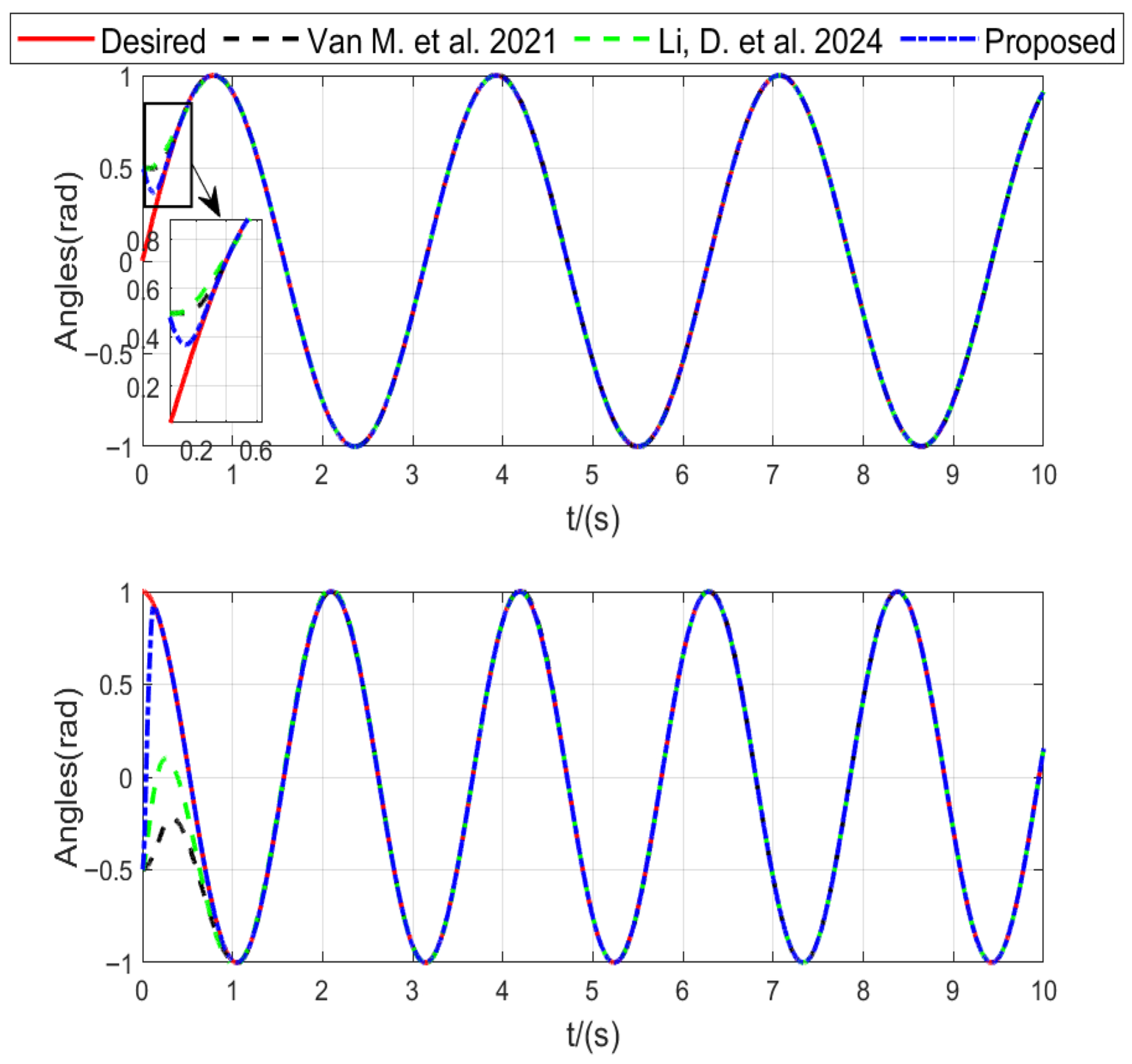
As illustrated in
Figure 2, the tracking results visually demonstrate that the proposed method enables the manipulator to reach the desired trajectory more quickly.
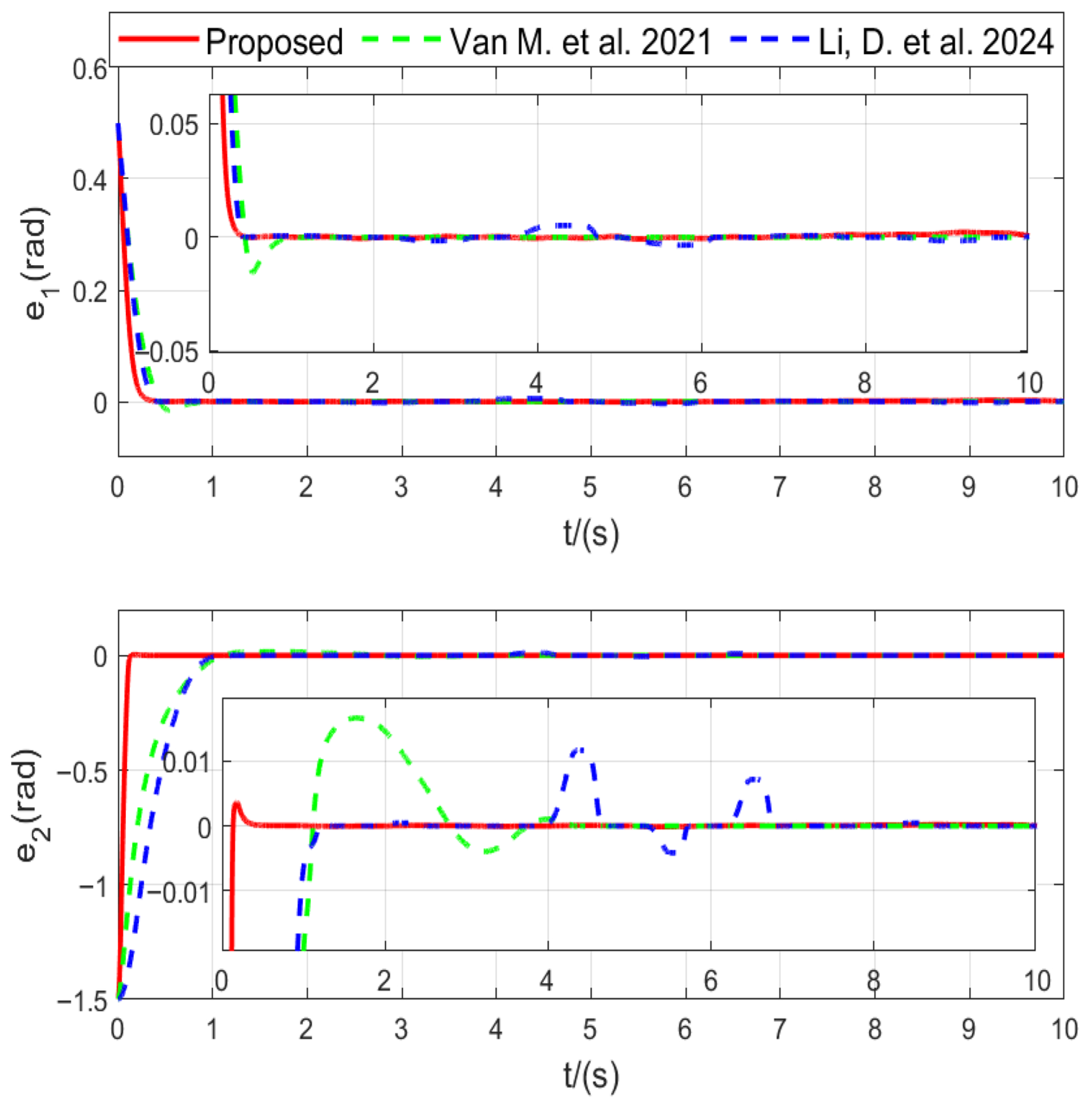
The tracking error results in
Figure 3 show that the scheme in this research leads to a smaller error. Furthermore, the control input curves in
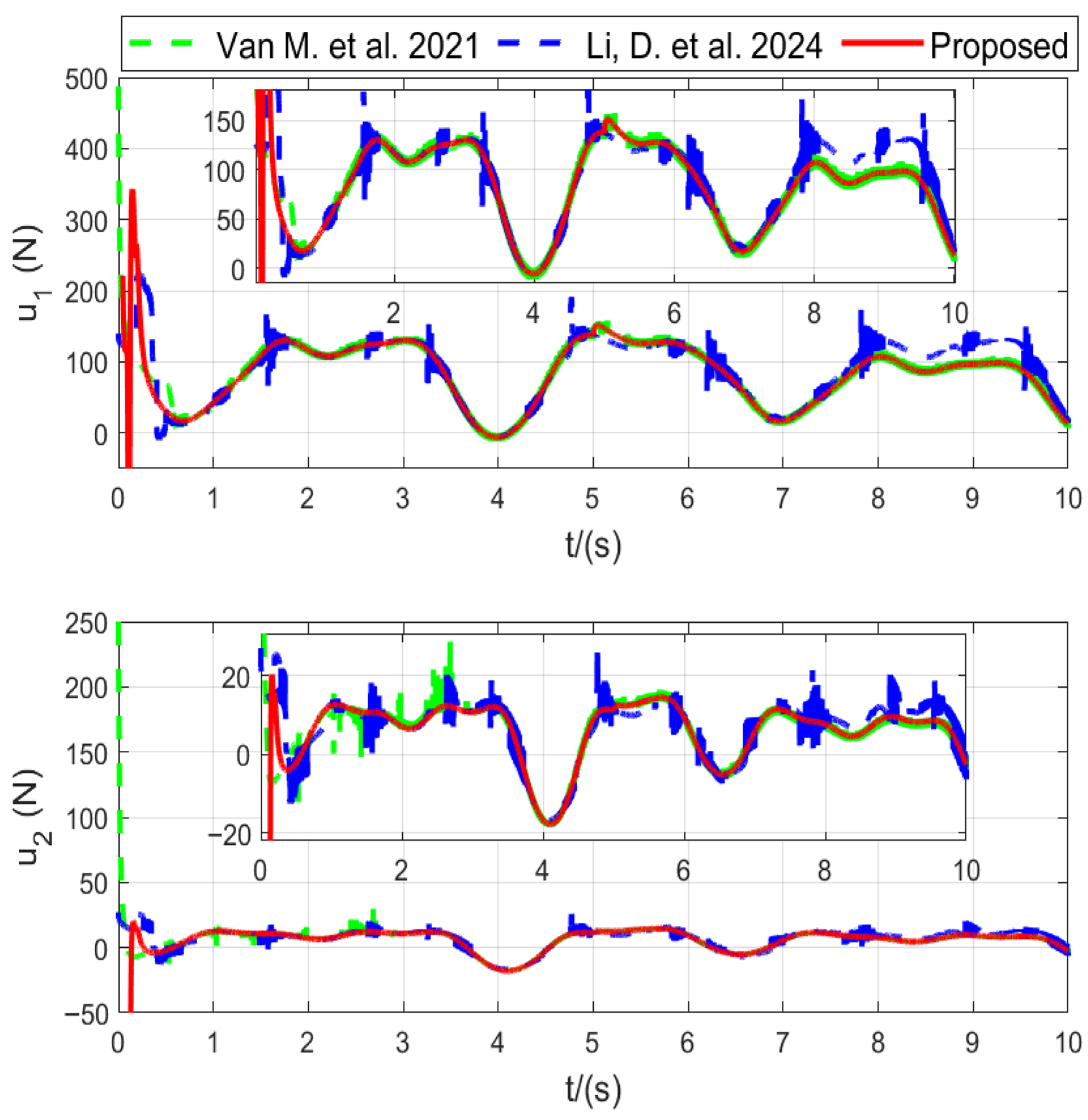
Figure 4 indicate that the proposed approach effectively suppresses chattering.
In
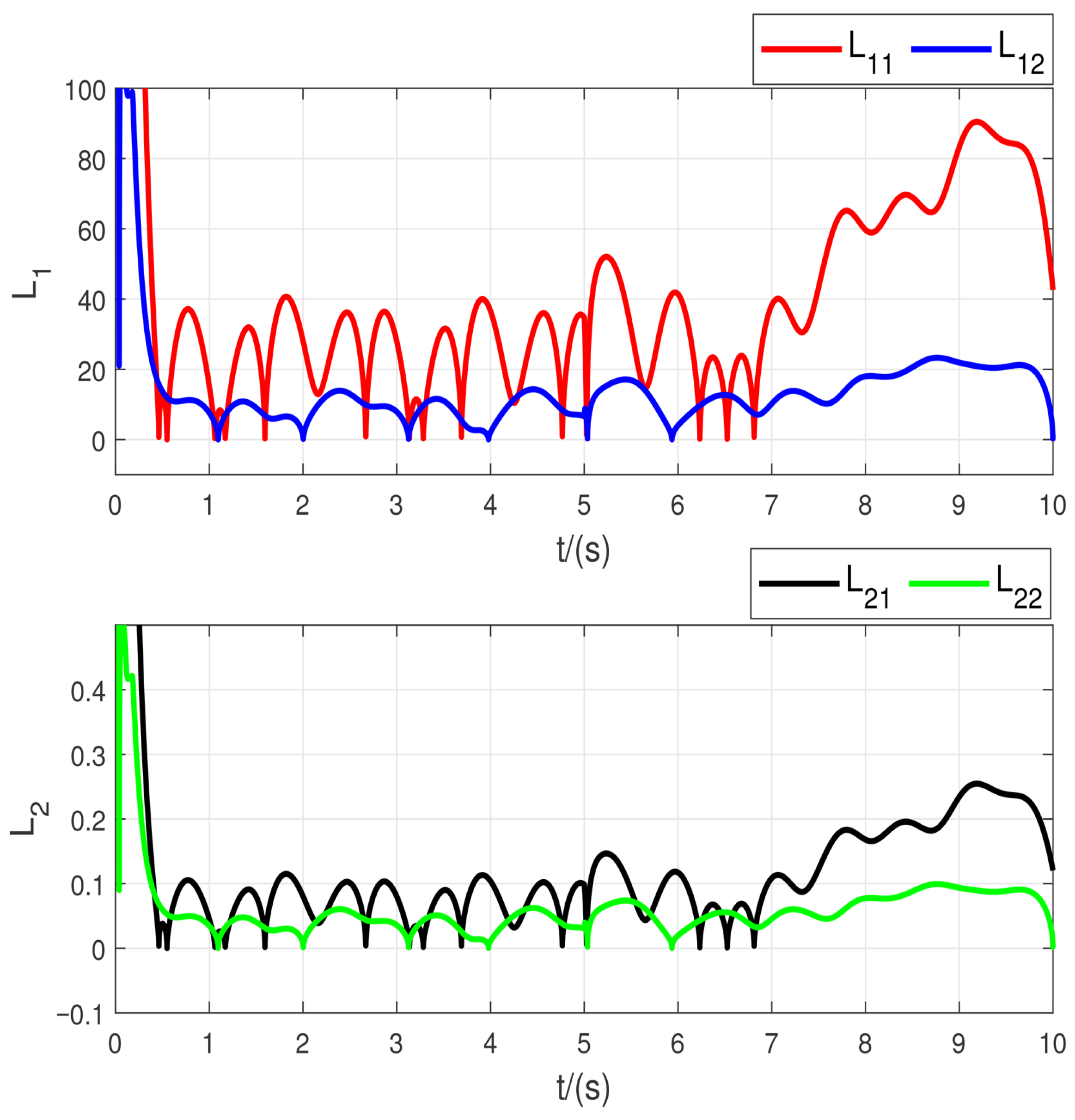
Figure 5, the adaptive gains are plotted, showing that the proposed method effectively adjusts the gains smoothly.
The simulation results clearly demonstrate the effectiveness of the proposed controller. As shown in
Table 3, the proposed method achieves the fastest convergence and the smallest tracking errors among all compared approaches. Both RMSE and IAE values of the joint errors are significantly lower, indicating higher steady-state accuracy and better transient response. The reduction in the total variation of control signals by more than one order of magnitude verifies that the
-based design effectively suppresses chattering while maintaining smooth control actions. Furthermore, the smaller control energy
shows that the adaptive gain mechanism avoids excessive control effort. These results confirm that the proposed adaptive fault-tolerant super-twisting controller provides superior robustness and precision compared with existing methods.
5.2. Additional Test
To further validate the robustness of the proposed controller, two additional test cases are conducted under different fault and disturbance conditions while keeping all controller parameters unchanged.
Case 1. In this case, a simultaneous loss of effectiveness occurs in both actuators at
s, modeled as
The system is also subjected to a time-varying disturbance defined as , with . This test evaluates the controller’s ability to maintain finite-time convergence and smooth tracking performance under simultaneous actuator degradation and periodic disturbance excitation.
Case 2. After the fault time
, the actuator command is affected by a multiplicative Loss-of-effectiveness (LOE) and an additive bias:
where
is the unit step,
encodes the LOE ratios of the two actuators, and
N·m is the constant bias.
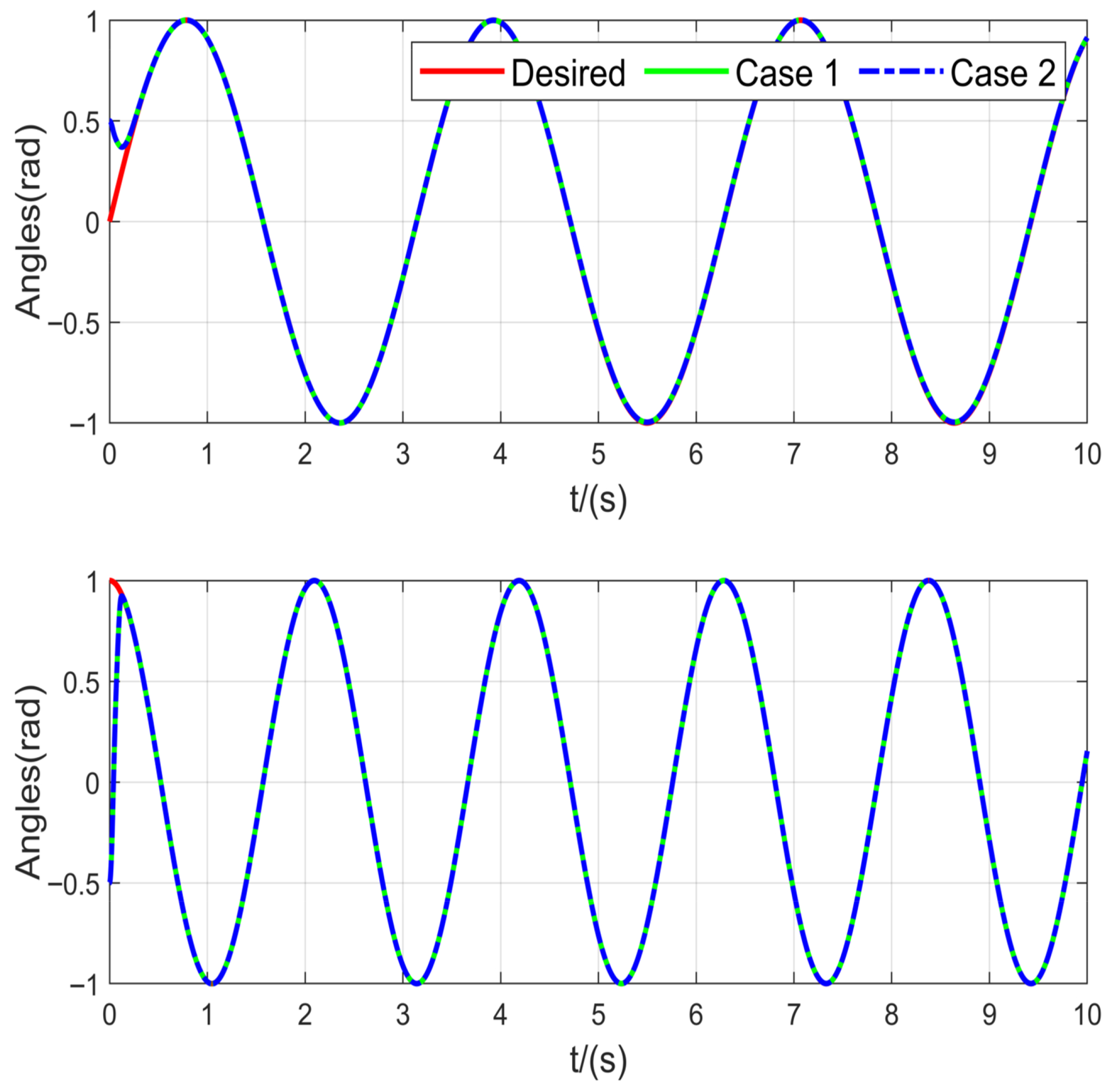
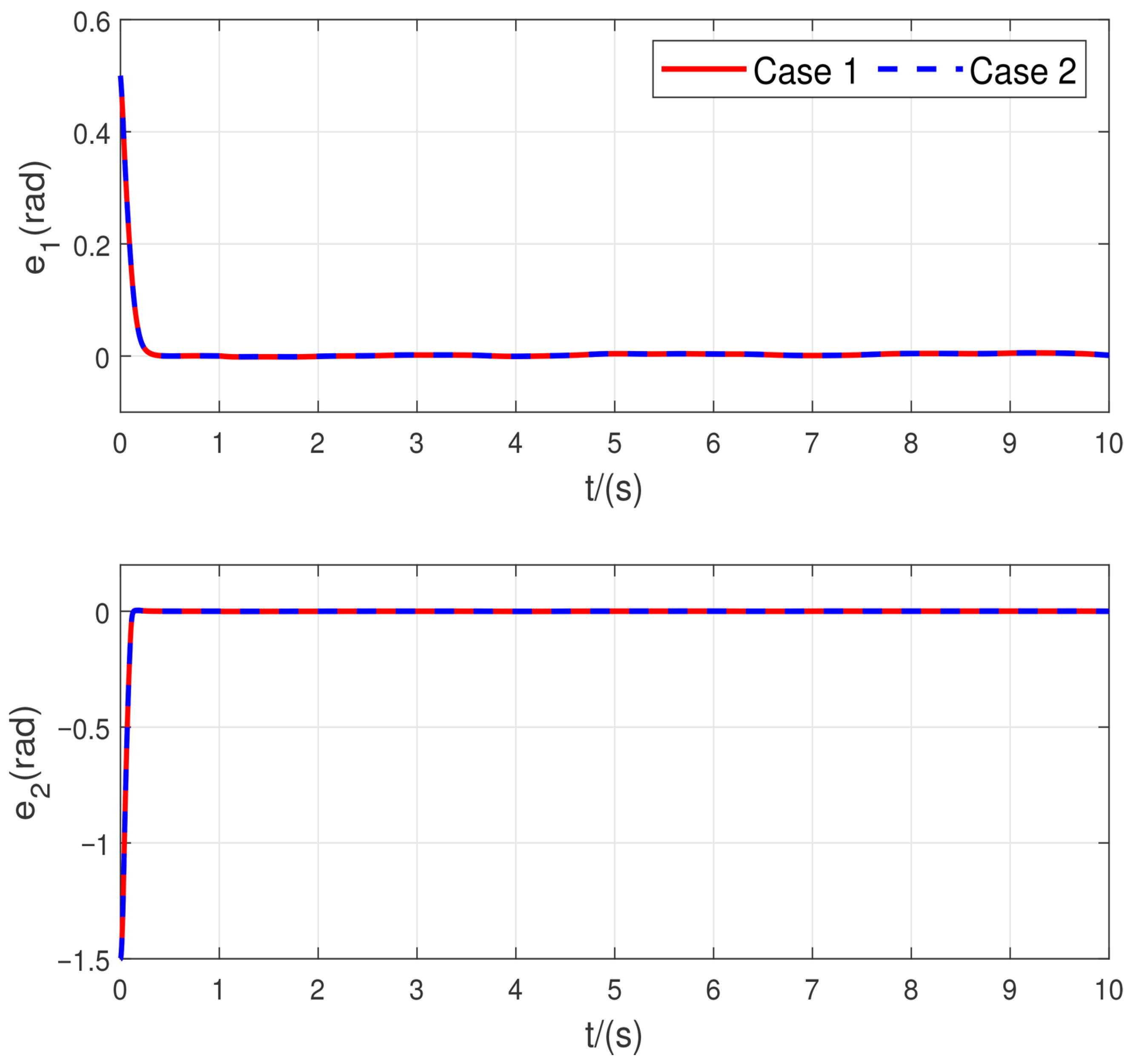
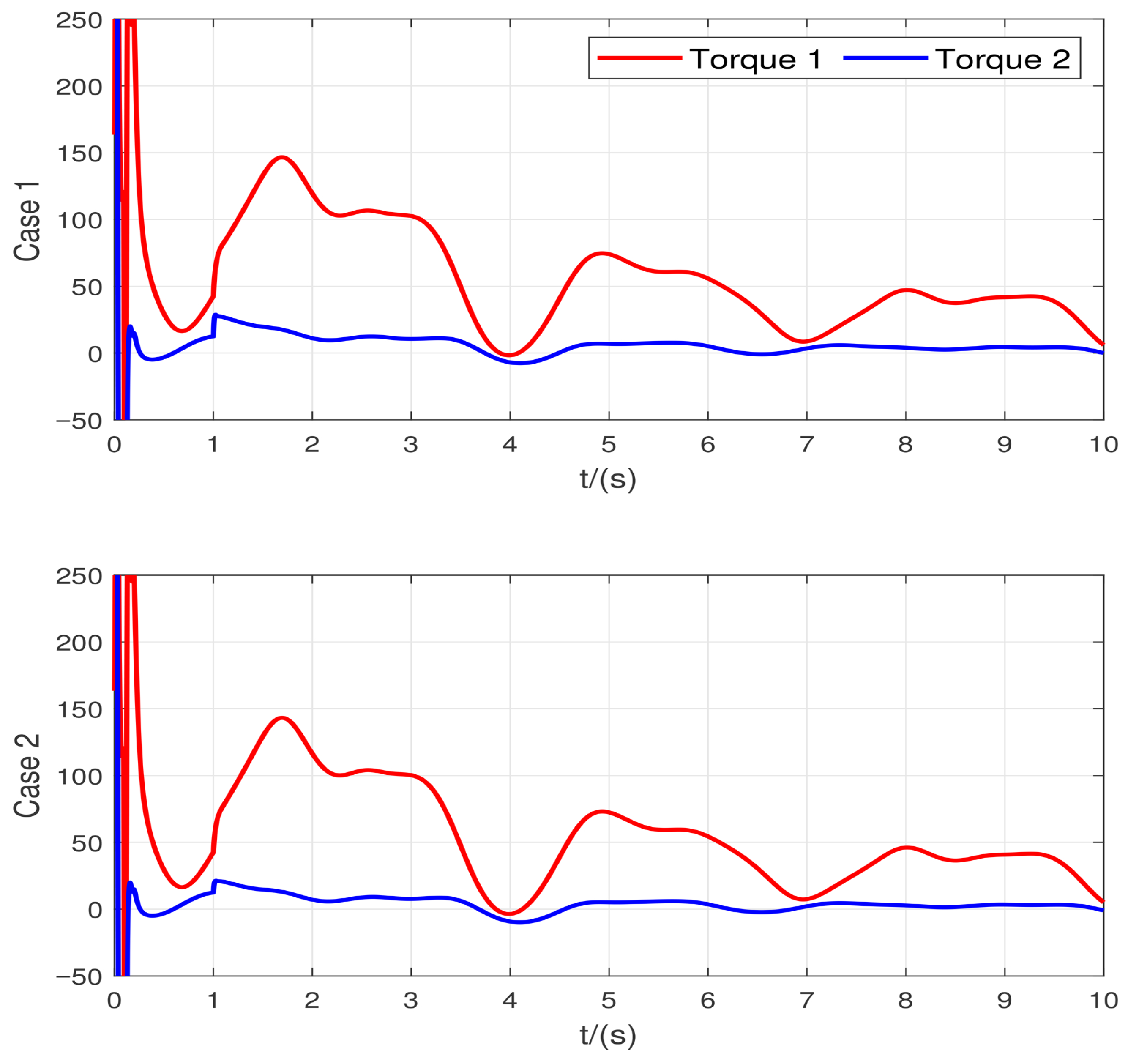
As illustrated in
Figure 6 and
Figure 7, the proposed controller maintains almost identical tracking and control performance, even under broader testing conditions involving different fault types, fault magnitudes, and external disturbances. Furthermore,
Figure 8 shows the control input is smooth and chattering is suppressed, even under the fault and disturbance conditions. The state trajectories remain smooth and converge within the same finite-time bounds, while the control inputs show negligible variation compared with the nominal case. These results clearly demonstrate the strong robustness and fault-tolerant capability of the proposed
-based adaptive super-twisting control scheme.
5.3. Frequency-Domain Analysis
To further evaluate the dynamic characteristics of the proposed controller, a frequency-domain analysis was performed. In this experiment, the input–output data were collected from the manipulator operating under the same simulation conditions as those described in the
Comparative simulations section. The desired trajectories were set as
and
, while the actuator faults and external disturbances were introduced according to Equation (
45), resulting in a
loss of effectiveness in both actuators. The sampling period was fixed at
, identical to the time-domain simulation.
The Bode diagram was obtained from time-domain data by estimating the empirical frequency response function (FRF) using the Welch method, expressed as
where
and
denote the cross- and auto-power spectral densities of the control input
and tracking error
, respectively. The magnitude and phase responses were plotted on logarithmic scales to obtain the conventional Bode representation. The window length
was selected as the largest power of two not exceeding one-eighth of the total data length, with
overlap and FFT size
. The sampling frequency was
, and the frequency axis was limited to the range
to capture the system’s practical bandwidth.
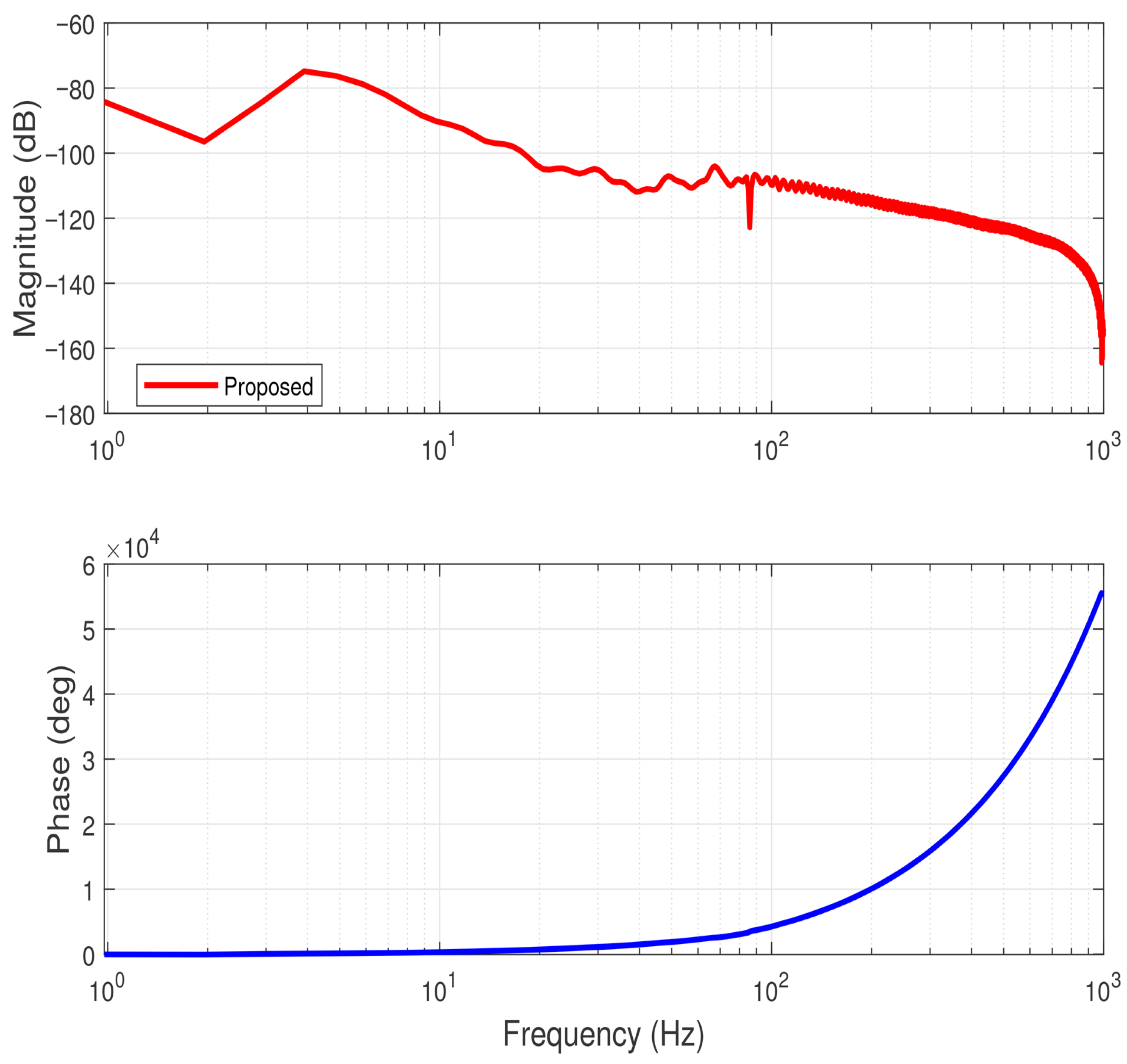
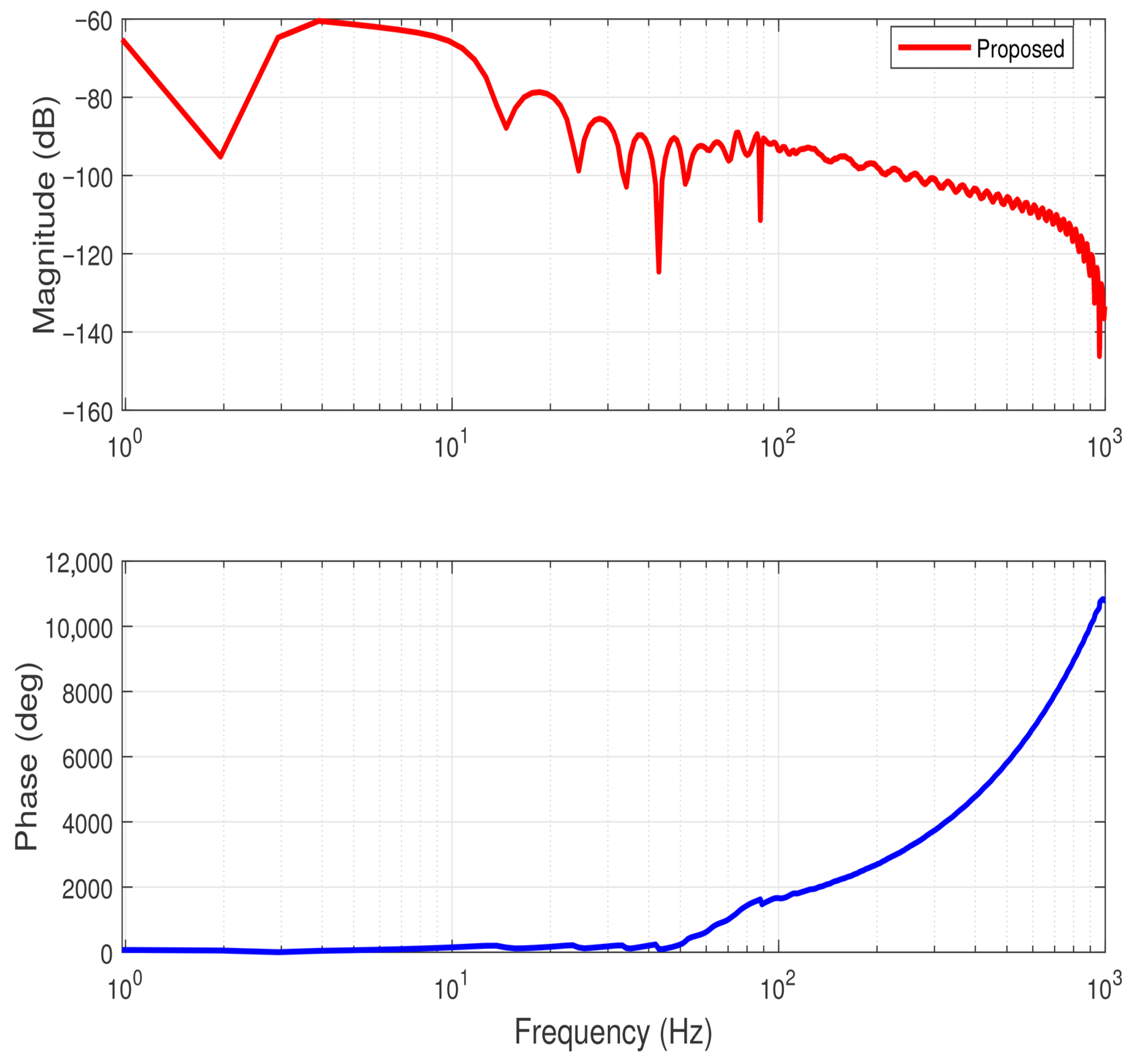
Figure 9 and
Figure 10 illustrate the Bode magnitude and phase plots of the proposed adaptive fault-tolerant controller under actuator loss-of-effectiveness.
As shown in the figure, the magnitude response remains well below across the entire frequency spectrum, demonstrating strong closed-loop stability and excellent attenuation of high-frequency components. In the low-frequency range (1–10 Hz), the magnitude is approximately , indicating highly effective suppression of steady-state error and disturbances. At mid-to-high frequencies (– Hz), the amplitude further decreases, revealing the controller’s strong noise rejection capability even under partial actuator degradation. The smooth, monotonic decay without excessive peaking confirms that the system exhibits no resonance phenomena or instability.
The phase plot shows a continuous and monotonic trend, with gradual phase lag as the frequency increases. This behavior implies a stable, causal, and well-damped dynamic response. Even in the presence of actuator faults, no abrupt phase shifts or discontinuities were observed, which confirms that the proposed K∞-based adaptive super-twisting controller maintains smooth closed-loop dynamics and robustness against non-ideal actuation.
The frequency-domain characteristics demonstrate that the proposed controller ensures a wide stability margin and strong attenuation of high-frequency disturbances. The Bode plots validate that the system retains robust performance under actuator loss-of-effectiveness, with excellent disturbance rejection and smooth phase behavior, further confirming the controller’s reliability and practical applicability in fault-tolerant robotic systems.

