Abstract
The AlCrFeMoTi high-entropy alloy exhibits promising application potential as a corrosion-resistant structural material in advanced nuclear energy systems, particularly in lead–bismuth fast reactors. In this present study, first-principles calculation based on the density functional theory was employed to investigate the phase and electronic structure of AlCrFeMoTi HEA. The Gibbs free energy calculation results and XRD experimental results both indicate that the BCC phase is more stable for AlCrFeMoTi HEA. The atom distribution model was constructed according to the site preference of atoms occupying sublattices. The results indicate that alloying atoms have an obvious site preference. For example, Fe, Mo, and Cr atoms always prefer the 1a sublattice, while Al and Ti atoms tend to favor the 1b sublattice. And the atom site preference is temperature-sensitive. At 973 K, the site occupancy configuration is (Al5Cr16Fe26Mo17Ti0)1a(Al21Cr9Fe0Mo9Ti25)1b. Based on the steady-state phase structure, the band structure, density of states, and charge density were calculated. The electronic structure results show that metal bonds are formed between alloying elements in AlCrFeMoTi HEA, exhibiting strong metallic properties.
1. Introduction
High-entropy alloys (HEAs) are a new type of alloy formed by mixing five or more elements in nearly equal atomic ratios. The mixing of multiple principal components leads to a significant increase in configuration entropy, promoting the formation of simple solid solutions such as body-centered cubic (BCC), face-centered cubic (FCC), or hexagonal close-packed (HCP), rather than complex intermetallic compounds. Under the four major effects of lattice distortion, delayed diffusion, cocktail, and slow coarsening, it has high strength, high hardness, high wear resistance, good high-temperature oxidation resistance and corrosion resistance, and superior thermal stability [,,]. Therefore, it has attracted a lot of attention in fields such as aerospace, nuclear energy, healthcare, and catalysis [,,,,,,].
The lead–bismuth fast reactor is a reactor that uses liquid lead–bismuth eutectic (LBE) alloy as a coolant and has extremely high inherent safety. It is one of the six advanced reactor types identified by the international fourth-generation nuclear energy system. However, the bottleneck problem restricting the development of lead–bismuth fast reactors is the corrosion resistance of core structural materials in high-temperature liquid LBE alloys [,]. Preparing corrosion-resistant coatings on the surface of candidate structural materials is the most cost-effective solution among numerous approaches [,]. At present, the coatings reported to improve the corrosion resistance of structural materials in high-temperature liquid LBE alloy mainly include ceramic coatings (mainly Al2O3 [], TiSiN [], and CrN [,]), metal coatings (mainly Al [] and Cr []), and alloy coatings (mainly Fe-Al alloys [], Fe-Cr-Al alloys [], and HEAs [,,,]). Among them, HEA coatings not only significantly slow down the corrosion of LBE, but also have good creep resistance due to lattice distortion and delayed diffusion effects, and complex components that can hinder dislocation movement and reduce the accumulation of irradiation defects, which have received a lot of attention [,]. Considering the requirements for the use of LBE-cooled fast reactors, Al, Cr, Fe, Mo, and Ti were selected as the primary elements for the coating, for the following reasons: (a) compared to Ni and Mn, Al, Cr, Fe, and Mo have lower solubility in LBE; (b) Al and Cr are strong oxidizing elements that readily form dense oxide films, providing excellent corrosion resistance; (c) the addition of Mo and Al, which have atomic radii larger than those of Fe and Cr (Al ~ 0.143 nm, Cr ~ 0.125 nm, Fe ~ 0.124 nm, Mo ~ 0.136 nm), increases atomic size mismatch, resulting in significant lattice distortion and increased strain energy, which favors the formation of nanocrystalline or amorphous structures; (d) the selection of Fe and Cr improves the metallurgical bonding between the coating and the substrate, thereby enhancing the adhesion between them; (e) Ti offers excellent corrosion resistance and has a low neutron absorption cross-section, which does not significantly reduce the neutron flux in the reactor, thus contributing to the efficient operation of the reactor [,]. Yang et al. successfully deposited an amorphous AlCrFeMoTi high-entropy alloy (HEA) coating with a near-stoichiometric molar ratio on an F/M substrate using magnetron sputtering. Compared to uncoated F/M steel, the coating exhibited excellent corrosion resistance in LBE, with a thinner oxide layer and lower coating consumption. However, when the corrosion temperature reached 650 °C, element segregation and localized oxidation occurred within the coating, and Fe oxide corrosion products and voids appeared at the coating-substrate interface [,].
At present, research on HEA coatings for LBE corrosion mainly uses experimental methods to characterize their structural evolution in high-temperature liquid LBE alloys. The multi-component characteristics of HEAs indeed lead to a significant increase in their structural complexity, which brings both unique performance advantages and challenges in regulating the microstructure [,]. The macroscopic properties exhibited by materials are determined by their microstructure. The corrosion behavior of materials is closely related to their nuclear electronic structure []. The higher the Fermi level of a metal, the more likely it is to lose electrons and undergo oxidation. Regions with low electron density on the metal surface, such as grain boundaries and defects, are prone to becoming anodic dissolution sites. The site preference of different metallic elements in high-entropy alloys (HEAs) plays a decisive role in determining their microstructure, phase stability, and macroscopic properties such as mechanical performance, thermal stability, and corrosion resistance. Clarifying the atomic site occupation tendencies helps to elucidate, at the atomic scale, the mechanisms of phase formation, the origins of lattice distortion, and the evolution of electronic structures. For alloys such as AlCrFeMoTi, which are designed for application in harsh nuclear environments (e.g., lead–bismuth eutectic coolants), understanding atomic-scale ordering is crucial for predicting and optimizing their corrosion and irradiation resistance []. First-principles calculations are an effective and economical tool for predicting material properties based on atomic size. In recent years, it has been widely used to predict the phase stability, mechanical properties, and electronic structure of HEAs [,,,]. Therefore, this study employs first-principles calculations to systematically investigate the site preferences of each element in the AlCrFeMoTi HEA, aiming to provide a theoretical foundation for uncovering the microscopic mechanisms underlying its stable phase structure and associated properties.
In this present study, first-principles calculation was adopted to calculate the steady-state phase and electronic structure of AlCrFeMoTi HEA. Firstly, the BCC and FCC models of AlCrFeMoTi HEA were established based on the general sublattice model proposed by Wu et al. []. According to Gibbs free energy and XRD experimental data, the steady-state phase structure was determined. Next, the atom distribution model was constructed based on the site preference of atoms occupying sublattices, and structural optimization calculations were carried out for AlCrFeMoTi HEA with the BCC phase. By completely relaxing the structure, a stable distorted configuration was developed, and its distortion enhancement mechanism was revealed. Finally, based on the fully relaxed model, the band structure, density of states, and charge density of AlCrFeMoTi HEA were calculated. For the first time, a systematic study was conducted on the phase stability, atomic-scale site preference, lattice distortion mechanisms, and electronic structure of AlCrFeMoTi high-entropy alloys by combining thermodynamic calculations, first-principles electronic structure analysis, and experimental validation (LDED preparation and XRD characterization). This multi-scale, multi-method approach overcomes the limitations of individual calculations or experiments, providing a more comprehensive and reliable theoretical foundation and design insights for the rational design of corrosion-resistant high-entropy alloy coatings suitable for nuclear environments.
2. Methods
2.1. Sublattice Model
The sublattice model of AlCrFeMoTi HEA was established based on the general sublattice model proposed by Wu et al. []. The B2_NiAl prototype structure and L12_AuCu3 prototype structure were employed to describe the site preference of the BCC_ and FCC_ AlCrFeMoTi HEA phases.
The chemical reaction process of the formation of BCC_AlCrFeMoTi HEA developed from the corresponding pure elements is presented in Equation (1).
The BCC structural model consists of 100 atomic sites, consisting of two sublattices: 1a (vertex position, 50 sites) and 1b (body center position, 50 sites). Each constituent element randomly occupies 20 atoms at each of the above-mentioned sublattice positions, as shown in Figure 1a.
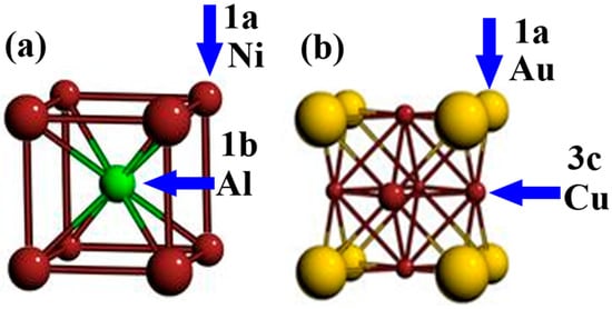
Figure 1.
B2-NiAl and L12-AuCu3 crystal structures referred to as BCC and FCC prototypes.
The chemical reaction process of the formation of FCC_AlCrFeMoTi HEA developed from the corresponding pure elements is presented in Equation (2).
The FCC structural model consists of 100 atomic sites, consisting of two sublattices: 1a (vertex position, 25 sites) and 3c (face center position, 75 sites). Each constituent element randomly occupies 20 atoms at each of the above-mentioned sublattice positions, as shown in Figure 1b.
2.2. Computation Details
In this study, Gibbs free energy calculations were performed using thermodynamic software combined with its High Entropy Alloy (HEA) thermodynamic database. The calculations are based on the sublattice model, and the Gibbs free energy of the system (G) is expressed as
where U represents the internal energy, pV is the product of pressure and volume, T is the temperature, and S denotes the entropy. For solid-state alloy systems, both internal energy and entropy are typically obtained through first-principles calculations.
The Gibbs free energies of the individual phases were evaluated using the CALPHAD (CALculation of PHAse Diagrams) method, which optimizes thermodynamic parameters to fit and predict phase equilibria in multicomponent systems.
The first principles method based on the density functional theory was used to investigate the steady-state phase and electronic structure of AlCrFeMoTi HEA.
Finite element software was used to calculate the steady-state phase structure. A 4 × 4 × 4 supercell model (128 atoms in total) with disordered atomic distribution was constructed for AlCrFeMoTi HEA based on the BCC (B2-NiAl prototype) and FCC (L12-AuCu3 prototype) structures. Subsequently, the conjugate gradient method was used to optimize the structure of the computational thermodynamic stability model, ensuring sufficient relaxation of the structure to ensure configuration stability. The interaction between ions and electrons was described by the projection augmented plane wave (PAW) method []. The generalized gradient approximation (GGA) of Perdew–Burke–Ernzerhof (PBE) was employed to describe exchange correlation energy []. The kinetic cutoff energy was set to be 400 eV. The K-point was set as 2 × 2 × 2 Monkhorst–Pack mesh. The convergence threshold of the electronic step during the optimization process was 1 × 10⁻⁴ eV. Considering the magnetic properties of the alloy during the calculation process, spin polarization calculation was enabled.
The electronic structure was calculated by employing the PAW methods implemented in the DS-PAW program []. The interaction between ions and electrons was described by the PAW method. The Perdew–Burke–Ernzerhof (PBE) functional under generalized gradient approximation (GGA) was employed to describe the exchange correlation energy. A 4 × 4 × 4 BCC structure HEA supercell model containing 128 atoms with disordered atomic distribution obtained from was adopted to calculate the energy band structure, density of states, and charge density of AlCrFeMoTi HEA. Gaussian broadening was used in the calculation process, with a broadening width of 0.05 eV. The K-point sampling scheme was a Gamma center grid with a grid density of 3 × 3 × 3. The plane-wave cutoff energy was set as 500 eV. During the optimization process, the total energy deviation convergence was set to a maximum atomic force of 0.01 eV/Å.
2.3. Experimental Details
A bulk AlCrFeMoTi high-entropy alloy (HEA) sample with an equiatomic ratio (i.e., each element at 20 at.%) was fabricated using Laser-Directed Energy Deposition (LDED). The LDED system consists of a laser generator (maximum power of 6 kW at 1075 nm wavelength), a four-axis coaxial powder feeding laser cladding head, an ABB six-axis robotic arm, a CNC worktable, and a protective gas (argon gas with a purity of 99.95%). The ABB six-axis robotic arm drove the laser cladding head to perform unidirectional scanning back and forth, and carried out multi-pass and multi-layer deposition to prepare bulk AlCrFeMoTi HEA samples. The LDED process parameters were set as follows: laser power of 1200 W, 1300 W, and 1400 W; scanning speed of 10 mm/min; powder feeding rate of 2 r/min; diameter of laser of 3 mm; defocus of 0 mm; protective gas flow rate of 10 L/min; overlap rate of 50%; and single-layer thickness of 0.8 mm. Then, the deposited bulk AlCrFeMoTi HEA was cut into small squares of 10 mm × 10 mm × 10 mm using wire cutting for X-ray diffraction (XRD) testing. The phase of the deposited AlCrFeMoTi HEA was characterized by XRD (Panalytical, Empyren) using Cu Ka radiation. The diffractometer was operated at 30 mA and 40 kV. The diffraction angle (2θ) was scanned from 20° up to 90°. The scan rate and the step size were set as 5°/min and 0.02°.
3. Results and Discussion
3.1. Thermodynamic Stability Analysis: Comparison of BCC and FCC
3.1.1. Gibbs Free Energy
In this study, thermodynamic software was used to calculate the Gibbs free energy of AlCrFeMoTi HEA formation with BCC and FCC phases. The calculated Gibbs free energy of AlCrFeMoTi HEAs with BCC and FCC phases varies with temperature, as shown in Figure 2. The calculation results indicate that at temperatures below 1150 K, the Gibbs free energy formed by BCC_AlCrFeMoTi HEA is lower than that of FCC_AlCrFeCoTi HEA. This indicates that the BCC phase of AlCrFeMoTi HEA is more stable. The low valence electron concentration of Cr, Mo, and Ti refractory alloying elements in this HEA is a key factor for the stability of the BCC phase.
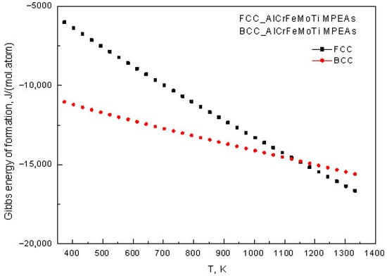
Figure 2.
The relationship between the Gibbs free energy of BCC_AlCrFeMoTi HEA and FCC_AlCrFeMoTi HEA and temperature.
3.1.2. Sublattice Occupancy Characteristics
The site occupancy fractions of the alloying atoms on different sublattices for BCC and FCC phases were calculated. Figure 3 shows the temperature-dependent site occupancy fractions of AlCrFeMoTi HEA in the BCC phase. The data in the figure indicates that BCC_AlCrFeMoTi HEA has a significant temperature-dependent occupancy pattern. Fe, Mo, and Cr atoms preferentially occupy the 1a sublattice, while Al and Ti atoms tend to be distributed in the 1b sublattice. The site occupancy fractions of Al, Cr, and Mo undergo significant changes with increasing temperature (fluctuation amplitude > 15%). Especially, the site occupancy fraction of the 1b sublattice of the Mo atom decreases by 22% at 1300 K compared to 400 K. This indicates that the sublattice migration of BCC_AlCrFeMoTi HEA is temperature-sensitive. Moreover, the figure indicates that the site occupancy behaviors change gradually from an ordered state to a disordered state with the increase in temperature.
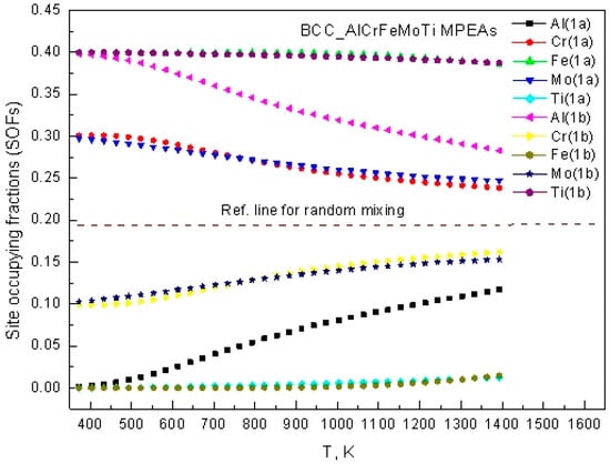
Figure 3.
The temperature-dependent site occupancy fractions of BCC_AlCrFeMoTi HEA.
Figure 4 reveals the differential distribution of atomic occupying fractions of Al, Cr, Fe, Mo, and Ti in the FCC phase. From the figure, it can be seen that Al atoms mainly occupy the 1a sublattice; Cr, Fe, and Ti atoms preferentially occupy the 3c sublattice; while Mo has similar occupancy probabilities in the 1a and 3c sublattices. It is not difficult to observe that the occupancy tendencies of all five elements remain relatively stable during temperature changes, with a maximum fluctuation range of <8% in the temperature range of 300 K to 1400 K. This indicates that the FCC_AlCrFeMoTi HEA has a wider temperature adaptation window.
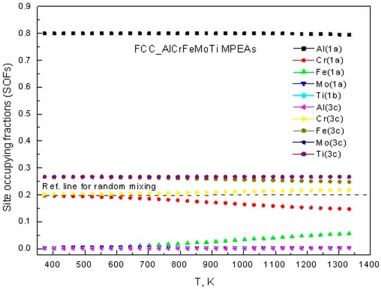
Figure 4.
The temperature-dependent site occupancy fractions of FCC_AlCrFeMoTi HEA.
3.1.3. Experimental Validation
The XRD patterns of the deposited AlCrFeMoTi HEA prepared by different laser powers are shown in Figure 5. The XRD patterns indicate that the BCC phase, FCC phase, B2 phase, Laves phase, and σ phase have been identified. It is not difficult to observe that the diffraction peak of the BCC phase is significantly stronger than that of the FCC phase. Thermodynamic calculations focus on the BCC and FCC primary phases because, in the initial phase diagram screening of the AlCrFeMoTi system, these two solid solution phases are the primary competing phases. However, the experimental XRD results indicate that secondary phases such as B2, Laves, and σ phases form under rapid solidification conditions, which is primarily attributed to the non-equilibrium processing conditions. Gibbs free energy calculations show that the BCC phase is more stable over a wide temperature range, which is consistent with the experimental observation that the BCC diffraction peak intensity consistently dominates. This suggests that, despite the presence of secondary phases, the BCC phase remains the fundamental stable phase in this alloy system. Moreover, as the laser power increases, the diffraction peak intensity of the BCC phase gradually increases. The AlCrFeMoTi HEA prepared by a laser power of 1400 W develops a (110) diffraction peak with high diffraction intensity and wide peak broadening. This indicates that higher laser power results in BCC phases with higher crystallinity and smaller grain size. With the increase in laser power, the energy absorbed by the molten pool increases, and the temperature of the molten pool rises, forming a larger temperature gradient, which is more conducive to the formation of smaller BCC phases.
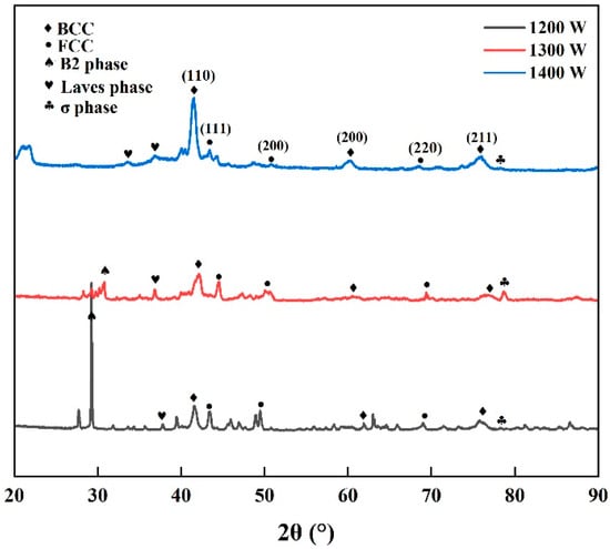
Figure 5.
XRD patterns of bulk AlCrFeMoTi HEA prepared by different laser powers.
3.2. Structural Optimization and Lattice Distortion
Based on the results of steady-state phase structure analysis, an atom distribution model was constructed, and structural optimization calculations were carried out for the AlCrFeMoTi HEA with a BCC phase structure. Based on the site preference of atoms occupying sublattices [], a 4 × 4 × 4 type B2-NiAl supercell (128 atomic sites, 64 1a/1b sublattices each) was used to construct the atom distribution model of AlCrFeMoTi HEA. The results indicate that the alloying atom has an obvious site preference. Fe, Mo, and Cr atoms tend to prefer being located in the 1a sublattice, while Al and Ti atoms tend to prefer being located in the 1b sublattice. This is consistent with the calculation results in Figure 3. At 973 K, the final configuration is (Al5Cr16Fe26Mo17Ti0)1a(Al21Cr9Fe0Mo9Ti25)1b, as shown in Figure 6.
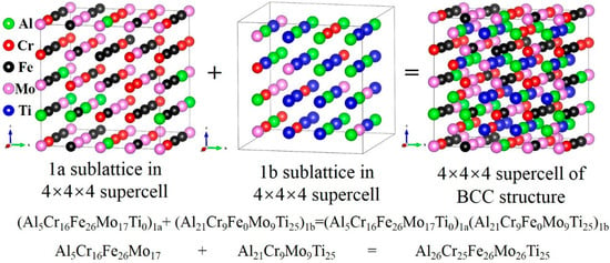
Figure 6.
The 4 × 4 × 4 supercell for BCC_AlCrFeMoTi HEA with sublattice nested at 937 K.
After the initial structure relaxation, the crystal framework maintains the BCC structure, but there is a weak lattice distortion, and the atoms exhibit ordered distribution characteristics (as shown in Figure 7). The difference in sublattice occupancy (such as Fe enrichment in 1a and Ti enrichment in 1b) leads to local bond length recombination, causing initial strain in the lattice.

Figure 7.
Atomic distribution diagrams of three principal plane views of BCC_AlCrFeMoTi HEA at 973 K.
The atomic distribution after volume optimization is shown in Figure 8. As shown in the figure, it can be observed that some atoms deviate from the lattice position. The maximum atomic displacement reaches 0.38 Å, which reflects the accumulation of lattice strain. The maximum lattice strain energy released is Δ E = −2.7 eV. This indicates that volume optimization effectively reduces system energy, laying the foundation for subsequent distortion release.
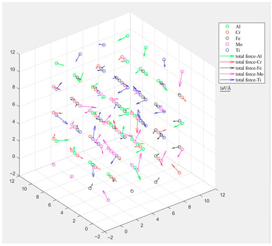
Figure 8.
Atomic distribution after volume optimization.
The structure after complete relaxation is shown in Figure 9. From the figure, it can be seen that a stable distorted configuration is formed after complete relaxation, resulting in a stretched supercell along the <001> direction (c/a = 1.02). The distortion energy of this configuration is significantly positively correlated with the difference in atomic radius (such as Ti with an atomic radius of 1.47 Å and Cr with an atomic radius of 1.28 Å). The essence of its strengthening mechanism is reflected in the fact that atomic size differences dominate lattice distortion, inducing tensile strain and local shear strain along the <001> direction through sublattice occupancy specificity distribution (such as Ti enrichment in the 1b sublattice), directly hindering dislocation movement. Simultaneously, the release of distortion energy and electron redistribution (Al-Cr electron cloud overlap enhances local covalent bonds) synergistically stabilize the distorted configuration, ultimately improving the mechanical properties of the material. This is in line with the core mechanism of the distortion–strengthening theory of HEAs.
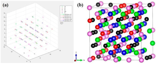
Figure 9.
(a) Atomic distribution, (b) steady-state structure after complete relaxation of AlCrFeMoTi HEA.
3.3. Electronic Structure
Figure 10 shows the energy band structure of AlCrFeMoTi HEA along with the highly symmetric direction of the Brillouin region. The green dotted line in the figure represents the position of the Fermi energy level. The energy band structure near the Fermi level is closely related to material properties. As shown in the figure, due to the overlap between the conduction band and valence band, the energy gap is zero, indicating that AlCrFeMoTi HEA exhibits metallic properties. At the same time, the image shows that the energy band of the AlCrFeMoTi HEA is compact, which may be due to the strong interaction of orbital electrons between atoms.
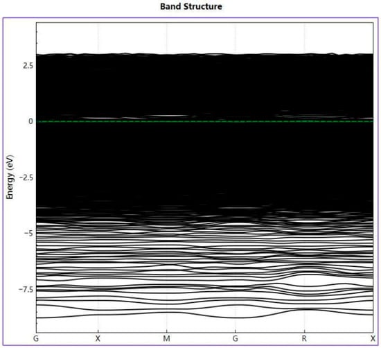
Figure 10.
Energy band structure of AlCrFeMoTi HEA.
Figure 11 shows the total and partial densities of state of AlCrFeMoTi HEA. As shown in the picture, the strong peak energies near the Fermi level of AlCrFeMoTi HEA are −1.44 eV and 1.05 eV. That is to say, the pseudo-energy gap of AlCrFeMoTi HEA is 2.49 eV. Pseudo-energy gap, defined as the energy difference between two strong peaks near the Fermi level, reflects the covalent nature of the alloy system. The wider the pseudo-energy gap, the stronger the covalency of the alloy system [,]. The partial density of states of the Al, Cr, Fe, Mo, and Ti elements in Figure 11 shows the contribution of the electrons of these five elements to the total density of states of the AlCrFeMoTi HEA. It can be clearly observed from the figure that the d-orbital electrons of the Fe element contribute the most to the total density of states, followed by the d-orbital electrons of the Cr and Ti elements, and then the d-orbital electrons of the Mo element. The contribution of the three orbital electrons of the Al element is the smallest. In addition, it can be seen that the valence band near the Fermi level of AlCrFeMoTi HEA is formed after the hybridization of d-orbital electrons of Cr, Fe, Mo, and Ti, with a high overlap rate. The density of states calculation results indicate that the valence band of AlCrFeMoTi HEA is close to the Fermi level, and the number of covalent bonds between atoms is relatively small, which may lead to an increase in metal bonds. The high total density of states of AlCrFeMoTi HEA indicates its strong metallic properties.
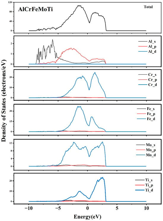
Figure 11.
The total and partial density of states of AlCrFeMoTi HEA.
Figure 12 shows the charge density and charge density difference diagram of AlCrFeMoTi HEA along the crystal plane (110). The charge density can directly reflect the bonding and charge transfer between atoms. As shown in the charge density diagram, the electron cloud is uniformly distributed around the Al, Cr, Ti, Fe, and Mo atoms without obvious directionality. This confirms the formation of metal bonds. Among them, the electron cloud overlap between the Al atoms and Cr atoms is stronger, indicating stronger electronic interactions between the Al and Cr atoms. In the charge density difference diagram, the red represents receiving electrons and the green represents losing electrons. It can be seen from the figure that Al loses electrons, while Mo and Ti gain electrons.
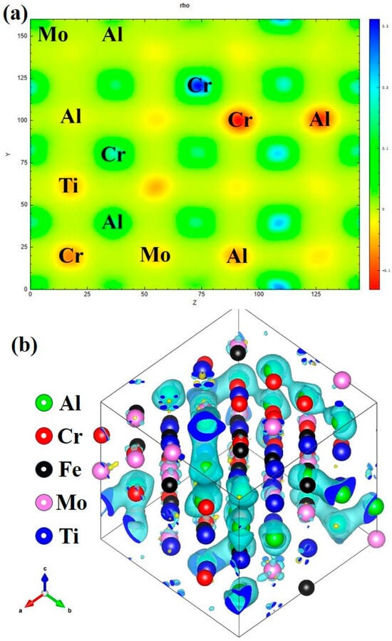
Figure 12.
(a) The charge density, (b) the charge density difference diagram of AlCrFeMoTi HEA along the crystal plane (110).
4. Conclusions
In this present study, first-principles calculation was used to investigate the steady-state phase and electronic structure of AlCrFeMoTi HEA. The following conclusions can be drawn:
- (1)
- The Gibbs free energy formed by the BCC phase was lower than that of the FCC phase for AlCrFeMoTi HEA. The XRD results show that the diffraction peak of the BCC phase is significantly stronger than that of the FCC phase. It implies that the BCC phase is more stable for AlCrFeMoTi HEA.
- (2)
- The calculation results of the atomic distribution model show that alloy atoms have obvious site preferences. Among them, Fe, Mo, and Cr atoms tend to be located in the 1a sublattice, while Al and Ti atoms tend to be located in the 1b sublattice. The atom site occupancy is temperature-sensitive. At 973 K, the site occupancy configuration is (Al5Cr16Fe26Mo17Ti0)1a(Al21Cr9Fe0Mo9Ti25)1b.
- (3)
- The lattice distortion after structural optimization achieved a strengthening mechanism through atomic size differences and occupancy specificity. The maximum lattice strain energy released was Δ E = −2.7 eV.
- (4)
- The band structure displayed the overlap between the conduction band and valence band, with a zero bandgap. The total density of states of AlCrFeMoTi HEA was relatively high, with strong peak energies near the Fermi level at −1.44 eV and 1.05 eV, resulting in a pseudo-bandgap of 2.49 eV. The electron cloud was uniformly distributed around the alloy element atoms without obvious directionality. All of these indicate the formation of metal bonds, and AlCrFeMoTi HEA had strong metallic properties.
Author Contributions
Software, X.H. and Y.L.; Writing—original draft, W.X.; Writing—review & editing, S.Z. and J.H.; Visualization, Y.W. All authors have read and agreed to the published version of the manuscript.
Funding
This work was supported by the Hunan Provincial Education Bureau Scientific Research Foundation (22B0462) and the Reactor System Design Technology Laboratory Science and Technology Operation Fund (KFKT-05-FWHT-WU-2023002).
Data Availability Statement
The original contributions presented in this study are included in the article. Further inquiries can be directed to the corresponding authors.
Acknowledgments
The authors are grateful to other participants of the project for their cooperation. And the authors gratefully acknowledge the computational convenience provided by HZWTECH. We also thank Bo Wu (School of Materials Science and Engineering, Fuzhou University, Fuzhou 350100, China) for his technical support and guidance.
Conflicts of Interest
The funders had no role in the design of the study; in the collection, analyses, or interpretation of data; in the writing of the manuscript; or in the decision to publish the results.
References
- Qiu, M.I.; Huang, P.; Gu, C.; Wang, F. Achieving superior strength-ductility synergy in refractory high entropy alloy. Intermetallics 2025, 183, 108794. [Google Scholar] [CrossRef]
- Ghasemi, A.; Eivani, A.R.; Abbasi, S.M.; Jafarian, H.R.; Ghosh, M.; Anijdan, S.H.M. Al-Co-Cr-Fe-Ni-Ti high entropy alloys: A review of microstructural and mechanical properties at elevated temperatures. J. Alloys Compd. 2025, 1010, 178216. [Google Scholar] [CrossRef]
- Li, S.; Liu, X.; Hou, X.; Liu, Z.; Wang, X.; Narayanan, J.A.; Wu, T.; Bai, Y.; Dong, Y.; Jiang, H. Evolution of corrosion mechanism of 3d transition metal high entropy alloys: A review. J. Mater. Res. Technol. 2025, 35, 4142–4163. [Google Scholar] [CrossRef]
- Wang, S.B.; Wu, M.X.; Shu, D.; Zhu, G.L.; Wang, D.H.; Sun, B.D. Mechanical instability and tensile properties of TiZrHfNbTa high entropy alloy at cryogenic temperatures. Acta Mater. 2020, 201, 517–527. [Google Scholar] [CrossRef]
- Chen, Z.; Zhang, S.; Jiang, X.; Zheng, M.; Yang, H.; Sun, Y.; Li, G. Properties and applications of deuterium absorption-deposition in TiZrHfNbTa high entropy alloy. J. Nucl. Mater. 2025, 615, 155987. [Google Scholar] [CrossRef]
- He, C.; Li, Y.; Zhou, Z.; Liu, B.; Gao, X. High-entropy photothermal materials. Adv. Mater. 2024, 36, 2400920. [Google Scholar] [CrossRef]
- Ren, J.; Chen, L.; Wang, H.; Yuan, Z. High-entropy alloys in electrocatalysis: From fundamentals to application. Chem. Soc. Rev. 2023, 52, 8319–8373. [Google Scholar] [CrossRef]
- Zhang, L.; Xu, Y.; Li, X. First-principles study of intermetallic compounds In CrMnFeCoNiZr system high-entropy alloy. Int. J. Mod. Phys. B 2017, 31, 1744007. [Google Scholar] [CrossRef]
- Liu, R.; Lu, R.; Wang, A.; Zhu, Z.; Wang, H. First-principles study on local site preference of interstitial oxygen in Ti3Zr1.5NbVAl0.25 high-entropy alloy. Comput. Mater. Sci. 2025, 253, 113867. [Google Scholar] [CrossRef]
- Lian, G.; Chen, J.; Yang, J.; Feng, M.; Lan, S. Influences of element M (M = Mo, Cu, and Al) on CoCrFeNiTi-based high entropy alloys by laser cladding under different process parameters. Intermetallics 2025, 176, 108572. [Google Scholar] [CrossRef]
- Zhang, J.; Li, N. Review of the studies on fundamental issues in LBE corrosion. J. Nucl. Mater. 2008, 373, 351–377. [Google Scholar] [CrossRef]
- Kondo, M.; Takahashi, M.; Sawada, N.; Hata, K. Corrosion of steels in lead-bismuth flow. J. Nucl. Sci. Technol. 2006, 43, 107–116. [Google Scholar] [CrossRef]
- Zhang, W.; Deng, J.; Zhong, Y.; Zhou, M.; Qiu, X.; Zhou, Y.; Yang, J. Research progress on LBE corrosion-resistant coatings: A review. Prog. Nucl. Energy 2024, 176, 105358. [Google Scholar] [CrossRef]
- Gong, X.; Short, M.P.; Auger, T.; Charalampopoulou, E.; Lambrinou, K. Environmental degradation of structural materials in liquid lead- and lead-bismuth eutectic-cooled reactors. Prog. Mater. Sci. 2022, 126, 100920. [Google Scholar] [CrossRef]
- Zhong, Y.; Yang, J.; Zhang, W.; Wu, J.; Yong, L.; Liu, N.; Yang, J. Investigation of mechanical properties and lead-bismuth eutectic corrosion resistance of Al2O3 coatings doped silicon. J. Mater. Res. Technol. 2025, 36, 9079–9090. [Google Scholar] [CrossRef]
- Wan, Q.; Wu, Z.Y.; Liu, Y.; Yang, B.; Liu, H.D.; Ren, F.; Wang, P.; Xiao, Y.Y.; Zhang, J.; Zhang, G.D. Lead-bismuth eutectic (LBE) corrosion mechanism of nano-amorphous composite TiSiN coatings synthesized by cathodic arc ion plating. Corros. Sci. 2021, 183, 109264. [Google Scholar] [CrossRef]
- Guo, S.; Liu, L.; He, F.; Wang, S. Preparation of Cr-N coatings on 316H stainless steel via pack chromizing and gas nitriding, and their resistance to liquid metal corrosion in early stages. Surf. Coat. Technol. 2024, 481, 130665. [Google Scholar] [CrossRef]
- Glasbrenner, H.; Gröschel, F. Exposure of pre-stressed T91 coated with TiN, CrN and DLC to Pb–55.5Bi. J. Nucl. Mater. 2006, 356, 213–221. [Google Scholar] [CrossRef]
- Kurata, Y.; Sato, H.; Yokota, H.; Suzuki, T. Applicability of Al-powder-alloy coating to corrosion barriers of 316SS in liquid lead-bismuth eutectic. Mater. Trans. 2011, 52, 1033–1040. [Google Scholar] [CrossRef]
- Wang, L.; Liao, Q.; Zhang, J.; Liu, S.; Gan, S.; Wang, R.; Ge, F.; Chen, L.; Xu, S.; Polcar, T.; et al. Corrosion behavior of Cr coating on ferritic/martensitic steels in liquid lead-bismuth eutectic at 600 °C and 700 °C. J. Mater. Res. Technol. 2024, 29, 3958–3966. [Google Scholar] [CrossRef]
- Rivai, A.K.; Takahashi, M. Corrosion investigations of Al-Fe-coated steels, high Cr steels, refractory metals and ceramics in lead alloys at 700 °C. J. Nucl. Mater. 2010, 398, 146–152. [Google Scholar] [CrossRef]
- Zhang, W.; Deng, J.; Zhou, M.; Zhong, Y.; Wu, L.; Mao, J.; Xu, X.; Zhou, Y.; Yang, J. Synergistic effect of simultaneous proton irradiation and LBE corrosion on the microstructure of the FeCrAl (Y) coatings. Corros. Sci. 2024, 229, 111874. [Google Scholar] [CrossRef]
- Zhou, M.; Zhang, W.; Deng, J.; Long, Z.; Zhong, Y.; Wang, R.; Liu, H.; Li, Y.; Li, X.; Yang, J. Insights into corrosion mechanism of FeCrAlY coating in oxygen-poor static and flowing LBE. Corros. Sci. 2024, 241, 112546. [Google Scholar] [CrossRef]
- Yang, J.; Zhang, F.; Zhai, L.; Qu, G.; Yang, J. Microstructure, mechanical and oxygen-deficient lead-bismuth eutectic corrosion properties of FeCrAlTiMo high-entropy alloy coatings for fuel claddings. Intermetallics 2024, 175, 108533. [Google Scholar] [CrossRef]
- Deng, J.; Yang, J.; Lv, L.; Zhang, W.; Chen, Q.; Zhou, M.; Zhu, C.; Liu, N.; Yang, J. Corrosion behavior of refractory TiNbZrMoV high-entropy alloy coating in static lead-bismuth eutectic alloy: A novel design strategy of LBE corrosion-resistant coating? Surf. Coat. Technol. 2022, 448, 128884. [Google Scholar] [CrossRef]
- Li, S.; Sun, L.; Cheng, S.; Gong, A.; Yang, W.; Tong, Z. General corrosion behavior and mechanism of ferritic/martensitic steel with and without TaWVCr coating in static oxygen-saturated lead bismuth eutectic at 550 °C. Surf. Coat. Technol. 2024, 488, 131038. [Google Scholar] [CrossRef]
- Zhang, L.; Dou, Y.; Bai, B.; Yu, B.; He, X.; Yang, W. Research progress on creep resistance of high entropy alloys. J. Alloys Compd. 2025, 1011, 178280. [Google Scholar] [CrossRef]
- Lu, Y.; Huang, H.; Gao, X.; Ren, C.; Gao, J.; Zhang, H.; Zheng, S.; Jin, Q.; Zhao, Y.; Lu, C.; et al. A promising new class of irradiation tolerant materials: Ti2ZrHfV0.5Mo0.2 high-entropy alloy. J. Mater. Sci. Technol. 2019, 35, 369–373. [Google Scholar] [CrossRef]
- Walczak, M.; Nowak, W.J.; Szala, M.; Grądzka-Dahlke, M.; Maciaszek, N.; Vališ, D.; Pasierbiewicz, K. Effect of molybdenum addition on microstructure and behavior of AlCoCrFeNi high-entropy alloys in wet environments. Arch. Civ. Mech. Eng. 2025, 25, 1–22. [Google Scholar] [CrossRef]
- Xu, Z.; Sun, Z.; Li, C.; Wang, Z. Effect of Cr on Microstructure and Properties of WVTaTiCr x Refractory High-Entropy Alloy Laser Cladding. Materials 2023, 16, 3060. [Google Scholar] [CrossRef]
- Yang, J.; Zhang, F.; Chen, Q.; Zhang, W.; Zhu, C.; Deng, J.; Zhong, Y.; Liao, J.; Yang, Y.; Liu, N.; et al. Effect of Au-ions irradiation on mechanical and LBE corrosion properties of amorphous AlCrFeMoTi HEA coating: Enhanced or deteriorated? Corros. Sci. 2021, 192, 109862. [Google Scholar] [CrossRef]
- Yang, J.; Shi, K.; Zhang, W.; Chen, Q.; Ning, Z.; Zhu, C.; Liao, J.; Yang, Y.; Liu, N.; Yang, J. A novel AlCrFeMoTi high-entropy alloy coating with a high corrosion-resistance in lead-bismuth eutectic alloy. Corros. Sci. 2021, 187, 109524. [Google Scholar] [CrossRef]
- Nguyen, V.-L.; Doan, M.-Q.; Hue, D.T.H.; Dinh, V.-H.; Van Lich, L. Mechanical hebavior of high entropy alloys with gyroid nanostructures. Intermetallics 2024, 171, 108348. [Google Scholar] [CrossRef]
- Nene, S.; Sinha, S.; Yadav, D.; Dutta, A. Metallurgical aspects of high entropy alloys. J. Alloys Compd. 2024, 1005, 175849. [Google Scholar] [CrossRef]
- Zheng, C.; Wang, Q.; Chen, R.; Wei, W.; Ding, X.; Fu, H. Greatly improving corrosion resistance of Ti alloy by regulating basketweave microstructure and phase electronic structure. Corros. Sci. 2025, 249, 112836. [Google Scholar] [CrossRef]
- Jiang, C.; Sordelet, D.; Gleeson, B. A first-principles study of the site preference of Cr in B2 NiAl. Scr. Mater. 2006, 54, 405–410. [Google Scholar] [CrossRef]
- Nong, Z.; Zhu, J.; Zhao, R. Prediction of structure and elastic properties of AlCrFeNiTi system high entropy alloys. Intermetallics 2017, 86, 134–146. [Google Scholar] [CrossRef]
- Avula, I.; Chavan, A.; Mukherjee, S.; Roy, M. Phase stability and mechanical properties of Ta enriched TiTaNbZrMo refractory high entropy alloys. J. Alloys Compd. 2024, 989, 174408. [Google Scholar] [CrossRef]
- Wu, Y.; Zhang, Y.; Li, Z.; Liu, Z.; Zhao, E.; Liu, J. Prediction of NbTaTiZr-based high-entropy alloys with high strength or ductility: First-principles calculations. J. Mater. Res. Technol. 2024, 30, 8854–8861. [Google Scholar] [CrossRef]
- Lu, C.; Zhang, Y.; Wang, Y.; Cheng, B.; Ma, T.; Shao, T. A first-principles study on the structural stability and mechanical properties of TiZrVNbMo refractory high-entropy alloys. Comput. Mater. Sci. 2025, 257, 114006. [Google Scholar] [CrossRef]
- Wu, B.; Zhao, Y.; Ali, H.; Chen, R.; Chen, H.; Wen, J.; Liu, Y.; Liu, L.; Yang, K.; Zhang, L.; et al. A reasonable approach to describe the atom distributions and configurational entropy in high entropy alloys based on site preference. Intermetallics 2022, 144, 107489. [Google Scholar] [CrossRef]
- Kresse, G.; Furthmüller, J. Efficient iterative schemes for ab initio total-energy calculations using a plane-wave basis set. Phys. Rev. B 1996, 54, 11169–11186. [Google Scholar] [CrossRef] [PubMed]
- Perdew, J.P.; Burke, K.; Ernzerhof, M. Generalized gradient approximation made simple. Phys. Rev. Lett. 1996, 77, 3865–3868. [Google Scholar] [CrossRef] [PubMed]
- Blochl, P.E. Projector augmented-wave method. Phys. Rev. B 1994, 50, 17953–17979. [Google Scholar] [CrossRef] [PubMed]
- Wang, Y.; He, J.; Yan, M.; Li, C.; Wang, L.; Zhou, Y. First-principles study of NiAl alloyed with rare earth element Ce. J. Mater. Sci. Technol. 2011, 27, 719–724. [Google Scholar] [CrossRef]
- Hu, Y.; Bai, L.; Tong, Y.; Deng, D.; Liang, X.; Zhang, J.; Li, Y.; Chen, Y. First-principle calculation investigation of NbMoTaW based refractory high entropy alloys. J. Alloys Compd. 2020, 827, 153963. [Google Scholar] [CrossRef]
Disclaimer/Publisher’s Note: The statements, opinions and data contained in all publications are solely those of the individual author(s) and contributor(s) and not of MDPI and/or the editor(s). MDPI and/or the editor(s) disclaim responsibility for any injury to people or property resulting from any ideas, methods, instructions or products referred to in the content. |
© 2025 by the authors. Licensee MDPI, Basel, Switzerland. This article is an open access article distributed under the terms and conditions of the Creative Commons Attribution (CC BY) license (https://creativecommons.org/licenses/by/4.0/).