You are currently viewing a new version of our website. To view the old version click .
Symmetry
  • Article
  • Open Access

11 November 2025

Symmetry in Stress Distribution: Elastic–Plastic Behavior of Rib Plates and Rib-to-Deck Weld Root Performance in Steel Orthotropic Bridge Decks

,
and
1
Department of Structural Engineering, Faculty of Civil Engineering, University of Aleppo, Aleppo 12212, Syria
2
L2MGC, Civil Engineering Mechanics and Materials Laboratory, CY Cergy-Paris University, 95031 Cergy, France
*
Author to whom correspondence should be addressed.
This article belongs to the Special Issue Symmetry, Asymmetry and Other Patterns in Structural Engineering with Its Application

Abstract

This study investigates the mechanical behavior and fatigue performance of orthotropic steel bridge decks, with a focus on rib-to-deck welded connections and the impact of geometric symmetry on stress distribution. Two full-scale models with full-penetration butt welds were tested under static compression loads, yielding failure forces of 27 kN (experimental) and 26 kN (analytical), with only a 3% difference. Finite element simulations using ANSYS 16.1 validated these results and enabled parametric studies. Rib plate thicknesses ranging from 5 mm to 9 mm were analyzed to assess their influence on stress distribution and deformation. The geometric ratio h′/tr, which reflects the symmetry of the trapezoidal rib web, was found to be a critical factor in stress behavior. At h′/tr = 38 (tr = 7 mm), compressive and tensile stresses are balanced, demonstrating a symmetric stress field; at h′/tr = 33 (tr = 8 mm), and fatigue performance at the RDW root drops by 47%. Increasing h′/tr improves fatigue life by increasing the number of load cycles to failure. Stress contours revealed that compressive stress concentrates in the rib plate above the weld toes, while tensile stress localizes at the RDW root. The study highlights how symmetric geometric configurations contribute to balanced stress fields and improved fatigue resistance. Multiple linear regression analysis (SPSS-25) produced predictive equations linking stress values to applied load and geometry, offering a reliable tool for estimating stress without full-scale simulations. These findings underscore the importance of optimizing h′/tr and leveraging structural symmetry to enhance resilience and fatigue resistance in welded joints. This research provides practical guidance for improving the design of orthotropic steel bridge decks and contributes to safer, longer-lasting infrastructure.

1. Introduction

The orthotropic steel deck (OSD) system, developed in Germany in the 1930s, was an innovative solution for long-span bridge structures. It typically employs continuous trapezoidal ribs with spans ranging from 3 to 6 m, allowing them to pass through the webs of the floor beams [,]. This configuration places the rib–deck section in the region of negative bending moments, where the rib plate experiences compressive forces, as illustrated in Figure 1. These compressive load impulses across the rib plate thickness generate vertical bending stresses (σy), which are particularly pronounced at the rib-to-deck welds (RDW) and within the rib plate itself. Symmetry in the geometry of the rib–deck section plays a crucial role in stress distribution. The trapezoidal configuration exhibits bilateral symmetry, which affects the balance between compressive and tensile stresses across the weld and plate.
Figure 1. The studied trapezoid rib–deck section in the negative region.
The rationale for employing the rib–deck section is detailed in Appendix A. The significance of this research lies in identifying the relationship between the stress states in both the rib plate and the root of the rib-to-deck weld (RDW). The primary objective is to develop predictive equations capable of estimating stress values in these critical regions. A key parameter influencing local buckling behavior in the rib plate is the slenderness ratio h′/tr, where h′ represents the inclined length of the trapezoidal rib web and tr denotes the rib plate thickness.
Previous research on this topic has primarily focused on weld performance, often overlooking the stress state in the rib plate, local buckling criteria, and the influence of plate geometry. This study aims to address these gaps. Conversely, other investigations have examined the structural behavior of the plates without considering weld performance. For example, an experimental study on the compressive behavior of OSD plates was conducted based on American and Japanese design recommendations, but it did not analyze the stress state in the welds [].
Numerous rib–deck sections with identical plate dimensions and thicknesses were tested to determine the minimum compatible dimensions for the rib-to-deck welds (RDW). This included evaluating parameters such as weld toe size on the plates, weld penetration depth, percentage of weld intrusion into the rib plate, weld throat size, and overall weld area—particularly in relation to fatigue-induced stresses in the welds. However, the stress state and local buckling criteria of the plates were not considered in the mentioned study. Two types of welds were used in the study: butt welds and filet welds. A multiple linear regression (MLR) analysis was conducted to determine the minimum compatible weld dimensions, based on stress values obtained from both experimental and analytical investigations []. Field observations revealed fatigue cracks originating either from the weld root or propagating through the deck plate [].
The effects of stress concentration due to imperfections at the RDW root were analytically studied using an OSD model based on IIW recommendations. However, the influence of plate geometry was not considered in that analysis []. Although this study focuses on macro-scale mechanical behavior, microstructural investigations using techniques such as scanning electron microscopy (SEM) or optical microscopy have proven effective in identifying weld zone inhomogeneities and crack initiation mechanisms. Including such methods in future work would enrich the understanding of RDW fatigue behavior and complement the mechanical analysis.
Experimental tests involving static tension and compression loads were applied to the rib plate of a trapezoidal rib–deck section to evaluate RDW shear performance under varying values of the rib’s major base width (b). Tension loads led to RDW shear failure, whereas compression loads caused deformation in the rib plate without significantly affecting the RDW. Consequently, the results from compression loading were excluded from the study. Additionally, variations in the rib plate slenderness ratio (h′/tr) were not considered, and no analytical study was conducted on the compressed section with full penetration butt welds []. Fatigue tests were conducted using models simulating the diaphragm zone in the OSD system, which incorporates U-ribs with double-sided welds. The results revealed that the interior weld toe of the U-rib-to-top-plate joint is the region most affected by fatigue. The study identified cracks initiating at the rib-to-diaphragm welds and propagating through the diaphragm plate [].
Analytical models based on rib–deck sections were used to investigate the influence of asphalt pavement layer temperature on RDW fatigue performance. The fatigue crack growth was analyzed using the Linear Elastic Fracture Mechanics (LEFM) theory. The findings indicated a shorter fatigue life at elevated pavement temperatures []. Furthermore, the critical role of residual stresses in assessing the fatigue reliability of rib-to-deck double-sided welded joints in orthotropic steel deck systems was highlighted. A Monte Carlo simulation was performed using analytical models of the OSD system, providing a framework for evaluating fatigue reliability while accounting for welding-induced residual stresses []. Fatigue performance of transverse cracks initiating at the weld root and propagating through the weld throat was experimentally investigated following repair using bonded angle steel. Two groups of test specimens were considered: an unreinforced reference group and a strengthened group with bonded angle steel. Under lateral fatigue loading, the stress amplitude at the U-rib weld root was significantly reduced in the reinforced specimens [].
The influence of residual stresses in single-sided full-penetration RDWs in orthotropic steel decks was studied through both experimental testing and numerical simulation. Results revealed peak tensile stresses near the welds. Residual stresses on the deck surface and the U-rib surface were found to increase with greater plate thickness and higher welding speeds []. Additionally, the fatigue performance of rewelded rib-to-deck weld cracks—repaired from the deck surface—was analyzed. Parameters such as local strain, crack size, fatigue life, and crack propagation behavior were examined. The results showed that rewelding restored the original stress performance; however, the crack size and its growth after secondary cracking were greater than those observed in the unrewelded specimens [].
The influence of residual stresses on the fatigue behavior of orthotropic steel deck (OSD) systems has also been extensively studied. Several analytical models were developed using finite element software, incorporating the rain flow counting algorithm in accordance with ASTM standards. The results demonstrated that residual stresses significantly reduce the fatigue life of OSD systems []. The flexural behavior of a proposed Orthotropic Steel–Lightweight Ultra-High-Performance Concrete Composite Bridge Deck (OS-LUHPC-CBD) was investigated both experimentally and numerically. It was compared with a conventional Orthotropic Steel–Ultra-High-Performance Concrete Composite Bridge Deck (OS-UHPC-CBD), which uses high-strength Q425 steel and trapezoidal ribs. Using an OSD model, the study showed that the proposed OS-LUHPC-CBD exhibited greater ductility and flexural capacity than the OS-UHPC-CBD. Moreover, the OS-LUHPC-CBD enables the construction of long-span bridges with lower cost and weight, while maintaining similar construction feasibility to the OS-UHPC-CBD []. An analytical study was conducted on the buckling behavior of orthotropic steel decks using U-ribs, employing a nonlinear finite element model of a long-span suspension bridge. The study considered key parameters such as initial geometric imperfections, residual stresses, and traffic loading. Results showed that all these factors significantly influence buckling behavior. The use of Ultra-High-Performance Concrete (UHPC) overlay was found to enhance buckling strength [].
The effect of multiaxial traffic loading on the fatigue performance of RDWs was investigated using the Path-Dependent Maximum Stress Range (PDMR) method within an OSD model. The PDMR method predicted high fatigue damage and was therefore recommended for fatigue assessment [].
Despite these contributions, none of the previous studies have explored the relationship between the mechanical behavior of the plates and welds in orthotropic steel decks. Specifically, no study has attempted to link the stress states in both the rib plate and the RDW root. It is essential to begin considering the impact of local buckling standards in the plates on the stress distribution in both the welds and the plates. Accordingly, this study investigates the influence of variations in the local buckling standard of the trapezoidal rib plate on RDW root performance, establishing a direct link between the stress states in the rib plate and the RDW root.

2. Materials and Methods

Low-carbon steel A572 Grade 50 was used in this study, with a yield strength of 345 MPa. To verify its mechanical properties, a tensile test was conducted on a sample plate with a thickness of 5 mm, as shown in Figure 2a. The experiment was performed in the Construction Materials Laboratory at the Faculty of Civil Engineering, Aleppo University, as illustrated in Figure 2b.
Figure 2. Composite figure showing (a) the steel sample used for tensile testing; (b) the sample under tension until failure.
The results of the tensile test showed a yield stress of 335 MPa, an ultimate tensile strength of 447 MPa, and a strain at failure of 24% []. Two models, R1 and R′1, were constructed as shown in Figure 3a, using identical plate dimensions listed in Table 1. Each model incorporated a 100% penetration butt weld for the RDW, executed with an E6013 electrode (yield strength 410 MPa) [], and a minimum weld thickness equal to tr [], as illustrated in Figure 3b.
Figure 3. Composite figure showing (a) the experimental models used in the study []; (b) the configuration of the butt rib-to-deck weld (RDW).
Table 1. The experimental model dimensions [].
The mechanical properties of the weld metal were not experimentally tested in this study. Instead, the yield stress of 410 MPa was adopted from manufacturer specifications [], consistent with its widespread use in orthotropic steel deck systems. Also, this approach aligns those taken in other studies [].
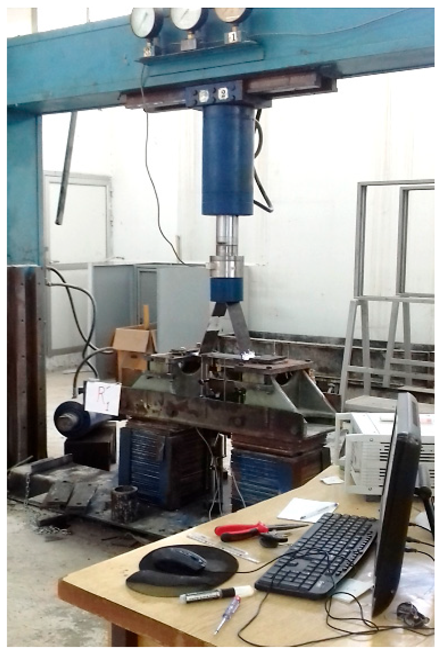
A monotonically increasing static compression load (F) was applied to the top of the rib plate until deformation-induced failure occurred as shown in Figure 4. This loading condition was selected to simulate the compressive stress state in the negative bending moment region of orthotropic steel bridge decks, where the rib plate is primarily subjected to quasi-static compressive forces. While in-service decks experience cyclic loading, the static loading test enables clearer identification of stress zones and yielding behavior, which are essential for calibrating the finite element model and understanding fatigue initiation.
Figure 4. Applying static compression load.
The model was simply supported over a span of 380 mm, consistent with the laboratory configuration. This boundary condition was selected to replicate the experimental setup and ensure accurate calibration of the analytical model. While it does not fully represent the complex restraint conditions of orthotropic bridge decks in situ, where panels are typically supported by transverse beams and diaphragms, it provides a simplified framework for isolating local stress behavior near RDW.
The influence of global deck constraints on local stress fields is expected to be limited in this context, as the stress concentration and yielding behavior are primarily governed by the geometry of the rib plate and weld configuration. Therefore, the simply supported condition is considered sufficient for evaluating the mechanical response and validating the influence of the h′/tr ratio.
This loading configuration was chosen to simulate the stress state in the negative bending region of orthotropic steel decks, particularly in the cross-region near the floor beam, where the rib plate is subjected to compressive forces. Although real bridge decks experience bending along the rib direction due to traffic loads, applying direct compression in the experiment allows controlled investigation of local stress distribution and weld root behavior under compressive conditions. This simplification is consistent with previous studies and helps isolate the influence of geometric parameters such as the h′/tr ratio.
The simply supported boundary condition was selected to replicate the structural behavior of the rib–deck section in the negative bending region of orthotropic steel bridge decks, particularly near the floor beam intersection. In real bridge service conditions, this region experiences compressive stresses due to bending, and the support configuration allows for a realistic simulation of load transfer and deformation. This setup also facilitates controlled observation of stress distribution and failure mechanisms in the RDW root and rib plate.
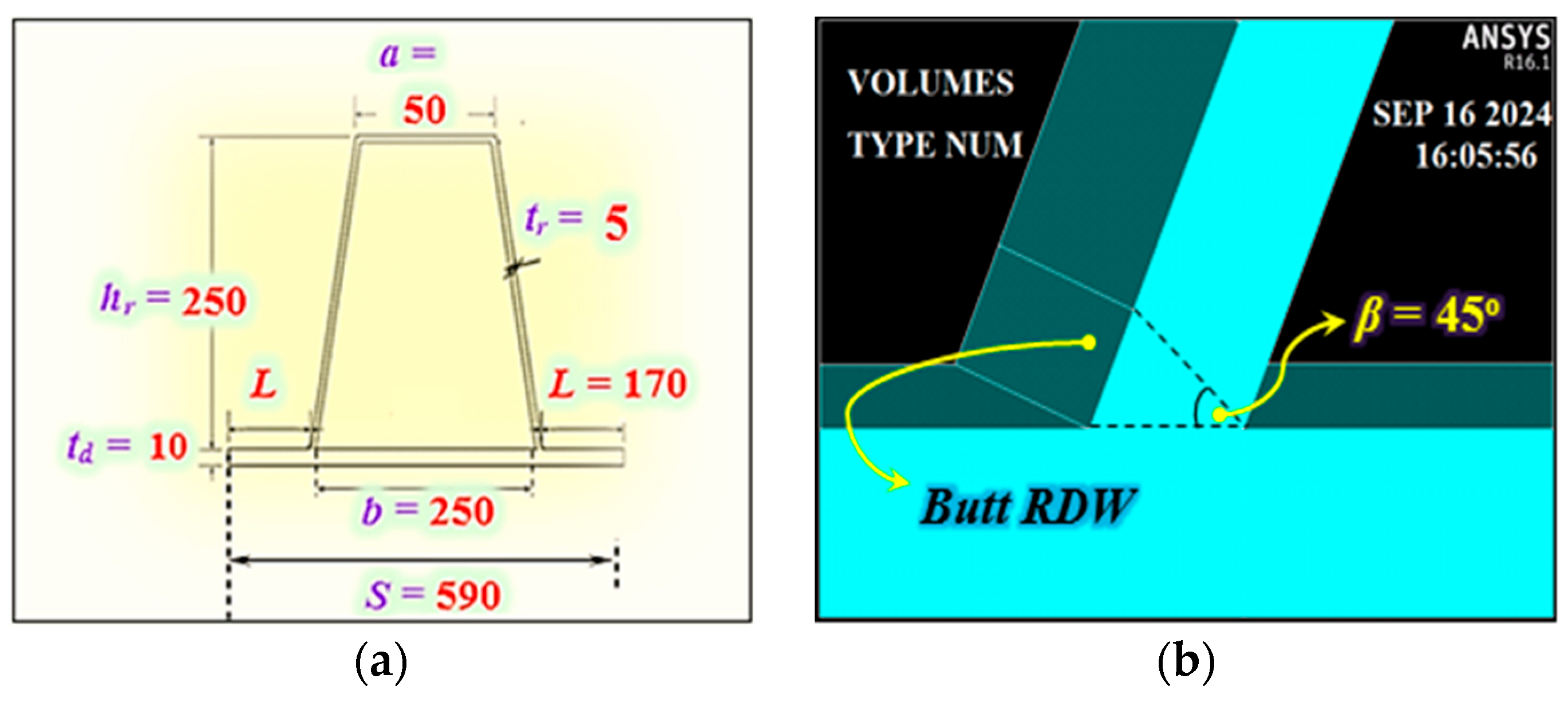
An analytical model replicating the experimental setup was developed using ANSYS 16.1, incorporating the same material properties: yield stress (fy) = 335 MPa for the plates and (fy) = 410 MPa for the welds, with Young’s modulus (E) = 200,000 MPa and Poisson’s ratio (ν) = 0.3. The modeling process began by defining key points at specific distances based on the plate and RDW dimensions, as illustrated in Figure 5a. The butt welds were modeled with a minimum thickness equal to tr, and a weld angle β = 45°, following the specifications in [], as shown in Figure 5b.
Figure 5. Composite figure showing (a) the geometric dimensions of the analytical model; (b) the weld angle and thickness of the butt RDW.
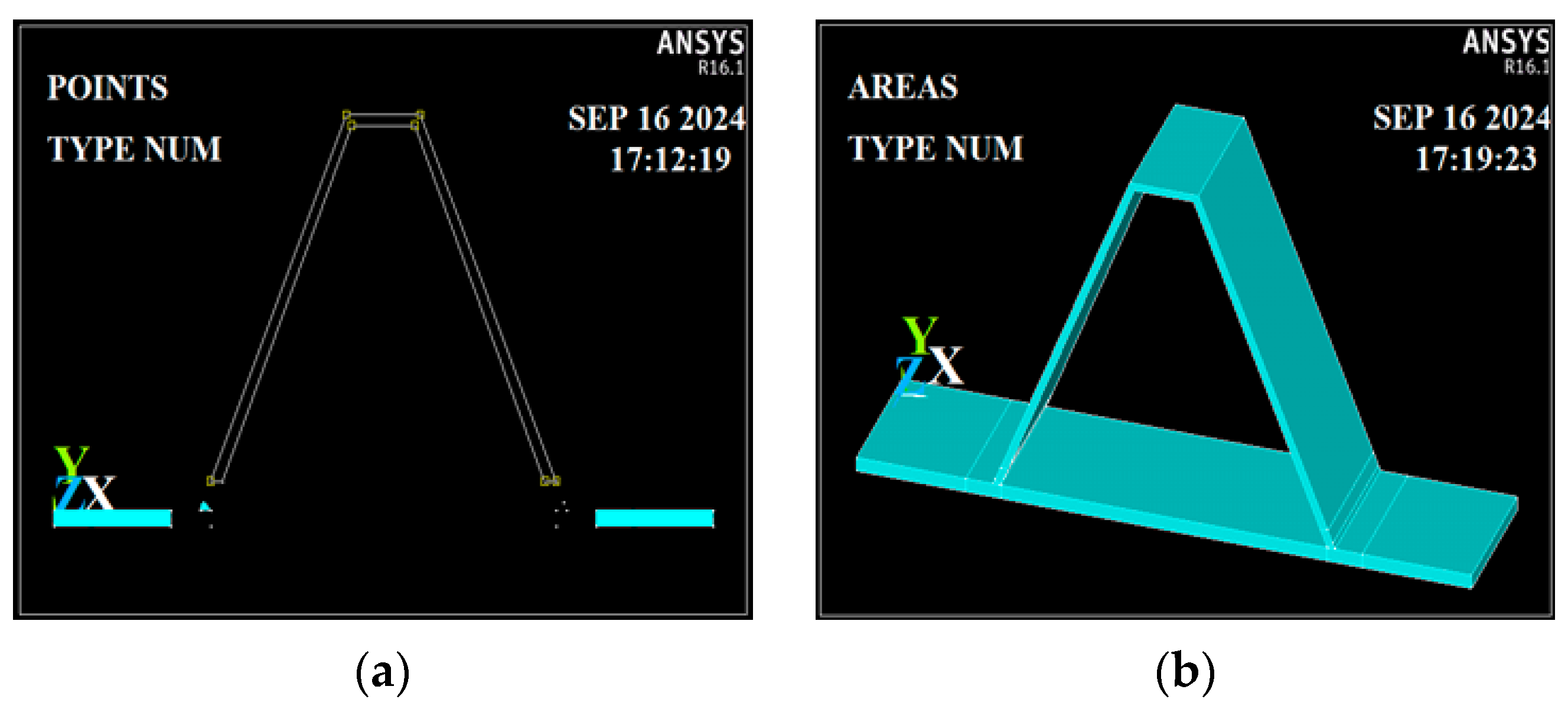
Using the defined key points, areas were created as shown in Figure 6a. These areas were then extruded by 100 mm along the Z-direction, resulting in solid volumes representing the rib plate, deck plate, and butt RDWs, as illustrated in Figure 6b. The volumes were glued together, as the analysis was conducted within the elastic range. This approach was chosen to identify stress distributions and concentration zones prior to yielding, particularly near the RDW root. While the experimental failure criterion corresponds to yielding, the elastic model provides a sufficiently accurate approximation of the mechanical behavior, as confirmed by the close agreement (within 3%) between the experimental and analytical results. We acknowledge that excluding plasticity may slightly affect stress redistribution near yield zones, but for the studied loading range and geometric variations, the elastic assumption remains valid. Failure was defined as the onset of yielding, in accordance with [,,]. Further details are provided in Appendix B.
Figure 6. Composite figure showing (a) the creation of areas for the analytical model; (b) the glued volumes representing the rib plate, deck plate, and RDWs.
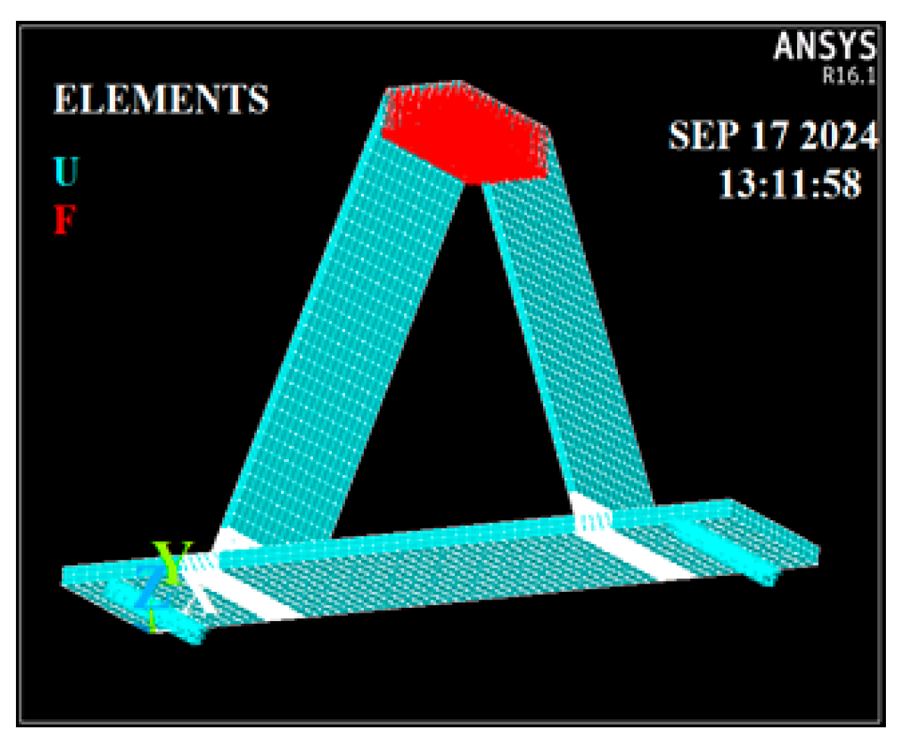
The volumes were meshed using Solid186 elements [], as shown in Figure 7. These are quadratic 20-node elements, which provide higher accuracy in stress and deformation analysis. A mesh size of 8 mm was applied to the plates to ensure sufficient resolution for capturing stress gradients.
Figure 7. The analytical model.
Regions located at a distance of 2 t from the weld toes were meshed with a 0.1 t element size, where (t) is the thickness of the plate containing the RDW toe. For the butt RDWs, a finer mesh size of tr/30 was applied. A mesh sensitivity study was performed to validate these choices, confirming that further refinement resulted in stress variations below 3%. This ensures numerical stability and that the reported results are independent of discretization effects. The model was simply supported over a span of 380 mm, consistent with the experimental setup. A monotonically increasing static compression load (F) was applied to the top of the rib plate, replicating the experimental conditions.
Following calibration with the experimental model, four additional analytical models were developed, each with a different rib plate thickness (tr): 6 mm, 7 mm, 8 mm, and 9 mm. These models were used to investigate the influence of the slenderness ratio (h′/tr) on the stress state in both the rib plate and the RDW root. Fatigue life was estimated using the Nominal Stress Method, where static stress amplitudes obtained from elastic simulations were treated as equivalent cyclic stresses. This approach assumes constant amplitude loading and follows IIW and Eurocode 3 guidelines. No additional scaling or cyclic calibration was applied. The method provides a conservative estimate of fatigue performance and is suitable for comparing RDW root behavior across different h′/tr ratios under elastic stress conditions. In the regression model, the compression force (F) was defined as the independent variable, while the vertical stress (σy)—either tensile or compressive—was treated as the dependent variable.
For each h′/tr value, 60 data points were input, consisting of F values ranging from 5500 N to 31,500 N in increments of 500 N, along with their corresponding σy values. The Enter Method was used for regression analysis. The resulting regression coefficients were evaluated for statistical significance using the T-test, ensuring the reliability of the predictive models. Further details and explanations are provided in Appendix C.

3. Results

3.1. Analytical Results

3.1.1. Comparison Between Analytical and Experimental Results

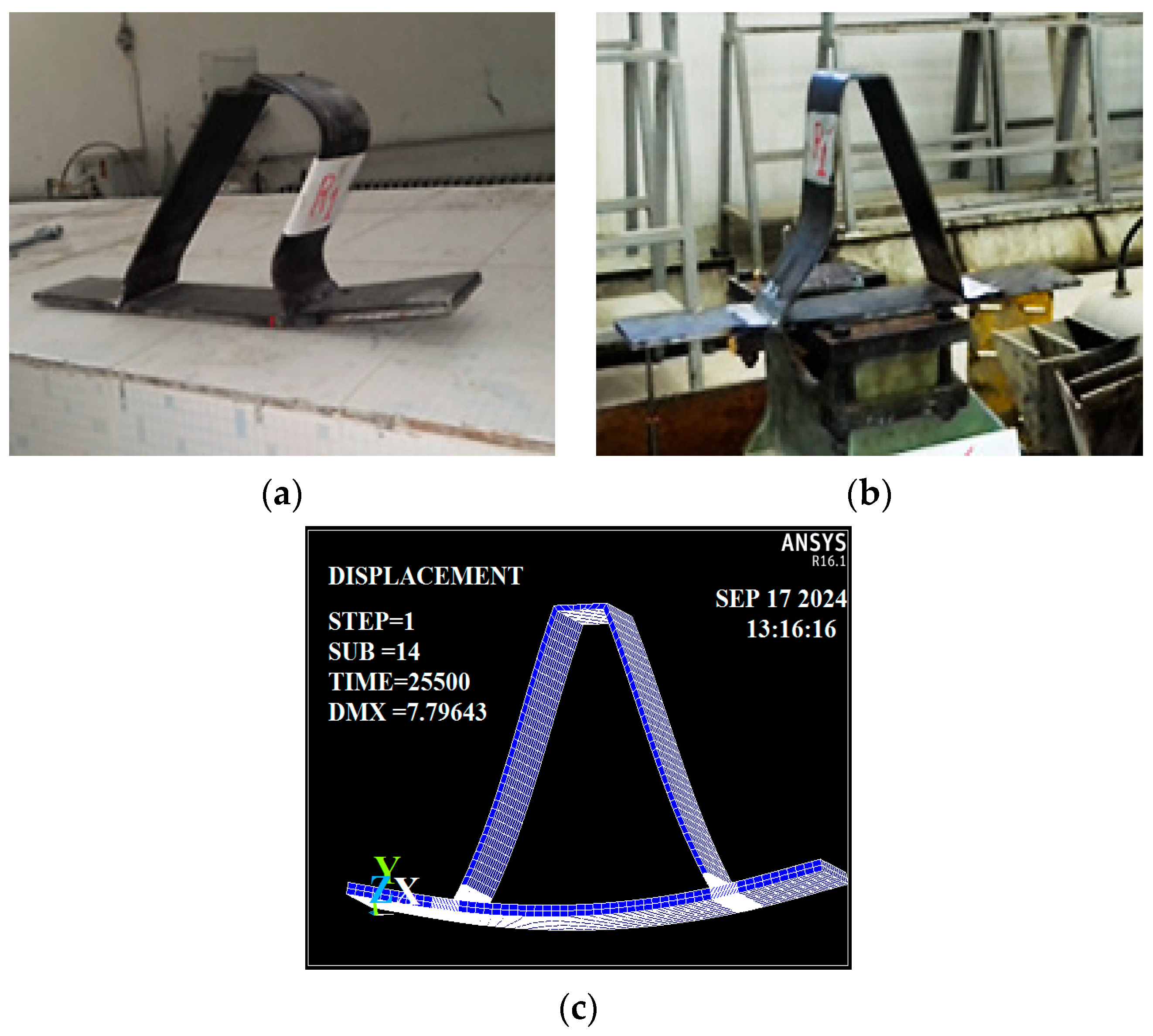
The deformed shapes of both the experimental and analytical models were found to be nearly identical, as illustrated in Figure 8. It can be observed that the compression region is located in the rib plate above the RDW toes, while the tension region is concentrated at the RDW root.
Figure 8. Composite figure showing deformation shapes of the models: (a) experimental model R1; (b) experimental model R’1; and (c) analytical model.
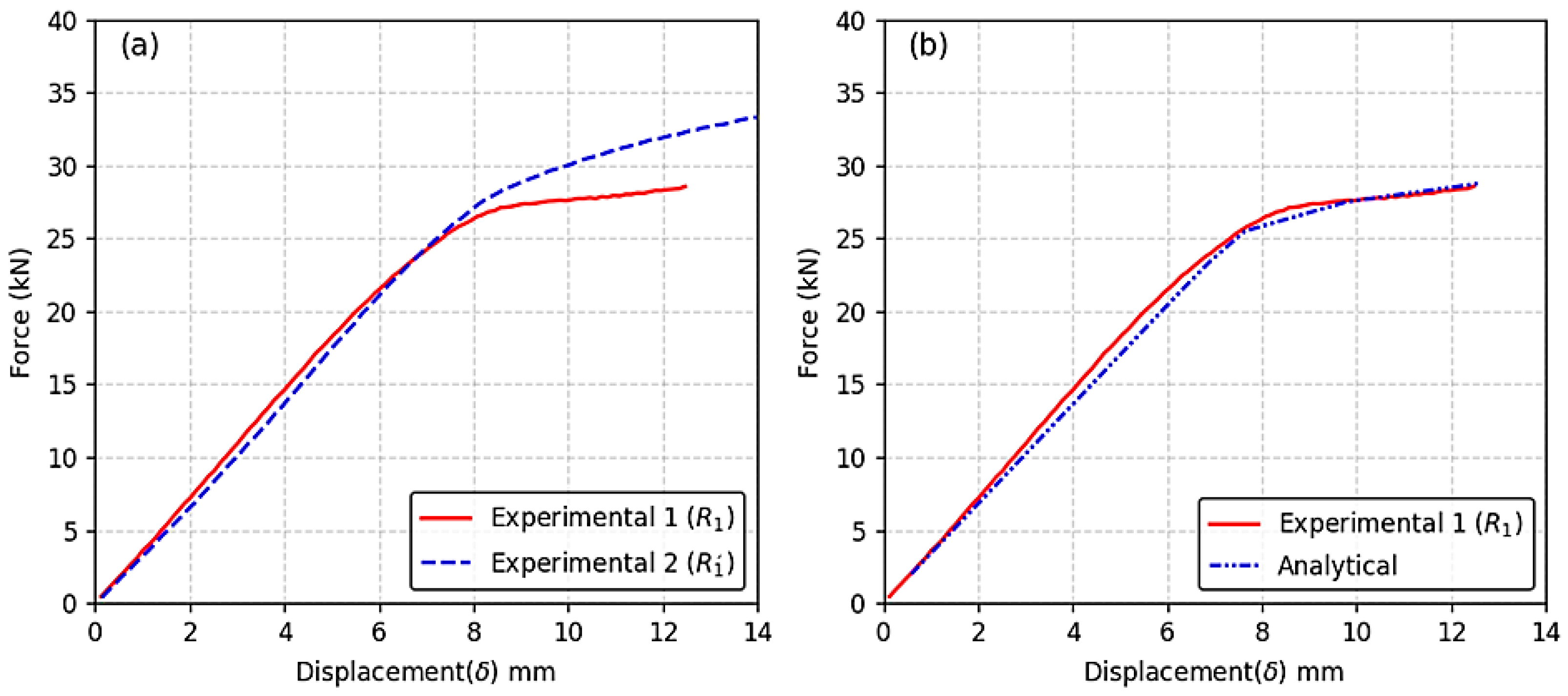
The displacement records obtained from Catman 4.0.3 software were plotted using Excel. The yielding (failure) force of the experimental model was approximately 2.7 tons, as shown in Figure 9a.
Figure 9. Composite figure showing force–displacement behavior: (a) experimental force–displacement curves; (b) comparison between experimental and analytical results.
In comparison, the analytical model exhibited a failure force of approximately 2.6 tons, resulting in a relative difference of 3%, as illustrated in Figure 9b.

3.1.2. Analytical Model Comparison Across Different h′/tr Ratios

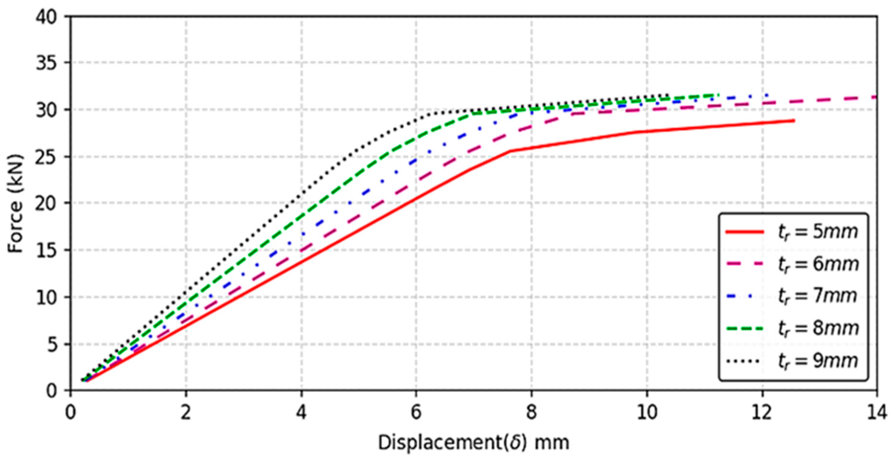
The load–deflection curves presented in Figure 10 demonstrate the influence of the rib’s web thickness, tr, on its mechanical behavior under loading. As tr increases from 5 mm to 8 mm, the rib exhibits greater stiffness and load-bearing capacity, as evidenced by the upward shift and steeper slope of the curves.
Figure 10. Load–deflection (F-δ) curves for the analytical models.
This means that for a given displacement, ribs with thicker webs can sustain higher loads, indicating improved structural performance. The results highlight the critical role of web thickness in enhancing both the strength and rigidity of the rib, which is essential for optimizing design in structural applications. The σy stress contours under an applied load of 25, 5 kN were illustrated in Figure 11.
Figure 11. Stress contours (σy) in the analytical models under an applied load of 25.5 kN: (a) tr = 5 mm, Z = 100 mm; (b) tr = 5 mm, Z = 50 mm; (c) tr = 6 mm, Z = 50 mm; (d) tr = 7 mm, Z = 50 mm; (e) tr = 8 mm, Z = 50 mm; (f) tr = 9 mm, Z = 50 mm.
The σy stress contours across the five models reveal that the maximum compressive stress (σy com) occurs in the rib plate at a distance of 2tr from the RDW toe, while the maximum tensile stress (σy ten) is concentrated at the RDW root, as illustrated in Figure 11a–f. Furthermore, it was observed that increasing the web thickness, tr, reduces the extent of the compression zone and intensifies the concentration of σy ten at the RDW root, indicating a shift in stress distribution with structural thickening.
The σy tensile stress path under a force of F = 25,500 N, starting at the RDW root and extending over a length d = 12 mm, reveals a significant influence of the rib thickness (tr) on stress concentration. As shown in Figure 12, increasing tr leads to a more pronounced peak in σy ten, especially evident when tr = 8 mm, where the stress concentration becomes markedly higher. This behavior is attributed to the reduced deformation capacity of the rib plate, which limits its ability to redistribute stress. When tr = 9 mm, the rib plate section near the RDW root transitions into a more rigid, stress-resistant zone. Consequently, the tensile stress σy ten becomes less concentrated, resulting in a lower peak compared to tr = 8 mm. This suggests that beyond a certain thickness, the plate’s ability to absorb and redistribute stress diminishes, leading to a more uniform stress distribution.
Figure 12. The tension stresses in the RDW root—F = 25,500 N.
The h′/tr ratio, where h′ represents the inclined rib length and tr its thickness, plays a crucial role in determining the mechanical behavior under applied loads. According to Equation (1), which sets a limit value of 38 for this ratio based on geometric parameters—b being the central base of the trapezoidal rib and td the deck thickness []—the ratio governs the balance between compressive and tensile stress fields:
h / t r   b 3 t d 3   ×   400
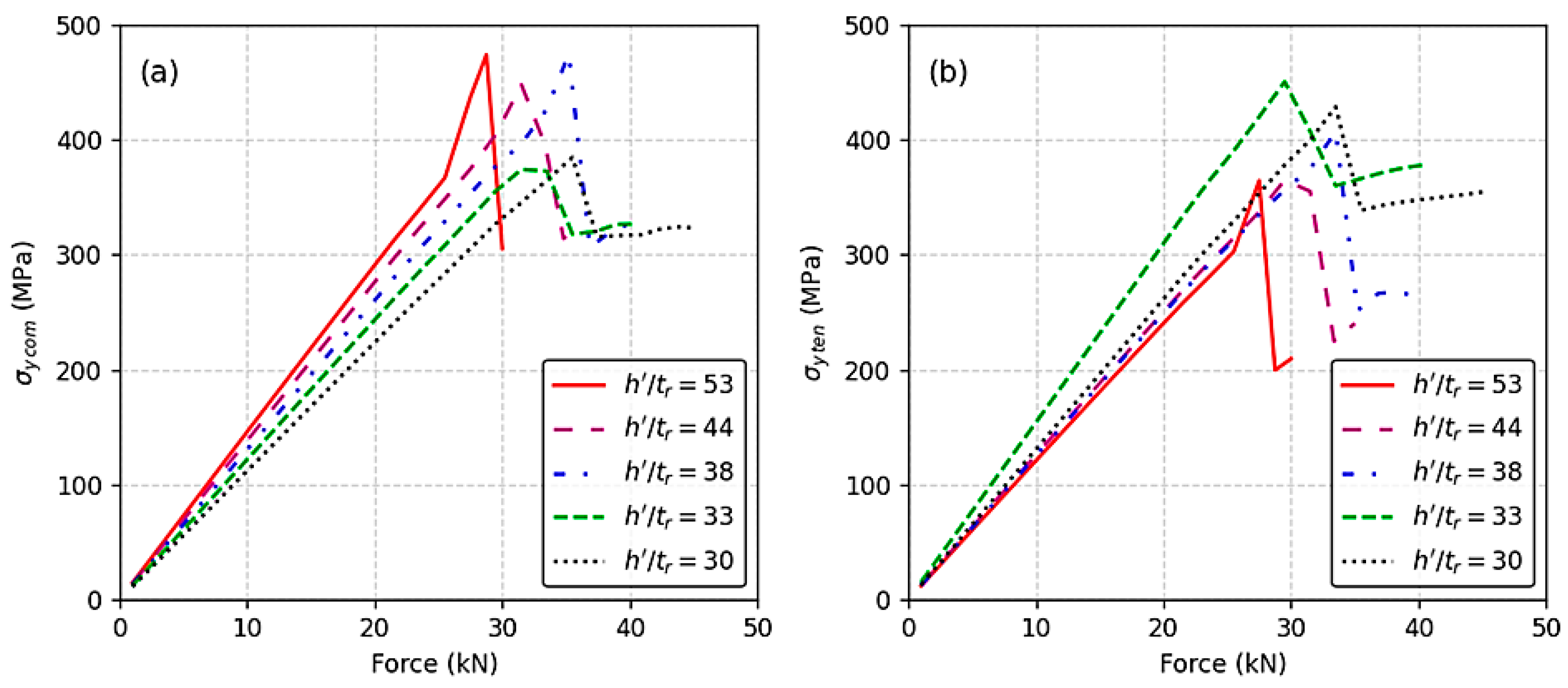
Figure 13a illustrates the effect of varying h′/tr ratios on the σy compression field within the rib plate. As the h′/tr ratio decreases from 53 to 30, the maximum compressive stress σy com also decreases. This trend indicates that lower h′/tr ratios promote a broader elastic compression field, allowing the rib plate to deform more uniformly and absorb compressive loads more effectively. This behavior is beneficial in preventing localized stress concentrations that could lead to premature failure.
Figure 13. Effect of applied compression force on vertical stress σy in the rib plate and RDW root: (a) maximum compressive stress σy com in the rib plate; (b) maximum tensile stress σy ten in the RDW root.
In contrast, Figure 13b shows the corresponding effect on the σy tension field at the RDW root. Generally, decreasing the h′/tr ratio increases the tensile stress σy ten, suggesting a more concentrated stress field. However, an interesting deviation occurs when the ratio drops from 33 to 30: instead of increasing, σy ten slightly decreases. This suggests a shift toward a more elastic tension response, possibly due to geometric constraints or redistribution of stress paths.
Together, these findings highlight the dual influence of the h′/tr ratio. While lower ratios enhance the elastic compression behavior of the rib plate, they also affect the tensile stress concentration at the RDW root. Optimizing this ratio is therefore crucial for achieving balanced mechanical performance and enhancing structural resilience.
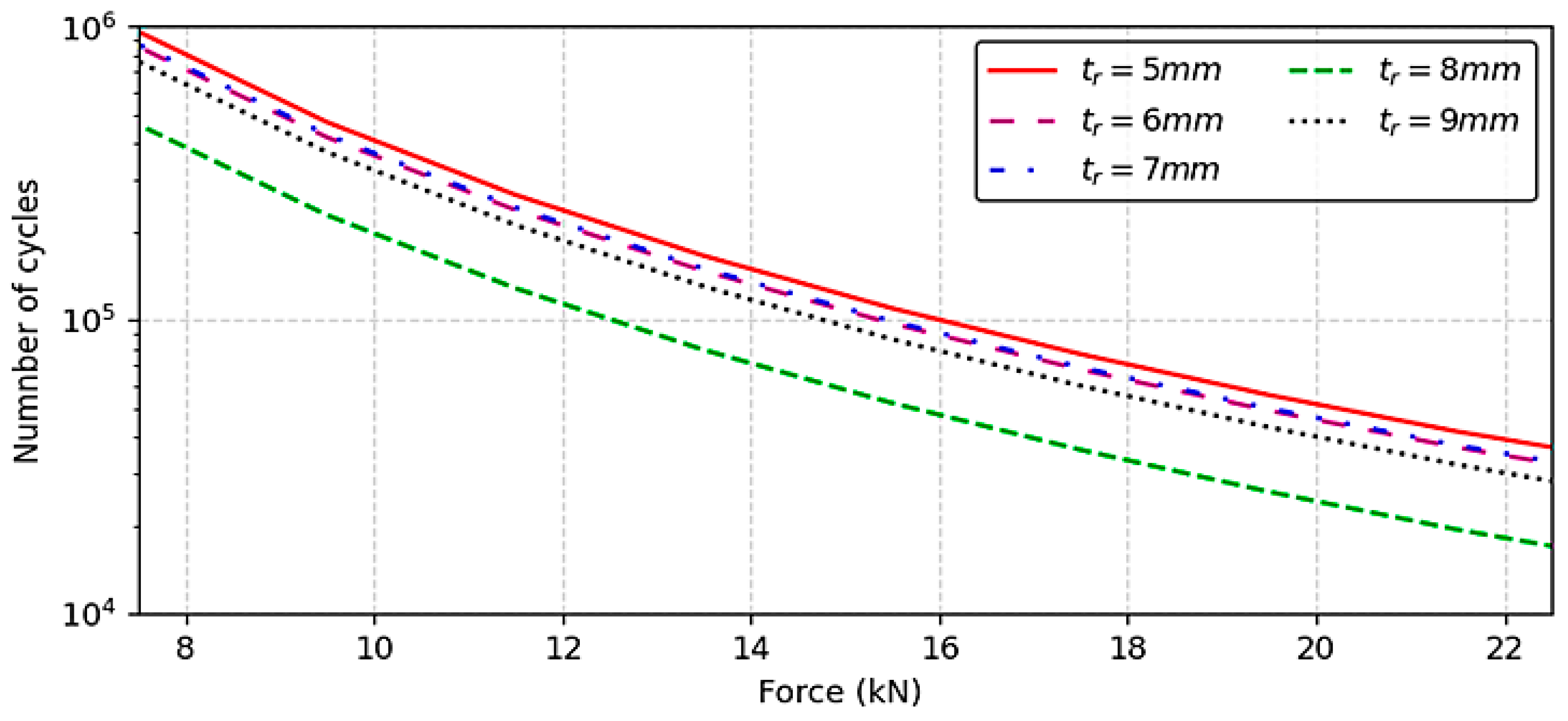
The number of load cycles (N) at the RDW root was calculated using the Nominal Stresses Method, as outlined in the IIW guidelines (Equation (2)), as referenced in [,] and also adopted in Eurocode 3 []. The results indicate that increasing the h′/tr ratio enhances the fatigue performance of the RDW root by increasing the number of cycles to failure (N), as illustrated in Figure 14 and Table 2. In this context,
Figure 14. Number of load cycles in the RDW root.
Table 2. The relative difference for N in the RDW root due to the effect of F = 7500 N.
  • FAT is the fatigue strength corresponding to 2 million cycles (2 × 10⁶), defined by IIW as 71 MPa.
  • m is the slope of the S-N curve, taken as 3 for bending stress conditions.
  • S is the applied alternating fatigue stress, which is the same as the elastic stress obtained from static analysis [,].
The fatigue life (N) is evaluated using the following equation:
N   =   2,000,000   ×   (   FAT S   ) m ,
This equation reflects the weld’s performance in terms of the number of load cycles it can withstand before failure.
From Table 2, it can also be noticed that the relative difference in N between h′/tr = 38 (the limit value) and h′/tr = 33 equals to 47%, which means that using h′/tr values that are less than the limit value decreases RDW root performance to almost half.

3.1.3. Comparison of Maximum Compressive Stress in the Rib Plate (σy com) and Maximum Tensile Stress in the RDW Root (σy ten) for Various h′/tr Ratios

The influence of the h′/tr ratio on stress distribution and failure mode in welded joints is clearly illustrated in Figure 15a–e. These figures compare the maximum compressive stress (σy com) in the rib plate with the maximum tensile stress (σy ten) in the RDW root across a range of h′/tr values.
Figure 15. Stress distribution comparison between compressive stress in the rib plate (σy com) and tensile stress in the RDW root (σy ten) for various h′/tr ratios: (a) h′/tr = 53; (b) h′/tr = 44; (c) h′/tr = 38; (d) h′/tr = 33; (e) h′/tr = 30.
When h′/tr exceeds the limit value of 38, as shown in Figure 15a (h′/tr = 53) and Figure 15b (h′/tr = 44), the compressive stress in the rib plate becomes dominant, exceeding the tensile stress in the RDW root. In these cases, the structural response is governed by the compressive behavior of the rib plate, and yielding (or failure) is primarily due to σy com.
At the limit value of h′/tr = 38 (Figure 15c), the compressive and tensile stresses are nearly equal. This balance indicates that both the rib plate and RDW root operate within a similar elastic stress field, with no clear dominance of one stress type over the other. This configuration represents a transitional state where the structural performance is optimized, and neither component is disproportionately stressed.
When h′/tr falls below the limit, as seen in Figure 15d (h′/tr = 33) and Figure 15e (h′/tr = 30), the tensile stress in the RDW root surpasses the compressive stress in the rib plate. In these cases, the RDW root becomes the critical zone, and failure is driven by σy ten. This shift highlights the reduced fatigue performance and increased vulnerability of the RDW root when the h′/tr ratio is too low. These observations emphasize the importance of maintaining an optimal h′/tr ratio to ensure balanced stress distribution and improved fatigue resistance in welded structural components.

3.2. Statistical Results

The results of the multiple linear regression (MLR) analysis are summarized in Table 3, where the derived equations provide predictive models for stress behavior in welded joints. These models were statistically validated using the T-test, confirming their high significance. The adjusted R2 value for all models was equal to 1, indicating a perfect fit and suggesting that the MLR equations offer highly accurate predictions of stress responses [].
Table 3. MLR concluded equations.
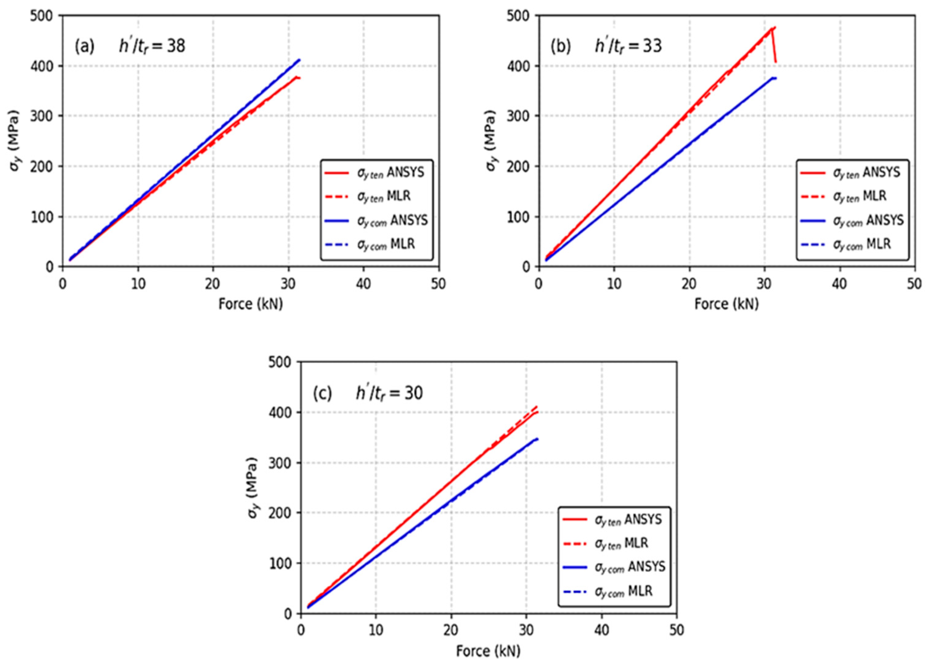
It should be noted that the MLR equations derived in this study are specific to models with full-penetration butt welds, where the weld thickness equals the thickness of the material, tr. These results may not directly apply to other weld types. Future studies are recommended to extend this analysis to filet and hybrid welds. To further validate the reliability of these models, Figure 16a–c present a comparative analysis between the stress values predicted by the MLR equations and those obtained from ANSYS 16.1 simulations.
Figure 16. Comparison between stress predictions from multiple linear regression (MLR) equations and ANSYS 16.1 simulations for various h′/tr ratios: (a) h′/tr = 38; (b) h′/tr = 33; (c) h′/tr = 30.
These figures illustrate the variation of σy ten in the RDW root and σy com in the rib plate across different h′/tr ratios under increasing force. The comparison reveals that the relative differences between the MLR predictions and ANSYS results do not exceed 3%, demonstrating excellent agreement between the analytical and numerical approaches.
This close correlation confirms that the MLR equations are not only statistically robust but also practically reliable for predicting stress distributions in welded structures. Specifically, they enable accurate estimation of both tensile stress in the RDW root and compressive stress in the rib plate, which are critical for assessing structural integrity and fatigue performance. By using these equations, engineers can efficiently evaluate the stress state in welded joints without relying solely on time-consuming finite element simulations. This contributes to faster design iterations and improved decision-making in structural optimization, especially when assessing the impact of geometric parameters such as the h′/tr ratio.

4. Discussion

When a compressive force is applied to the rib plate—similar to the stress state in the negative bending region of an orthotropic steel deck—it was observed from both the experimental and analytical models in this study that the compressive stress region is located in the rib plate above the toes of the rib-to-deck welds (RDWs). Conversely, the tensile stress region is concentrated in the root of the RDW. These stress distributions were clearly identified through the deformation shapes obtained from the models.
This study confirmed the inverse relationship between the geometric ratio h′/tr and the location of yielding. When the value of h′/tr exceeds a certain threshold, the maximum compressive stress σy com in the rib plate becomes greater than the maximum tensile stress σy ten in the RDW root. In this case, yielding—and thus failure—is governed by σy com, which is attributed to the higher deformation capacity of the rib plate. These findings warrant a re-examination of previous studies [,,,,], which have primarily focused on RDW performance using plate models with fixed dimensions. The observed stress patterns suggest that symmetric geometric configurations, particularly those with balanced h′/tr ratios, contribute to uniform stress distribution. This symmetry enhances fatigue resistance and structural resilience by minimizing localized stress concentrations. Future research could build upon those studies, integrating the present results to refine the understanding of RDW behavior under varying geometric configurations.
When h′/tr reaches the threshold value, the maximum compressive stress in the rib plate and the maximum tensile stress in the RDW root are nearly equal. This indicates that both regions operate within a similar elastic field. Conversely, when h′/tr falls below the threshold, the maximum tensile stress σy ten in the RDW root exceeds the compressive stress in the rib plate. In this scenario, yielding is governed by σy ten, and failure initiates at the RDW root. This observation supports and reinforces the findings of Li et al. [], which demonstrated that the interior weld toe of the U-rib-to-top plate joint within the diaphragm zone is the region most susceptible to fatigue. Similarly, Zhang et al. [] reported field observations of fatigue cracks originating from the RDW root. It is essential to note that neither of the two studies [,] accounted for geometric variations or slenderness criteria, which may significantly influence stress distribution and failure mechanisms.
This study demonstrated the inverse relationship between the geometric ratio h′/tr and the performance of the RDW root. When the h′/tr ratio falls below the threshold value, the performance of the RDW root decreases significantly—by nearly half—compared to the initial condition. This reduction is attributed to the diminished deformation capacity of the rib plate, which causes stress to concentrate more intensely in the RDW root.
For values of h′/tr slightly below the threshold, the maximum tensile stress σy ten in the RDW root may be somewhat reduced due to the increased resistance of the plate section in the RDW root region. However, σy ten still exceeds the maximum compressive stress σy com in the rib plate, indicating that failure is governed by tensile stress in the RDW root.
The multiple linear regression (MLR) equations presented in Table 3, developed specifically for the trapezoidal rib–deck section studied here, are effective for predicting both σy com and σy ten. These equations enable the identification of the stress state in the rib plate and RDW root for each acceptable h′/tr value, thereby allowing assessment of RDW performance. As such, they can serve as a comparative standard across different models.
Residual stresses and heat-affected zone (HAZ) effects are known to influence fatigue performance, especially under tensile loading. In this study, the rib–deck section was subjected to compression loads in the rib plate, simulating the stress state in the cross-region with the floor beam. Since the RDW root was not directly exposed to tensile fatigue loading, residual stress and HAZ effects were not considered. Their omission may lead to higher stress concentrations in the RDW root, and this limitation will be acknowledged in future research.
The h′/tr ratio physically represents the slenderness of the inclined rib web. A higher ratio indicates a slenderer rib, which is more flexible and capable of distributing compressive stresses over a wider area. This results in dominant compressive behavior in the rib plate. Conversely, a lower h′/tr ratio corresponds to a stiffer rib section, which restricts deformation and causes stress concentration at the RDW root. This shift increases tensile stress and reduces fatigue resistance. Therefore, h′/tr governs the balance between structural flexibility and stress localization, making it a crucial parameter in welded joint performance.
For future research, it is recommended to re-examine trapezoidal rib–deck sections with varying dimensions to assess their influence on the stress distribution in the rib plate and RDW root. Additionally, studies should explore alternative closed rib geometries, such as U-shaped or V-shaped ribs, and investigate the use of different weld types, such as filet welds.

5. Conclusions

This study investigated the intricate relationship between the elastic–plastic behavior of the rib plate and the fatigue performance of the rib-to-deck weld (RDW) root in orthotropic steel bridge decks. Through a combined experimental and analytical approach, the following key conclusions were drawn:
  • Stress Distribution: under compressive loading simulating the negative bending moment region, maximum compressive stress (σy com) concentrates in the rib plate above the weld toes. In contrast, maximum tensile stress (σy ten) localizes at the critical RDW root.
  • Critical Role of h′/tr Ratio: the geometric slenderness ratio h′/tr is a pivotal parameter governing the failure mode and fatigue life.
    • When h′/tr exceeds the limit value of 38, compressive stress in the rib plate dominates, and failure is governed by the rib plate yield.
    • At the limit value of h′/tr = 38, a balanced state is achieved where compressive and tensile stresses are nearly equal, optimizing structural performance.
    • When h′/tr falls below the limit, tensile stress at the RDW root becomes dominant, leading to a significant reduction in fatigue performance. A decrease from h′/tr = 38 to 33 resulted in a 47% drop in the number of load cycles to failure.
  • Symmetry and Structural Performance: the observed stress patterns suggest that symmetric geometric configurations, particularly those with balanced h′/tr ratios, contribute to uniform stress distribution. This symmetry enhances fatigue resistance and structural resilience by minimizing localized stress concentrations. The trapezoidal rib geometry, with its bilateral symmetry, plays a key role in balancing stress fields across the weld and plate.
  • Predictive Modeling: the developed multiple linear regression (MLR) equations provide a highly accurate and practical tool for predicting stress values in both the rib plate and the RDW root, eliminating the need for extensive finite element simulations in preliminary design stages.
However, this study is subject to certain limitations. The analysis was confined to static loading and an elastic material model, which was used to identify stress concentration zones; the effects of low-cycle fatigue and plastic stress redistribution were not captured. Furthermore, the influence of welding-induced residual stresses and the microstructural properties of the heat-affected zone (HAZ), which are known to impact fatigue crack initiation significantly, was not considered. The simplified supported boundary condition and the focus on a single trapezoidal rib geometry with full-penetration butt welds also define the scope of the current findings.
Despite these limitations, the results unequivocally demonstrate that optimizing the h′/tr ratio is essential for achieving a balanced stress distribution and enhancing the fatigue resistance of orthotropic steel bridge decks. The findings provide designers with clear guidance for selecting rib plate geometries to improve the resilience of these critical connections. Future work should address the present limitations by incorporating cyclic plasticity and residual stresses, and extending the analysis to other rib geometries and weld types to generalize these findings further.

Author Contributions

Conceptualization, H.A. and A.Q.M.; methodology, G.W.; software, H.A.; validation, H.A., A.Q.M. and G.W.; formal analysis, H.A.; investigation, H.A. and A.Q.M.; resources, H.A. and G.W.; data curation, H.A.; writing—original draft preparation, H.A.; writing—review and editing, H.A., A.Q.M. and G.W.; visualization, H.A. and G.W.; supervision, A.Q.M.; project administration, G.W.; funding acquisition, H.A. All authors have read and agreed to the published version of the manuscript.

Funding

This research received no external funding.

Data Availability Statement

The raw data supporting the conclusions of this article will be made available by the authors upon request.

Conflicts of Interest

The authors declare that they have no conflicts of interest.

Abbreviations

The following abbreviations are used in this manuscript:
OSDOrthotropic Steel Deck
RDWRib-to-deck welds
fyYielding stress
fuBreak stress
E6013Electrode with 60 ksi yielding stress (410 MPa); 1 presents that it can use all directions, 3 presents a more power cover material
tdThickness of the deck plate
LLength of the deck plate
wWidth of the deck plate
trThickness of the rib plate
hTrapezoid rib height
bTrapezoid rib major base
aTrapezoid rib minor base
θThe inner angle between the rib and deck
h′The inclined portion length of the trapezoid rib web
NNumber of load cycles
FApplied compression force
EYoung’s modulus
υPoisson’s ratio
δThe total displacement
σyBending stresses by y-axis direction
σy comThe maximum compression stress in the rib plate
σy tenThe maximum tension stress in the rib-to-deck weld root
dStresses path
IIWInternational Institute of Welding
FatFatigue stress
SApplied fatigue stress
mTangent of fatigue stress—number of load line
∆%Relative difference
h′/trThe local buckling standard of the rib plate
MLRMultiple linear regression
SPSSStatistical Package for Social Science
R2-AdjustedExplaining strength factor

Appendix A

The model studied in this research is a full-scale rib–deck section. This section has been considered the most suitable since Maddox began investigating rib-to-deck welds (RDWs) in 1974. The rib–deck configuration allows for the examination of all potential failure modes in RDWs—whether due to bending or shear—as transverse stresses are predominant []. Moreover, analyzing multiple sections and conducting a statistical study can be highly beneficial for addressing complex problems.
In contrast, an Orthotropic Steel Deck (OSD) model is inadequate for RDW investigations. It fails to provide a clear understanding of the stress state and failure mechanisms specific to RDWs. However, the OSD model can be useful for studying welds between rib plates and floor beams, or between floor beams and main girders [,].

Appendix B

In the analytical model, the volumes were glued together, as the study is confined to the elastic domain. Failure is defined by the onset of yielding, consistent with previous studies that included weld modeling. Another fundamental reason for gluing the volumes is the nature of the weld material itself.
Typically, the weld metal is a type of steel with a yield stress higher than that of the surrounding steel plates. Both materials have an elastic modulus of approximately 200,000 MPa, with negligible differences that do not significantly affect the results.
In practice, the welding process involves melting both the electrode and small portions of the steel plates in the connection region. These materials mix and solidify to form a homogeneous welded surface. Therefore, an isolated interface between the weld and the plates is not present, as Figure A1 [].
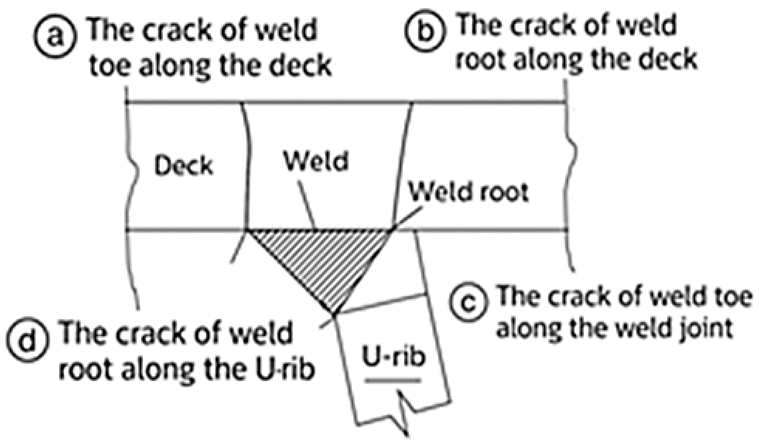
This phenomenon has been confirmed by numerous studies and references, which consistently show that failure does not occur at the weld–plate interface [,]. Instead, fatigue cracks typically propagate along the weld and into the body of the plates, as Figure A2 [].
Figure A1. (a) The weld region in previous research []; (b) the weld region in this research.
Figure A2. Fatigue cracks in RDW.

Appendix C

Multiple linear regression analysis is one of the most important statistical methods for analyzing relationships between variables. It is particularly useful for predicting the value of a quantitative dependent variable based on the influence of several quantitative independent variables. This relationship is expressed through a mathematical model, as shown in Equation (A1) []:
y = β0 + β1x1 + β2x2 + … + βpxp + e,
where y is the dependent variable, β0 is the intersection point with y axis, βi (i=1…p) are regression coefficients, xi (i=1…p) are the independent variables. e is the random mistake. Multiple linear regression assumes that the data follow a normal distribution. To ensure statistical validity, the sample size should not be less than thirty for both the independent and dependent variables. The regression coefficients can be determined using multiple linear regression analysis with software such as SPSS. A t-test can be performed to assess the statistical significance of each regression coefficient.
The explanatory power of the regression model is evaluated using the adjusted R2 value. When the adjusted R2 equals 1, the regression equation perfectly predicts the dependent variable, meaning that the independent variables account for all variations in values such as σy com and σy ten. For example, an adjusted R2 of 0.90 indicates that 90% of the variation in these stress values is explained by the model.
In this research, multiple linear regression analysis was employed to derive predictive equations linking the weld root stress to the geometric ratio h′/tr, under an applied compressive force F. These equations can serve as a comparative standard across different rib–deck sections by identifying the maximum compressive stress σy com in the rib plate and the maximum tensile stress σy ten in the RDW root. Figure A3 illustrates the steps of the MLR analysis for the predictive equation of σy com when tr = 8 mm, as presented in Table 3.
Figure A3. MLR analysis steps for σy com predictive equation when tr = 8 mm.

References

  1. Connor, R.; Fisher, J.; Gatti, W.; Gopalaratnam, V.; Kozy, B.; Leshko, B.; Quaid, D.; Medlock, R.; Mertz, D.; Murphy, T.; et al. Manual for Design Construction and Maintenance of Orthotropic Steel Deck Bridge, 1st ed.; Federal Highway Administration: Washington, DC, USA, 2012. [Google Scholar]
  2. Hartmann, J. Guide for Orthotropic Steel Deck Level 1 Design, 1st ed.; Federal Highway Administration: Washington, DC, USA, 2022. [Google Scholar]
  3. Chou, C.C.; Uang, C.M.; Seible, F. Experimental evaluation of compressive behavior of orthotropic steel plates for the new San Francisco–Oakland bay bridge. Bridge Eng. 2006, 11, 140–150. [Google Scholar] [CrossRef]
  4. Yuan, H. Optimization of Rib-to-Deck Welds for Steel Orthotropic Bridge Decks. Master’s Thesis, State University, Petersburg, VA, USA, November 2011. [Google Scholar]
  5. Zhang, Q.; Yizhi, B.U.; Qiao, L.I. Review on Fatigue Problems of Orthotropic Steel Bridge Deck. China J. Highw. Transp. 2017, 3, 14–39. [Google Scholar]
  6. Waele, S.D. Stress Concentration Effects Due to Weld Root Imperfections in Orthotropic Steel Decks. Master’s Thesis, Ghent University, Ghent, Belgium, June 2017. [Google Scholar]
  7. Akad, H. Studying Performance of Rip-to-Deck Weld (RDW) in Orthotropic Steel Decks of Highway Steel Bridges Analytically and Experimentally. Doctorate Thesis, Aleppo University, Aleppo, Syria, July 2024. [Google Scholar]
  8. Li, X.; Lin, H.; Zhao, A.; Wang, R.; Feng, Z.; Zhang, S.; Wu, B.; Wu, C.; Xu, X. Experimental study on fatigue performance of double welded orthotropic steel bridge deck. J. Constr. Steel Res. 2024, 213, 108418. [Google Scholar] [CrossRef]
  9. Wang, D.; Shi, J.; Tan, B.; Shao, Y. Effect of pavement layer temperature on fatigue performance of rib-to-deck weld details in orthotropic steel bridge decks. Constr. Build. Mater. 2024, 452, 138919. [Google Scholar] [CrossRef]
  10. Chen, F.; Liu, Q.; Lu, Y.; Luo, Y.; Xiao, X.; Liu, Y.; Chen, B.; Zhang, H.; Chen, Y. Fatigue reliability assessment of rib-to-deck double-sided welded joints in orthotropic steel decks considering welding residual stress. Sci. Rep. 2024, 14, 31418. [Google Scholar] [CrossRef] [PubMed]
  11. Gao, B.W.; Jiang, X.; Lv, Z.L.; Qiang, X.H. Experimental study on fatigue properties of rip-to-deck welds repaired by angle steel. Proceedings of the 6th International Conference on Smart Monitoring. Assess. Rehabil. Civ. Struct. 2024, 259, 441–450. [Google Scholar]
  12. Pei, J.; Wang, X.; Qin, S.; Xu, G.; Su, F.; Wang, S.; Li, Z. Experimental and numerical simulation study on residual stress of single-side full-penetration welded rip-to-deck joint of orthotropic steel bridge deck. Buildings 2024, 14, 2641. [Google Scholar] [CrossRef]
  13. Gao, Y.; Ji, B.; Zhou, Y.; Fu, Z.; Wang, Q. Study on the fatigue performance of rewelding rib-to-deck weld root cracks from the deck surface. Int. J. Steel Struct. 2025, 25, 1168–1177. [Google Scholar] [CrossRef]
  14. Thakre, A.M.; Bora, A.; Podder, D. Influence of residual stresses on the fatigue behavior of an orthotropic steel deck using fracture mechanics approach. Int. J. Steel Struct. 2025, 25, 773–783. [Google Scholar] [CrossRef]
  15. Worku, Z.; Liu, M.; Wang, X.; Sheng, G. Flexural behavior of orthotropic steel–LUHPC composite bridge decks: Experimental and numerical study. Mech. Mater. 2025, 18, 2106. [Google Scholar] [CrossRef] [PubMed]
  16. Abdelbaset, H.; Zhu, Z.; Pyram, M. Buckling behavior of closed-ribs orthotropic steel decks in long-span suspension bridges. Alexandaia Eng. J. 2025, 117, 260–275. [Google Scholar] [CrossRef]
  17. Villoria, B.; Siriwardane, S.; Jakobsen, J. Fatigue assessment of rip-to-deck welded joints in orthotropic steel bridge decks under traffic loading. CivilEng 2025, 6, 7. [Google Scholar] [CrossRef]
  18. Medlock, R.; Gilmer, H.; Miller, D.; Ream, A. Bridge Welding Reference Manual, 1st ed.; Federal Highway Administration: Washington, DC, USA, 2019.
  19. Siemer. Welding Instruction Design. BN 10.050, Index 08; Broetje-Automation Company: Elk Grove Village, IL, USA, 2021. [Google Scholar]
  20. Seffo, M.; Hussein, M. Ansys Software in Civil Engineering Aleppo University, 1st ed.; Faculty of Civil Engineering, Aleppo University: Aleppo, Syria, 2017. [Google Scholar]
  21. Mangus, A.R.; Sun, S. Orthotropic Deck Bridges; CRC Press: Boca Raton, FL, USA, 2000; p. 31. [Google Scholar]
  22. Hobbacher, A. Recommendations for Fatigue Design of Welded Joint and Components; International Institute of Welding: Paris, France, 2008. [Google Scholar]
  23. Barsoum, Z. Guidelines for Fatigue and Static Analysis of Welded and Un-Welded Steel Structures; KTH Royal Institute of Technology: Stockholm, Sweden, 2020. [Google Scholar]
  24. EN 1993-1-9:2005; Eurocode 3: Design of steel structures, Part 1-9: Fatigue. European Committee for Standardization: London, UK, 2005.
  25. El Gimati, Y. Advanced in Statistical Analysis Using SPSS, 1st ed.; University of Benghazi: Benghazi, Libya, 2017; pp. 138–145. [Google Scholar]
  26. Onabi, A. Design of Metal Parts Used in Water Constructions, 1st ed.; University of Aleppo: Aleppo, Syria, 2018; pp. 129–133. [Google Scholar]
  27. Yang, H.; Wang, P.; Qian, H.; Niu, S.; Dong, P. A study fatigue crack propagation paths at U-rip welds in orthotropic bridge decks using a phased –array imaging technique. Theor. Appl. Fract. Mech. 2022, 119, 103310. [Google Scholar] [CrossRef]
  28. Cui, C.; Ma, Y.; Zhang, Q.; Da, L.; Han, S. Fatigue strength and crack growth of double-side welded rip-to-deck joint in orthotropic steel decks. J. Constr. Steel Res. 2022, 196, 107444. [Google Scholar] [CrossRef]
  29. Amritraj, R.; Mishra, S. Fatigue performance of rip-to-deck double-sided weld joint of orthotropic steel deck on plate girder railway bridges. Etasr 2023, 13, 11146–11152. [Google Scholar]
Disclaimer/Publisher’s Note: The statements, opinions and data contained in all publications are solely those of the individual author(s) and contributor(s) and not of MDPI and/or the editor(s). MDPI and/or the editor(s) disclaim responsibility for any injury to people or property resulting from any ideas, methods, instructions or products referred to in the content.

Article Metrics

Citations

Article Access Statistics

Article metric data becomes available approximately 24 hours after publication online.