1. Introduction
In the dynamic landscape of Industry 4.0, smart farming applications confront challenges that are similar to those of cyber–physical systems (CPS) in manufacturing. Central to these challenges is the harmonious integration of technology components such as sensors, actuators, Internet-of-Things (IoT) devices, and in parts the application of big data analytics. The complexity of these challenges reflects a symmetry to the complexities inherent in the software of a cyber–physical system, where seamless interaction between the physical and digital domains is crucial. This paper builds upon a preceding study, concentrating on SilageControl, a smart farming application innovated by the Germany-based enterprise Silolytics [
1].
Advanced technologies in smart farming are set to redefine agricultural production, driving it towards greater efficiency and sustainability [
2]. As smart farming evolves, becoming more integrated and data-driven, the embedded software must equally advance, reflecting a parallel growth in sophistication and capability. Advanced simulation tools have become a key technology, allowing for engineers to create accurate virtual models of machinery, which reflect their real-world counterparts even before physical construction.
This escalation in sophistication brings about a heightened demand for skilled engineers. In 2011, the German National Academy of Science and Engineering (acatech) [
3] reported the shortage of qualified engineers, a need that has only grown since then. Unlike larger software companies that often utilize distributed teams for software development [
4], this model is less prevalent in small and medium-sized enterprises (SMEs), particularly in the field of embedded software systems. In SMEs, embedded software is frequently developed by the same engineers who are responsible for the electrical and/or mechanical components, demonstrating a convergence of skills and roles [
3]. The complexity inherent in CPS underscores the necessity for collaborative efforts that merge mechanical, electrical, and software engineering disciplines. This multi-faceted approach is crucial for handling the complex nature of these systems [
3].
With the increasing demand for context-aware, autonomous, and adaptive robotic systems [
5], there arises a stringent necessity for the embedded software community to embrace more advanced software engineering methodologies. As a result, the way we develop these systems must advance. Achieving this pivotal role necessitates a paradigm shift from reliance on expert-centric tools [
5] to the adoption of modular systems. Such systems are designed to be more accessible and adaptable, enabling domain experts to make effective contributions across various segments of the system.
In recent decades, cost-efficient methodologies such as model-in-the-loop (MIL), software-in-the-loop (SIL), and hardware-in-the-loop (HIL) have become integral to the development process of embedded software systems [
6]. These approaches allow for engineers to bypass certain manual steps using software test beds for simulation and emulation. While simulation and emulation significantly reduce software development costs, the application of HIL is crucial for validating and verifying systems that involve sensors and actuators [
7]. To augment this process and enhance development efficiency, we introduced the concept of the digital twin prototype (DTP) and demonstrated a proof of concept in the Baltic Sea [
8]. In this paper, we emphasize how a digital twin prototype not only enables automated integration testing of embedded software systems without requiring a physical hardware connection, but also serves as a stand-in for the physical system during the development phase of a smart farming application. This introduces a symmetry between the digital twin prototype and the physical system; the DTP mirrors and emulates the functionality and behavior of the physical system, creating a parallel development environment that allows for replicating real-world scenarios in a virtual realm.
This paper is organized in the following manner:
Section 2 introduces the digital twin prototype approach. This approach facilitates the development and automated testing of the embedded software system running on the corresponding physical twin, offering an alternative to the conventional HIL method by employing SIL. In
Section 3, we delve into previous and related work concerning digital twins, focusing on instances where our presented approach was applied and examining how continuous integration methods can significantly improve the development workflow. The case study of SilageControl is detailed in
Section 4 and
Section 5. The section on SilageControl is further expanded with a brief overview of the digital twin prototype used in our lab experiment, which serves to illustrate the effectiveness of the DTP approach. Our findings are presented and discussed in
Section 6. Finally,
Section 7 summarizes our conclusions and offers insights into potential future research directions.
2. Digital Twin Prototypes
The concept of the “digital twin” (DT) was first introduced by Grieves and Vickers [
9] in a presentation aimed at founding a Product Lifecycle Management (PLM) center at the University of Michigan. Initially emerging from the manufacturing sector in 2002, the term digital twin rapidly gained traction, becoming a prominent feature in numerous marketing strategies. It was in 2010 that NASA brought a new dimension to this concept, focusing on modeling and simulation in their vision of a digital twin [
10]. Since then, research in digital twin technology has experienced substantial growth, finding relevance across various industries. A key contribution to this field, particularly in understanding digital twins, comes from Kritzinger et al. [
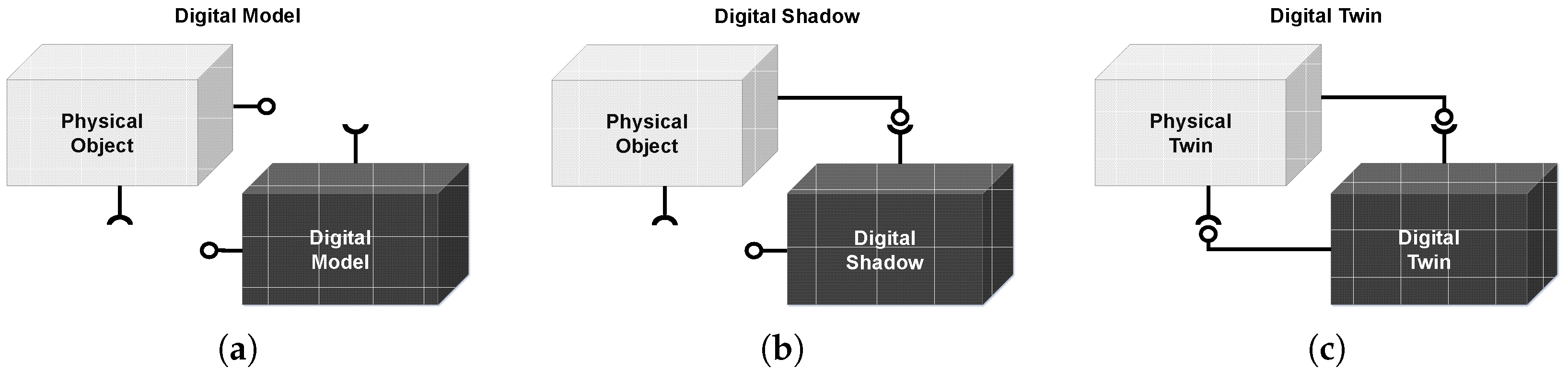
11], who highlighted the critical role of the physical object in the development of digital twins, marking a significant milestone in the categorization and comprehension of this technology.
In short, within the first sub-category, illustrated in
Figure 1a, known as the digital model, there is an absence of direct connection and automated data exchange between the physical object and the digital model. Changes in the state of the physical object do not immediately impact the digital model, and vice versa. When there is a one-way automated data flow from the physical object to the digital model, it falls under the category of a digital shadow, as depicted in
Figure 1b.
Figure 1c represents a fully integrated digital twin, where automated data flow seamlessly in both directions between the physical twin and the digital twin. A change in the state of the physical twin directly results in a corresponding change in the state of the digital twin, and vice versa.
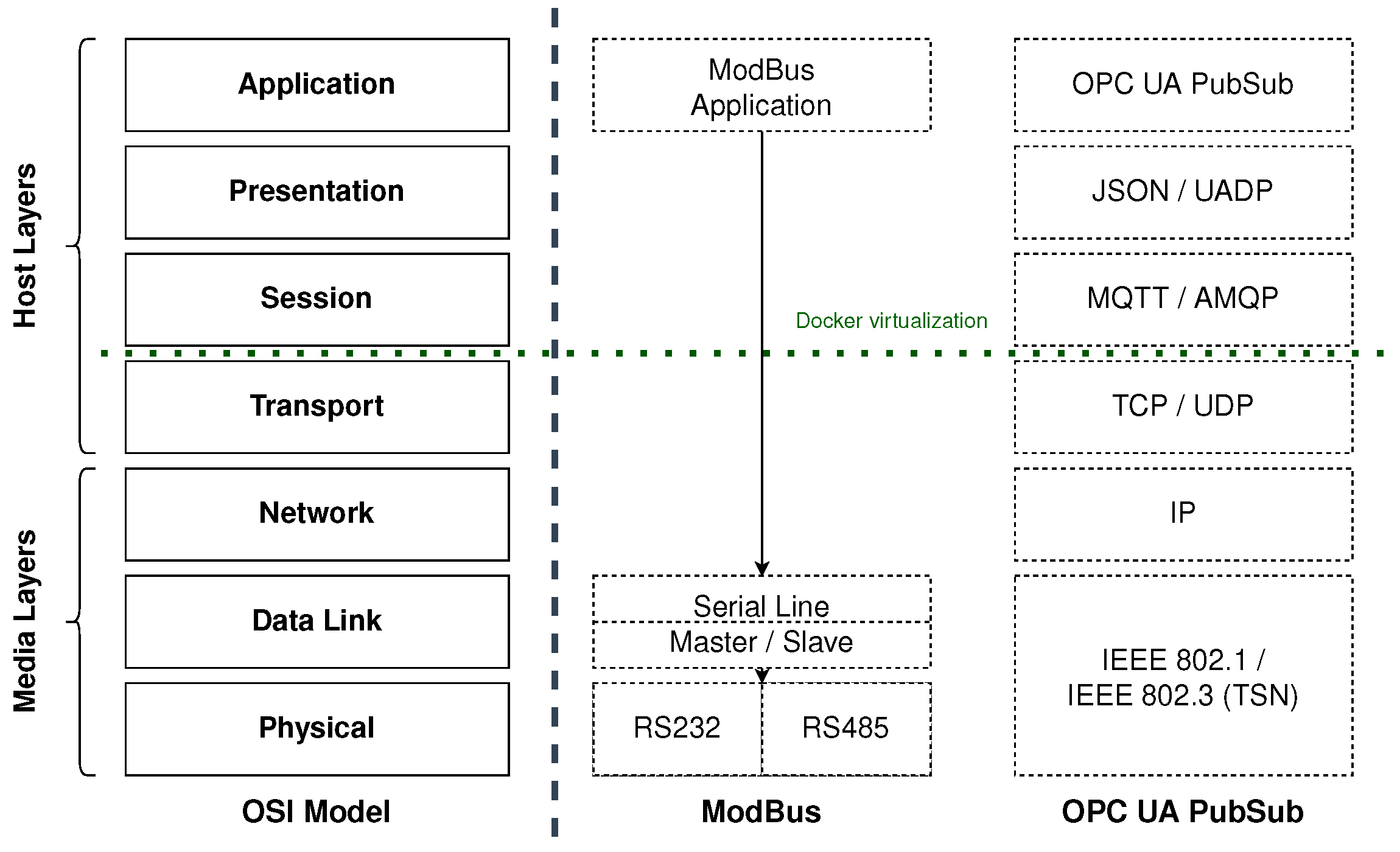
Within this context, the physical object plays a crucial role as the source for the digital shadow, an essential and integrated component of the digital twin. This is notably exemplified in HIL workflows, where engineers still connect a physical object to software running in their integrated development environment (IDE), e.g., VSCode, to validate the incoming data and probably develop new functions based on that. However, this approach is not without its limitations, often leading to constrained access and inconveniences, particularly when multiple engineers are involved. Even with the use of asynchronous collaboration tools, the challenge of collaborative work on embedded software systems remains, as engineers persistently require direct access to the hardware. One of the reasons for the persistent need for a connection to real hardware can be elucidated through the open systems interconnection (OSI) model; see
Figure 2. The embedded community extensively relies on various industrial interfaces and communication protocols, encompassing ModBus, OpenCAN, OPC-UA, or MQTT, among others. Notably, hardware interfaces like RS232/RS485, utilized by ModBus, establish direct access from the application layer to the data link/physical layer. This stands in contrast to network protocol-based interfaces like OPC-UA. Over time, various protocols have undergone significant evolution. For example, ModBus features two protocol standards: one for serial line [
12] and another for TCP/IP over Ethernet [
13]. Similarly, OPC, initially a server/client protocol, adopted a subscription model based on the Observer pattern with Version 1.04, and subsequently integrated a full publish/scrube mechanism using MQTT into the standard with Version 1.05 [
14]. This distinction underscores the ongoing necessity for direct hardware access in specific scenarios.
Modern modeling and simulation tools can easily create a digital twin that mirrors an individual component or process. However, challenges arise when dealing with complex Industry 4.0 applications that necessitate the integration of multiple sensors and actuators into a larger system. This challenge lacks straightforward solutions. Conventional practices in embedded software development have emphasized automation through the use of microcontrollers. In many Cyber–Physical Systems (CPS), programmable logic controllers (PLCs) are used for connecting sensors and actuators. Engineers develop programs within these PLCs. Unfortunately, this conventional approach often results in a predominantly monolithic software architecture, as the device is commonly viewed as a single, homogeneous black-box system [
3]. Inputs from sensors and actuators are conveyed to the controller, processed by the code, and subsequently manifested as outputs or used to trigger actions. Consequently, any modifications to sensors or actuators necessitate corresponding alterations to the source code and any subsequent actions. Moreover, PLC hardware and firmware are frequently proprietary and not publicly accessible, which, when coupled with the prevalent development approach, can give rise to security risks [
15].
Although the event-driven architecture paradigm has existed for decades [
16], its adoption in embedded software has gained popularity only recently, coinciding with the ascent of Industry 4.0 applications. Historically, embedded software systems were implemented as state machines, where engineers dictated the sequence of commands and data manipulation, maintaining full control over the system’s behavior. In contrast, Industry 4.0 applications emphasize autonomous behavior as a central element. While behaviors can be trained, they are not always precisely predictable. Consequently, software components must respond to the data (events) they receive rather than being strictly controlled by engineers. This shift from control flow to data flow is a defining characteristic of Industry 4.0 software architectures.
The growing popularity of event-driven architectures has given rise to novel software architectural paradigms and corresponding middleware solutions, significantly altering the landscape of Industry 4.0 application development. Event-driven architectures have paved the way for the potential replacement of large monolithic applications with microservice architectures [
17]. Microservices are particularly well-suited for distributed Internet of Things (IoT) applications, where each sensor or actuator is associated with a corresponding device driver, often constituting the smallest service that can interact with these devices. Even more intricate tasks, such as waiting for a signal from one sensor and subsequently triggering an action in an actuator, can be implemented as microservices.
We advocate the use of event-driven architectures that employ the publish/subscribe model for asynchronous communication between microservices. This approach fosters the creation of an architecture characterized by loosely coupled nodes and minimal inter-dependencies. Loose coupling and reduced inter-dependency offer the advantage of swift microservice replacement when components of an IoT application undergo changes. Consequently, this contributes to the establishment of a more resilient architecture where the failure of individual processes does not result in system-wide crashes. Such robustness is particularly vital in extensive industrial applications with numerous diverse components. It is worth noting that while this approach enhances resilience, it may also introduce increased complexity in terms of development and maintenance.
As software complexity continues to rise, the importance of automated testing grows significantly. However, robust software testing for communication protocols presents challenges due to the inherent difficulty of emulating or simulating them. Software engineers often resort to the use of mock-up functions in unit tests to avoid actual data exchange between processes, thereby allowing for them to obtain expected values. Nevertheless, even thorough unit testing with comprehensive coverage of edge cases may fall short. Consequently, some approaches employ simulation tools to replace communication protocols between hardware components with software interfaces. The effectiveness of such simulation hinges on how it replaces the communication protocol and its applicability in the development of embedded software systems.
It is essential to note that interfaces that bypass the network layers and directly link the application layer to the hardware layer (as depicted in the OSI model in
Figure 2) are challenging to simulate. Therefore, simulation tools often offer interfaces where real hardware can be connected, often via RS232, when these modules are available. In cases where such modules are not present, an alternative approach involves providing an interface that emulates the same data packet structure, but the connection remains at the application layer. For example, a component that originally used an RS232 connection may need to establish a network socket connection to send/receive data from the simulation tool. Consequently, the software configuration linked to the simulation differs from the software operating in the physical twin, leading to a divergence between the software in the development environment and the real system.
In the context of Industry 4.0 applications, both conventional approaches prove inadequate, primarily because insufficient testing can pose risks to the safety of human operators. Nevertheless, simulation tools remain indispensable in the development of Industry 4.0 applications as valuable sources of data for sensors and actuators. We propose an alternative approach that involves emulating the hardware interface connecting a device driver to a sensor/actuator through virtualization. This emulator is subsequently linked to a simulation tool to extract data from the simulated sensor/actuator. Remarkably, device drivers can connect seamlessly to either real or emulated sensor/actuator interfaces without necessitating changes to their configurations. Emulators have the flexibility to employ either existing observed data or data from simulations, establishing a reliable reference point for the device driver without requiring a physical connection to a real sensor/actuator. This virtualization additionally enables the utilization of sensor/actuator controls in automated tests or throughout the development process. We refer to this innovative approach as the digital twin prototype approach.
Definition 1 (Digital Twin Prototype)
. A digital twin prototype (DTP) is the software prototype of a physical twin. The configurations are equal, yet the connected sensors/actuators are emulated. To simulate the behavior of the physical twin, the emulators use existing recordings of sensors and actuators. For continuous integration testing, the digital twin prototype can be connected to its corresponding digital twin, without the availability of the physical twin.
In this scheme, the digital twin prototype effectively assumes the role of the physical twin in communicating with the digital twin, thereby facilitating the testing of digital twin software without the need for access to a physical twin. Notice, that Grieves and Vickers [
9] referred to a CAD model already as a digital twin prototype. However, according to the categories by Kritzinger et al. [
11], this is only a digital model.
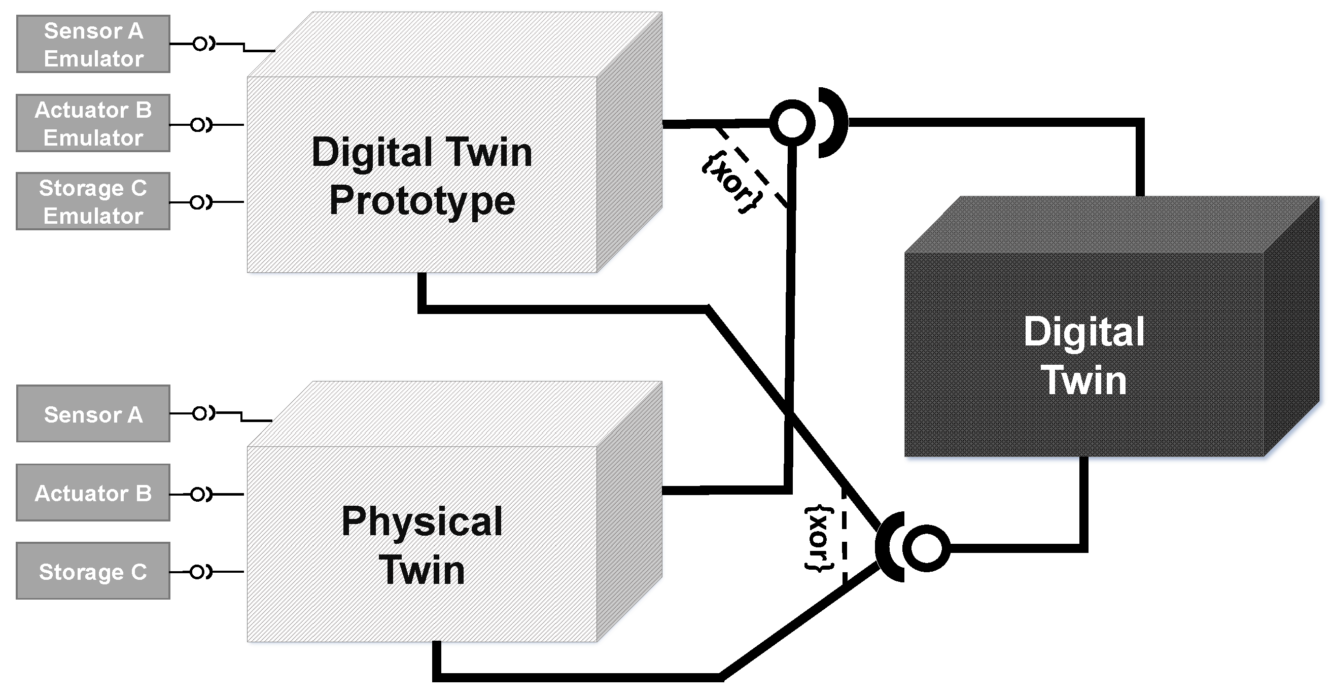
The relationships among a physical twin, digital twin, and digital twin prototype in our approach are illustrated in
Figure 3. The digital twin prototype closely mirrors the software configuration of its corresponding physical twin but utilizes emulated sensors/actuators in place of real ones. The digital twin may share certain software logic components with the physical twin, albeit without connected sensors and actuators. Additionally, it could incorporate additional logic for managing both the physical twin and the digital twin prototype. This approach seamlessly integrates all interfaces into the development process, ensuring that the inputs and outputs of the emulated hardware align with those of the real hardware. The emulators respond to the same commands and generate data packets in formats identical to their real counterparts. Consequently, the digital twin prototype serves as a reliable source for creating a digital shadow. In other words, it acts as a prototype of the physical twin and can effectively substitute it during the development phase or for automated testing of the embedded software system.
Figure 4 illustrates the fundamental concept of a digital twin prototype setup with interfaces. A device driver associated with a physical object employs a virtual hardware interface to establish a connection with an emulated sensor/actuator. These emulated sensors/actuators may utilize recorded data, such as data acquired during real deployments, to provide virtual context. Alternatively, if real data are unavailable, a simulation is employed.
Within the simulation tool, corresponding sensors/actuators are simulated, and data exchange occurs through software interfaces. In either scenario, the emulators impart virtual context to the device driver. In a well-executed implementation, the device driver is unable to distinguish whether it is interfacing with a genuine sensor/actuator or an emulator. Further details regarding the implementation of the digital twin prototype will be presented in a separate publication. An example of a basic integration test, where a device driver is connected to a device emulator through an RS232 interface, is available in our GitHub repository [
18].
Containerization and Enabling Virtual Hardware Interfaces
In the absence of containerization, developers are required to initiate all components as processes within their IDE to substitute a physical twin with a digital twin prototype. This process is notably cumbersome, particularly when it involves maintaining dependencies and keeping configurations up to date. Even minor disparities between two development environments can lead to extensive working hours spent on debugging and issue resolution.
Containerization of embedded software systems presents three primary advantages for the digital twin prototype, including the following:
it ensures that the base container consistently maintains the same clean setup, thereby eliminating dependency and configuration conflicts;
it introduces an intermediate layer between the transport and session layers, as depicted in
Figure 2. This intermediate layer facilitates the use of tools like Socat to establish a serial connection connection and bind it to a TCP socket. Consequently, RS232/RS485 emulation is achieved without transitioning from the application layer to the physical layer. The entire process remains within the application layers, and the software is oblivious to whether it is connected to a real RS232 interface or an emulated one via Socat;
it enables platform-independent software development, ensuring compatibility across various development and deployment environments.
As a consequence, integrating digital twin prototypes with virtualization enables engineers to develop new software modules within their local IDE without the need for a constant connection to a physical test bed. A fully virtualized digital twin prototype is ideally suited for provision as a Software-as-a-Service (SaaS), allowing for engineers and domain experts to conveniently experiment with the system. In the realm of digital twins, Aheleroff et al. [
19] refer to this concept as Digital-Twin-as-a-Service (DTaaS).
Nevertheless, prior to deployment in a production environment, comprehensive testing on the physical twin remains a necessity. This is essential because performance tests can only be reliably conducted on hardware that precisely replicates the production setup. However, it is worth emphasizing that digital twin prototypes facilitate the independent testing of software logic, irrespective of access to hardware components.
3. Related and Previous Work
Since 2018, there has been a notable evolution in IoT platforms, transitioning from basic data hubs to encompass digital twin platforms. Lehner et al. [
20] conducted an evaluation of digital twin platforms offered by Amazon Web Services (AWS), Microsoft Azure, and the Eclipse ecosystem. Their assessment revealed that while these platforms fulfill numerous requirements, they do not fully address all key requirements. Notably, features like bidirectional synchronization between physical and digital twins necessitate additional coding efforts, and automation protocols remain uncovered [
1].
In alignment with the established categorization of digital twin integration levels proposed by Kritzinger et al. [
11], these platforms primarily facilitate the establishment of what is commonly referred to as a
digital shadow. Consequently, modern simulation tools such as AutoDesk, aPriori, or Ansys integrate IoT platforms to provide data for simulations and enable the incorporation of automation protocols. It is important to note that these simulation tools are often marketed with the promise of a digital twin. However, similar to the cloud providers, these tools also primarily contribute to the creation of a digital shadow [
1].Furthermore, it is essential to recognize that the simulation of a physical twin typically does not encompass the entire embedded software system that operates on the physical twin. Additionally, it lacks the capability for proper bidirectional synchronization between the physical twin and the digital twin [
1].
The utilization of robotic systems in smart farming applications is not a novel concept. Shamshiri et al. [
21] provide a comprehensive overview of use cases, the current state-of-the-art in agricultural robotics, and the associated challenges. These overarching challenges in smart farming align with those encountered in other domains: digitalization, automation, and optimization. Moreover, it is important to recognize that all robotic applications grapple with the common challenges inherent in embedded software systems. Research on digital twins in the context of agriculture is still in its early stages. One potential explanation for this could be the varied interpretations of digital twins in the agricultural context, which encompasses living entities such as digital twins of animals and crops [
22]. This introduces a distinct research domain separate from robotics. In contrast, our case study exclusively focuses on digital twins of agricultural machinery.
In the manufacturing sector, Industry 4.0 emphasizes automation and efficiency, whereas smart farming technologies aim to complement and enhance farmers’ capabilities, not replace them. These technologies include tools for decision-making support, data analytics for insights, and automation of routine tasks. This integration of technology and human expertise in smart farming leads to personalized, environment-friendly agricultural methods and resilient strategies that adapt to changes. Further, this evolution underscores a more human-centric approach in technology-driven industries, valuing the role of humans in the industrial process. The highlight of collaboration between humans and smart systems aligns with the principles of Industry 5.0 [
23]. Pylianidis et al. [
22] proposed a roadmap in which they outlined the evolution of agricultural digital twins [
1]. The initial stage involves components like monitoring, user interfaces, and analytics. Subsequently, actuators are introduced to enhance the capabilities of digital twins. In the third stage, simulations are incorporated to facilitate decision making based on historical data and future predicted states of the physical twin. This evolution continues with the integration of artificial intelligence (AI), ultimately culminating in the creation of a digital twin of the Earth.
In addition to the digital twin definition proposed by Kritzinger et al. [
11], we drew upon the digital twin definition provided by Saracco [
24] and presented a proof of concept of our approach in Barbie et al. [
8]. The development and field testing of the digital twin prototype approach took place within the context of the ARCHES project (Autonomous Robotic Networks to Help Modern Societies). ARCHES was a Helmholtz Future Project featuring a consortium of partners including AWI (Alfred-Wegener-Institute Helmholtz Centre for Polar and Marine Research), DLR (German Aerospace Center), KIT (Karlsruhe Institute of Technology), and GEOMAR (Helmholtz Centre for Ocean Research Kiel).
Within the framework of the ARCHES project, we undertook the development of several digital twin prototypes for ocean observation systems. Our primary objective of this project was to implement robotic sensor networks capable of autonomously adapting their measurement strategies in response to environmental changes, both in space and deep-sea environments. The AWI and GEOMAR research institutes focused on developing an underwater network, facing challenges not only in implementing acoustic communication but also due to the considerable distance of about 250 km, which made it logistically challenging to develop and test different platforms at a single site. The COVID-19 pandemic further complicated matters, necessitating remote implementation of these systems. Primarily, the communication protocols used were RS232/RS485-based.
Our digital twin prototype approach enabled the creation of emulators for both the embedded control system and acoustic communication.
Figure 5 in our documentation illustrates the application of our digital twin prototype concept, as initially presented in
Figure 3, within the ARCHES project. During the early development phase, we employed an HIL approach to evaluate the RS232 protocol. Subsequently, we transitioned to SIL with digital twin prototypes for the comprehensive implementation of control systems.
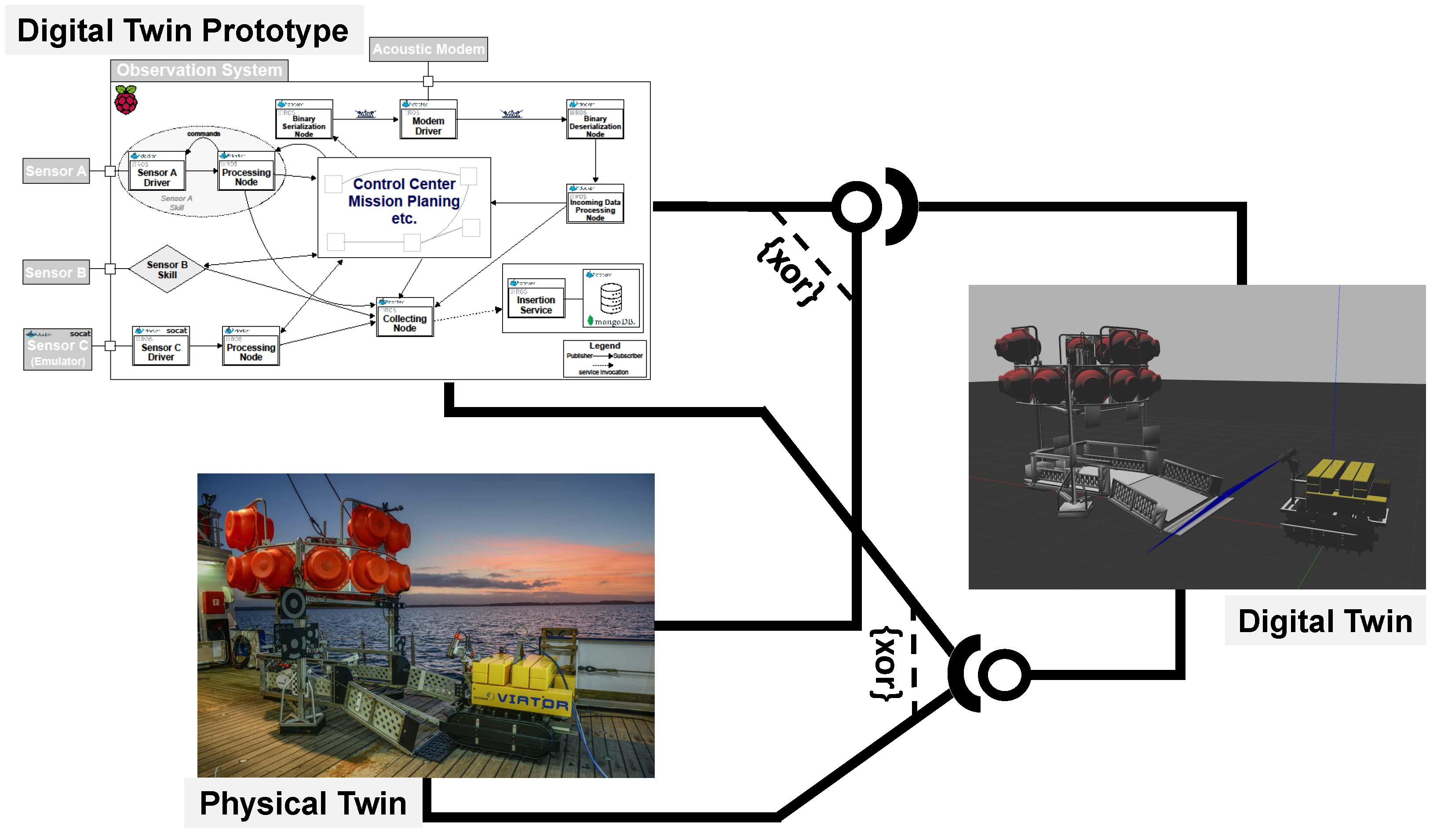
Rather than creating additional software for monitoring the underwater network, we utilized the digital twin prototypes. The setup of this network is depicted in
Figure 6. An acoustic modem on the research vessel facilitated data transmission and reception. This modem was linked to a server where each observation system had its corresponding digital twin operating, effectively functioning as a digital twin. Through this method, data transmitted by a physical twin were received and logged by their digital twin. Conversely, commands initiated at the digital twin prototype were dispatched to the physical twin underwater. This system ensured that all messages exchanged between the physical and digital twins during the mission were recorded.
This approach was evaluated as part of a research cruise during which a collaborative underwater network of ocean observation systems was established and deployed in the Baltic Sea [
1]. A detailed field report on the utilization of digital twin prototypes in this context was published by Barbie et al. [
8]. Throughout the cruise, a series of scenarios were conducted to showcase the viability of digital twins in maritime environments.
In one scenario, we demonstrated the collaboration between a physical twin and its digital twin. Furthermore, we captured the moment when two ocean observation systems, Mansio and Viator, received a broadcast from the research vessel. This video is available in our GitHub repository [
8,
18]. On the left side of the video, the digital twins of Mansio—a stationary sensor hub—and Viator, a crawler equipped with a camera, are displayed. In this scenario, we broadcasted a command to the network, altering the behavior of all systems. The video captures Mansio activating its lights and Viator slowly moving backward. A split-screen format is used to show that the digital twins replicate the actions of their physical counterparts with a minor delay. The ARCHES Digital Twin Framework, developed during the ARCHES project, was released as open-source software [
25].
During the ARCHES demonstration mission, we also highlighted the usage of a digital twin prototype in combination with a simulation for monitoring the behavior of underwater ocean observation systems [
8]. A video demonstrating a scenario in which physical twins and digital twin prototypes respond to the same broadcast command in a split-screen view is accessible on GitHub [
18].
DevOps and Continuous Twinning with Digital Twin Prototypes
In a comprehensive literature review, Garousi et al. [
26] found that test automation is one of the most prominent subjects in testing embedded software. Nevertheless, ensuring automatic quality assurance remains a significant challenge, primarily due to the involvement of hardware in the testing process. Their study, [
26], revealed that the predominant testing technique involves using real systems; however, simulated systems, such as MIL, HIL, SIL, or PIL, are also widely employed. Testing on the actual system necessitates a permanent connection to the testing environment, which can be costly and impractical, particularly for SMEs. This is the reason why the digital twin prototype focuses on being independent from the real system while still supporting the testing of real embedded software.
The embedded software community has already made successful strides in implementing continuous integration tools alongside source control management tools like Git, with a primary focus on unit testing. However, similar to conventional software engineering, development teams are not always engaged in operating the software system, leading to potential challenges arising from insufficient communication, collaboration, and integration [
27]. To address this issue, Bass et al. [
28] introduced the concept of DevOps (Development and Operations), a software development approach that places significant emphasis on fostering collaboration and communication between development and operations teams. The primary objective of DevOps is to accelerate software delivery while maintaining high software quality. It achieves this by automating numerous manual processes, enhancing collaboration and communication among teams, and promoting agile and lean methodologies. Hasselbring et al. [
27] demonstrated that DevOps principles can be applied to Cyber–Physical Systems (CPS) and coined the term “industrial DevOps” in the context of the Industrial Internet of Things (IIoT). Key practices and tools within the DevOps framework encompass continuous testing with CI/CD [
27], monitoring/logging, configuration management, and infrastructure as code.
The digital twin prototype approach enables engineers to produce the first minimum viable product (MVP) with the first implemented device driver and emulator. Due to the publish/subscribe architecture, all further nodes and emulators can be developed and added iteratively. Putting all modules in a source code management system allows for all developers to use the digital twin prototype and enhance the entire system incrementally, without the need to connect to the hardware of the physical twin. As a bonus, this also enables automated SIL testing in continuous integration/continuous delivery (CI/CD) pipelines. By following CI/CD workflows, the development of embedded software systems becomes an agile and incremental process. Beginning with a prototype of a driver for a single piece of hardware, spanning entire production plants, and smart factories, agile software development is enabled. This not only improves the software quality and shorten release cycles, but it also allows for additional stakeholders to participate in a feedback loop during the development process of the first minimum viable product. Adjusting software requirements or fixing design flaws can be achieved during development. With this method, digital twins evolve continuously in small incremental steps rather than in major releases. Nakagawa et al. [
29] envision and call this approach
continuous twinning.
The idea of evolving ocean observation system accompanied us also in ARCHES. From the beginning, we followed a CI/CD workflow in GitLab, encapsulating ROS in Docker and automatically test the system. In this pipeline, we used not only a SIL approach, but also a PIL approach. All ocean observation systems had a RaspberryPi 3b+/4 executing the core software and handling and handling the network communication. For each version, we had to connect a build agent to the GitLab server, as the RaspberryiPi 3b+ has a 32-bit ARM processor and the RaspberryPi 4 a 64-bit ARM processor. Hence, the Docker containers had to be built, tested and released for three different processor architectures to be available at any time. The recorded data from the demonstration mission can provide valuable data to enhance the quality of the CI/CD pipelines.
In line with the roadmap outlined by Pylianidis et al. [
22] for integrating digital twins in smart farming applications, it is anticipated that these applications will eventually incorporate AI at some point. Steidl et al. [
30] conducted a multivocal literature review on how AI could be included in the DevOps and CI/CD process.
6. Results and Discussion
After the initial idea of SilageControl was formed, we extended an invitation to the team to visit the GEOMAR Helmholtz Centre for Ocean Research in Kiel. During this meeting, we took the opportunity to showcase our ongoing research on ocean observation systems, aiming to provide valuable insights and support for SilageControl’s development journey. Given the modular nature of SilageControl’s sensor bar, which is mounted on tractors, and the team’s intention to employ ROS as middleware in their software architecture, our objective was to share our expertise in embedded software development using ROS.
During the meeting, we seized the opportunity to involve a group of students whom we co-supervised in a master’s project. This collaboration allowed for us to conduct tests and demonstrations of a web application designed for real ocean observation systems. The relevance of this endeavor closely paralleled the SilageControl concept, where sensory data need to be visualized in a web application [
1]. In scenarios like this, the use of a web application or a digital twin becomes imperative. As the tractor maneuvers to compact the silage heap, users require real-time or near-real-time monitoring to promptly detect possible sensor failures or software glitches. Delayed identification of such issues could result in sub-optimal compaction which may lead to spoilage of the silage and substantial losses.
6.1. The Challenges in the Development Workflow
During the second meeting, we conducted an interview with the lead engineer from the SilageControl team to delve into the development workflow associated with the integration of sensors into the SilageControl system.
The lead engineer described a typical HIL development workflow for integrating sensors into the SilageControl system during the interview. The process begins with testing the sensor on a PC, where they identify required device drivers, install them, and ensure compatibility. They validate the sensor’s outputs on the PC to confirm they meet the expected results. Some sensors require specific coordinate systems, which are also checked during this phase. The next step involves physically installing the sensors on the platform, following a hardware manual and seeking input from the sales team if needed. Device drivers are verified in the pipeline, and Docker is used for building them for deployment to the mobile platform. However, the engineer acknowledged challenges when integrating certain sensors, such as GPS, into the system. GPS sensors need an unobstructed view of the sky, making testing in an indoor office setting difficult. Transitioning to outdoor testing poses challenges in setting up the sensors correctly and ensuring the required power supply, which remains an unresolved issue for the team.
As previously emphasized, embedded software development frequently encounters the dilemma of testing hardware in a suitable environment. An example of this issue is the integration of a GPS sensor in an office setting. The target system’s size often makes it impractical for office testing, while field testing on a tractor is both costly and time-consuming. To address this challenge, engineers often detach the hardware from the target system and relocate it to a laboratory environment. However, if a sensor only functions as intended in the field, this predicament becomes even more pronounced and can significantly impact the entire development process. We encountered similar challenges in the ARCHES project, as outlined in
Section 3, where the ocean observation systems were too large for our office spaces or were unavailable due to other research cruises [
8].
Silolytics conducted their first experiments in 2020, subsequent to their visit to GEOMAR. During our discussions, we also inquired about the insights and lessons they gained from these initial experiments:
“We spent approximately 400 h testing our system and collecting data from various use cases to cover as many scenarios as possible. Using this data, we developed our algorithms during the winter months, focusing primarily on perception, which involves recognizing the surrounding environment and identifying the building’s structural features automatically. We then integrated the entire workflow into the app and tested it offline, which was challenging due to the lack of available data for testing. However, we recorded various use cases, which we can now use to test the system’s functionality. We created launch files with [ROS] bag files to test our software and algorithms and evaluated them using different metrics. For instance, we assessed the importance of sensor alignment and the accuracy of LiDAR detection. We used this approach in our development workflow to ensure that our system meets the required standards.”
Gathering realistic and reusable data from sensors and actuators presents a significant challenge in the development and testing of embedded software systems. To tackle this issue, the team utilized their initial trial period to extensively collect data from the sensors and actuators. They systematically stored all the ROS messages transmitted within the system in ROS bag files, which are capable of being replayed at a later time. The publish/subscribe architecture proved to be highly advantageous for logging, as it enabled the subscription to all topics, capturing all incoming messages. With the built-in playback functionality offered by ROS, the entire scenario could be effectively replayed within an office setting. These collected data also served the purpose of facilitating DevOps practices. Notably, if any defects were detected during the initial testing phase, these data could subsequently be employed in automated tests to validate the implemented fixes. Given that a simulation of the tractor with the sensor bar was unavailable at that time, this approach was the sole means of acquiring “real” data for testing.
We further sought to understand their positive and negative experiences with this workflow:
“I really appreciate the automatic building of packages [with Docker]. It is quite straightforward to pull the packages onto the Jetson Nano later on. All you need to do is download the images. Additionally, GitHub has Docker registries where you can easily deploy your packages. I find it helpful that pushing to the latest branch results in the package being built automatically. If we were to do this manually, it could lead to problems, but with the base image, all dependencies are included. By shifting the problems, we only need to do it once in Docker, which is much more convenient than using SSH or connecting a monitor to pull everything onto the Jetson Nano. This is actually the main advantage, as you only have to do it once and not repeatedly.”
The engineer highlighted several challenges as part of their negative experiences. Firstly, they encountered issues with certain sensor drivers that functioned with older versions of ROS but were not compatible with the current long-term support (LTS) version. For example, when ROS Noetic, the last LTS version of ROS Version 1, was released in 2021, some of their device drivers only supported the previous ROS Melodic version. This necessitated manual adjustments, implying that future updates might not be automatically incorporated into the Docker container. However, the advantage of a modular publish/subscribe architecture combined with containerization is that individual modules could run on different versions than the rest of the system, facilitating cross-distribution execution between ROS Melodic and ROS Noetic. Any potential build breakages resulting from new versions, whether of ROS or any dependencies, could be automatically tested in a CI/CD pipeline, such as a nightly build. Secondly, they encountered a significant challenge when a LiDAR sensor malfunctioned after only a few hours of use, incurring substantial costs, which was a notable issue in their context. Thirdly, they faced difficulties with software documentation, particularly for device drivers, which was often either unavailable or inadequately maintained. The team encountered the most challenges with the LiDAR sensor, necessitating multiple trials with different models before selecting the appropriate one.
Given the engineer’s frequent mention of Docker, we inquired whether they started using Docker before or after their meeting at GEOMAR and whether it was employed solely for deployment and testing or also for development purposes. The engineer confirmed that they began utilizing Docker for deployment and automated testing after their meeting with us, as it had not been used for development before that point [
1].
“[…] When everything is in Docker containers, and you have to rebuild and change the images, you do not make as many changes anymore. It becomes more important that it works and is thoroughly tested. This also makes the entire deployment process more comprehensible.”
This revealed a misconception regarding the potential use of Docker in development. Docker actually provides the capability to mount folders into a container, enabling the straightforward integration of the ROS development environment into the container. This means that the ROS development environment can be easily attached to the container and initiated from there, eliminating the need to reconstruct the image and create a fresh container. We emphasized this aspect during the interview. In all the defined containers within the Docker-compose files in our PiCar-X example available on GitHub [
18], the corresponding source folders are mounted. If there are new nodes or files, they may require adjustments in the build file to make them executable, but the container does not need to be restarted prior to execution. Following the commitment of changes, the CI/CD process tests the altered source code, constructs a new container, and, upon successful testing, publishes it to make it accessible to all collaborators.
6.2. The Challenges for Product Customization and Quality Assurance
The third segment of the interview delved into the customization of SilageControl and its quality assurance workflow. Given that SilageControl is constructed upon a modular software architecture, the adaptation of sensors and their drivers is considered throughout the system’s development. Additionally, the challenge of mounting the sensor bar properly is acknowledged, as tractors and other agricultural machinery lack standardization, and various manufacturers produce them. In terms of customizing the sensor bar, SilageControl gained insights from their initial experiments:
“[During our first trials], we had to [manually] position the system [(the single sensors)] precisely to the tractor during installation, which made it peculiar and inconvenient. [Since then], we improved the installation and introduced a rail containing the sensors that can now be mounted on the tractor in various ways. Additionally, we have standardized the rail’s structure, which allows for calibration routines to run beforehand, and the sensors to calibrate themselves automatically. As a result, there is no need for pinpoint accuracy during installation. Before, it was nearly impossible to align everything perfectly. Now, our system is plug-and-play, making it easier to install. To ensure accuracy, we use CNC machines to manufacture the parts, including brackets and mounts. […] Even a slight deviation of just one degree during installation can result in a significant error of 17 cm over a meter, which is far from ideal […]. [Thus,] we are constantly working to improve the installation process and reduce the margin of error to achieve the highest level of precision [and accuracy] possible.”
The engineer previously indicated that the source code is hosted on GitHub, and the build process and unit tests are conducted within GitHub’s CI/CD pipelines. Therefore, we did not inquire about the presence of automated unit tests but instead focused on whether there were automated integration tests involving the hardware within the CI/CD pipeline. This aspect poses a significant challenge for small and medium-sized enterprises (SMEs) with limited resources for additional hardware. Engineers at SMEs typically work on the same hardware employed in production, making it challenging to connect it to CI/CD systems. The engineer confirmed this constraint.
“In my opinion, connecting all the sensors and having a setup to test all the basic functionalities using HIL with synthetic data would be beneficial. This would be relatively easy to implement, and for GPS, using synthetic data would be the simplest option. By doing so, we could test various forms of noise and other aspects. This approach has been well-researched for the sensor type, and it may help us resolve our problem. Although we have considered it, we have not found a solution yet, and we also need to consider the effort.”
This limitation is particularly critical for Silolytics, given that the silage season only occurs between certain dates, making it the only time they have the opportunity to develop their system. During the interval between two seasons, the sensor bar’s development takes place in a HIL environment. The true correctness of the implementation can only be ascertained when it is installed for the first time in a new season. Throughout the silage season, the hardware is seldom available for the developers, complicating the connection of sensors to GitHub or the execution of automated integration tests. Due to the potentially high cost of these sensors, spare sensors are not easily available for use during this period. In this context, software failures could significantly impact the system’s operational time and, consequently, potential revenue. Detecting a software failure during silage making is possible using the monitoring web application. However, resolving the issue requires a series of steps, including dismounting the sensor bar from the tractor, locating and fixing the bug, and then remounting the bar. This process can be time consuming.
To address these challenges, the team has contemplated using simulations to replicate the tractor and sensor bar, creating a virtual environment. Simulations have traditionally been used to address the unavailability of the real system, and while this approach is not new, it has its complexities. Developing an embedded control system in a fully simulated environment can be challenging, as it may not support all communication protocols, particularly serial communication-based protocols. Switching device drivers to a TCP-based connection may not always be feasible, especially if the vendor only provides an RS232-based device driver. A custom implementation is an alternative, but its viability depends on resource availability, which may be limited for SMEs. Furthermore, differences between the device driver in the development and testing environment and the one used in production on the tractor could lead to discrepancies in the embedded control system implementation.
These challenges parallel those we encountered during the ARCHES project. In the development of the underwater network, we lacked the opportunity to test the entire system under real conditions before the demonstration mission. To address this, we used an early adoption of the continuous twinning method, incrementally implementing the entire system and starting and testing the network in our local IDEs. To emulate acoustic communication, we utilized an emulator provided by the acoustic modem vendor. The PiCar-X example is built upon the ADTF [
25], which was also used in the ocean observation systems.
The concept of using simulations as a solution was further elaborated when discussing the quality assurance workflow for SilageControl:
“We intend to use simulations extensively in the future since we have other product development aspects that can only be developed in the simulation and would be too time-consuming otherwise. This is especially true now that we are collaborating with a service provider, and we intend to incorporate the digital twin approach. This is also what we hope to accomplish here with Kiel University in the future. We have already devised a plan for what we intend to change in the future, but we have never had the necessary environment to implement it. Therefore, this will be the primary work package in the near future.”
The challenges mentioned during the interview that Silolytics faces with SilageControl can be summarized as follows:
- Testing the Embedded Control Software in a Suitable Environment:
Integrating sensors and hardware components into the SilageControl system can be challenging due to the need for testing in real-world conditions, which are often different from controlled laboratory settings.
- Sensor Integration:
GPS sensors used in the system require an unobstructed view of the sky, which can complicate testing, especially when transitioning from indoor testing to outdoor field conditions.
- Sensor Malfunctions:
Hardware components, such as LiDAR sensors, may malfunction during testing, and their replacement can be costly.
- Limited Availability of Hardware:
The availability of hardware components is limited, especially during the silage season, making it challenging to connect sensors to CI/CD systems or perform automated integration tests.
- Impact of Software Failures:
Software failures during silage making can have a significant impact on the time the system can be used and revenue generation, as diagnosing and fixing issues requires dismounting the sensor bar and can be time-consuming.
- Resource Constraints:
SMEs like Silolytics may face resource constraints when implementing custom solutions to address these challenges.
- Use of Simulations:
While simulations can be used to overcome some of these challenges, developing an embedded control system entirely in a simulated environment can be complex, especially when not all communication protocols are supported.
- Lack of Documentation:
In some cases, software documentation, especially for device drivers, may be unavailable or poorly maintained, making it difficult for the team to integrate sensors effectively.
Bad documentation of sensor/actuators cannot be effectively addressed using a digital twin prototype, as it pertains to software modules which are external features. The core issue here relates to the embedded software community’s tendency to develop device drivers that are tightly integrated with the overall system, such as a specific middleware. This concern has been highlighted by Kaupp et al. [
36] and Quigley et al. [
34], who argue for the development of device drivers that are independent of the middleware used in the embedded system. The rationale is that dependency on a particular middleware necessitates redevelopment of drivers when switching to a different middleware, even if the hardware’s logic remains the same. Given the plethora of programming languages and middleware options, it is impractical for sensor and actuator manufacturers to create and maintain device drivers for each variation. Thus, from our point of view, it is beneficial for manufacturers to ensure their sensors are easily accessible via APIs and not tied to any specific middleware.
6.3. A Digital Twin Prototype for SilageControl
During our third meeting, we introduced the PiCar-X example to illustrate how simulation could provide a virtual context for a digital twin prototype. At that time, the ARCHES Digital Twin Framework had not been published yet, and Silolytics had already initiated the development of a digital twin using a combination of C++ and Python components [
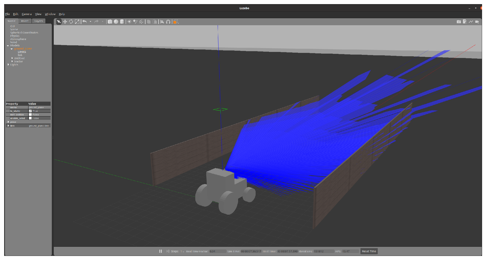
1]. However, as SilageControl decided to adopt the digital twin prototype approach and they shared their progress with us during the fourth meeting. They presented their initial outcomes for their digital twin implementation. In this context, they employed the GAZEBO simulation [
32] to model a simplified tractor including the sensors, as depicted in
Figure 10. This model encompassed the IMU, GPS, LiDAR sensors, and the core logic of SilageControl could be connected to this simulation.
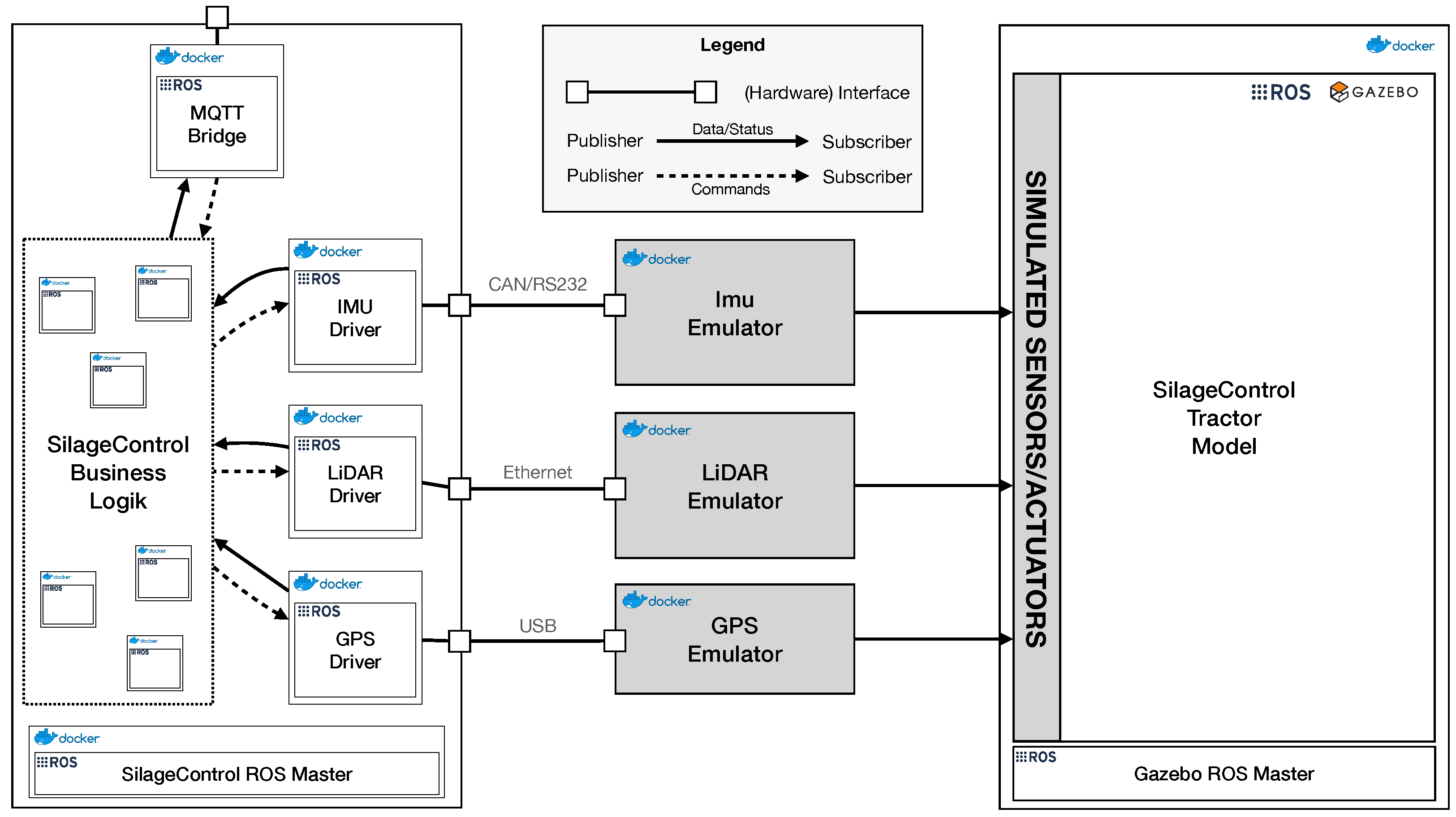
To transition from a physical twin to a digital twin prototype for development and testing purposes, the subsequent step involved linking the device drivers to emulators connected to the simulation, as illustrated in
Figure 11. These emulators received commands from the device drivers through different interfaces (Ethernet, RS232, and USB) and relayed these commands to the GAZEBO simulation. Subsequently, the simulated sensors in GAZEBO reacted to the transmitted commands, producing simulated data that were then sent back to the emulator. Finally, the emulator forwarded these data to the corresponding device driver for further processing.
The conventional approach involves incorporating the emulator logic as a module directly into the simulation. However, as previously discussed, this approach has several challenges and drawbacks. Notably, tightly coupling an emulator to a specific simulation tool makes it challenging to transition to another simulation tool. To address these issues, we propose, with the digital twin prototype, a different approach, where the emulator logic is separated, and only an interface is added to the simulation. This approach offers more flexibility, allowing for an easier switch to different simulation tools if needed. Additionally, it provides Silolytics with the option to use recorded data, such as data from ROS bag files, for replaying to the emulator rather than relying solely on simulated data. This flexibility prevents vendor lock-in from the early stages of development.
With an existing build pipeline in place, the next step for Silolytics involves writing tests for their digital twin prototype. The GAZEBO simulation can be initiated in a headless mode, without a graphical user interface, making it ideal for testing and reducing overhead during the testing process. Our PiCar-X example includes an integration test that launches GAZEBO in a headless mode [
18].
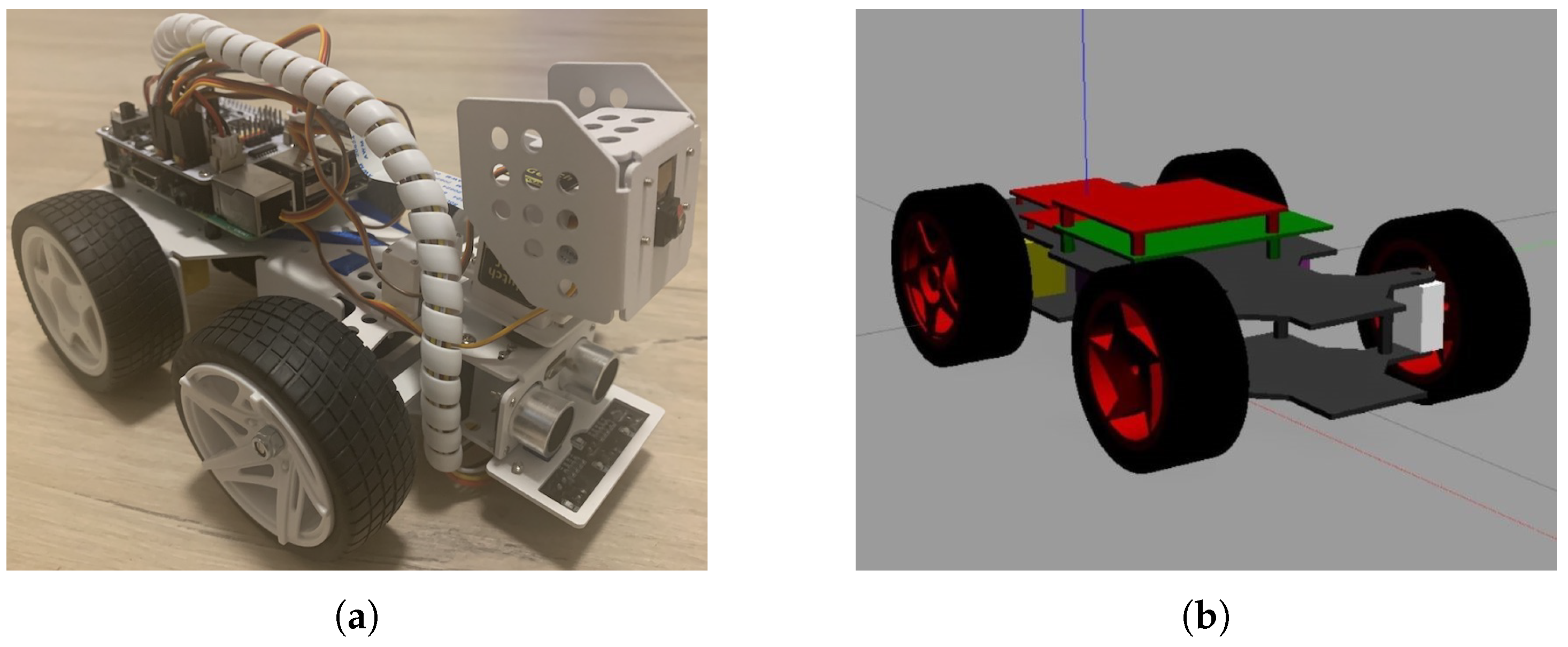
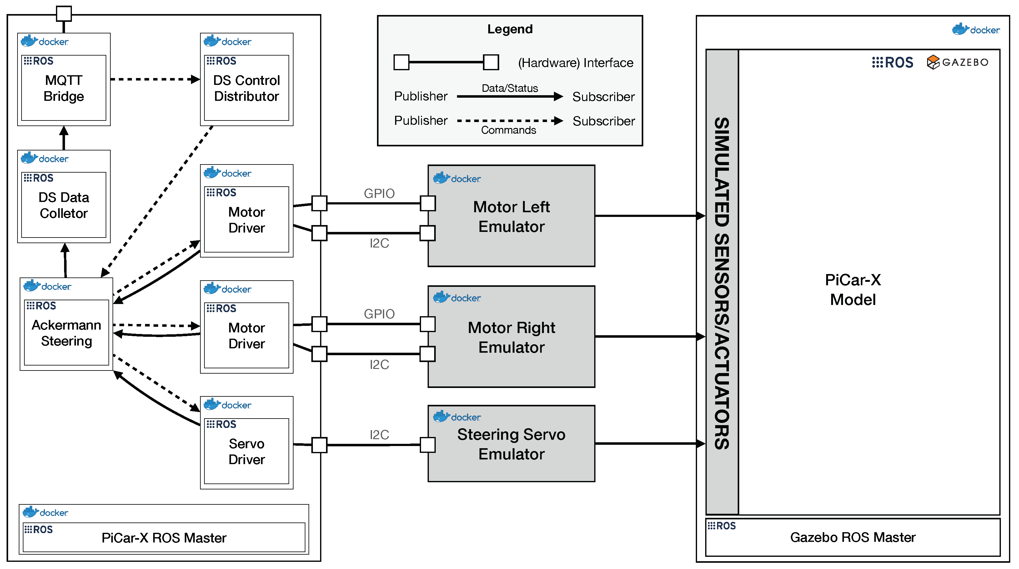
While the digital twin prototype of the tractor was not completed at the time of this paper’s publication, our PiCar-X digital twin prototype example also utilizes ROS in combination with Gazebo and emulators between the embedded control system and the simulation, as shown in
Figure 9. The hardware interfaces in this example are GPIO and I2C instead of RS232, but we provide an example of how to establish an emulated RS232 connection via socat in our GitHub repository [
18]. The PiCar-X example includes a basic integration test that can be executed using a Docker Compose file. This test ensures that the digital model in the simulation moves at a speed comparable to its physical counterpart in the real world. Given that ROS Noetic lacks real-time capabilities, we verify whether the model moves a distance within an interval of five centimeters around the expected one meter. Following the continuous twinning paradigm, more complex tests for a full digital twin prototype could involve scenarios such as line following and obstacle detection.
6.4. Threats to Validity
We identified three threats to the validity of our case study. Firstly, the case study was not initially conducted with a strict research plan and the idea developed over time. Secondly, this is a single case study, which might limit the generalizability of the findings. Thirdly, we had prior knowledge of the Silolytics GmbH and its team before conducting the interviews and already presented them our results from the ARCHES project. This might have influenced their development process, and although the interviewed engineer did not know the questions beforehand, he may have guessed the intentions behind the different questions and answered them accordingly.
7. Conclusions
As outlined in the introduction, engineers commonly encounter a range of challenges during the development of modern and complex embedded software system. This is not different for the engineers of the Silolytics GmbH. Within the ARCHES project, we detail our approach to these challenges through the development of a digital twin prototype [
8]. For example, by virtualizing hardware into a digital twin prototype and integrating it with simulation, as demonstrated in our PiCar-X case, we can utilize a virtual context for development and testing. This digital twin prototype mirrors the physical twin and not only facilitates development but also enables monitoring of the physical system in operation. It allows for data collection from, for instance, Silolytic’s sensor bar on a tractor, without needing a physical connection. This approach significantly reduces the need for, and cost associated with, physical hardware in embedded software system development.
Digital twin prototypes are particularly beneficial in addressing some of the challenges faced by Silolytics in developing and testing SilageControl. A digital twin prototype creates a virtual environment that accurately replicates the physical system’s behavior and characteristics, thereby enabling a more realistic integration of sensors and hardware components into an embedded software system. This reduces the necessity for extensive field testing. However, it is important to note that “realistic” here implies the use of high-quality models. While the current model, as shown in
Figure 11, is somewhat abstract, it provides a foundation for ongoing development and testing of the embedded control system, including communication protocols, without relying on physical hardware. This not only minimizes costs but also mitigates risks associated with hardware failures during the development process.
Another advantage of using a digital twin prototype in the development of SilageControl is the flexibility it offers. Developers can work on individual instances of the digital twin prototypes, independent of physical hardware, within their local IDEs. This enables parallel development and reduces reliance on limited hardware resources. Moreover, it enables parallel development without the need for spare hardware and facilitates the integration of the system into a CI/CD pipeline. This can be achieved using freely accessible tools like the community version of GitLab [
37] or GitHub Actions. By adopting this method, small enterprises can effectively embrace the continuous twinning approach from the outset of a project, streamlining their development processes and maximizing efficiency. In particular, for small enterprises operating on a limited budget, this approach is beneficial.
Implementing a digital twin prototype in a local development setting also facilitates the creation and testing of various “what-if” scenarios and conditions [
24]. These scenarios may be challenging to replicate in real-world settings. Engineers can test the system under diverse environmental conditions, sensor malfunctions, and other scenarios to ensure system robustness.
To facilitate independent replication of our digital twin prototype approach, we provide various examples for integration testing of message exchange between the physical and digital twins via MQTT in the ADTF [
25]. In our PiCar-X example, we include an integration test where the GAZEBO simulation offers a virtual context. This test can be initiated using the provided Docker-compose file. Upon execution, the digital twin prototype setup from
Figure 9, inclusive of drivers and emulators, is launched, with the notable difference that the GAZEBO simulation runs headlessly, without a graphical user interface. The test case itself is straightforward, verifying whether the PiCar-X moves a specified distance at a set speed. However, the simulation is capable of supporting more complex automated integration tests, such as navigation around figures, line following, and other advanced functionalities.


