Abstract
With the progress of the eras and the development of science and technology, the requirements of device-to-device (D2D) connectivity increased rapidly. As one important service in future systems, ultra-reliable low-latency communication (URLLC) has attracted attention in many applications, especially in the Internet of Things (IoT), smart cities, and other scenarios due to its characteristics of ultra-low latency and ultra-high reliability. However, in order to achieve the requirement of ultra-low latency, energy consumption often increases significantly. The optimization of energy consumption and the latency of the system in the communication field are often in conflict with each other. In this paper, in order to optimize the energy consumption and the latency jointly under different scenarios, and since the detailed requirements for latency and reliability are diverse in different services, we propose an adaptive UE aggregation (AUA)-based transmission scheme that explores the diversity gain of multiple simultaneous paths to reduce the overall latency of data transmission, wherein multiple paths correspond to multiple coordination nodes. Furthermore, it could provide the feasibility of link adaptation by adjusting the path number according to the real transmission environment. Then, unnecessary energy waste could be avoided. To evaluate the performance, the energy-delay product (EDP) is proposed for the latency and energy comparison. The provided simulation results align with the numerical data. Through the analysis, it can be proven that the proposed scheme can achieve a joint optimization of latency and energy consumption to meet different types of URLLC services.
1. Introduction
As technology develops by leaps and bounds, the Fourth Industrial Revolution has been witnessed by the industry world [1,2,3]. Latency and stability in the Industry Internet of Things (IIoT) are the focus of new challenges [4,5]. With the formal determination of the 5G-Advanced evolution route in 2022, the global development of fifth-generation (5G) technologies and standards will enter a new historical stage, beginning with Rel-18 [6]. Due to the continuous improvement of modern technology, higher requirements are put forward for the latency and reliability of devices. It is required that the reliability of ultra-reliable low-latency communication (URLLC) service quality in the future’s Internet of Things (IoT) should reach 99.99999%, and the latency should simultaneously be approaching 0.1 ms according to the nearest 6G requirements [7,8,9].
Up to now, uplink (UL) traffic has been the dominant form of asymmetrical network in today’s communication landscape, which has been driven by the increasing demand for IIoT applications. These applications often involve data collection, remote sensing [10], and control of various devices in industrial settings. To promote URLLC in IIoT scenarios of remote sensing, the 3rd Generation Partnership Project (3GPP) foresaw a variety of features for IIoT applications [11], such as smart cities, smart transportation, smart grids, and smart health services [12]. Specific examples include wireless sensors [13], unmanned aerial vehicles (UAVs) [14], intelligent transportation systems [15], robots, automated guided vehicles (AGVs), and wearables. These applications have the demands of reducing latency, improving reliability, and extending the lifetime of the whole system [16]. However, for many application scenarios, when the performance is rigorous on the latency, the properties of energy consumption, spectrum efficiency, throughput, and so on will barely be satisfactory. Furthermore, the expense of IoT devices should be lowered in some scenarios. Compared with regular NR devices, reduced capability (RedCap) NR devices have lower costs and complexity, a smaller form factor, and longer battery life [17]. However, the simplifications in radio frequency and baseband capabilities of the equipment have led to an extremely large reduction in coverage area [18].
The demands for downlink (DL) services in traditional communication systems have created a thriving mobile internet industry economy. However, with the acceleration of digital transformation across industries and the widespread application of artificial intelligence technology, such as machine vision in IIoT, the demand for UL traffic has gradually exploded [19]. In the 5G-Advanced stage, UL MIMO will be further enhanced. Higher-order modulation modes, advanced beam management mechanisms, and spectrum aggregation technologies will be crucial to increasing the uplink rate. Additionally, multiple user equipment (UE) aggregation technologies or multiple cooperation node schemes provide other possibilities for continuous performance enhancement [20]. At the same time, transmission reliability can be improved through a UE aggregation mechanism [21,22].
A novel adaptive UE aggregation (AUA)-based transmission scheme design for a hybrid network with multi-connectivity is proposed in this paper. The main contributions are as follows:
- The performance of UE aggregation-based transmission is evaluated to support URLLC service. The proposed scheme aims to enhance the reliability of a single piece of UE that utilizes multi-connectivity through the exploration of diversity gain and power boosting techniques. By leveraging this scheme, the system seeks to bolster the UE’s performance, ensuring a more robust and dependable connection. The detailed procedure of the proposed scheme is given in this paper.
- A dynamic aggregation strategy for joint latency and energy consumption optimization is proposed by introducing two proportional coefficients: and . Under such a design, data transmission can be switched between the single-path scheme and the multi-path scheme. According to our simulation results and theoretical analysis, the proposed strategy proves that reducing energy consumption on the premise of ensuring time latency is possible.
The rest of this paper is organized as follows. Section 2 summarizes the related works. Section 3 describes the system model and detailed design of AUA. The evaluation and result analysis are given in Section 4, and the conclusions are drawn in Section 5. In addition, the notation and operation descriptions of this paper are declared in Table 1.

Table 1.
Notation and operation descriptions.
2. Related Works
Nowadays, most of the communication between the UE and BS is directly through single-path communication [23] (see Case 1 in Figure 1). This means that the UE will transmit repeatedly to the BS if the UE is far away from the BS. Different from current traditional cellular communication, UE can transmit information to the cooperation node at first, and then the cooperation node transmits the information to the BS or another cooperation node after receiving the UE message, such as a relay system [24] or NR UE-to-Network relay in 5G R16 [25]. This kind of communication extends the coverage of the whole system. It is widely used in smart devices, which are connected to multi-hop networks through Bluetooth low-energy (BLE) devices [26]. Some researchers proposed Dual-Ring Tree for hybrid single-hop/multi-hop instances, which is a reliable formation protocol [27]. A dual-ring subnet was designed for dense areas in a single-hop solution, and a tree-shaped subnet was designed for sparse areas in a multi-hop solution. The performance of this scheme is better than the conventional BlueHRT in terms of routing efficiency and network reliability [27].
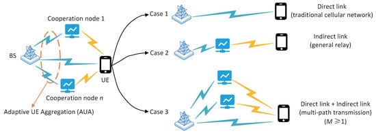
Figure 1.
System model.
Moreover, it is important to select a better cooperation node for performance optimization. An appropriate cooperation node will improve the reliability of the whole system and decrease the latency, which provides a better experience for the UE. The authors of in [28] proposed a cooperation node path selection scheme based on a convolutional neural network (CNN), and the authors of [29] proposed supervised machine learning techniques and a prototype framework for further investigation. These schemes can dynamically select the optimal cooperation node according to the real-time situation of the network, thereby improving the reliability and latency performance of the network. Another piece of research [30] is about a cooperation node selection scheme based on mobile edge computing (MEC), which can use edge computing resources to optimize the selection of cooperation nodes. One of the sink nodes is static and another is mobile in this study. In addition, URLLC technology based on multi-path selection and scheduling can choose the optimal path for data transmission according to the load and bandwidth of the network [31]. In this work, a linear packet-level coding scheme is used for protecting data packets. The optimal packet distribution follows a special “delay-equalized” structure, and this paper proposes a fast bisection scheme to find the optimal packet allocation and code rate.
As far as the radio access network (RAN) is concerned, the multi-armed bandit (MAB) [32] approach represents an ideal solution for considering URLLC allocation of resources in IIoT environments in the case of periodic and aperiodic traffic and even in densely populated networks and offensive traffic. It is a distributed, user-centric approach based on machine learning, where the UE autonomously selects its uplink radio resources without waiting for scheduling grants or connection preconfiguration [33]. In order to decrease the latency between devices, semi-persistent scheduling outperforms the benchmark scheme and provides an end-to-end (E2E) latency below 1 ms, thereby representing a desirable solution for allocating resources for URLLC [16].
A wireless personal area network (WPAN) refers to a network for short-range ad hoc connections between portable consumer appliances and communication devices. The coverage area of a WPAN is generally within a radius of 10 m, which is smaller than that of a wireless local area network (LAN). The ad hoc connection contains two core evaluation indicators: one refers to the ability of the device to undertake both the main control function and the controlled function, and the other refers to the convenience of the device joining or leaving the existing network [34]. For the portable devices of a short-range WPAN, a smart plug hub (SPH) architecture for real-time measurement of the activities of daily living (ADL) can accomplish this task to some extent. This architecture overcomes the problems of low accuracy and privacy violation through sensor fusion and device collaboration [35]. Some researchers have found that using smart mirrors and biological information to perform device cooperation has higher accuracy in predicting user actions [36]. In addition, the selection of cooperation nodes is important for system communication. By using a fuzzy logic decision-making method, the BS can select the “best cooperation node” based on various criteria, which are cooperation node selection, the cooperation node’s SNR and SER, the cooperation node’s reputation, cooperation node strategy, and cooperation node location criteria. At the same time, the cooperation node can also use different strategies for transmission, which are the decode-and-forward strategy (DF), amplify-and-forward strategy (AF), and compress-and-forward strategy (CF) [37]. Based on the channel state information (CSI) of each cooperation node, using adaptive cooperation node selection strategies can minimize the system outage probability (SOP). It was indicated that AF cooperation nodes have been shown to be better than DF cooperation nodes in [38].
Although this single-path communication is widely used, it is difficult to satisfy or meet the latest requirements of 5G in terms of stability, reliability, and latency with it. The short-term feasibility and complexity of the above methods are not suitable for some scenarios. In order to continue the research of R16, the idea of UE aggregation has been proposed [21,39]. From the original single-path transmitting information to the current multi-path sending information at the same time, obviously, in comparison, the transmission rate is much higher than before, and stability is guaranteed to a certain extent [13].
3. System Model and Detail Design
In this paper, the proposed scheme is named AUA transmission, which is shown in the left part of Figure 1, and such a scheme can be changed to three cases according to different situations (right part of Figure 1):
- Case 1 represents the current traditional cellular network, wherein the UE transmits (or receives) data directly to (or from) the BS without help from any cooperation node. There are no other cooperation nodes to assist the UE, and there is only one direct link between the BS and UE. Correspondingly, it is hard to guarantee the data rate or latency under such single-path transmission when the UE is far away from the BS.
- Case 2 is also named general relay, which is similar to a traditional relay network. In this case, the BS will balance the transmission number of direct links and indirect links and choose the link that can obtain lower latency or better coverage. In this paper, it is assumed that the BS does not perform reception of UE data when the UE transmits data to the relay or coordination node. This means there is no combination at the BS across different source nodes for a single packet. For easy description, this scheme is also named Case 2 without (wo) combination. Some descriptions of the general relay are summarized in Section 3.1. Similar to Case 1, such transmission is also single-path based, and it uses an indirect path between the UE and BS in Case 2.
- Case 3 explores the diversity gain or power boosting by aggregating multiple cooperation nodes to forward UE data, and the BS could combine the received data to improve transmission reliability. Different from Case 1 and Case 2, there are multiple simultaneous radio links in Case 3 (i.e., the transmission in Case 3 is multi-path based). Assuming there are cooperation nodes, the path number would be , corresponding to the direct path between the UE and BS, and M indirect paths between the UE and BS via cooperation nodes. Such a transmission scheme is named UE aggregation-based transmission, since the cooperation nodes in this paper can be normal UEs. Moreover, the link condition over different paths would vary over time, and it is natural to select appropriate paths for energy consumption efficiency without transmission reliability or latency loss. Then, the detailed theoretical analysis of fixed multi-path-based transmission (Case 3 non-AUA) and the proposed adaptive UE aggregation for multi-path-based transmission (Case 3 AUA) is described in Section 3.3.
Without a doubt, the detailed transmission for different UEs can switch among these three cases according to the real transmission environments or requirements. Under the proposed AUA scheme, there are three different links: a link between the UE and cooperation node (UC link), a link between the UE and BS (UB link), and a link between the cooperation node and BS (CB link). In this work, a composite channel model is considered, and the signal-to-noise ratio (SNR) is used to reflect the quality of the link, which is depicted as follows [40]:
where g represents the fast channel fading and follows a Nakagami distribution. It can be known that is distributed according to a gamma distribution, while represents the shadowing effect and is modeled by a log-normal distribution. In addition, is the path loss of the channel, is the signal transmit power, and the system has Gaussian random noise with zero mean and variance .
The following part of this section elaborates on the three system models and provides a detailed design of each model. These models have been developed to address specific communication challenges and optimize system performance. The design considerations take into account various factors such as latency consumption, energy consumption, spectrum efficiency, throughput, and coverage.
3.1. General Relay
The name general relay corresponds to the previously mentioned Case 2 wo combination. In 2020, the 3GPP R16 standard was frozen, marking the emergence of the 5G era in response to the demands of the time [41]. LTE D2D has been replaced by NR sidelink, and the development of sidelink has reached a new stage. The foundation of 5G enables a broader range of applications for NR sidelink, which in turn facilitates the realization of advanced automation application cases [42]. In 2022, the 3GPP R17 standard was finally frozen [43], which introduced NR sidelink cooperation node work items and research topics. The NR sidelink cooperation node, as an extension of NR sidelink, expands the network coverage and opens up new possibilities for communication between devices [44].
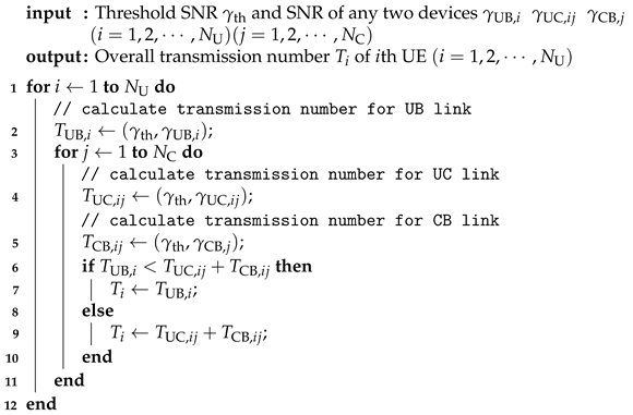
In traditional communication, when a cooperation node assists UE in sending a message, the BS only receives data from the cooperation node. During this process, the data that the UE broadcasts is not processed by the BS. This mode of operation is known as general relay and serves as the benchmark for our simulations by default. The overall transmission numbers for each piece of UE in a direct link and indirect link are calculated at first. Then, the system compares the overall number of transmissions in these two links and sends control signals to allow the UE to choose the link that ultimately requires fewer transmissions, thereby reducing the latency. The pseudocode of general relay is shown as Algorithm 1.
| Algorithm 1: General relay. |
 |
3.2. Case 2 with the Combination
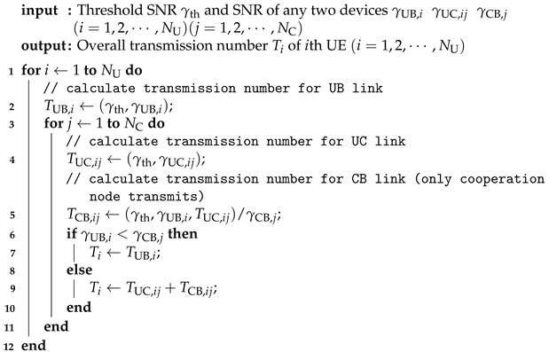
Case 2 with the combination scheme is determined by the amount of information currently being sent by the UE and received by the BS. Each time the UE retransmits, the BS evaluates whether it is more advantageous to forward the data through the cooperation node or retransmit them directly. Since the outcome of each transmission cannot be predicted in advance, it becomes challenging for the BS to preschedule resources. Moreover, allocating additional resources for intermediate operations to calculate case selection becomes necessary. This scheme can reduce the overall energy consumption to some extent. However, it may not optimize the system’s latency to a significant degree. The pseudocode of Case 2 with the combination is shown as Algorithm 2.
| Algorithm 2: Case 2 with combination. |
 |
3.3. Adaptive UE Aggregation
By combining Case 2 with the combination scheme with UE aggregation, the integration of UE transmission and cooperation nodes become more effective, and this is called the multi-path transmission scheme. In this case, the BS can determine whether it is more advantageous to transmit data through both the cooperation nodes and UE or solely through the UE based on their positions. This approach saves resources and eliminates the need for intermediate calculations. While this scheme can reduce latency to a certain extent, it increases the overall energy consumption of the system. The system model of the multi-path transmission scheme is Case 3 in Figure 1.
Furthermore, the main idea of AUA is based on single-path transmission and multi-path transmission schemes. On the one hand, it is certain that the latency of the system under a multi-path transmission scheme is less than that of a single-path transmission scheme. On the other hand, the overall energy consumption of the system in a multi-path transmission scheme is greater than that under a single-path transmission scheme. In other words, if the UE is far away from the BS compared with the cooperation node, then this means that the SNR between the UE and BS () is very small compared with the SNR between the cooperation node and BS (). In this case, there is no need to send information to the UE because the contribution of the UE is negligible. Similarly, if the cooperation node is far away from the BS compared with the UE, then this means that the SNR between the cooperation node and BS () is quite small compared with the SNR between the UE and BS (). In this case, there is no need to send information to the cooperation node because the contribution of the cooperation node is negligible.
Based on this consideration, we propose two proportional coefficients (in dB) and (in dB) to specify that the UE chooses the transmission scheme. To be clear, the flowcharts of the UE aggregation and adaptive UE aggregation scheme are shown in Figure 2. First of all, it is necessary to determine whether the location of the UE is close to the BS. If it is close, then there is no need to assist transmission through the cooperation nodes. Then, the SNR between any two devices can be calculated using Equation (1). After finishing the relative parameters, if the effect of the cooperation node is tiny, then the direct link is chosen in this situation. This can be distinguished by the following equation:
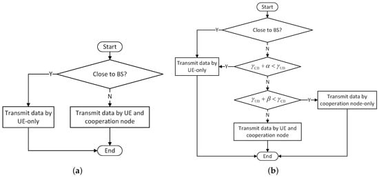
Figure 2.
The flowcharts. (a) UE aggregation. (b) Adaptive UE aggregation.
If the effect of the UE is tiny, then the indirect link is chosen in this situation. This can be distinguished by the following equation:
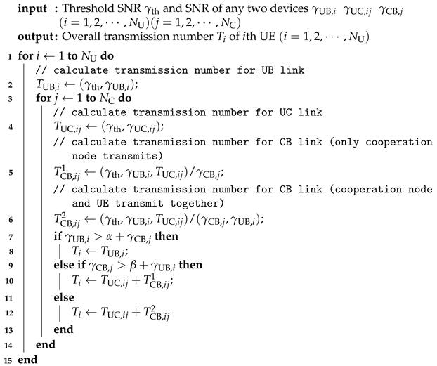
Moreover, the other UEs that do not satisfy the above two inequalities will choose Case 3, in which the UE and cooperation nodes transmit information at the same time. The pseudocode of Case 2 with the combination is shown as Algorithm 3.
| Algorithm 3: Adaptive UE aggregation. |
 |
4. Simulation Results, Theoretical Calculation, and Analysis
4.1. Performance Comparison under Different Transmission Schemes
Unless otherwise specified, the relevant parameters of the simulation model are shown in Table 2. In addition, in order to complete the experiment successfully, we made the following assumptions:
Table 2.
Simulation settings.
- pieces of UE are randomly distributed within the region from 0 to R.
- cooperation nodes are evenly distributed around R/2.
- There is no interference between any two devices.
Under these conditions, in order to compare the latency performance of AUA under different and values compared with general relay, we set 2 dB, 3 dB, 4 dB, and 6 dB. The cumulative distribution function (CDF) of the SNR between the UE and BS is shown in Figure 3. It can be noticed that the SNR between the UE and BS at 90% was below 6.2 dB. In order to test the effectiveness of AUA, we set the SNR threshold higher to obtain better performance when there were more transmissions.
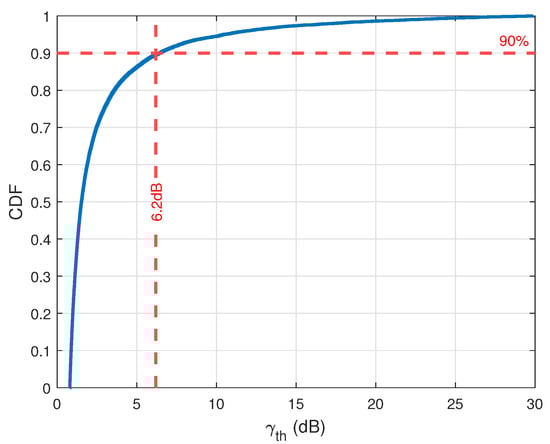
Figure 3.
CDF of SNR between UE and BS.
Furthermore, we assumed that the path loss calculation for the UE located between 0 and was identical to the path loss calculation for the UE situated at . This assumption implies that there is no variation in the path loss experienced by the UE within the first 1% of the total radius compared with the UE precisely located at . In other words, the propagation characteristics, such as the signal attenuation and interference levels, remained consistent within this specific range.
Our first concern was the latency problem of the whole system, which is the overall transmission number of the whole system. In comparison with a general relay configuration, we computed the latency performance gains for Case 2 with the combination, multi-path transmission, and AUA schemes. Figure 4 displays the gains of different schemes when the cooperation nodes were located at , , and . As shown in Figure 4b, it is certain that the latency performance of Case 2 with the combination scheme is the lower bound, which is the same as the AUA scheme when dB. The performance of the multi-path transmission scheme is the upper bound, which is the same as the AUA scheme when . Actually, the gain of the AUA scheme when dB was almost the same as that of the multi-path transmission scheme. In addition, the number of transmissions from the cooperation node to the BS had a great influence on the gain value. Whenever the number of transmissions from the cooperation node to the BS increased, the gain value under would suddenly drop and then return to the normal level. However, when analyzed with Figure 4a,c, the values of and for reaching the maximum performance gradually decreased as the distance between the cooperation node and the BS increased.
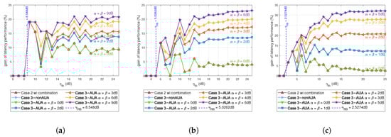
Figure 4.
The gain of latency performance vs. under different schemes ( = 1). (a) Cooperation node location: R/3. (b) Cooperation node location: R/2. (c) Cooperation node location: 2R/3.
Moreover, the CDF of the latency enhancement gain under different and values is shown in Figure 5:
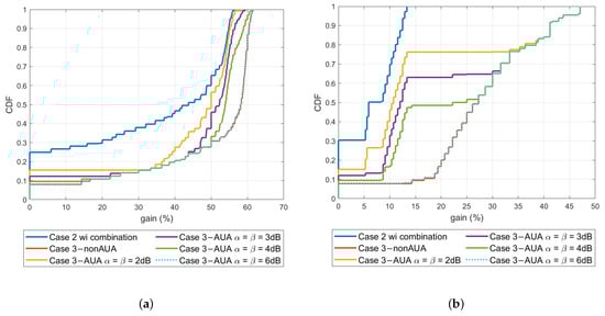
Figure 5.
CDF of latency enhancement gain under different schemes ( = 1). (a) Benchmark: Case 1 (traditional cellular network). (b) Benchmark: Case 2 (traditional relay network).
- If the benchmark of the simulation was the traditional cellular network (Case 1), then the CDF of the latency enhancement gain under different and values (Figure 5a) showed that most of the UE had a large gain. Due to the lack of cooperation node assistance, the latency of the no cooperation node scenario differed from other schemes when the threshold SNR was at a lower level. At the same time, more UE needed to transmit more times before the BS could successfully decode the data. Therefore, the schemes mentioned earlier had more UE with higher latency gain in the obtained CDF curve.
- If the benchmark of the simulation was the traditional relay network (Case 2 wo combination), then the CDF of the latency enhancement gain under different and values (Figure 5b) indicated that the assistance of cooperation nodes could reduce latency, and thus the increase in the final result was less than the previous one. With the increment of and , more UE in the cell chose the multi-path transmission scheme for information transmission. Therefore, there was more UE with higher gain of latency performance.
Furthermore, Figure 6 exhibits the gain of different distances under Case 2 with the combination, multi-path transmission, and AUA schemes when dB and dB. With the increase in and , more and more UE in the cell switched from Case 2 with the combination scheme to the multi-path transmission scheme. This range continued to spread from the cooperation nodes’ positions to the ends.
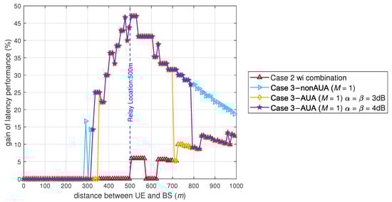
Figure 6.
The gain of latency performance vs. distance under different schemes.
However, although the larger values of and could result in better latency performance, the performance of energy consumption was quite terrible as the values of and increased, as shown in Figure 7. Therefore, a suitable measurement standard is required to measure the performance of the whole system, which will be discussed in the next section.
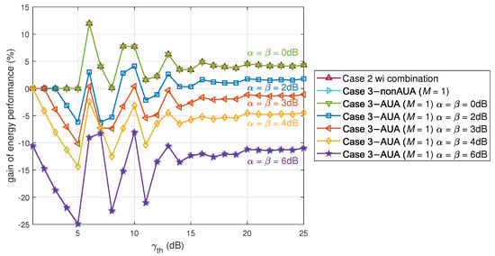
Figure 7.
The gain of energy performance vs. under different schemes (R/2).
4.2. EDP Evaluation among Different Transmission Schemes
In order to further discuss and compare the performance of different schemes, we separately calculated the information transmission process of UE with different distances from the BS and then further analyzed the latency performance and energy consumption performance at different locations. In addition, in this paper, the judging criterion was set as the energy-delay product (EDP) to represent the performance of different schemes, especially when comparing the performance of different and values. The EDP is simply the multiplication of the energy consumption and latency profiles for each case [45], and it is a useful metric for comparing the speed of energy-efficient communication [46].
Figure 8 displays the measurement standards of the general relay scheme and Case 2 with the combination scheme, multi-path transmission scheme, and adaptive UE aggregation scheme, including the overall energy consumption, overall latency, and EDP.
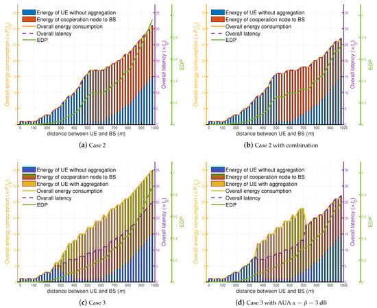
Figure 8.
The measurement standards of different schemes.
Figure 8a presents the measurement standards of the general relay scheme, which consisted of two steps: the UE broadcasting to the cooperation node without aggregation and the cooperation node transmitting to the BS. In the traditional cooperation node network, the UE that required cooperation node assistance transmitted more times than other schemes due to this scheme not having the combination.
Figure 8b depicts the measurement standards of Case 2 with the combination scheme. This scheme also involves two steps: the UE broadcasting to both the BS and the cooperation node without aggregation followed by the cooperation node transmitting to the BS, similar to the general relay scheme. The difference is that this scheme has the combination. This kind of scheme may cost a lot of time when transmitting information, but it can save energy consumption to some extent.
Figure 8c presents the measurement standards of the multi-path transmission scheme. This approach comprises three stages: the UE broadcasting to both the BS and the cooperation node without aggregation, the cooperation node transmitting to the BS, and the UE transmitting to the BS with aggregation after the cooperation node received the data from the UE. In this situation, the primary advantage of this scheme is its ability to minimize latency, as it selects the shortest latency among the three available schemes. However, it is important to note that the efficiency at reducing latency comes at the cost of increased energy consumption. Although it effectively addresses the issue of latency, it also results in higher energy expenditure.
In the AUA scheme, with the setting of and being equal to 3 dB, there were also three steps involved. These steps included the UE broadcasting to both the BS and the cooperation nodes without aggregation, the cooperation nodes transmitting to the BS, and finally the UE transmitting to the BS with aggregation after the cooperation nodes received the data from the UE, similar to the multi-path transmission scheme. Figure 8d illustrates the energy consumption of these three steps, as well as the overall energy consumption, overall latency, and EDP for the AUA scheme. The main difference between the AUA scheme and multi-path transmission scheme is that not every UE chooses aggregation transmission. It can dynamically select a range of UE transmitting data with a single path and others transmitting data with multiple paths.
Based on the information provided in the previous figures, we summarized the overall latency, overall energy consumption, and EDP values for the different schemes. The comparison is presented in Figure 9a for the overall latency, Figure 9b for the overall energy consumption, and Figure 9c for the EDP. First, it is obvious that Case 2 with the combination scheme cost less energy than that of the multi-path transmission scheme when the UE was far away from the BS. Secondly, it is certain that the BS took less time to decode the UE information if the UE chose multi-path transmission instead of Case 2 with the combination scheme when the UE was far away from the BS. Lastly, the AUA scheme would balance these two kinds of schemes, which had better performance for the EDP when and were equal to 3 dB. We can notice that the vast majority of users will choose the case where the EDP is smaller. From this perspective, AUA balances the performance of energy and latency, making it a win-win overall. However, dB are not the best and values in this situation. The following part discusses the calculation of the optimal and values in different situations.
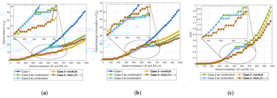
Figure 9.
The performance critical values vs. distance under different schemes. (a) Latency performance. (b) Energy performance. (c) EDP.
4.3. Theoretical Calculation and Simulation of and
In order to optimize the EDP of the whole system, the calculation of energy consumption and latency plays an important role in the whole simulation, and this is expressed in the following equations:
where represents the overall energy consumption when the BS successfully decodes the data of the ith UE, represents the overall latency when the BS successfully decodes the data of the ith UE, is the transmission number of the ith UE data successfully decoded at the jth cooperation node, is the transmission number of the ith UE transmitting to the BS without cooperation node assistance, is the transmission number of the jth cooperation node assisting the ith UE to the BS, represents the energy-delay product of the ith UE, is the unit of transmission power, and is the unit of time. In addition, we have
where represents the transmission number of the UE to the cooperation node if the cooperation node assists, represents the transmission number of the UE to the BS if the cooperation node does not assist, represents the transmission number of the UE and cooperation node to the BS after the cooperation node successfully decodes the data and prepares to assist the UE, is the EDP of Case 2 with the combination scheme, and is the EDP of the multi-path transmission scheme.
In order to find out the best here, the value of must be less than ; that is, . When the simulation settings were as displayed in Table 2, we could calculate the distance between the UE and BS to be m. The value of was dB under the current simulation settings:
where represents the transmission number of the cooperation node to the BS after the cooperation node received data and assisted the UE, is the EDP of Case 2 with the combination scheme, and is the EDP of the multi-path transmission scheme.
In order to find out the best value here, the value of must less than ; that is, . When the simulation settings were as displayed in Table 2, we could calculate the distance between the UE and BS to be m. The value of was dB under the current simulation setting.
After analyzing the optional and values when the simulation settings were as displayed in Table 2, we calculated the optional and values when the cooperation node was at different positions and different . Table 3 and Table 4 represent the best and values when the cooperation node position was at and , respectively.
Table 3.
and for different . Cooperation node location: R/2.
Table 4.
and for different . Cooperation node location: R/3.
4.4. Multi-Path Design () and Simulation Results
In the case of multi-path transmission under the AUA scheme, we set a parameter M in the system to limit the maximum number of simultaneous transmissions for the cooperation node. Parameter k represents the transmission times (). Multiple cooperation nodes or UE transmitting at the same time was counted as one time. Supposing that there were cooperation nodes in the cell, the angle () between the UE and the farthest cooperation node that successfully decoded the UE data in the direction of the BS at the kth time unit could be expressed as
where r is the distance between the cooperation node and BS, is the distance between the ith UE and BS, and is the maximum radius that can be covered when the ith UE transmits k times. This means that of the cooperation nodes successfully decoded the UE’s information after the kth transmission of the UE, and then these cooperation nodes could assist in the next time unit (). Meanwhile, can be expressed as
In order to realize the effect of the multi-path scheme, we introduced three regulators to accomplish this task, which are p, q, and . These three regulators can calculate the number of assisted transmission cooperation nodes for each transmission time, whether the cooperation node assists, and whether the UE stops transmitting at this time:
where is the information that the base station has already decoded, is the amount of new successfully decoded cooperation nodes at the jth time unit, is used to dynamically select the number of cooperation nodes for each new assistance cooperation node, and and represent whether the cooperation node assists the UE in sending information at the ith time unit and whether the UE needs to reserve energy and not send information in this time unit, respectively.
Through the aforementioned and , the UE with a cell can be divided into three groups: UE-only transmission, UE aggregation, and cooperation node-only transmission, which is the main idea of adaptive UE aggregation. If user equipment is located in a UE-only transmission area, then just set , and . When the position of the user equipment is close to the cooperation node, the more cooperation nodes assist, the lower the delay will become. However, the maximum number of simultaneous assisted cooperation nodes can be set in the system, which is denoted by M. In this case, M cooperation nodes decode the information successfully when the ith UE transmits times (), which means that M cooperation nodes can assist the UE to transmit data at . The corresponding regulators can be defined as , and is defined as in Equation (15). Moreover, if the location of the UE is far away from the BS, then there is no need for the UE to transmit information when enough cooperation nodes can assist it. This can save energy for the specified UE. In this case, the corresponding regulators can be defined as . After that, the overall energy consumption and overall latency can be expressed as in Equations (16) and (17):
According to Section 4.3, the values of and were set to be 3 dB in this subsection. The simulation results are shown in Figure 10. Naturally, we could find that the latency decreased as the maximum transmission equipment increased. However, the increasing rate of the overall latency gain kept decreasing because this was limited by the overall number of cooperation nodes () in the entire cell.
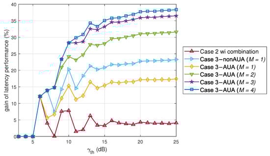
Figure 10.
The latency performance gain of different schemes (R/2, AUA with dB).
In summary, the analysis results have been conveniently compiled in Table 5. Notably, when considering Case 2 without the combination as the benchmark, simulating the latency and energy performance for Case 1 became unnecessary. Moreover, as the maximum number of assisted nodes increased, the system network demonstrated improved latency performance, consequently leading to enhanced URLLC capabilities. This enhancement in URLLC performance holds significant promise for meeting the demanding requirements of critical applications. In addition, in this article, we did not consider the impact of interference on the UE, and the time of each transmission was assumed to be fixed. The final result may have been inaccurate, but the basic trend was correct.
Table 5.
Summary of latency performance gain and energy consumption gain under different schemes.
The overall latency and overall energy consumption would change with the differences in M. Figure 11a,b show the overall latency and overall energy consumption of different distances under . The closer the UE was to the cooperation node, the lower the overall latency. The curve for the latency is easier to understand, but the curve for energy consumption is more complicated. It can be clearly seen that there is a phenomenon of jitter in the figure. Because users who are closer to each other may have the same overall number of transmissions (the same overall latency), the successful decoding time of the jth cooperation node may be different, resulting in users who are closer to the base station possibly consuming more energy. In addition, if the last transmission does not require M cooperation nodes to assist in the transmission for successful decoding, then there will be energy loss. Both of these two aspects can lead to fluctuations in the curves.
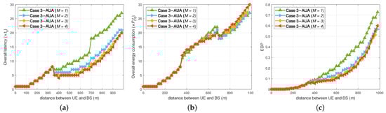
Figure 11.
The performance critical values vs. distance under multi-path AUA with different cooperation numbers ( dB). (a) Latency performance. (b) Energy performance. (c) EDP.
5. Conclusions
In this paper, we proposed a new method based on UE aggregation which is called adaptive UE aggregation. With the support of the evaluation standard of the EDP, this new scheme can optimize energy consumption and latency jointly under different scenarios, which is much better than traditional cellular networks and traditional relay networks. In addition, when the number of cooperation nodes for a specified UE increases, using the AUA scheme can provide better performance, which can greatly reduce latency and prevent unnecessary energy waste. However, the shortcomings of the centralized system are quite serious. The central node may become a bottleneck if an accident occurs on the central node side, and then the entire system may be unavailable. As the amount of UE increases, this situation will be more obvious.
In future work, the distributed systems and consensus mechanism will be embedded into the speculative parallelization to further secure the transmission process and improve the reliability and performance of the whole system. Furthermore, the impact of potential security, which would be a higher-layer issue, and the interference composed of multiple users and multiple cells will be considered in future work.
Author Contributions
Conceptualization, H.C., R.F. and T.C.; methodology, H.C. and R.F.; software, H.C. and R.F.; validation, H.C. and R.F.; formal analysis, H.C. and R.F.; investigation, H.C. and R.F.; resources, H.C., R.F. and T.C.; data curation, H.C. and R.F.; writing—original draft preparation, H.C. and R.F.; writing—review and editing, H.C. and R.F.; visualization, H.C. and R.F.; supervision, H.C., R.F., T.C., P.W., Z.W., S.L. and F.L.; project administration, H.C. and R.F. All authors have read and agreed to the published version of the manuscript.
Funding
This paper was supported by BJUT Project 40042001202218 and the National Key Research and Development Program of China (2020YFF0305401).
Institutional Review Board Statement
Not applicable.
Informed Consent Statement
Not applicable.
Data Availability Statement
Not applicable.
Conflicts of Interest
The authors declare no conflict of interest.
Abbreviations
The following abbreviations are used in this manuscript:
| 3GPP | The Third Generation Partnership Project |
| ADL | Activities of daily living |
| AF | Amplify-and-forward |
| AGVs | Automated guided vehicles |
| AUA | Adaptive UE aggregation |
| BLE | Bluetooth low energy |
| CDF | Cumulative distribution function |
| CF | Compress-and-forward |
| CSI | Channel state information |
| D2D | Device-to-device |
| DL | Downlink |
| EDP | Energy-delay product |
| E2E | End-to-end |
| IoT | Internet of Things |
| IIoT | Industry Internet of Things |
| LAN | Local area network |
| MAB | Multi-armed bandit |
| MEC | Mobile edge computing |
| MIMO | Multiple-input multiple-output |
| RAN | Radio access network |
| RedCap | Reduced capability |
| SNR | Signal-to-noise ratio |
| SOP | System outage probability |
| SPH | Smart plug hub |
| UAVs | Unmanned aerial vehicles |
| UE | User equipment |
| UL | Uplink |
| URLLC | Ultra-reliable low-latency communication |
| WPAN | Wireless personal area network |
References
- Wollschlaeger, M.; Sauter, T.; Jasperneite, J. The Future of Industrial Communication: Automation Networks in the Era of the Internet of Things and Industry 4.0. IEEE Ind. Electron. Mag. 2017, 11, 17–27. [Google Scholar] [CrossRef]
- Kumar, S.; Chandra, S.K.; Shukla, R.N.; Panigrahi, L. Industry 4.0 based Machine Learning Models for Anomalous Product Detection and Classification. In Proceedings of the 2022 OPJU International Technology Conference on Emerging Technologies for Sustainable Development (OTCON), Raigarh, Chhattisgarh, India, 8–10 February 2023; pp. 1–6. [Google Scholar]
- Aazam, M.; Zeadally, S.; Harras, K.A. Deploying Fog Computing in Industrial Internet of Things and Industry 4.0. IEEE Trans. Ind. Inform. 2018, 14, 4674–4682. [Google Scholar] [CrossRef]
- Kada, B.; Alzubairi, A.; Tameem, A. Industrial Communication Networks and the Future of Industrial Automation. In Proceedings of the 2019 Industrial & Systems Engineering Conference (ISEC), Jeddah, Saudi Arabia, 19–20 January 2019; pp. 1–5. [Google Scholar]
- Liu, W.; Nair, G.; Li, Y.; Nesic, D.; Vucetic, B.; Poor, H.V. On the Latency, Rate, and Reliability Tradeoff in Wireless Networked Control Systems for IIoT. IEEE Internet Things J. 2021, 8, 723–733. [Google Scholar] [CrossRef]
- Wang, X. 5G-Advanced: The Only Way to Evolve from 5G to 6G. ZTE Technology. 2021. Available online: https://www.zte.com.cn/china/about/magazine/zte-technologies/2021/8-cn/3/1.html (accessed on 22 April 2023).
- Franchi, F.; Marotta, A.; Rinaldi, C.; Graziosi, F.; D’Errico, L. IoT-based Disaster Management System on 5G uRLLC Network. In Proceedings of the 2019 International Conference on Information and Communication Technologies for Disaster Management (ICT-DM), Paris, France, 18–20 December 2019; pp. 1–4. [Google Scholar]
- Cheng, J.; Chen, W.; Tao, F.; Lin, C.-L. Industrial IoT in 5G environment towards smart manufacturing. J. Ind. Inf. Integr. 2018, 10, 10–19. [Google Scholar]
- 5G-ACIA. 5G for Industrial Internet of Things (IIoT): Capabilities, Features, and Potential. 2021. Available online: https://5g-acia.org/whitepapers/5g-for-industrial-internet-of-things/ (accessed on 23 April 2023).
- ITU-R, Report M.2516-0. Future Technology Trends of Terrestrial International Mobile Telecommunications Systems towards 2030 and beyond. 2022. Available online: https://www.itu.int/dms_pub/itu-r/opb/rep/R-REP-M.2516-2022-PDF-E.pdf (accessed on 23 July 2023).
- 3GPP, TS 38.825. Study on NR Industrial Internet of Things (IoT) (Release 16). 2019. Available online: https://portal.3gpp.org/desktopmodules/Specifications/SpecificationDetails.aspx?specificationId=3492 (accessed on 23 April 2023).
- Khan, B.S.; Jangsher, S.; Ahmed, A.; Al-Dweik, A. URLLC and eMBB in 5G Industrial IoT: A Survey. IEEE Open J. Commun. Soc. 2022, 3, 1134–1163. [Google Scholar] [CrossRef]
- Al-Jarrah, M.A.; Yaseen, M.A.; Al-Dweik, A.; Dobre, O.A.; Alsusa, E. Decision Fusion for IoT-Based Wireless Sensor Networks. IEEE Internet Things J. 2020, 7, 1313–1326. [Google Scholar]
- Ahmed, A.; Naeem, M.; Al-Dweik, A. Joint Optimization of Sensors Association and UAVs Placement in IoT Applications with Practical Network Constraints. IEEE Access 2021, 9, 7674–7689. [Google Scholar] [CrossRef]
- Al-Dweik, A.; Muresan, R.; Mayhew, M.; Lieberman, M. IoT-based multifunctional Scalable real-time Enhanced Road Side Unit for Intelligent Transportation Systems. In Proceedings of the 2017 IEEE 30th Canadian Conference on Electrical and Computer Engineering (CCECE), Windsor, ON, Canada, 30 April–3 May 2017; pp. 1–6. [Google Scholar]
- Cuozzo, G.; Cavallero, S.; Pase, F.; Giordani, M.; Eichinger, J.; Buratti, C.; Verdone, R.; Zorzi, M. Enabling URLLC in 5G NR IIoT Networks: A Full-Stack End-to-End Analysis. In Proceedings of the 2022 Joint European Conference on Networks and Communications & 6G Summit (EuCNC/6G Summit), Grenoble, France, 7–10 June 2022; pp. 333–338. [Google Scholar]
- Moloudi, S.; Mozaffari, M.; Veedu, S.N.K.; Kittichokechai, K.; Wang, Y.-P.E.; Bergman, J.; Höglund, A. Coverage Evaluation for 5G Reduced Capability New Radio (NR-RedCap). IEEE Access 2021, 9, 45055–45067. [Google Scholar] [CrossRef]
- Saafi, S.; Vikhrova, O.; Andreev, S.; Hosek, J. Enhancing Uplink Performance of NR RedCap in Industrial 5G/B5G Systems. In Proceedings of the 2022 IEEE International Conference on Communications Workshops (ICC Workshops), Seoul, Republic of Korea, 16–20 May 2022; pp. 520–525. [Google Scholar]
- Wang, C.; Zhu, X.; Jiang, Y.; Zeng, H.; Zheng, F.-C. Fairness-Aware Closed-Form UL-DL Power Allocation for NOMA in UL Heavy UAV Systems. In Proceedings of the 2021 IEEE Global Communications Conference (GLOBECOM), Madrid, Spain, 7–11 December 2021; pp. 1–6. [Google Scholar]
- Vivo. Study on UE Aggregation for Industry with Multi-Connectivity. 2021. Available online: https://www.3gpp.org/ftp/tsg_sa/WG2_Arch/TSGS2_146E_Electronic_2021-08/INBOX/DRAFTS/UE%20Aggregation%20for%20Industry%20with%20Multi-connectivity.pdf (accessed on 23 April 2023).
- NEC. Summary of 3GPP TSG RAN Rel-18 Workshop. 2021. Available online: https://global5g.org/sites/default/files/Summary%20of%20RAN%20Rel-18%20Workshop%20for%205G-IA%20Pre-STD%20WG%20%28H.%20van%20der%20Veen%20NEC%29.pdf (accessed on 23 April 2023).
- China Mobile. Motivation of Study for UE Aggregation. 3GPP TSG RAN Rel-18 Workshop, RWS-210355. 28 June 2021–2 July 2021. Available online: https://www.3gpp.org/ftp/tsg_sa/WG2_Arch/TSGS2_146E_Electronic_2021-08/INBOX/DRAFTS/UE%20Aggregation%20for%20Industry%20with%20Multi-connectivity.pdf (accessed on 24 April 2023).
- Wang, J.; Ma, J.; Li, Y.; Liu, X. D2D Communication Relay Selection Strategy Based on Two-hop Social Relationship. In Proceedings of the 2021 IEEE 4th International Conference on Electronic Information and Communication Technology (ICEICT), Xi’an, China, 18–20 August 2021; pp. 592–595. [Google Scholar]
- Kim, M.; Jang, J.-w. A Study on Implementation of Multi-hop Network for LoRaWAN Communication. In Proceedings of the 2020 International Conference on Information Networking (ICOIN), Barcelona, Spain, 7–10 January 2020; pp. 553–555. [Google Scholar]
- Harounabadi, M.; Soleymani, D.M.; Bhadauria, S.; Leyh, M.; Roth-Mandutz, E. V2X in 3GPP Standardization: NR Sidelink in Rel-16 and Beyond. IEEE Commun. Stand. Mag. 2021, 5, 12–21. [Google Scholar] [CrossRef]
- Etxaniz, J.; Aranguren, G. Modeling of the Data Transportation Network of a Multi-Hop Data-Content-Sharing Home Network. IEEE Trans. 2015, 61, 31–38. [Google Scholar] [CrossRef]
- Yu, C.; Lin, E. Reliable Formation Protocol for Bluetooth Hybrid Single-hop and Multi-hop Networks. IEEE Netw. 2017, 32, 120–125. [Google Scholar] [CrossRef]
- Liu, F.; Wang, Y.; Li, H. Physical Layer Security of Cooperative Network with Machine Learning-based relay Selection. In Proceedings of the 2019 IEEE 6th International Symposium on Electromagnetic Compatibility (ISEMC), Nanjing, China, 1–4 November 2019; pp. 1–5. [Google Scholar]
- Dang, H.; Liang, Y.; Wei, L.; Li, C.; Dang, S. Enabling Relay Selection in Cooperative Networks by Supervised Machine Learning. In Proceedings of the 2018 Eighth International Conference on Instrumentation & Measurement, Computer, Communication and Control (IMCCC), Harbin, China, 19–21 July 2018; pp. 1459–1463. [Google Scholar]
- Li, X.; Guo, S.; Li, P. Energy-Efficient Data Collection Scheme Based on Mobile Edge Computing in WSNs. In Proceedings of the 2019 15th International Conference on Mobile Ad-Hoc and Sensor Networks (MSN), Shenzhen, China, 11–13 December 2019; pp. 95–100. [Google Scholar]
- Mao, W.; Yeh, S.-P.; Zhu, J.; Nikopour, H.; Talwar, S. Delay-optimal Linear Packet-level Coding for URLLC on Multi-path Wireless Networks. In Proceedings of the 2022 IEEE 33rd Annual International Symposium on Personal, Indoor and Mobile Radio Communications (PIMRC), Kyoto, Japan, 12–15 September 2022; pp. 1171–1177. [Google Scholar]
- Slivkins, A. Introduction to Multi-Armed Bandits; Now Foundations and Trends: Boston, MA, USA, 2019. [Google Scholar]
- Pase, F.; Giordani, M.; Cuozzo, G.; Cavallero, S.; Eichinger, J.; Verdone, R.; Zorzi, M. Distributed Resource Allocation for URLLC in IIoT Scenarios: A Multi-Armed Bandit Approach. In Proceedings of the 2022 IEEE Globecom Workshops (GC Wkshps), Rio de Janeiro, Brazil, 4–8 December 2022; pp. 383–388. [Google Scholar]
- Zhu, X.; Jin, H.; Feng, C.; Hu, Y.; Feng, Z. Modern Communication Foundation and Technology; People’s Posts and Telecommunications Press: Beijing, China, 2004; pp. 354–355. [Google Scholar]
- Kang, H.; Kang, S. Sensor Fusion and Device Collaboration based Smart Plug Hub Architecture for Precise Identification of ADL in Real-Time. In Proceedings of the 2022 IEEE Symposium on Computers and Communications (ISCC), Rhodes, Greece, 30 June–3 July 2022; pp. 1–7. [Google Scholar]
- Ikeuchi, N.; Sakai, E.; Suzuki, H. A Proposal of IoT Device Cooperation System Using Smart Mirror and Biological Information. In Proceedings of the 2020 IEEE 9th Global Conference on Consumer Electronics (GCCE), Kobe, Japan, 13–16 October 2020; pp. 246–247. [Google Scholar]
- Razeghi, B.; Hatamian, M.; Naghizadeh, A.; Sabeti, S.; Hodtani, G.A. A novel relay selection scheme for multi-user cooperation communications using fuzzy logic. In Proceedings of the 2015 IEEE 12th International Conference on Networking, Sensing and Control, Taipei, Taiwan, 9–11 April 2015; pp. 241–246. [Google Scholar]
- Li, G.; Mishra, D.; Hu, Y.; Huang, Y.; Jiang, H. Adaptive Relay Selection Strategies for Cooperative NOMA Networks with User and Relay Cooperation. IEEE Trans. Veh. Technol. 2020, 69, 11728–11742. [Google Scholar] [CrossRef]
- Qualcomm. Setting off the 5G Advanced Evolution. 2022. Available online: https://www.qualcomm.com/content/dam/qcomm-martech/dm-assets/documents/setting-off-the-5g-advanced-evolution-with-3gpp-release-18.pdf (accessed on 23 April 2023).
- Chen, H.-M.; Wang, J.-B.; Chen, M. Downlink outage probability of distributed antenna systems over shadowed Nakagami-m fading channels with antenna selection. In Proceedings of the 2009 International Conference on Wireless Communications & Signal Processing, Nanjing, China, 13–15 November 2009; pp. 1–4. [Google Scholar]
- 3GPP. Release 16. 2020. Available online: https://www.3gpp.org/specifications-technologies/releases/release-16 (accessed on 15 July 2023).
- Lin, X. An Overview of 5G Advanced Evolution in 3GPP Release 18. IEEE Commun. Stand. Mag. 2022, 6, 77–83. [Google Scholar] [CrossRef]
- 3GPP. Release 17. 2022. Available online: https://www.3gpp.org/specifications-technologies/releases/release-17 (accessed on 15 July 2023).
- Chukhno, N.; Orsino, A.; Torsner, J.; Iera, A.; Araniti, G. 5G NR Sidelink Multi-Hop Transmission in Public Safety and Factory Automation Scenarios. IEEE Netw. 2023, in press. [Google Scholar] [CrossRef]
- Ercan, F.; Muhtaroğlu, A. Energy-delay performance of capacitive threshold logic (CTL) circuits for threshold detection. In Proceedings of the 2013 4th Annual International Conference on Energy Aware Computing Systems and Applications (ICEAC), Istanbul, Turkey, 16–18 December 2013; pp. 109–114. [Google Scholar]
- Connor, I.O.; Poittevin, A.; Beux, S.L.; Bosio, A.; Stanojevic, Z.; Baumgartner, O.; Mukherjee, C.; Maneux, C.; Trommer, J.; Mikolajick, T. Analysis of Energy-Delay-Product of a 3D Vertical Nanowire FET Technology. In Proceedings of the 2021 Joint International EUROSOI Workshop and International Conference on Ultimate Integration on Silicon (EuroSOI-ULIS), Caen, France, 1–3 September 2021; pp. 1–4. [Google Scholar]
Disclaimer/Publisher’s Note: The statements, opinions and data contained in all publications are solely those of the individual author(s) and contributor(s) and not of MDPI and/or the editor(s). MDPI and/or the editor(s) disclaim responsibility for any injury to people or property resulting from any ideas, methods, instructions or products referred to in the content. |
© 2023 by the authors. Licensee MDPI, Basel, Switzerland. This article is an open access article distributed under the terms and conditions of the Creative Commons Attribution (CC BY) license (https://creativecommons.org/licenses/by/4.0/).