1. Introduction
Research in the field of honeycomb structures and successful applications in the field of exoskeletons led to the design and testing of elements and parts of exoskeletons used for rehabilitation systems for children. These achievements must satisfy several requirements. First of all, the final project must be able to be made by 3D printers. Moreover, these printers have limitations regarding the dimensions of the parts that can be made in this way.
For the manufacturing process used, the costs are low, primarily due to the price of the raw material (ABS) as well as the production technology and the necessary equipment (incremental technology, 3D printer) [
1,
2,
3].
There are many papers studying different aspects of the 3D printing of the exoskeleton. In the following, we present some significant results concerning the use of this method.
Although many items concerning exoskeletons of the upper limb can be found in the literature, the presented calculations are mainly related to the analysis of the trajectory of movement of individual elements [
4] or the determination of muscle strength [
5]. Many works concern the exoskeletal only in the conceptual phase [
6]. The exoskeletons presented in the papers are more or less complicated systems that force, support, or control movement. As an example, a rehabilitation exoskeleton presented in [
7] can be provided, and also in work [
8], in work [
9], or in work [
10].
Generally, there is no information on the strength calculations of exoskeletal elements. Perhaps such calculations and data exist; however, the authors do not offer such data. The assumptions presented in the works (and drawings) show that the exoskeletons are made of metal elements with high strength parameters. In practice, it is not possible to compare the results of one’s own research with the literature data [
11].
Usable values are mainly related to the strength and stiffness of a given element. Previous research indicates that the structure can be selected in terms of strength (maximum stress) and stiffness (deflection) by controlling the distribution and size of voids (cells) in the structure.
The printers available in the research are the Prusa i3 MK2 in the initial phase and the Prusa i3 MK2S in the final phase of the research. The working space in available printers is 250 × 210 × 200 mm (Prusa i3 MK2) and 250 × 210 × 210 mm (Prusa i3 MK2S), which means that the maximum length of the generated element is 250 mm. For children from a few to 10–12 years, the above conditions are sufficient. Problems with the production of samples of the structure in which the minimum wall thickness was at the level of 1 mm, observed in the initial period, were removed by purchasing a suitable head. Unfortunately, this caused an increase in the time to generate one sample from about 6 h (inaccurate samples) to about 12 h (exact samples).
Another condition is related to the possibility of quickly making changes to the manufactured elements. This is imposed by the rapid growth of children, especially the limbs, which is correlated with the need to correct the shape of the elements during rehabilitation. At the same time, attention is also paid to aesthetic values. The 3D printing technique can produce elements in different colors and the surface of the elements can have a different texture, these being child-friendly structures. Of course, the costs of preparing and manufacturing a particular project can play an important role.
There is an opinion among patients that a prosthesis or medical equipment does not have to reproduce the human body as much as possible. In many cases, patients expressed a desire that the prosthesis had a housing that would be treated as part of the garment, reflecting the character of the person. The choice should strictly depend on the individual patient, but the choice is important. In the case of rehabilitation as well as the use of a prosthesis, well-being can affect the final effects, i.e., benefits or problems in the long run. For children and young people, this perspective can be very long. Neglected injuries and diseases, if they do not have troublesome symptoms in the initial stage, can have very serious effects in adulthood. Factors that seem important for a child are the weight of the device and the external form. In this work, a light and durable structure was sought. For this structure, the technology was sought to offer the possibility of creating a certain internal structure and an external shape customized to a certain patient. For the particular case of children, due to the specificity of their body (growth), it has become important that the technology has the ability to create new elements relatively quickly and cheaply.
2. Materials and Methods: Exoskeletons in Rehabilitation
Specialized literature has shown that by making relatively small changes it is possible to obtain a material with acceptable properties from a qualitative point of view [
12,
13,
14,
15,
16]. As a result, it was decided to change the structure of the honeycombs. The result of this modification consisted of obtaining a new structure, which we called an inverse honeycomb structure.
In this way, the simultaneous elimination of problems related to edge modeling and the establishment of boundary conditions was achieved.
They also tried to model a structure with variable geometry both in length and in height.
In the literature, we can find many articles on the topic of topology optimization in 2D and 3D structures, such as beams, girders, brackets, or other massive support structures [
17,
18,
19,
20]. In the initial project, the initial shape (volume) is full and continuous, but after the study and redesign, the final shape is very similar to a truss structure [
21,
22,
23]. Inspiring existing solutions has allowed them to be adapted to the appropriate conditions.
If a topological optimization of the structure is conducted, a spatial truss structure is obtained, where the elements of the structure obtained have different geometric characteristics (section, length, orientation). Initially, the full structure was modified by introducing holes that change dimensions along the length and height.
In this case, it was possible to produce samples of the developed structure with the required accuracy. As a result, both numerical simulations and experimental tests could be carried out. The obtained results allowed for determining the dependence of strength and stiffness of the examined structure on selected geometrical parameters of the structure.
Based on the results obtained in previous studies [
12,
13,
14] and literature reports, it was decided to change the previously developed honeycomb structure.
At the initial stage, the dimensions of the model, i.e., the dimensions of the tested samples, were approximated to the dimensions of the bone samples, which were 4 × 4 × 40 mm. This assumption was made to facilitate comparison. If the internal dimensions (wall thickness) are changed, the free space inside the cell changes. These changes were correlated with a standard value of 1 mm. The wall thickness was varied in the range of 0.05–0.4 mm. The base wall thickness was assumed to be 0.25 mm. The initial model used constant wall thicknesses for the entire length of the element.
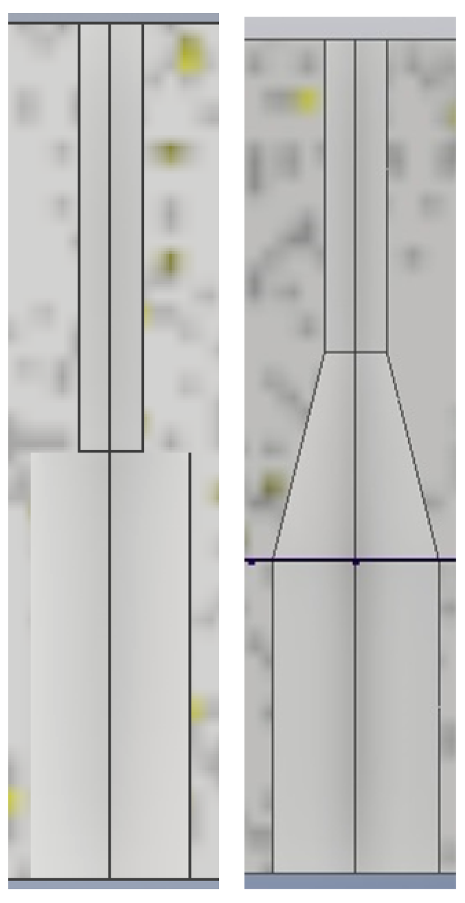
Now, it is possible to compare the initial structure model and the new structure. There is a difference in the approach to modeling in each case (
Figure 1). In the next step, changing the cell dimensions and wall thickness was proposed. The maximum distance between opposite walls was 2 mm and a minimum of 0.5 mm. The wall thickness changes, but all the cells (voids) remain the same.
Here, however, it was necessary to provide a modeling of the vertical transition between cells of different sizes. In most cases, the program did not have problems executing the command. However, for an unknown reason, the model did not generate correctly. It was then necessary to manually change the dimension of more cells.
Subsequent models had two layers, but they did not have smoother transitions between cells. The next modification was the introduction to the models of transitions between layers of different cells. The last modification concerned the scaling of models to adapt them to the requirements of your 3D printer. The final dimensions of the samples were 12 × 12 × 120 mm.
Following the measurements made during the three-point bending test, the maximum linear displacement (deflection) and the maximum reduced and normal stress were determined.
At the first attempt, all test samples had the same dimensions as the previously tested control samples prepared from bone tissue. A sample of 40 mm length, 4 mm height, and 4 mm width was used for a two-layer structure and a half-height sample (2 mm) was used for a single-layer structure. The boundary conditions were adopted as standard for the three-point bending test and the action force was 5 N. The displacement distribution is typical for bending, but the distribution of reduced stresses (Huber–Mises) and normal stresses (from bending) is disturbed in sections where voids occur. It can be seen that the larger the voids, the higher the stress concentration factor.
Changes made to produce the new structure resulted in a reduction in the maximum value of displacement and tension both in the case of the single- and two-layer model. Thus, in the case of the two-layer model, the displacement of 0.011 mm determined for the initial configuration of the voids decreases to 0.0091 mm for the modified configuration. Similarly, it can be seen that the displacement of 0.115 mm decreases to 0.098 mm for the modified configuration of the voids.
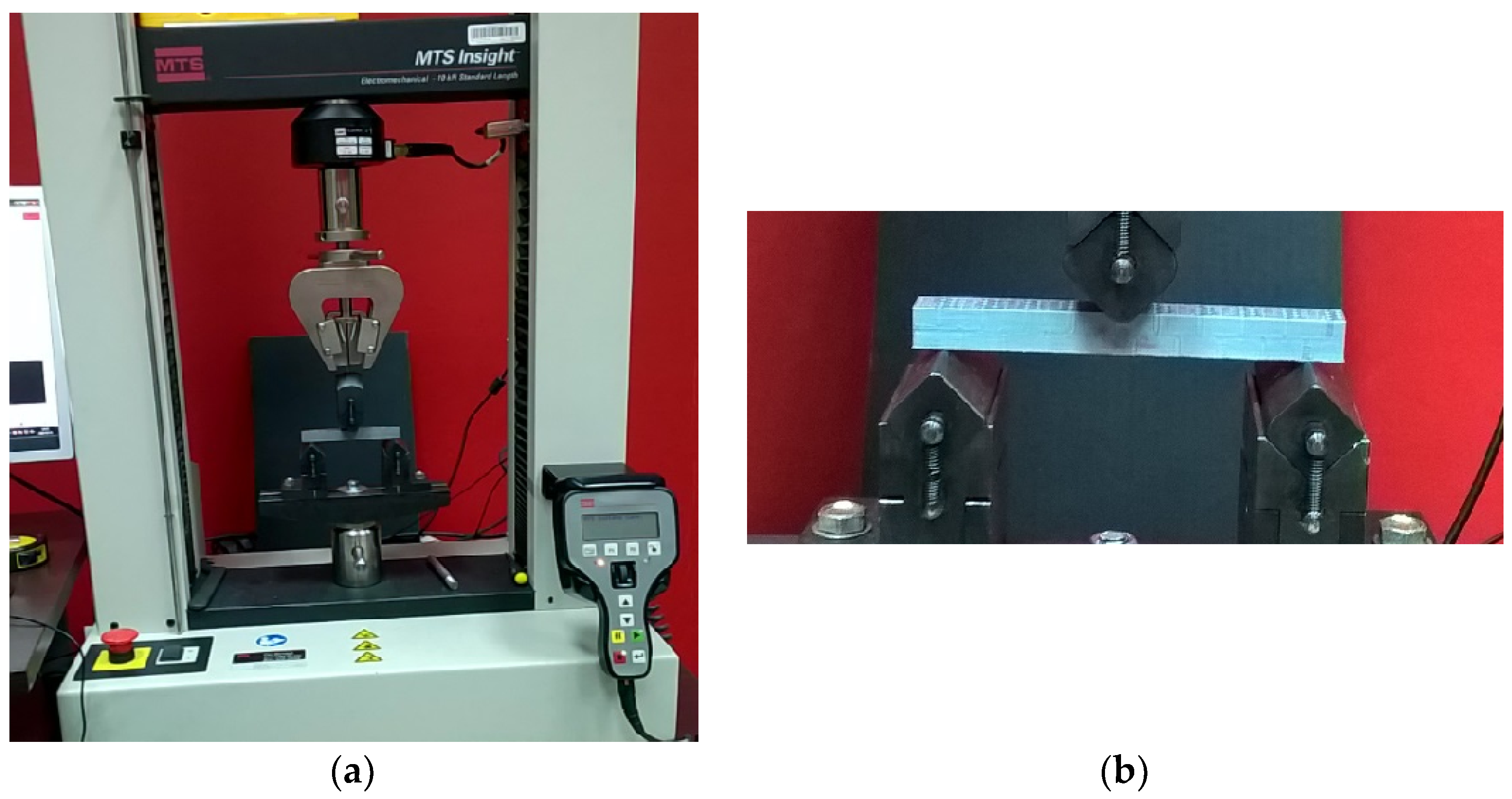
An MTS Insight 10 testing machine was used to perform the strength tests with a detailed presentation of the mounting of the sample. (
Figure 2). A preliminary preparation of the stand was made in order to be able to carry out tests on small dimension samples loaded with reduced forces.
The tests were conducted on samples obtained using the rapid FDM prototyping technique. Based on previous studies, the dimensions of the numerical models were 4 × 4 × 40 mm. Therefore, the dimensions of the smaller and larger cells had to be correspondingly small.
In order to carry out the experiments, samples were made at a scale of 3:1, that is, they were enlarged three times, obtaining a specimen with dimensions of 12 × 12 × 120 mm. With these changes, the available 3D could be used—Prusa i3 MK2. The changes introduced in the numerical model, caused by the notch phenomenon, were also beneficial from a technological point of view. The printer coped with previous samples. As an additional observation, it was not possible to check the quality of the printing in sensitive places (inside the sample).
Considering the capabilities of the printer, it can be said that it coped better with the production of “pass” samples. In the case of a testing machine, performing tests on initial, smaller samples would not cause major problems. Tests on this type of sample have already been performed before.
During the research, six series of tests were performed, with five samples in each test. The difference occurs in the dimensions of the cells, which have different volumes and masses.
3. Results and Discussions
In the following, the results obtained in the research are presented and commented upon.
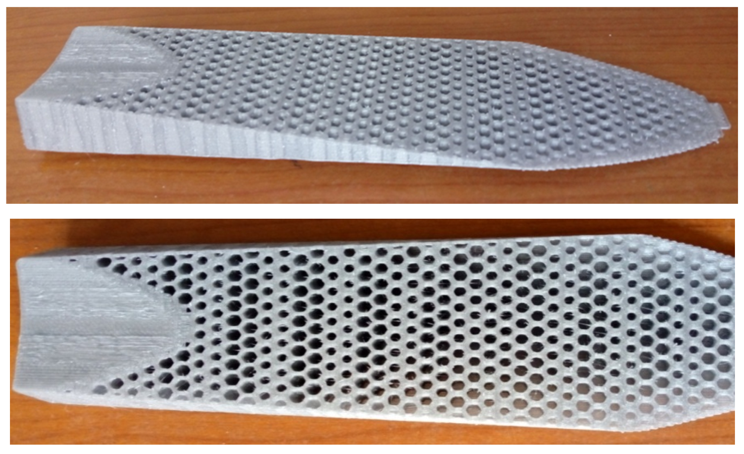
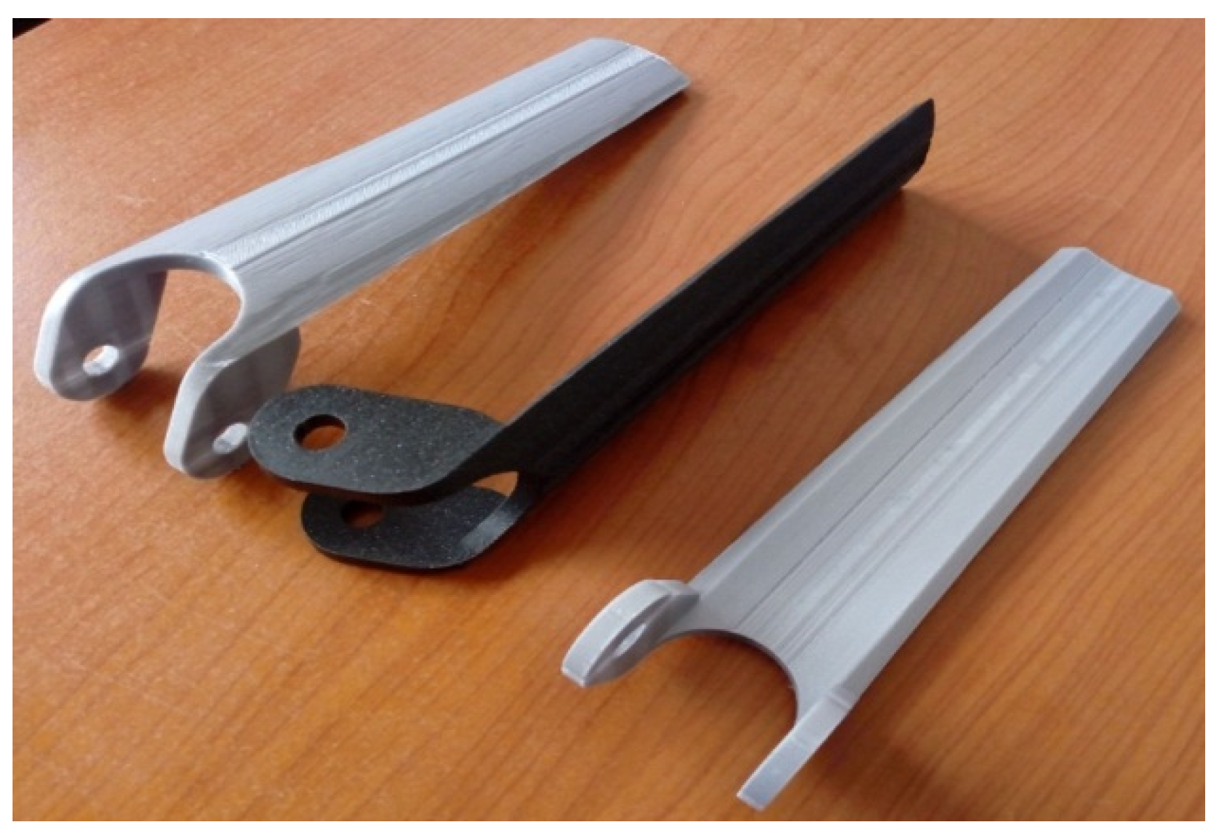
Based on the results obtained from the research, the next step was carried out. This consisted of the development, production, and numerical testing of the child’s upper limb orthosis and the exoskeleton element from the wrist to the elbow. Based on previous research [
24], a reverse honeycomb structure was proposed in a single-layer and double-layer version (
Figure 3 and
Figure 4). In
Figure 4, we can see a diagonal section through both layers of the element. Commercially available ABS (in two colors: gray and black) was used to create this structure. The Prusa i3 MK3S printer was used to create the elements (
Figure 5). For the dimensioning of the elements, the application of the elements to a 12-year-old child (data for the North American population) was considered.
Other requirements were that its structure could be easily made, have the necessary strength and rigidity, and have a simple geometric shape. Several variants with different modifications were tested.
As part of the work, two elements were designed, manufactured, and tested numerically, differing in the way they were combined with other system components.
The single-layer model in two versions and a two-layer model in one version are presented here. The dimensions for each model refer to the basic version. Drawings with dimensions for versions after subsequent modifications are not shown—the extreme dimensions of the models for each version have the same value after each modification. In the case of single-layer models, two versions were proposed, differing in the way they were combined with other elements of the exoskeleton in the area of the elbow joint. The method of connecting elements may vary due to the functions and design of the entire device.
The presented elements contain simplifications and certainly require a refining of the geometry in detail, but for the purposes of this work, i.e., presenting the possibilities of a specific application of the developed structures, it was assumed that they were sufficient. In this case, both the simplicity of the design and execution mattered. An important role was also played by the production time (3D printing), which in the examples presented varied from a dozen to twenty-something hours for one element.
The combination of elements made by means of 3D printing and mass-produced in the construction is herein considered. This would be to reduce the cost of the entire structure while still allowing for customization to the needs of the patient.
Within the study, a new structure was obtained for which a series of geometric parameters was selected that would allow this structure to respond as well as possible to the requirements stated in the design theme. During this time, the realization of this structure can be achieved by rapid prototyping with minimal production costs.
In areas where stress concentration occurs, changes in the geometry should be introduced to minimize any technological notch and, at the same time, maximize the structure (including full filling). Where stresses reach low values, the structure can be thinned to the maximum. Attention should be paid to stiffness—this is the second important factor affecting the proper functioning of the element. If the displacements are too large, the structure should be compacted.
In this respect, after the realization of an initial solution for the structure, numerical simulations were performed that allowed the improvement of the proposed solution for raising the quality of the functionality of the structure.
Boundary conditions, both in the single-layer and double-layer model, were assumed as having contact between the forearm and the element over the entire surface. This is synonymous with the transmission of force between the element and the forearm over the entire inner surface of the element. Impact can occur in one direction or the other. The support was put in place of the pin where all degrees of freedom were removed. The set boundary conditions must ensure that the system is kept in balance; in the case of static calculations, the element cannot behave like a mechanism. In this case, using the action–reaction principle, the given conditions as a moment load at the pin location and the support on the contact surface of the element with the forearm can also be interpreted. One can additionally assume a point load acting tangentially to the external or internal surface of the element along the longitudinal axis or perpendicularly at a selected point of the external surface. Such a load would simulate hitting an obstacle.
In all tests for the double-layer and single-layer model in version 1, the total value of the acting force of 300 N (total load) was assumed. For the single-layer model in version 2, the total value of 100 N acting force was assumed.
The discretization of the models was carried out using tetrahedral elements of the Tet4 type with a linear shape function. The average distance between the nodes was taken as 1 mm. The developed models consist of approximately 400,000 elements and have approximately 120,000 degrees of freedom. Values of forces obtained in experimental tests of structure samples were used as a guide in the selection of the load.
Material parameters provided by the manufacturers for the material, which is ABS, in an unprocessed state were also taken into account. In the case of a double-layer model with a thickness of 12 mm, the set force of 300 N did not cause the yield point to be exceeded in any area; however, for single-layer models with a thickness of 5 mm, zones with stresses exceeding the yield point of the material used appeared. Therefore, in single-layer models for version 2, a force of 100 N was adopted. It should be emphasized that a force of 300 N is in the range of the maximum forces obtained in the experiment for samples with voids. The maximum force had a higher value only for solid samples (no voids).
A slight increase in both reduced and normal stresses can be seen (5–8%). At the same time, the displacement from 1.02 mm decreased to 0.97 mm. It should be noted that the local stress concentration appears in the transition zone from the solid part with the hole for the pin (established restraint) to the zone modified by the structure with voids. It can be seen that the end of the wrist-side element is poorly strained, and even more holes (or larger holes) can be inserted in this zone. The element’s rigidity should be ensured—displacements should not be too large.
It was also noticed that the element geometry influences the obtained stress values. This mainly applies to rounding in transition zones between parts of different widths. Modifications to the element geometry without changing the internal structure are illustrated well in the drawings of stress distribution for a single-layer model with a thickness of 5 mm. In this case, reduced stress decreased from 112 MPa to 78 MPa and normal stress from 88 MPa to less than 75 MPa. Stress concentration still occurs locally in the same area, but the extent of occurrence decreases.
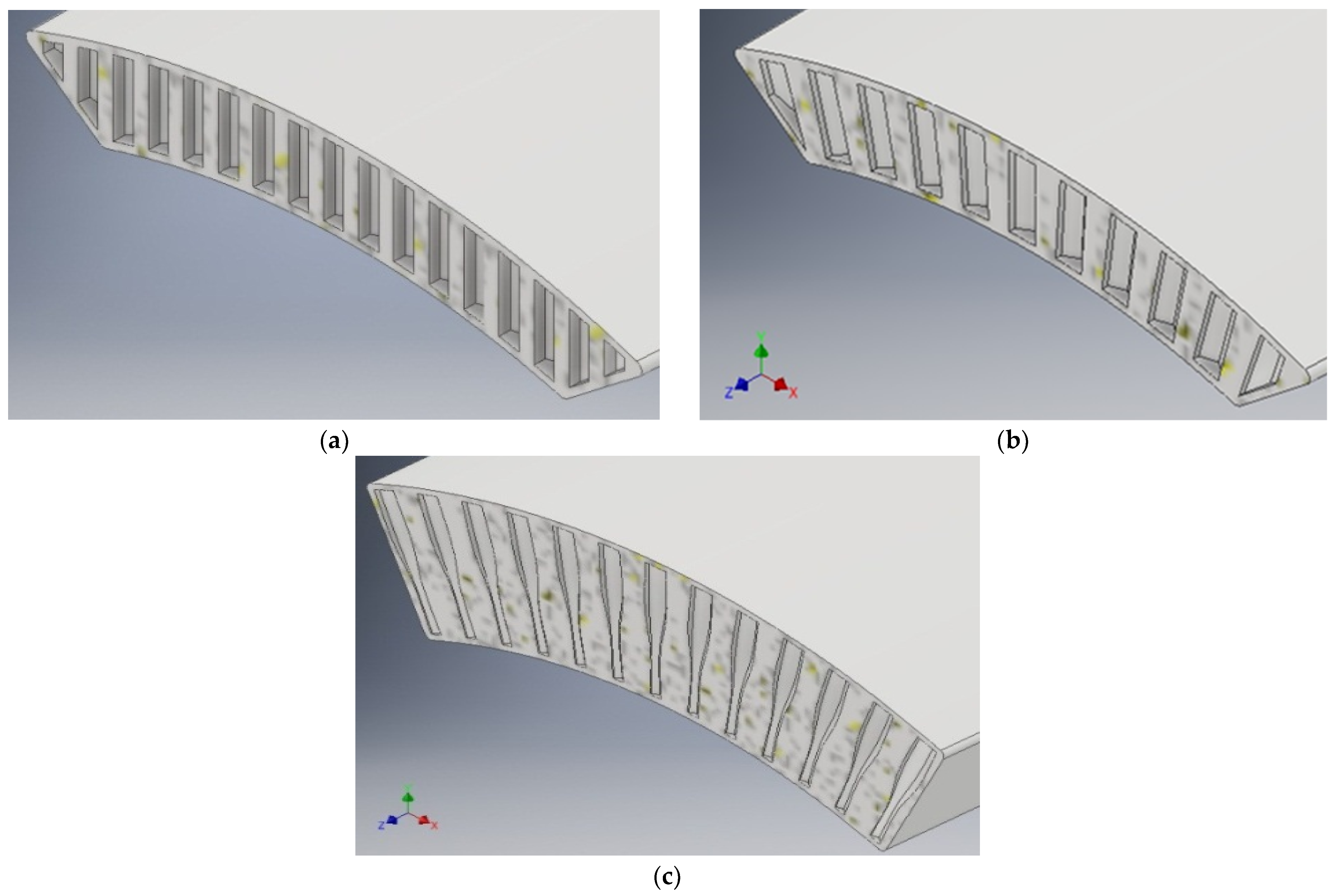
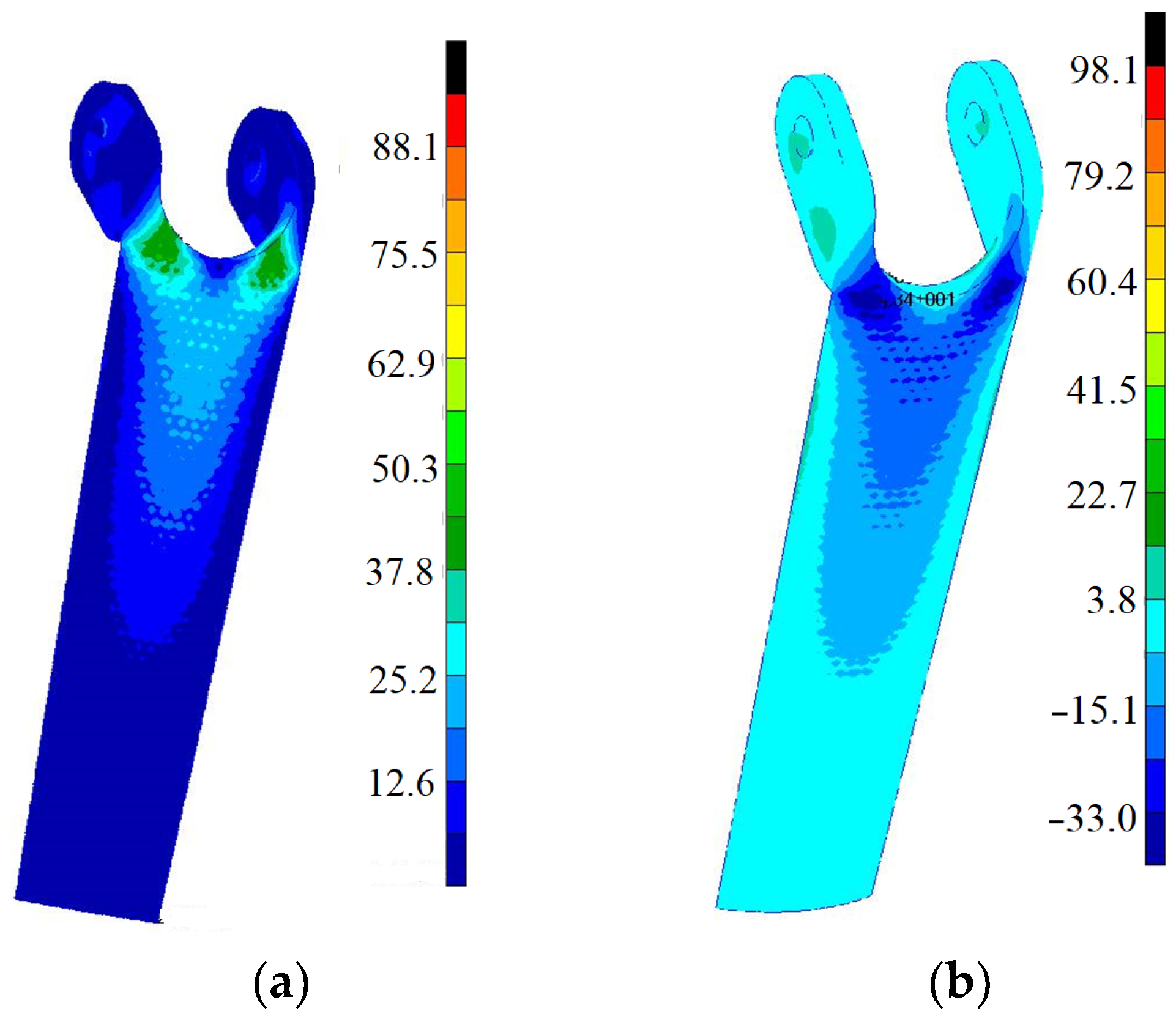
For all single-layer models in version 2, local stress concentration occurs in the transition zone from handles with holes (from the side of the elbow, so-called ears) to the support zone (forearm) from the inside. Certainly, the stress concentration is related to the geometry of the modeled element. Increasing the rounding radius in the transition zone only slightly affected the reduction in maximum stress values. It can be seen that the concentration occurs in a small area from the inside; on the outside of the element, the stresses are much lower (
Figure 6).
The highest values of stress, both reduced and normal, occur in the full model and reach 187 MPa in the case of reduced stresses and 149 MPa in the case of normal stresses. The observed large difference between the values of reduced and normal stresses indicates a significant share of tangential stresses resulting from the nature of the work of the analyzed element for a given static scheme. The stress concentration zone is small compared to the main dimensions of the element (area of several cm2 with reference to approx. 100 cm2 on each side). It is worth noting that the stresses in the remaining area do not exceed 25 MPa in the case of reduced stresses and 23 MPa in the case of normal stresses. On the outer surface, the maximum stress values are much lower. They do not exceed 50 MPa for reduced stresses and 41 MPa for normal stresses.
In the case of a structure with hexagonal holes parallel to each other, maximum stress values are smaller and reach 117 MPa in the case of reduced stresses and 114 Mpa in the case of normal stresses on the inner surface. Similar tendencies occur on the outer surface, where they do not exceed 54 MPa for reduced stresses and −48 MPa for normal stresses.
The lowest values and maximum stresses occur for a structure with holes with axes perpendicular to the outer surface of the element proposed in this work. In this case, the maximum stress values reach 95 MPa in the case of reduced stresses and 98 MPa in the case of normal stresses on the inner surface. On the outer surface, they do not exceed 44 MPa in the case of reduced stresses and −44 MPa in the case of normal stresses. There are still zones with low effort (on the order of several MPa) around the wrist, but the whole element is more evenly stressed. The reduction in element stiffness causes a significant drop in stress in the concentration zone.
Large stress values occur on the surface from the inside of the element and quickly decrease towards the center (in thickness). Considering that the bending strength is about 70 MPa, it can be seen that the element does not have cross-sections in which this value would be exceeded along the entire thickness. Stresses greater than bending strength appear in two areas (symmetrically, in the transition zone from handles with holes to the support zone) in the range of 1/4–1/5 of the thickness.
The comparison shows that the structure with holes with axes perpendicular to the external surface of the proposed element in the stress work offers the best results, and, in terms of displacement, is better than standard structures with voids.
4. Conclusions
Knowing the high potential of new rapid prototyping techniques and the wide applicability of these techniques in different branches of industry, the purpose of the paper can be summarized as follows: The design of a lightweight structure, corresponding to predetermined conditions, achievable by rapid prototyping techniques. The conditions set for the designed element were: to support the given load, to allow the adaptation to a specific external form, to be as easy as possible, to allow modifications according to the requirements, to be executed with owned equipment, and fast machining. The manufacturing technique was also selected in terms of the possibility of the relatively easy personalization of elements by modifying the shape or changing the color of the material.
It is emphasized that the purpose of the research is not the development of a new material but of a new structure, through a design oriented towards fulfilling the previously mentioned purposes and made of known and commercially available materials.
This and previous research on bone tissue has resulted in narrowing the search to structures that mimic biological systems. As a result, the structures with voids were considered.
During the research, it was observed that the properties of the elements can be changed by modifying the distribution of cells and their size. Due to this, it will be possible to adapt the structure to the specific application. The weight of the elements is not the most important criterion for selecting a structure. Changing the dimensions of cells and their distribution alters the properties of all elements with the same weight.
It is also worth noting that the proposed structure allowed for eliminating the problems associated with generating a smooth edge on each side of the manufactured element, and with reference to numerical simulations, it eliminated the problems with modeling the edge in the case of an incomplete number of cells in the series, and thus with setting the boundary conditions on such an irregular edge.
The research carried out in the paper proves that it is possible to obtain new types of structures, useful in biomechanical applications, by using 3D printing but with traditional materials, whose properties are well known. The obtained results indicate great possibilities for using new structures based on traditional materials. These new structures can be extended to other applications in different engineering fields.


