Abstract
The purpose of this paper is to study the axisymmetric vibrations of circular three-layered sandwich plates with a frequency-dependent fractional viscoelastic core and elastic face sheets. First, the equations of motion and related boundary conditions are derived using the Hamilton’s principle for the free vibrations. Then, the governing equations obtained for various boundary conditions are solved and parametric studies are carried out to examine the vibration behavior of circular sandwich plates with a viscoelastic core. The differential transform method (DTM), a well-known semi-analytical–numerical solution technique, is utilized for the eigenvalue analysis. In addition, the finite element (FE) solution obtained with the commercial code ANSYS is added to this comparison. The effect of face and core layer thicknesses and the location of the core layer and core material on the dynamic and damping characteristics of circular sandwich plates with a fractional derivative viscoelastic core is studied in detail.
1. Introduction
Sandwich plates are commonly utilized as structural members in the marine, aerospace and automobile industry due to their tunable vibration damping performance, low specific weight and high stiffness-to-weight ratio. Therefore, a good understanding of the vibration and damping capabilities of such structural members is of decisive importance for the design of optimal structures. In this respect, theoretical and semi-analytical or numerical studies for circular sandwich structures have attracted the attention of many researchers. Sandwich structures, which are widely used in engineering applications, consist of a core material placed between two stiff surface layers. The core of the sandwich plate, which connects the surfaces, allows the entire structure to act as one thick plate while maintaining the integrity of the plate. In addition, sandwich plates show high rigidity and bending resistance despite their low weight. Therefore, there are many studies on the dynamic analysis of sandwich panels, and only a brief summary of the literature will be presented. In their pioneering work, Midlin et al. [1] studied the vibrations of a circular disk with free edges. Then, Pardoen [2] investigated the asymmetric free vibration characteristics of circular and annular plates using the finite element method (FEM). In this study, the Fourier series approach was used to model the geometric asymmetry of the circular and annular plates. Gu et al. [3] conducted the free vibration analysis of annular plates with both uniform and non-uniform thickness using the differential quadrature method (DQM). Some difficulties were found when applying discontinuities to geometry and loads; however, they found that the solutions were more applicable than the quadrature element method and found good agreement with the literature. Hashemi et al. [4] carried out the vibration analysis of circular plates using classical plate theory and FSDT in comparison with the three-dimensional Ritz solution. Mode shape switching was examined in graphical form for the Winkler foundation stiffness parameters. Lee et al. [5] used a semi-analytical solution to calculate the natural frequencies and mode shapes for circular plates with holes using the Fourier series method, and compared the results with the finite element results. The effect of the eccentricity of a hole on natural frequency was also investigated, and high accuracy and rate of convergence were obtained in this paper. Ciancio et al. [6] studied the buckling of circular, annular plates of continuously variable thickness used as internal bulkheads in submersibles. Ha et al. [7] performed an experimental study and numerical analysis for the free vibration of flat plates under dry and wet conditions. Kim et al. [8] investigated the behavioral characteristics of the lateral deflection of a simply supported perforated steel plate subjected to axial compression. Wu et al. [9] studied the free vibration of circular plates using GDQM. They investigated the effects of ring supports, stepped thickness and elastic restraints. Wu et al. [10] performed free vibration analysis of circular plates with variable thickness and elastic restraints using DQM. Peng et al. [11] used the differential quadrature method to solve nonlinear vibration equations of circular plates. The method was validated with the analytical results, and good accuracy and convergence were obtained. Yalcin et al. [12] investigated the vibration characteristics of circular thin plates for different boundary conditions using the differential transform method (DTM). This method is a semi-numerical and analytical approach to solve different types of differential equations. In this study, the calculated dimensionless frequency values were compared using the Bessel solution, and the results showed good agreement. Ozakca et al. [13] conducted the buckling analysis of circular and annular plates using the finite element method. Zur and Jankowski [14] studied the free vibration of FGM porous circular plates; the influences of the even and uneven distributions of porosity, power-law index, diverse boundary conditions and the neglected effect of the coupling in-plane and transverse displacements on the dimensionless frequencies of the circular plate were presented in their paper.
However, studies on the vibration and damping behavior of circular sandwich plates are very limited due to the additional difficulties arising from regularity and boundary conditions. Yu and Koplik [15] presented the torsional vibrations of circular sandwich plates. Kao and Ross [16] investigated the natural frequencies of circular sandwich panels with clamped and simply supported boundary conditions. Mirza and Singh [17] presented the axisymmetric vibration of three-layered circular sandwich plates. The two face layers were assumed to be isotropic and the thick core layer was an aluminum honeycomb. Alipour and Shariyat [18] examined the free vibration analysis of circular/annular composite sandwich plates with auxetic cores. Zhou and Stronge [19] presented axisymmetric and non-axisymmetric modes of circular sandwich panels. The finite element method was applied to validate the analytical modeling. Lal and Rani [20] studied the axisymmetric vibrations of circular sandwich plates with a shear deformable variable thickness stiff core. Karamooz et al. [21] derived frequency equations for the in-plane vibration of the orthotropic circular annular plate for general boundary conditions. Magnucki et al. [22] conducted a theoretical and experimental study of a bending circular sandwich plate. Ganesan and Roy [23] carried out the vibration analysis of circular plates with a viscoelastic damping layer. Nguyen-Xuan et al. [24] proposed an effective approach for a fifth-order shear deformation theory for composite sandwich plates. Pai and Palazotto [25] conducted the impact analysis of a sandwich plate with an elastic foundation at a low velocity. Magnucki et al. [26] investigated the buckling analysis of symmetrical circular sandwich plates with a radially variable foam core. In this study, the mechanical properties of the core varied along the radial direction, remaining constant in the face sheets. The mathematical model of the displacements consisted of the shear effects. The accuracy of the analytical model was validated using finite element analysis. Liu et al. [27] examined the three-dimensional vibrations of circular and annular plates under different combinations of boundary conditions. Mao et al. [28] examined the load-carrying capacity of simply and clamp-supported circular sandwich plates with a metal foam core. Jalali and Heshmati [29] examined the buckling behavior of circular sandwich plates with tapered cores and carbon nanotube faces.
As previously reported in the literature, DTM has the advantage of obtaining more accurate results with less computational cost. This technique is based on the Taylor series expansion, first proposed by Zhou [30] in 1986.
This study presents the vibration analysis of circular sandwich plates with a frequency dependent viscoelastic core and isotropic face layers using DTM. The Hamilton’s principle is used to obtain the governing equations as well as the boundary conditions. The results are compared with those already presented in the open literature for circular sandwich plates for various boundary conditions, and a good correlation is observed. Then, the effects of system parameters such as core and face layer thicknesses, core material and location of the core layer on the dynamic behavior of the circular sandwich plates are studied.
2. Materials and Methods
The governing equations of motion, together with the boundary conditions for the vibration of the circular sandwich plates, are derived by Hamilton’s principle:
- -
- The damping core is assumed to be linearly viscoelastic and the material properties are frequency- and temperature-dependent.
- -
- The layers are considered incompressible and transverse displacement remains constant throughout the plate’s thickness. The layers are perfectly bonded and there is no slip between the layers.
- -
- Linear vibration analysis is conducted because of the small deformations and strains.
The geometry and dimensions of the circular sandwich plate and the displacement of each layer are given in Figure 1 and Figure 2.
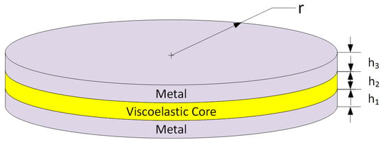
Figure 1.
Geometry and layout of the circular sandwich plate.
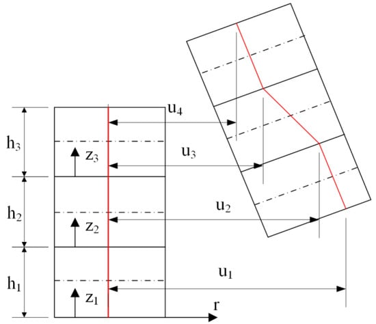
Figure 2.
Displacement components of the face sheets and core.
In the light of the relevant assumptions, the kinematic relationships are obtained for the geometry depicted in Figure 2.
where is the thickness, is axial and is the transverse displacement field, is the axial displacement at and is the axial displacement at for the kth layer. In cylindrical coordinates, the strain displacement relations can be given as follows:
The stress–strain relation for the isotropic faces are:
where is the Young’s modulus and is the Poisson ratio of the kth layer. If the material is frequency- and temperature-dependent viscoelastic, it converts to , where is the complex modulus of the viscoelastic core with the frequency in Hertz. Hamilton’s principle is used to derive the governing equations for the vibration analysis of the circular sandwich plate:
where δL is the Lagrangian, δK is the kinetic energy and δU is the strain energy for the upper and lower elastic face layers and the circular sandwich plate with a viscoelastic core, which can be written as follows:
where ρ(k) is the density of each layer. Note that the problem is modelled as axisymmetric and the shear strains of the face sheets and the normal strains of the core are added in the energy expressions, and all inertia terms are considered in the governing equations.
The governing equations in terms of cross-section force and moments are derived from Equations (2)–(5) and (8) for the free vibration of the circular sandwich plate:
In addition, the boundary conditions are derived as:
where
The open forms of the equations of motion and derived boundary conditions are presented in the Appendix A.
The regularity conditions at r = 0 for the symmetrical vibrations of the circular sandwich plate are as follows:
.
3. Differential Transform Method (DTM)
The Taylor series expansion-based differential transform method (DTM) is the one of the semi-analytical–numerical techniques, and by using this technique, it is possible to obtain highly accurate results for differential or integro-differential equations. The kth order differential transform of a function w = w(r) is defined about a point r = r0 in domain R and the differential transform of the kth derivative of the function w(r) in one variable is defined as follows [12,31]:
where w(r) is the original and Wk is the transformed function. On the other hand, the inverse transformation of the original function w(r) is given as follows [12,31]:
Combining Equations (21) and (22), one may be given [12,31]:
Equation (23) indicates that Taylor’s expansion is the source of the idea of the differential transform method. However, the differential transform method does not estimate the derivatives symbolically. An iterative procedure can be used to evaluate the relative derivatives defined by the transformed equations of the original functions. The function w(r) is expressed by a finite series, and Equation (22) can be given:
Depending on the convergence of the eigenvalues, it is possible to limit the series size. In this study, the value of N represents the number of terms in Taylor’s series, and Equation (24) implies that is negligibly small. Table 1 shows some useful theorems that are needed in the differential transform method.

Table 1.
DTM theorems [12,32].
In addition, from Theorems 3–5 presented in Table 1, one can derive the following:
This rule will be very important in the transformation of governing differential equations since there are many terms of dependent functions and their derivatives multiplied with r and r2.
The differential transforms of Equations (A1)–(A5) are also presented in Appendix A in (A6)–(A10), using the rules in Table 2 and the rule presented in Equation (25).

Table 2.
DTM theorems for various edge boundary conditions (r = R).
4. Validation
Before starting the parametric study, it is necessary to conduct a validation. For this purpose, dynamic analyses of circular sandwich plates are conducted and compared with the results that already exist in the literature. Additionally, FEM analyses are performed using the commercial code ANSYS and added into the comparison to validate the proposed model and the solution methodology.
The first problem investigated in this paper is the vibration analysis of a circular sandwich plate with isotropic face sheets and a soft core. The solutions are conducted for free and simply supported boundary conditions. The second example is the vibration and damping analysis of a circular sandwich plate with aluminum face layers and a frequency independent viscoelastic core.
4.1. Example 1
The first problem is the vibration analysis of a circular sandwich plate with isotropic face sheets and a soft core for various BCs, i.e., simply supported and free boundary. The geometric and mechanical properties of the examined circular sandwich plate are as presented in Table 3. The free and simply supported boundary conditions at the plate edge are applied as given in Table 2.

Table 3.
Material properties and dimensions [19].
For the first example, solutions are achieved for the boundary conditions with free and simply supported edges using N = 50 terms in DTM calculations. The first four mode shapes are presented in Figure 3 and Figure 4. Both Table 4 and Table 5 demonstrate good agreement between the results conducted by DTM, FEM results obtained with ANSYS and the existing results in the literature for free edge and simply supported edge sandwich plates.
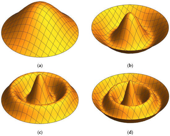
Figure 3.
First four symmetrical mode shapes for the free edge condition: (a) mode 1, (b) mode 2, (c) mode 3, (d) mode 4.
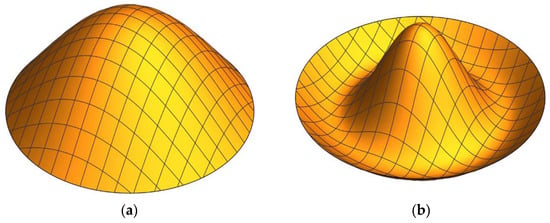
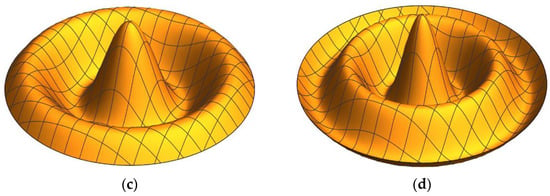
Figure 4.
First four symmetrical mode shapes for the simply supported edge condition: (a) mode 1, (b) mode 2, (c) mode 3, (d) mode 4.

Table 4.
Natural frequencies of a free edge sandwich plate with a radius of 78 mm.

Table 5.
Natural frequencies of a simply supported sandwich plate with a radius of 78 mm.
4.2. Example 2
The second example considered in this paper is the dynamic analysis of a circular sandwich plate with aluminum face layers and a frequency independent viscoelastic core. The geometric and material parameters of the selected problem are given in Table 6. The frequencies and modal loss factors are determined by Equation (26).
where ωn defines the complex natural frequency.

Table 6.
Material properties and dimensions [33].
Table 7, Table 8 and Table 9 show the natural frequencies and modal loss factors of the circular sandwich plate for free, clamped and simply supported boundary conditions for the first six modes, respectively. In this example, the DTM and finite element (FE) results obtained with ANSYS Classical 2019 R2 are compared. A total of 2000 solid eight-node axisymmetric quadrilateral finite elements are used in the FE model.

Table 7.
The natural frequencies of circular sandwich plate for free boundary condition.

Table 8.
The natural frequencies of circular sandwich plate for clamped boundary condition.

Table 9.
The natural frequencies of circular sandwich plate for simple support boundary condition.
The finite element results by the commercial software ANSYS were also added into this comparison. However, defining the complex modulus of the viscoelastic core layer was not possible using this software; therefore, the undamped ANSYS solution was used to obtain the modal loss factors using the modal strain energy method (MSE) as given in [34].
where ηn is the nth modal loss factor and ηc is the material loss factor of the viscoelastic core, Vc,n is the elastic strain energy of the core and VT,n is the total strain energy at the nth modal frequency of the circular sandwich plate.
The results for the frequencies show that the DTM and ANSYS solutions are quite close to each other and a good agreement is achieved. There is a similar correlation for modal loss factors between the results of the undamped ANSYS solution combined with the MSE approach and the DTM solution results. In addition, considering the results from Table 7, Table 8, Table 9, Table 10, Table 11 and Table 12, it is decided that it would be appropriate to use N = 60 terms in the remaining part of this study.

Table 10.
Modal loss factors (%) of circular sandwich plate for free boundary condition.

Table 11.
Modal loss factors (%) of circular sandwich plate for clamped boundary condition.

Table 12.
Modal loss factors (%) of circular sandwich plate for simple support boundary condition.
5. Parametric Analyses
A series of parametric calculations are performed to understand the effect of system parameters on the dynamic behavior of the circular sandwich plates. The geometrical parameters and the choice of core material on the damping and the dynamic characteristics of a clamped circular sandwich plate with a viscoelastic core layer are analyzed in this section. The bottom and top face sheets are an isotopically elastic aluminum material with , , the radius of the plate is constant and R = 500 mm.
The core layer material is selected as viscoelastic, hence, its mechanical properties such as dynamic modulus and loss factor are highly dependent on frequency and temperature. A ten-parameter fractional derivative material model is selected to model the frequency-dependent damping layer’s behavior [35,36]:
where is the frequency, is the relaxation time, is the static shear modulus, and are the fractional time derivatives and and are the fitting parameters. Table 10 lists the unknown material properties for damping polymers in the fractional derivative model.
Equation (28) is used to compute the viscoelastic core’s loss factor and shear modulus using data from Table 13. First, the effect of the thickness of the core layer on vibration and damping behavior is examined. The results depicted in Figure 3 are achieved keeping constant both the face layers’ thicknesses h1 = h2 = 2.5 mm, and the thickness of the core layer varies from 0.2 to 30 mm. The results show that the core layer thickness and polymeric core material choice have a significant effect on the modal loss factors and natural frequencies.

Table 13.
Viscoelastic material properties at T0 = 20 °C [35].
Two of the damping polymers, DYAD 606 and polyurethane, are stiff compared to the remaining three, namely, 3M Y966, EAR C-1002 and polyisoprene. As the core layer thickness increases for soft materials, it experiences large shear deformations, and the radial bending rigidity of the cross-section decreases. As a result, the fundamental natural frequency decreases with h2, as can be observed from Figure 5a. However, using stiff material as a core layer, the bending rigidity increases and a continuous increase can be observed for the frequency with h2.
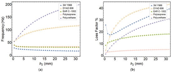
Figure 5.
Variation of the frequency and loss factor with h2 (h1 = 2.5 mm, h3 = 2.5 mm, R = 500 mm): (a) natural frequency, (b) modal loss factor.
On the other hand, there are two mechanisms that affect the structural damping of the sandwich plate. The first one is the core layer material loss factor that is a function of frequency and temperature. The second one is the ratio of the stored strain energy of the core layer to the total strain energy. The core layer is forced in shear due to the relative motion of the face layers in bending. As the core layer thickness increases, this ratio also increases, as expected.
However, this mechanism loses its efficiency when the core thickness becomes too large compared to the face layers, and the modal loss factor converges to the material loss factor. In general, the modal loss factors increase with h2 due to the increase in damping material mass, as expected. One exception is the 3M Y966 material at small values of h2. The reason seems to be that the material loss factor shows significant variation at around 30 Hz, which is the fundamental frequency of the sandwich plate. As the core thickness increases, the natural frequency decreases, as well as the material loss factor. This can be seen in Figure 5a,b in detail.
Then, the effect of face layer thickness on the vibration and damping characteristics of the symmetrically sectioned circular sandwich plate is investigated by keeping the core layer constant (h2 = 5 mm) and changing h1 and h3. The fundamental natural frequency and the modal loss factor are depicted in Figure 6. As the face sheet thickness increases, the natural frequency increases, as expected, due to the increasing bending rigidity. The natural frequency exhibits the highest values for the stiff polyurethane core and the lowest values for the soft 3M Y966 core.
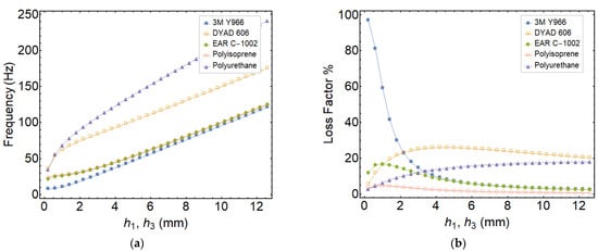
Figure 6.
Variation of the frequency and loss factor with h1 and h3 (h2 = 5 mm, R = 500 mm): (a) natural frequency, (b) modal loss factor.
For thin face layers, the core layer cannot be deformed in shear efficiently. On the other hand, when the face layer thicknesses increase, the stored strain energy in the core layer increases as well. Therefore, the modal loss factor increases with face layer thickness for small values of h1 and h3 for all of the core materials except 3M Y966, as can be seen in Figure 6b. Then, the modal loss factor starts to decrease for the higher values of face layer thickness. This is mainly due to the decreasing ratio of stored modal strain energy by the core layer to the total strain energy.
Lastly, the effect of the location of the core layer on the vibration and damping characteristics of the unsymmetrically sectioned circular sandwich plate is investigated by keeping the core layer and total thickness constant (h2 = 5 mm and h1 + h2 + h3 = 12.5 mm) and changing h1 for examining the effects of geometric asymmetry.
As can be seen in Figure 7, the frequency is maximum for the asymmetric sections for soft core materials, as highlighted in the existing studies on sandwich structures available in the literature [31,32]. On the other hand, this effect seems contrary to the loss factor where the maximum values are for symmetrical sections. This is an expected outcome, since the core experiences the greatest magnitudes of shear stress for symmetrical sections, as indicated by Arikoglu et al. [31].
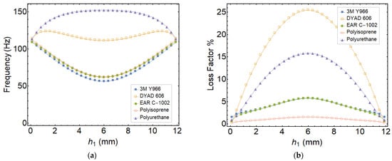
Figure 7.
Variation of the frequency and loss factor with location of core layer (h2 = 5 mm, total thickness is constant and h1 + h2 + h3 = 12.5 mm, R = 500 mm): (a) natural frequency, (b) modal loss factor.
6. Discussion
This study presents the vibration and damping analysis of three-layered circular sandwich plates with a frequency-dependent viscoelastic core layer using the differential transform method. First, the governing equations, boundary conditions and related differential transforms were obtained. Then, inverse transformation was performed and the frequencies and loss factors obtained for various end conditions. The results were validated against those that exist in the open literature and the commercial FEM software ANSYS, and a very good correlation was observed. This study shows that DTM can be utilized for the vibration and damping analysis of circular sandwich plates as an efficient, fast converging tool, which, to the best of the author’s knowledge, has been achieved for the first time. Finally, parametric analyses were carried out to understand the effects of geometric and material parameters on the dynamic response of circular sandwich plates. The followings are observed:
- -
- The modal loss factors and natural frequencies are highly influenced by the core layer thickness and polymeric material properties.
- -
- As the core layer thickness increases for soft materials, it experiences large shear deformations, and the radial bending rigidity of the cross-section decreases. On the other hand, the bending rigidity continuously increases with the frequency when the core layer is stiff.
- -
- As the face thicknesses increase, the natural frequency increases, as expected, due to the increased bending stiffness. For thin face layers, the core layer cannot be deformed in shear efficiently. On the other hand, when the face layer thicknesses increase, the stored strain energy in the core layer increases as well.
- -
- The core layer experiences the greatest magnitudes of shear stress for symmetrical sections.
The study conducted here can be extended to the asymmetrical vibration analysis of circular laminated composite and sandwich plates for future work.
Funding
This research received no external funding.
Institutional Review Board Statement
Ethical review and approval were waived for this study as it does not involve humans or animals.
Informed Consent Statement
Not applicable.
Data Availability Statement
The data used to support the findings of this study are included within the article.
Conflicts of Interest
The author declares no conflict of interest.
Appendix A
The open forms of Equations (9)–(13) are as follows:
The transformed equations are obtained as follows:
Equations (A6) to (A10) are recurrence relations starting from k = 0. They will give an algebraic equation system from which the unknown DTM coefficients are solved in terms of given and missing initial conditions at r = 0 (w(0), u1′(0),…, un+1′(0)). Then, the transformed boundary conditions given in Table 2 are used to solve the vibration frequencies and mode shapes. As an example, for the clamped end conditions of the three-layered sandwich plate, the end conditions in Table 2 give:
where U1(k), U2(k), U3(k), U4(k) and W(k) depend on U1(1), U2(1), U3(1), U4(1) and W(0), and this equation can be represented in matrix form:
the frequencies of vibration are solved from:
and the eigenvectors are obtained by setting for the related mode :
References
- Mindlin, R.D.; Deresiewicz, H. Thickness-Shear and Flexural Vibrations of a Circular Disk. J. Appl. Phys. 1954, 25, 1329–1332. [Google Scholar] [CrossRef]
- Pardoen, G.C. Asymmetric Vibration and Stability of Circular Plates. Comput. Struct. 1978, 9, 89–95. [Google Scholar] [CrossRef]
- Gu, H.Z.; Wang, X.W. On the free vibration analysis of circular plates with stepped thickness over a concentric region by the differential quadrature element method. J. Sound Vib. 1997, 202, 452–459. [Google Scholar] [CrossRef]
- Hosseini-Hashemi, S.; Omidi, M.; Taher, H.R.D. The validity range of CPT and Mindlin plate theory in comparison with 3-D vibrational analysis of circular plates on the elastic foundation. Eur. J. Mech. -A/Solids 2009, 28, 289–304. [Google Scholar] [CrossRef]
- Lee, W.-M.; Chen, J.T.; Lee, Y.T. Free vibration analysis of circular plates with multiple circular holes using indirect BIEMs. J. Sound Vib. 2007, 304, 811–830. [Google Scholar] [CrossRef]
- Ciancio, P.M.; Reyes, J.A. Buckling of circular, annular plates of continuously variable thickness used as internal bulkheads in submersibles. Ocean Eng. 2003, 30, 1323–1333. [Google Scholar] [CrossRef]
- Ha, Y.-J.; Park, B.-J.; Kim, Y.-H.; Lee, K.-S. Experimental Investigation on Structural Responses of a Partially Submerged 2D Flat Plate with Hammering and Breaking Waves for Numerical Validation. J. Mar. Sci. Eng. 2021, 9, 621. [Google Scholar] [CrossRef]
- Kim, J.-H.; Park, D.-H.; Kim, S.-K.; Kim, J.-D.; Lee, J.-M. Lateral Deflection Behavior of Perforated Steel Plates: Experimental and Numerical Approaches. J. Mar. Sci. Eng. 2021, 9, 498. [Google Scholar] [CrossRef]
- Wu, T.Y.; Liu, G.R. Free vibration analysis of circular plates with variable thickness by the generalized differential quadrature rule. Int. J. Solids Struct. 2001, 38, 7967–7980. [Google Scholar] [CrossRef]
- Wu, T.Y.; Wang, Y.Y.; Liu, G.R. Free vibration analysis of circular plates using generalized differential quadrature rule. Comput. Methods Appl. Mech. Eng. 2002, 191, 5365–5380. [Google Scholar] [CrossRef]
- Peng, J.-S.; Yuan, Y.-Q.; Yang, J.; Kitipornchai, S. A semi-analytic approach for the nonlinear dynamic response of circular plates. Appl. Math. Model. 2009, 33, 4303–4313. [Google Scholar] [CrossRef][Green Version]
- Yalcin, H.S.; Arikoglu, A.; Ozkol, I. Free vibration analysis of circular plates by differential transformation method. Appl. Math. Comput. 2009, 212, 377–386. [Google Scholar] [CrossRef]
- Ozakca, M.; Taysi, N.; Kolcu, F. Buckling analysis and shape optimization of elastic variable thickness circular and annular plates-I. Finite element formulation. Eng. Struct. 2003, 25, 181–192. [Google Scholar] [CrossRef]
- Żur, K.K.; Jankowski, P. Multiparametric Analytical Solution for the Eigenvalue Problem of FGM Porous Circular Plates. Symmetry 2019, 11, 429. [Google Scholar] [CrossRef]
- Yu, Y.-Y.; Koplik, B. Torsional Vibrations of Homogeneous and Sandwich Spherical Caps and Circular Plates. J. Appl. Mech. 1967, 34, 787–789. [Google Scholar] [CrossRef]
- Kao, J.-S.; Ross, R.J. Fundamental natural frequencies of circular sandwich plates. AIAA J. 1969, 7, 2353–2355. [Google Scholar] [CrossRef]
- Mirza, S.; Singh, A.V. Axisymmetric Vibration of Circular Sandwich Plates. AIAA J. 1974, 12, 1418–1420. [Google Scholar] [CrossRef]
- Alipour, M.M.; Shariyat, M. Analytical layerwise free vibration analysis of circular/annular composite sandwich plates with auxetic cores. Int. J. Mech. Mater. Des. 2017, 13, 125–157. [Google Scholar] [CrossRef]
- Zhou, D.W.; Stronge, W.J. Modal frequencies of circular sandwich panels. J. Sandw. Struct. Mater. 2006, 8, 343–357. [Google Scholar] [CrossRef]
- Lal, R.; Rani, R. On radially symmetric vibrations of circular sandwich plates of non-uniform thickness. Int. J. Mech. Sci. 2015, 99, 29–39. [Google Scholar] [CrossRef]
- Karamooz, M.R.; Forouzan, M.R. Frequency equations for the in-plane vibration of orthotropic circular annular plate. Arch. Appl. Mech. 2011, 81, 1307–1322. [Google Scholar] [CrossRef]
- Magnucki, K.; Jasion, P.; Magnucka-Blandzi, E.; Wasilewicz, P. Theoretical and experimental study of a sandwich circular plate under pure bending. Thin-Walled Struct. 2014, 79, 1–7. [Google Scholar] [CrossRef]
- Roy, P.K.; Ganesan, N. A Vibration and Damping Analysis of Circular Plates with Constrained Damping Layer Treatment. Comput. Struct. 1993, 49, 269–274. [Google Scholar] [CrossRef]
- Nguyen-Xuan, H.; Thai, C.H.; Nguyen-Thoi, T. Isogeometric finite element analysis of composite sandwich plates using a higher order shear deformation theory. Compos. Part B Eng. 2013, 55, 558–574. [Google Scholar] [CrossRef]
- Pai, P.F.; Palazotto, A.N. A higher-order sandwich plate theory accounting for 3-D stresses. Int. J. Solids Struct. 2001, 38, 5045–5062. [Google Scholar] [CrossRef]
- Magnucka-Blandzi, E.; Wisniewska-Mleczko, K.; Smyczynski, M.J. Buckling of symmetrical circular sandwich plates with variable mechanical properties of the core in the radial direction. Compos. Struct. 2018, 204, 88–94. [Google Scholar] [CrossRef]
- Liu, C.-F.; Lee, Y.-T. Finite element analysis of three-dimensional vibrations of thick circular and annular plates. J. Sound Vib. 2000, 233, 63–80. [Google Scholar] [CrossRef]
- Mao, R.W.; Lu, G.X.; Wang, Z.H.; Zhao, L.M. Large deflection behavior of circular sandwich plates with metal foam-core. Eur. J. Mech. -A/Solids 2016, 55, 57–66. [Google Scholar] [CrossRef]
- Jalali, S.K.; Heshmati, M. Buckling analysis of circular sandwich plates with tapered cores and functionally graded carbon nanotubes-reinforced composite face sheets. Thin-Walled Struct. 2016, 100, 14–24. [Google Scholar] [CrossRef]
- Zhou, J.K. Differential Transformation and Its Application for Electrical Circuits; Huazhong University Press: Wuhan, China, 1986. [Google Scholar]
- Arikoglu, A.; Ozkol, I. Vibration Analysis of Composite Sandwich Plates by the Generalized Differential Quadrature Method. AIAA J. 2012, 50, 620–630. [Google Scholar] [CrossRef]
- Arikoglu, A.; Ozkol, I. Vibration analysis of composite sandwich beams with viscoelastic core by using differential transform method. Compos. Struct. 2010, 92, 3031–3039. [Google Scholar] [CrossRef]
- Demir, O.; Balkan, D.; Peker, R.C.; Metin, M.; Arikoglu, A. Vibration analysis of curved composite sandwich beams with viscoelastic core by using differential quadrature method. J. Sandw. Struct. Mater. 2020, 22, 743–770. [Google Scholar] [CrossRef]
- Ungar, E.E.; Kerwin, E.M. Loss Factors of Viscoelastic Systems in Terms of Energy Concepts. J. Acoust. Soc. Am. 1962, 34, 954–957. [Google Scholar] [CrossRef]
- Arikoglu, A. A new fractional derivative model for linearly viscoelastic materials and parameter identification via genetic algorithms. Rheol. Acta 2014, 53, 219–233. [Google Scholar] [CrossRef]
- Arikoglu, A. Multi-objective optimal design of hybrid viscoelastic/composite sandwich beams by using the generalized differential quadrature method and the non-dominated sorting genetic algorithm II. Struct. Multidiscip. Optim. 2017, 56, 885–901. [Google Scholar] [CrossRef]
Publisher’s Note: MDPI stays neutral with regard to jurisdictional claims in published maps and institutional affiliations. |
© 2022 by the author. Licensee MDPI, Basel, Switzerland. This article is an open access article distributed under the terms and conditions of the Creative Commons Attribution (CC BY) license (https://creativecommons.org/licenses/by/4.0/).