Abstract
The purpose of this paper is to show some routes in describing the mechanism responsible for the formation of the temperature difference at the boundaries of the microfluidic hybrid aligned nematic (HAN) channel, initially equal to zero, if one sets up the stationary hydrodynamic flow or under the effect of an externally applied shear stress (SS) to the bounding surfaces. Calculations based on the nonlinear extension of the classical Ericksen–Leslie theory, supplemented by thermomechanical correction of the SS and Rayleigh dissipation function while accounting for the entropy balance equation, show that the is proportional to the heat flux across the HAN channel and grows by up to several degrees under the influence of the externally applied SS. The role of with a sharp triangular profile across the HAN in the production of the highest is also investigated.
PACS:
61.30.-v; 47.57.Lj; 65.40.De
1. Introduction
Consisting of anisotropic molecules, liquid crystal (LC) materials were called curious soft matter until their impressive impact on modern technology. The primary technological revolution was brought by these LC materials in the field of displays. With the development of the LC display market, the question arises about the following areas of application of LC materials. Perhaps there is no more suitable direction for the application of LC materials than LC sensors (LCSs) and LC actuators (LCAs) [1]. They have various advantages in comparison with other types of microsensors and microactuators; simple structure, high shape adaptability, easy downsizing, and low driving voltages. This is because LC materials are extremely sensitive to external disturbances and can be used for the construction of stimuli-responsive devices, such as LCSs or LCAs [1]. Nematic liquid crystal (NLC) channels or capillaries of appropriate size are microdevices in which the molecular orientations can be manipulated by forces applied macroscopically or can be generated locally within the microfluidic nematic channel [2] or capillary [3]. A challenging problem in all such systems is the precise handling of nematic microvolume, which in turn requires self-contained micropumps with small package sizes exhibiting either a very small displacement volume (displacement pumps) or a continuous volume flow (dynamic pumps). One of the pumping principle in the microsized LC channel confined between two infinitely long boundaries is based on the coupling between the tangential component of the shear stress (SS) and the director field , which describes the preferred orientation of the molecules, together with accounting the effect of the temperature gradient [4,5].
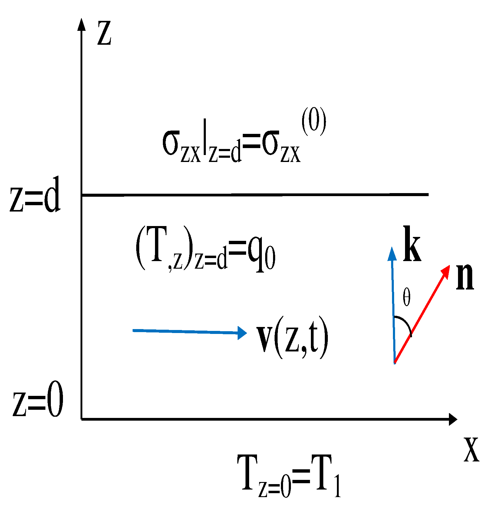
It has been shown that, due to the temperature gradient , the horizontal hybrid aligned nematic (HAN) microfluidic channel, being initially at rest, starts moving in the horizontal direction if heated from below or above [6,7,8]. In the case when the director is anchored homeotropically to the cooler (), lower boundaries and homogeneously to the hotter () upper boundaries, due to coupling between and , the hydrodynamic flow [7] in the horizontal direction is excited. Here, is the temperature difference on the HAN boundaries, d is the thickness of the HAN channel, and is the unit vector taken parallel to the horizontal boundaries of the HAN channel (see Figure 1).
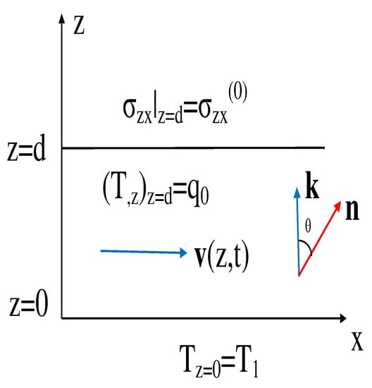
Figure 1.
The geometry used for theoretical analysis.
The magnitude of the flow is proportional to [6,7,8], where is the tangential component of the thermomechanical stress tensor , is the viscosity, and is the thermomechanical constant [6]. The direction of the hydrodynamic flow is influenced by the character of the preferred anchoring of the average molecular direction to the boundaries of the HAN channel and the heat flux across the bounding surface [7,8]. Measurements of the temperature of the induced flow were performed on the HAN cell [9], and the main result of that experimental study is the estimation of the thermomechanical constant 10 J/K m [9].
Despite the fact that the possibility of formation of hydrodynamic flows in nematic channels under the influence of temperature gradients has been theoretically described since [6,7,8], only detailed numerical simulations performed within the framework of the extended Ericksen-Leslie theory [10,11] allowed us to recreate the complete picture of the formation of flows in nematic microchannels and capillaries. One of the aims of this paper is to describe the various regimes of hydrodynamic flow formation due to the interaction between the temperature and director field gradients obtained by numerical modeling of these processes. This paper is devoted to the possibilities of computational methods implemented in the framework of the nonlinear extension of the Ericksen–Leslie theory while accounting for the entropy balance equation [12]. Another purpose of our paper is to show some routes in describing the mechanism responsible for formation of the temperature difference on the boundaries of the HAN channel, being initially equal to zero, if one sets up the stationary hydrodynamic flow or under the effect of the externally applied shear stress to the bounding surfaces.
It should be noted that a whole class of confined active fluids under external shear stress [13,14,15] as well as the problem of thermomechanical coupling in cholesterics [16] are not included in the scope of our research interests. And this is despite the fact that research in active matter has been fostered by many unexpected finding, ranging from spontaneous flow to symmetry breaking in exotic active emulsions.
This is the first review to describe the role of thermomechanical force in the formation of hydrodynamic flow in microsized nematic channels and capillaries in detail. It is based on the nonlinear extension of the Ericksen–Leslie theory, supplemented by thermomechanical correction of the shear stress and the Rayleigh dissipation function, and takes into account the entropy balance equation. The fact that the main results were obtained by numerical methods indicates that the experimenters still have a lot of work to do in order to create a more complete picture of formation of hydrodynamic flows in microsized nematic channels and capillaries.
The layout of this section is as follows. The following section presents the system of hydrodynamic equations describing both the reorientation of the director field and the flow of liquid crystal in a microfluidic HAN channel containing the temperature gradient under the action of the external shear stress. The numerical results for the number of hydrodynamic regimes, caused by both the shear stress and the heat flux across the bounding surfaces of the HAN channel, describing the orientational relaxation of the director, velocity, and temperature are given in Section 2. The role of flow in temperature gradient formation across a hybrid aligned nematic channel is given in Section 3. The conclusions are summarized in in Section 4.
2. Shear-Driven Flow Regimes in Microfluidic Nematic Devices: Tumbling and Laminar
In the case of the stationary shear stress flow , the director is oriented in the shear plane, where the plane is defined by the liquid crystal flow (the direction x coincides with the unit vector ) and the velocity gradient in the z direction coincides with the unit vector ; y is the vorticity axis coinciding with the unit vector (see Figure 1). It has long been thought that, in shear flows, the dynamics of nematics always produces an alignment regime, where the director aligns at a stationary angle [17,18,19],
with respect to the direction of the flow velocity , when the hydrodynamic torque,
exerted per unit LC volume in a shear flow vanishes. Here, , and are the rotational viscosity coefficients (RVCs), and are the Leslie coefficients, and is the shear rate. However, it has been found that some LC materials exhibit an unusual type of instability, when the director continuously rotates in the shear flow. It is clear from Equation (1) that, if or (because, in practice, ), then no real solution for exists. Physically, this means that, in this case, the director tumbles under the shear flow of the nematic.
An interesting aspect of the tumbling rotation of the director’s field in the shearing flow should be noted here [20]. In this case, there is a certain value of the shear rate, above which the director rotates out from the plane, and there is a steady-state solution without tumbling.
Among the many questions that arise in this connection, we are interested in two.
First, how does the viscous torque affect the character of the director field (or the polar angle ) evolution to its stationary orientation with respect to the nematic flow in the microsized HAN channel when the director is strongly anchored to both boundaries under the influence of the tangential component of the shear stress while accounting for the temperature gradient ? This is investigated for two types of nematic phases: first, for the “laminar” case of nematic phase, when , and, second, for the “tumbling” case of nematic phase, when [17,18,19]. For instance, the liquid crystal composed of molecules belongs to the laminar nematic phase, whereas the liquid crystal composed of molecules [21] belongs to the tumbling nematic phase. Second, is it possible to set up a temperature difference across the HAN microfluidic channel, initially being equal to zero, under the action of the tangential component of the shear stress applied to the boundary of the LC channel?
The answers to these questions are given within the framework of the nonlinear extension of the classical Ericksen–Leslie theory [10,11], supplemented by thermomechanical correction of the shear stress and Rayleigh dissipation function while taking into account the entropy balance equation [12]. It has recently been shown, both experimentally [22] and numerically [23], that only stationary flow with a triangular sharp profile and position of the maximum in the vicinity of the restricted boundaries may achieve the highest temperature difference in the HAN microfluidic channel of few degrees. By means of other hydrodynamic flow with profiles, which cannot demonstrate the sharp growth of across the HAN channel, one can achieve the same result only by using of the “high-speed” hydrodynamic flow ∼0.1 μm/s [22]. However, taking into account that some LC systems driven by external SS exhibit such non-equilibrium phenomena as a tumbling behavior [7,8,23], the mechanical description can shed some light on the problem of temperature gradient formation; when under certain conditions, the thermomechanical force can overcome elastic, viscous, and anchor forces and cause a temperature gradient across the HAN channel.
2.1. Formulation of the Relevant Equations for Dynamical Reorientation in Microsized Nematic Fluids
First, we consider the description of the physical mechanism responsible for the shear-driven nematic flow in microfluidic hybrid aligned nematic (HAN) channels under the action of the external shear stress applied to the upper boundary of this channel (see Figure 1):
We consider a hybrid aligned channel composed of both the laminar and tumbling types nematics, which is bounded by two horizontal surfaces at a distance of d on a scale of the order of tens of micrometers. According to this geometry, the director is maintained in the -plane (or in the -plane), defined by the heat flux normal to the horizontal boundaries of the LC channel. As we deal with the HAN channel under the influence of both the SS and the heat flux perpendicular to the HAN channel, taking into account the fact that the length of the channel L is much greater than the thickness d, it can be assumed that the component of the director as well as the rest of the physical quantities depend only on the z- coordinate and time t. Here, denotes the angle between the director and the unit vector (see Figure 1). In order to understand how the viscous , elastic and thermomechanical torques as well as the tangential component of the shear stress affect the character of the director field evolution to its stationary orientation with respect to the nematic flow , we must formulate the boundary conditions for the temperature , velocity , and the director fields.
We consider a hydrodynamic regime where the HAN channel is subjected to uniform heating from above, for instance by the laser irradiation [24], while director is strongly anchored to both solid surfaces, homeotropically to the lower cooler (), and homogeneously to the upper bounding surfaces, where
whereas the boundary conditions for the temperature field are
Here, is the heat conductivity coefficient perpendicular to the director whereas is the heat flux across the upper boundary. As a result, we obtaina picture where there is a balance between the heat flux ; SS ; and the viscous, elastic, and anchoring forces, and in general, the LC fluid settles down to a stationary flow in the horizontal direction [7,8]. Under the assumption of an incompressible fluid, the hydrodynamic equations describing the orientation dynamics induced by both SS and can be derived from the torque, linear momentum, and the entropy balance equations for such a LC system.
Taking into account the micro-size of the HAN channel, we can assume that the mass density is constant across the LC film, and thus, we deal with an incompressible liquid. The incompressibility implies that there is only one nonzero component of the vector , .
If the director is disturbed by both the shear stress and the heat flux generated by the uniform heating from above, the relaxation of to its stationary orientation in the HAN channel is governed by elastic , viscous , and thermomechanical torques exerted per unit LC’s volume. Here, is the viscous, is the thermomechanical, and is the thermal contributions to the full Rayleigh dissipation function [7,8]. The set of functions , , and are the hydrodynamic functions, , , , and , whereas are six Leslie coefficients, and and are the heat conductivity coefficients parallel and perpendicular to the director , respectively. In turn, denotes the elastic energy density, and are the splay and bend elastic constants, and is the material derivative of the director .
The hydrodynamic equations describing the reorientation dynamics in our case, when there is the heat flux through the upper boundary of the HAN microfluidic channel and under the action of SS , can be obtained from the torque balance equation [7,8] , which has the form
whereas the Navier–Stokes equation can be written as [7,8]
where is the mass density of the nematic phase; is the full ST; and , , and are the ST components corresponding to the elastic, viscous, and thermomechanical forces, respectively, while is the hydrostatic pressure in the HAN microsized channel and is the unit tensor.
When the temperature gradient is set across the HAN channel, we expect that the temperature field satisfies the entropy balance equation [7,8,12]
where is the heat flux and is the heat capacity of the liquid crystal phase.
To describe the evolution of the director field (or the polar angle ) to its stationary orientation and exciting the velocity field caused by both the heat flux and the external SS , we consider the dimensionless analog of the torque and linear momentum balance equations as well as the entropy balance equation.
The dimensionless torque balance equation describing the reorientation of the director field (or the polar angle ) to its stationary orientation can be written as [7,8]
where , is the derivative of with respect to , is the dimensionless temperature, is the nematic-isotropic (NI) transition temperature, , , , and are the splay and bend elastic constants of the nematic phase, is the dimensionless time, denotes the dimensionless distance away from the lower solid surface, is the dimensionless velocity, is the dimensionless RVC, is the parameter of the nematic system, and is the thermomechanical constant [9]. Notice that the overbars in the space variable z and velocity u have been eliminated and that and are the highest values of the RVC and the splay constant in the temperature interval belonging to the nematic phase. In the case of an incompressible fluid. The dimensionless Navier–Stokes equation reduces to [7,8]
where and ; is the full dimensionless Rayleigh dissipation function; and is the dimensionless hydrostatic pressure in the HAN channel, whereas is an extra one parameter of the nematic system. The ST component is given by [7] .
When the temperature gradient is set across the HAN channel, we expect that the temperature field satisfies the dimensionless entropy balance equation: [7,8]
where , and and are two extra parameters of the nematic system. Note that the overbars in the z space variable and in the last four Equations (9)–(12) have also been eliminated.
In order to elucidate the role of both the heat flux and the external SS on the reorientation process in the microsized HAN channel, we consider the hydrodynamic regime when the director is strongly anchored to both solid surfaces, homeotropically to the lower, cooler boundary (), whereas on the upper boundary, it is assumed that the heat flux is vanished or restricted. In this case, the boundary conditions must satisfy the following equations
where is the dimensionless heat flux across the upper boundary of the HAN channel.
The velocity on the lower boundary must satisfy the no-slip boundary condition,
whereas on the upper boundary the SS is applied as
Now, the reorientation of the director in the microsized HAN channel confined between two solid surfaces, when the relaxation mode is governed by viscous, elastic, thermomechanical forces and the SS with accounting for the heat flux , can be obtained by solving the system of nonlinear partial differential Equations (9), (10), and (12), with the appropriate boundary conditions for the polar angle , temperature (Equation (13)), and the velocity (Equations (14) and (15)) as well as with the initial condition
2.2. Numerical Results for the Relaxation Modes in the HAN Channel
First, we focus on the problem of how much the viscous torque influences the evolution of the director field (or the polar angle ) to its stationary distribution across the microfluidic HAN channel with the temperature gradient. In our case, the is set by the heat flux (see Equation (13)) directed across the microfluidic HAN channel.
Calculations of the temperature dependence as well as a comparison of the RVCs values and , both for and , at temperatures corresponding to the nematic phase, are given in Table 1.

Table 1.
The RVC values and and their ratio for 5CB and 8CB nematic liquid crystals. The values of the phase transition temperatures NI are K and ∼313 K, for 5CB and 8CB, respectively. All data for the RVCs are given in [21].
The rest material parameters of these 5CB and 8CB nematic crystals are the mass density ∼10 kg/m3 and the experimental data for elastic constants [25] and varying between 6 and 13 pN, and 7 and 14 pN, respectively. Therefore, the highest values are pN, pN, Pa s, and Pa s, respectively. Next, we use the measured values obtained by adiabatic screening calorimetry and photopyroelectric methods for the specific heat J/kg K [26], the thermal conductivity coefficients and W/m K [27], the calculated value of the thermomechanical constant J/m K [9], and measured values of the Leslie coefficients () [21].
The set of parameter values involved in Equations (9), (10), and (12) is , , , and . Using the fact that , the Navier–Stokes Equation (10) can be considerably simplified as velocity adiabatically follows the motion of the director. Thus, the whole left-hand side of Equation (10) can be neglected, reducing it to
while Equation (12) can also be significantly simplified. Since both parameters and , and the entire left part of Equation (12) and the second term can be neglected, so the Equation (12) takes the form:
The last equation has a solution
From a physical point of view, this means that the temperature field across the HAN cell under the above conditions is proportional to the heat flux across the upper bounded surface when the temperature on the lower surface is kept constant.
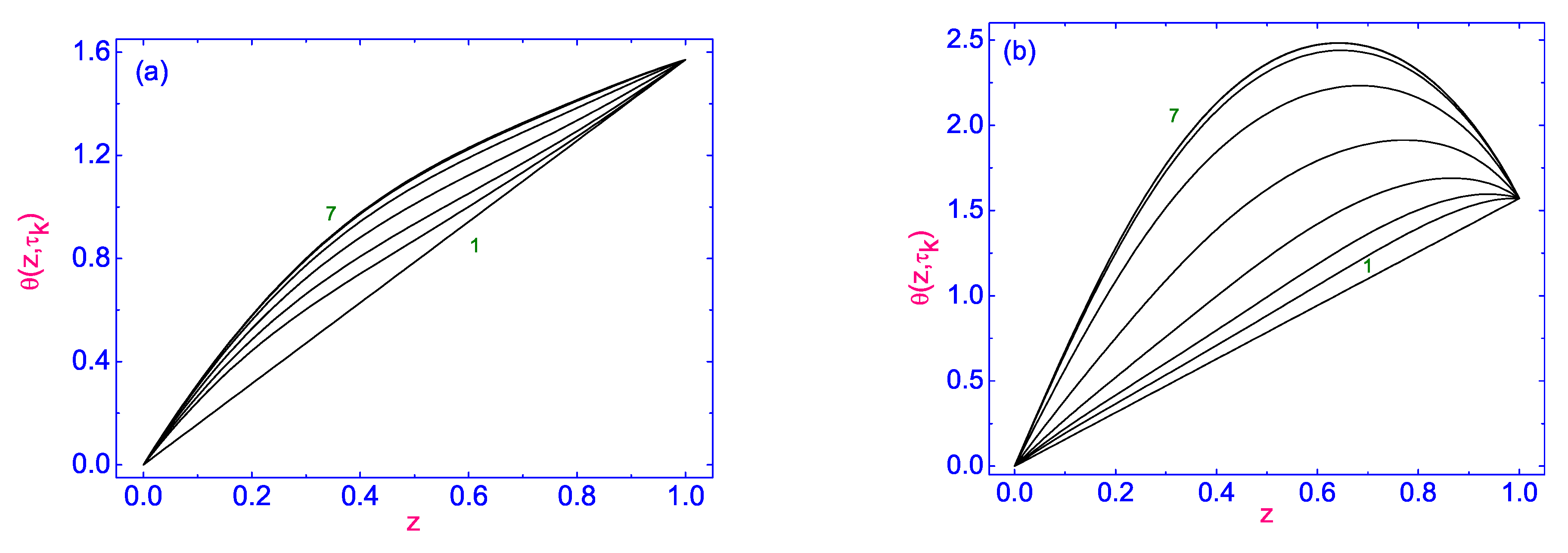
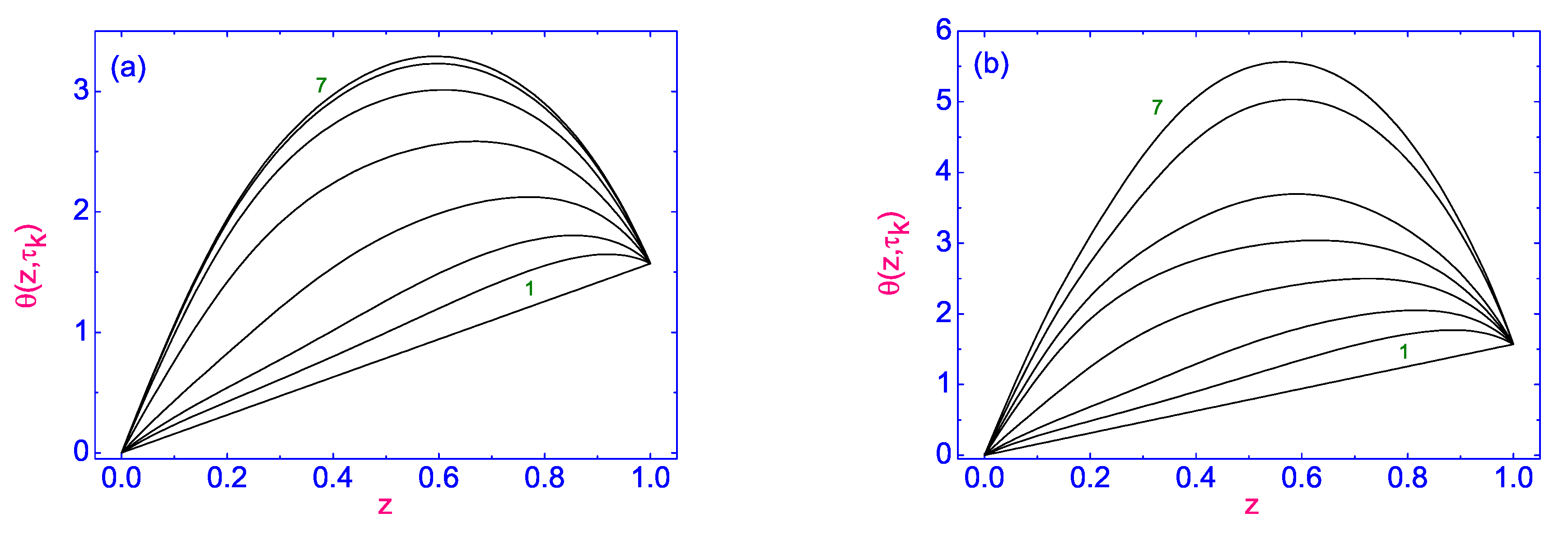
In the case when the SS is equal to 10 (∼5 Pa) and there is the heat flux 200 nW/ directed to the bulk of the nematic channel, the evolution of the director field to its stationary orientation in the microsized HAN channel, which is described by the polar angle for different times starting from (curve 1) to (∼0.07 s) (curve 7) for both cases 5CB (see Figure 2a) and 8CB (Figure 2b), is shown in Figure 2.
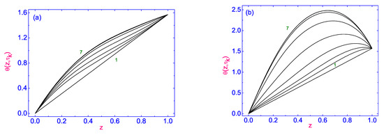
Figure 2.
(a) The evolution of the polar angle to its stationary distribution across the HAN microfluidic channel under the effect of SS 5 Pa) for different times starting from (curve 1) to 0.07 s) (curve 7). Here, . (b) The same as in (a) but for the evolution of to its stationary distribution across the HAN microfluidic channel. Here, is equal to .
All calculations in this paper were carried out by the numerical relaxation method [28], whereas the relaxation criterion was chosen to be equal to and, then, the numerical procedure was carried out until a prescribed accuracy was achieved. Here is the iteration number.
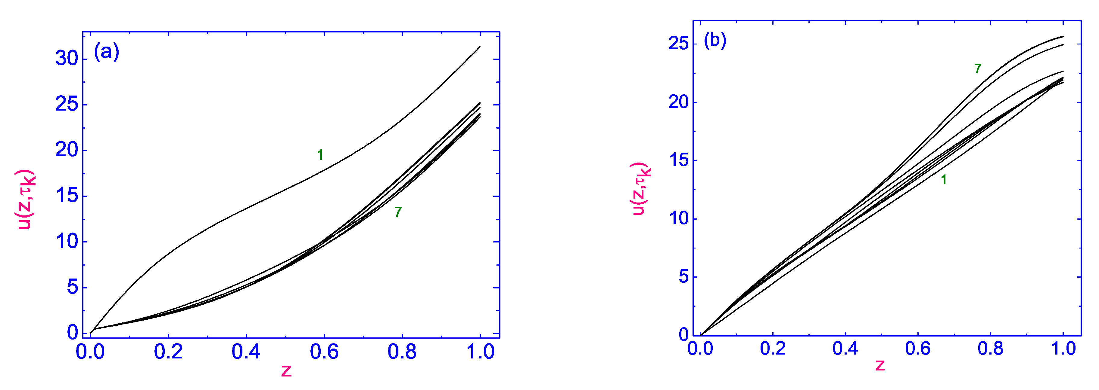
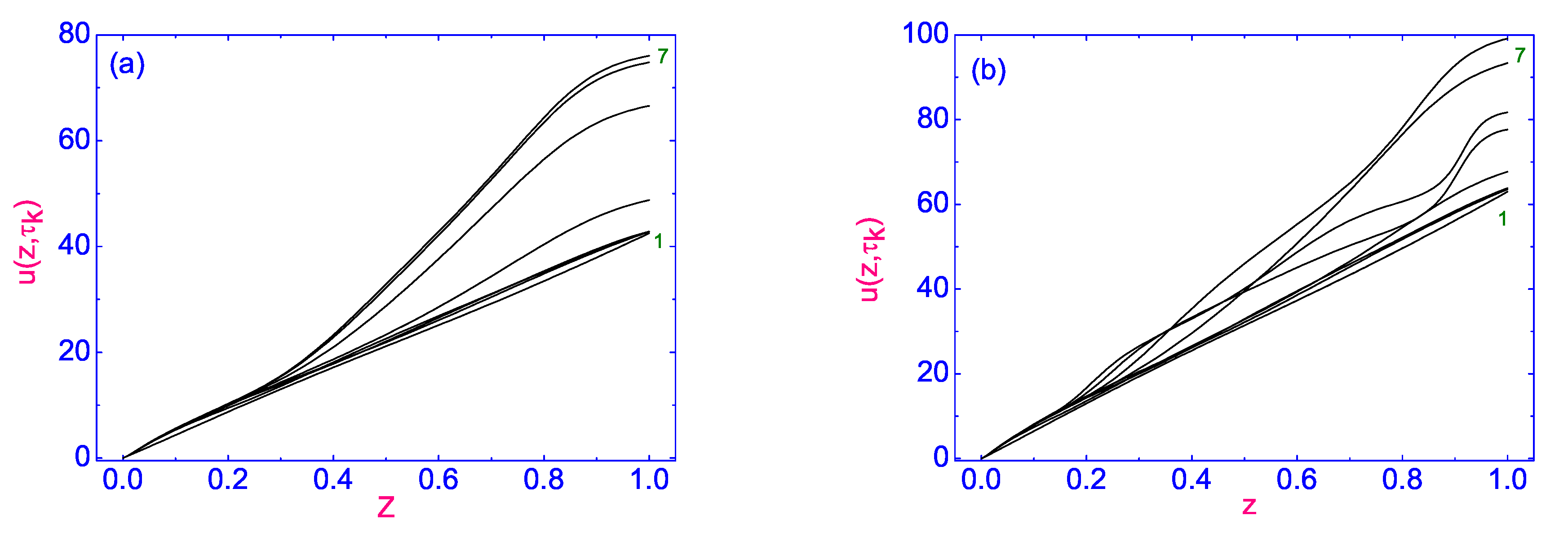
In turn, the relaxation of the velocity field to its stationary distribution across the HAN microfluidic channel under the effect of the same SS (∼5 Pa) for different times starting from (curve 1) to (∼0.07 s) (curve 7) both for (see Figure 3a) and (see Figure 3b) nematics, is shown in Figure 3.
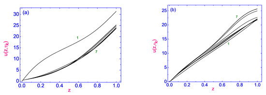
Figure 3.
(a) The relaxation of the velocity field to its stationary distribution across the HAN microfluidic channel under the effect of SS 5 Pa) for different times starting from (curve 1) to 0.07 s) (curve 7). Here, . (b) The same as in (a) but for the relaxation of the velocity field to its stationary distribution through the HAN microfluidic channel. Here, is equal to .
First, the effect of the viscous torque , or , on the evolution of the velocity field is manifested in the qualitative difference in the velocity profiles for and nematics. In the case of , we have concave profiles (see Figure 3a), while in the case of , these profiles represent almost linear dependencies at the final stage of evolution, where the velocity increases from zero () at the lower boundary of the channel to the value (∼0.7 mm/s) at the upper boundary. In the case of , the value of velocity at the upper boundary is equal to (∼0.73 mm/s). Second, the main effect of the viscous torque , or , is manifested in the character of evolution of the director field to its stationary orientation in the microsized HAN channel, which is described by the polar angle . Indeed, in the case of , the polar angle increases monotonically from 0 to ∼, whereas in the case of , the polar angle increases monotonically from 0 to in the vicinity of the centrum of the HAN channel, with a subsequent decrease to the value of ∼ at the upper boundary of the HAN channel. Thus, the main effect of is to influence the nature of the reorientation of the director field to its stationary orientation in the microsized HAN channel, which is described by the polar angle . In the case of the tumbling type nematic phase, composed of molecules, when , the director tumbles under shear flow of the nematic, whereas in the case of the laminar type nematic phase, composed of molecules, when , the dynamics of nematic liquid crystals produces the alignment regime.
In turn, when the SS is increased and equal to (∼10 Pa) (see Figure 4a) and (∼15 Pa) (see Figure 4b) and there is a heat flux at nW/ in the case of the tumbling type nematic phase composed of molecules, when , the evolution of the directors field to its stationary orientation in the vicinity of the centrum of the HAN channel undergoes a qualitative change.
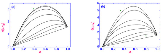
Figure 4.
(a) The evolution of the polar angle to its stationary distribution across the HAN microfluidic channel in the case of the tumbling type nematic phase composed of molecules and under the effect of SS (∼10 Pa) for different times starting from (curve 1) to (∼0.07 s) (curve 7). Here, . (b) The same as in (a) but with (∼15 Pa) and (∼0.1 s). Here, , and is equal to .
According to our calculations, the shear stress produces the velocity field directed in the positive direction (see Figure 5) and its effect on the director distribution across the HAN microfluidic channel is so strong that, in the middle part of the nematic channel, the biggest value of the polar angle is equal to at (∼15 Pa) and the director practically executes a full cycle of rotation (see Figure 4b). That influence decreases with a further decrease in . However, taking into account that the director field is strongly anchored to both boundaries of the HAN channel, homeotropically to the lower and homogeneously to the upper, the balance of the viscous, elastic, thermomechanical, and anchoring forces and the SS applied to the upper restricted surface leads to rotation of the director field mainly in the middle part of the HAN microfluidic channel.

Figure 5.
(a) The relaxation of the velocity field to its stationary distribution across the HAN microfluidic channel in the case of the tumbling type nematic phase composed of molecules and under the effect of SS (∼10 Pa) for different times starting from (curve 1) to (∼0.07 s) (curve 7). Here, . (b) The same as in (a) but with SS and (∼0.1 s). Here, , and is equal to .
The maximum absolute value of the dimensionless velocity in the microsized HAN channel at the final stage of the relaxation process is equal to ∼75 (2.266 mm/s) at (∼10 Pa) (see Figure 5a) and is ∼95 (2.871 mm/s) at (∼15 Pa) (see Figure 5b).
In the case when the heat flux nW/ across the upper boundary is directed to the bulk of the tumbling type nematic phase composed of molecules whereas the SS is applied to the upper restricted surface, the relaxation of the temperature field to its stationary distribution across the HAN channel is characterized by an almost linear dependence from the temperature at the lower boundary (∼307 K) to the temperature at the upper boundary (see Figure 6).

Figure 6.
Plot of relaxation of the dimensionless temperature at the upper boundary of the tumbling type nematic phase to its stationary value for three values of SS: (curve 1), 20 (curve 2), and 30 (curve 3). The curves correspond to the heat flux nW/, directed across the upper boundary.
Calculations show that, under the effect of the lower SS (see Figure 6 (curve 1)) and higher (see Figure 6 (curve 3)), the heating of the upper boundary is characterized practically by the same value of : (∼311.5 K) and (∼311.3 K) but not for (∼310.6 K). Note that, in all of these cases, the dimensionless temperature at the lower boundary is kept constant (∼307 K) and the vertical temperature gradient is created across the HAN microfluidic channel, directed towards the warmer upper boundary. Thus, the highest temperature difference (∼4.5 K), which was initially equal to 0, is built up in the HAN microfluidic channel under the effect of the lower SS and after time (∼0.07 s).
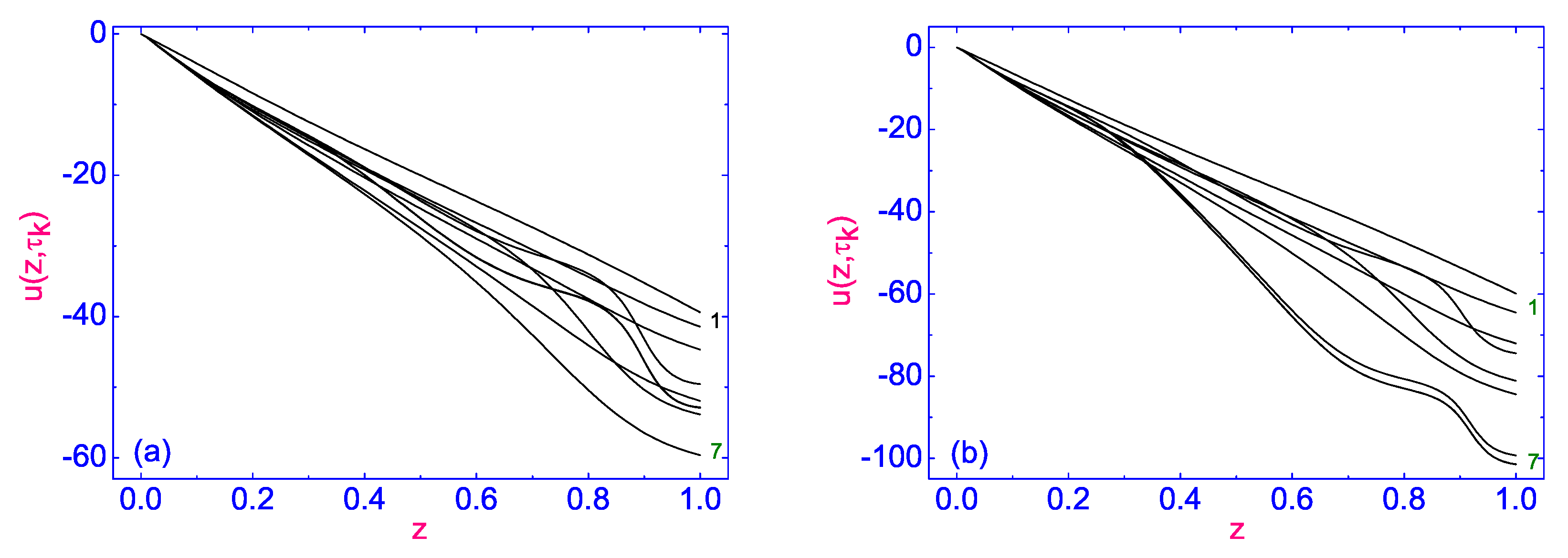
The effects of SS directed in the negative direction both on the evolution of director field to its stationary orientation in the microsized HAN channel composed of molecules, which is described by the polar angle (see Figure 7) and the velocity field (see Figure 8) for different times starting from (curve 1) to (∼0.07 s) (curve 7), are shown in Figure 7 and Figure 8, respectively.

Figure 7.
(a) The evolution of the polar angle to its stationary distribution across the HAN microfluidic channel composed of molecules and under the effect of SS (∼10 Pa) for different times starting from (curve 1) to (∼0.08 s) (curve 7). Here, . (b) The same as in (a) but with SS (∼15 Pa) and (∼0.08 s). Here, is equal to .
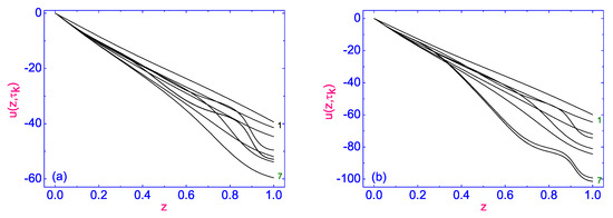
Figure 8.
(a) The relaxation of the velocity field to its stationary distribution across the HAN microfluidic channel composed of molecules and under the effect of SS (∼10 Pa) for different times starting from (curve 1) to (curve 7). Here, . (b) The same as in (a) but with SS (∼15 Pa) and (∼0.1 s). Here, , and is equal to .
According to our calculations, SS produces the velocity field directed in the negative direction, and its effect on the director distribution across the HAN microfluidic channel is so strong that, in the middle part of the nematic channel, the director field is directed almost orthogonally to both boundaries (the biggest value of the polar angle is 180 (see Figure 7b). The relaxation process of the velocity field is characterized by the growth of upon increasing , before achieving the stationary distribution across the microsized HAN channel. This distribution is characterized by the maximum value of on the upper bounding surface (), and the hydrodynamic flow is directed parallel to both bounding surfaces in the negative direction. The maximum value of the dimensionless velocity in the HAN channel on the upper bounding surface at the final stage of the relaxation process is equal to ∼60.4 (∼1.9 mm/s) at (∼10 Pa) (see Figure 8a) and ∼102 (∼3.14 mm/s) at (∼15 Pa) (see Figure 8b). In the case when the heat flux across the upper surface is restricted ( nW/), we deal with the almost linear increase of across the HAN channel from the temperature at the lower ((∼307 K)) to the value at the upper boundary . The relaxation of the dimensionless temperature at the upper boundary of the HAN microfluidic channel consisting of molecules to its stationary value for three values of SS, (curve 1), (curve 2), and (curve 3), is shown in Figure 9.

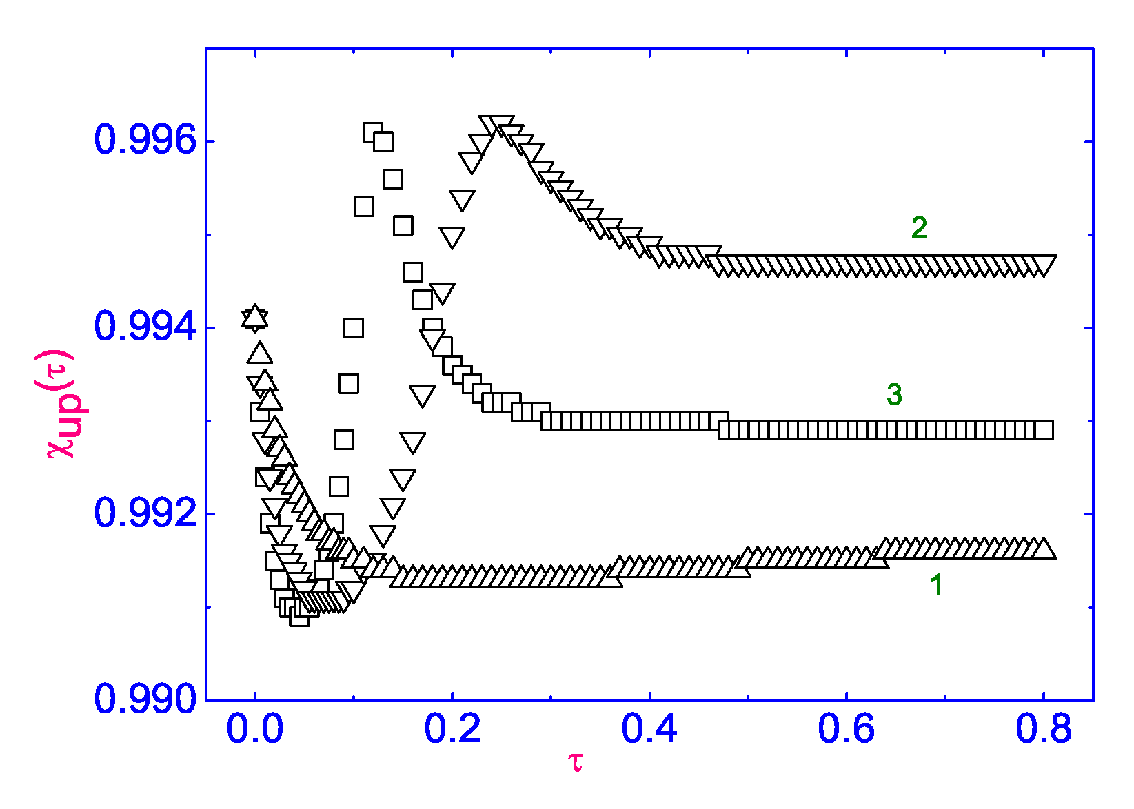
Figure 9.
Plot of relaxation of the dimensionless temperature on the upper boundary of the HAN microfluidic channel to its stationary value for three values of SS (curve 1), (curve 2), and (curve 3). The curves correspond to the heat flux nW/, directed across the upper boundary.
The calculations show that the relaxation process up to its stationary value at both lower values of SS (∼−10 Pa) and (∼−15 Pa) is characterized by the oscillatory behavior of , before achieving (∼311.3 K) and (∼310.8 K), respectively, whereas is equal to (∼310.4 K). Thus, the highest temperature difference (∼4.3 K), which initially was equal to zero, is built in the HAN channel under the influence of SS (∼−10 Pa). Note that, in all these cases, the dimensionless temperature at the lower boundary is kept constant (∼307 K), and the vertical temperature gradient is created over the HAN channel, directed towards the warmer upper boundary.
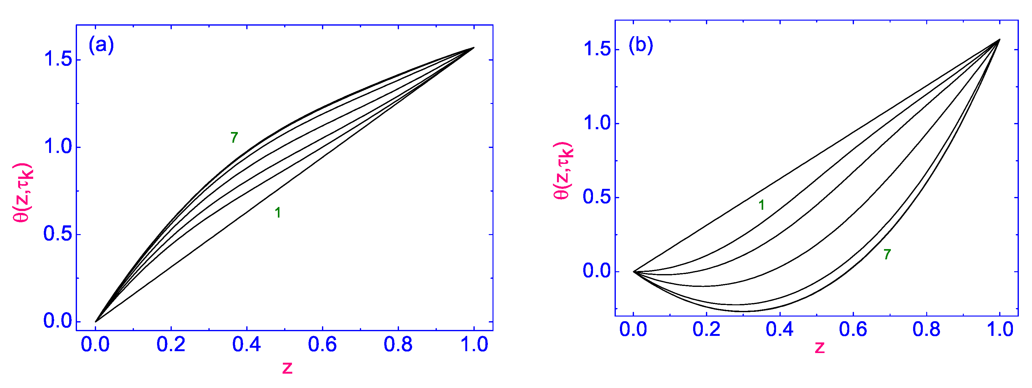
The effect of SS , applied both in the positive (∼5 Pa) (see Figure 10a) (case I) and negative (∼−5 Pa) (see Figure 10b) (case II) directions on the evolution of the director field to its stationary orientation in the microsized HAN channel, composed of laminar type nematic (), is shown in Figure 10. This evolution is described by the polar angle , and the calculations are given for different times starting from (curve 1) to (∼0.08 s) (curve 7).
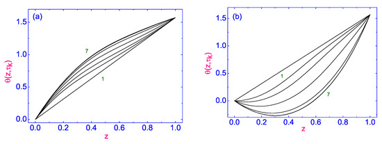
Figure 10.
(a) The evolution of the polar angle to its stationary distribution across the HAN microfluidic channel composed of molecules and under the effect of two values of SS : (a) the first is equal to (∼5 Pa), whereas (b) the second is equal to (∼−5 Pa). The different times started from (curve 1) to (∼0.08 s) (curve 7), whereas is equal to . Here, .
First, the effect of SS on the evolution of the director field is manifested in the qualitative difference in the polar angle profiles for cases I (see Figure 10a) and II (see Figure 10b). In case I, we have convex profiles, when the polar angle increases monotonically from 0 to , whereas in case II, the polar angle decreases monotonically from 0 to , with a subsequent increase in the value of ∼ at the upper boundary of the HAN channel.
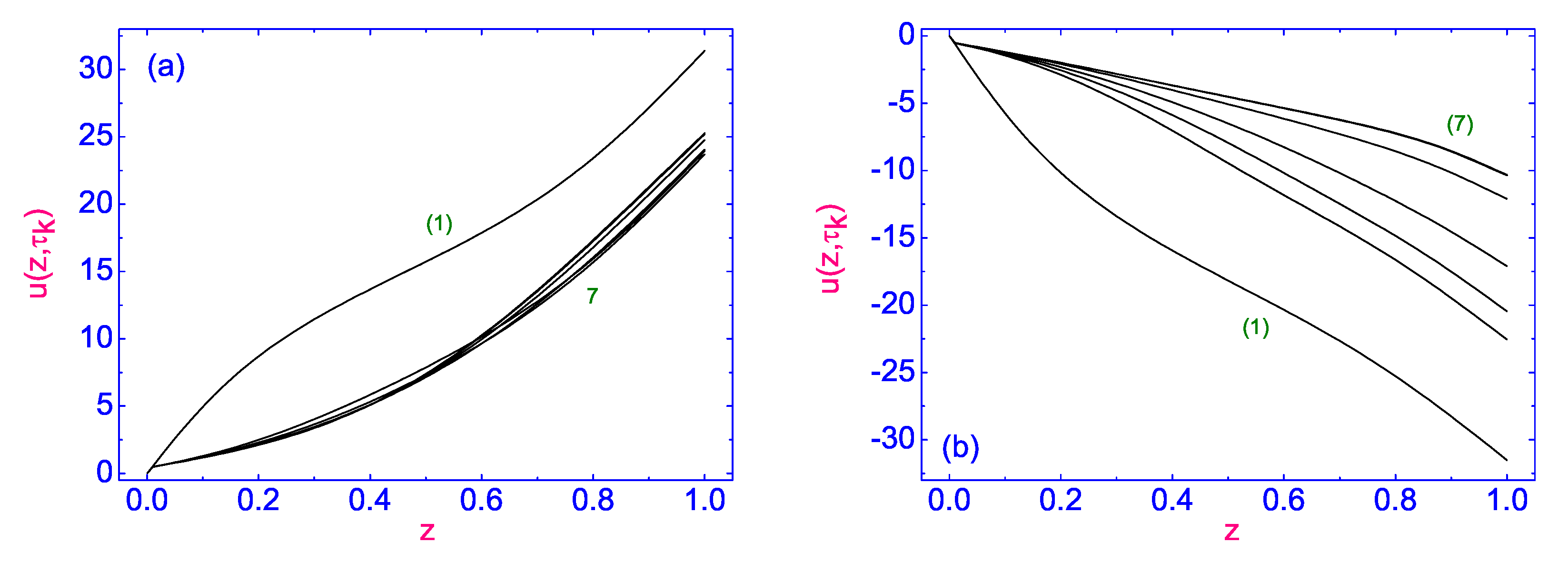
Second, the effect of SS applied both in the positive (case I) and negative (case II) directions on the evolution of the velocity field is mainly quantitative (see Figure 11a,b), where the velocity increases from zero () at the lower boundary of the channel to the value (∼0.7 mm/s) at the upper boundary in case I and from zero () at the lower boundary of the channel to the value (∼−0.32 mm/s) at the upper boundary in case II.
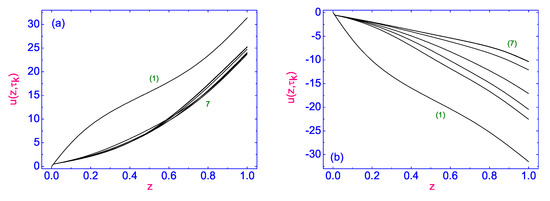
Figure 11.
The evolution of the velocity field to its stationary distribution across the HAN microfluidic channel composed of 5CB molecules and under the effect of two values of SS : (a) the first is equal to (∼5 Pa), whereas (b) the second is equal to (∼−5 Pa), respectively. Different times the same as in Figure 10.
3. A Role of a Flow in a Temperature Gradient Formation across a HAN Channel
The purpose of this paragraph is to show the simple way the temperature gradient can be built up across the HAN channel under the action of the hydrodynamic flow in the framework of the classical Ericksen–Leslie theory [10,11] while accounting for the entropy balance equation [12]. We consider the thermal conductivity regime, which assumes that the temperature at the lower boundary is kept constant whereas, at the upper boundary, where it was assumed that the heat flux is vanished, it must satisfy the boundary conditions
As a result, the temperature difference, being initially equal to zero, grows by up to the maximum possible value , corresponding to the nematic phase. The answer to the question of which restricted surfaces are cooler or warmer depends on the direction of the hydrodynamic flow .
We consider a nematic system consisting of asymmetric polar molecules, such as , which are confined between two solid surfaces that impose a preferred orientation of the average molecular direction on the restricted surfaces, for instance, homeotropic on the lower boundary surfaces and planar on the upper bounding surfaces. Therefore, we describe the HAN channel under the influence of the temperature gradient parallel to the unit vector . Here, is a unit vector directed from the lower substrate to the upper one (see Figure 1). The coordinate system defined by this task assumes that the director lies in the plane (or in the plane) (see Figure 1).
Assuming that the temperature gradient is due to the growth of the temperature difference at the HAN boundaries under the action of the hydrodynamic flow changes only in the direction z, we can assume that the components of the director as well as other physical quantities depend only on the z coordinate. Here, denotes the polar angle, i.e., the angle between the direction of the director and the normal to the bounding surfaces.
Assuming that we deal with an incompressible fluid, the dimensionless hydrodynamic equations corresponding to the torque balance (see Equation (9)) and the linear moment balance (see Equation (10)) equations as well as the entropy balance equation (see Equation (12)) take the following form [23]:
where and are the hydrodynamic and elastic functions, respectively; is the ST component; the set of the LC parameters is the same as in Section 3; is the dimensionless time; and is the dimensionless distance away from the lower boundary of the HAN channel. Note that the overbars in the space variable z in the last three Equations (21)–(23) have been eliminated.
Now, consider that the HAN system confined between two solid surfaces when the director is strongly anchored to these boundaries, homeotropically to the lower and homogeneously to the upper boundaries,
whereas the velocity on these boundaries must satisfy the no-slip boundary condition,
Now, the temperature field in the HAN channel confined between two solid boundaries when the temperature at the lower boundary is kept constant but where, at the upper boundary, it was assumed that the heat flux vanished must satisfy the boundary conditions [22]
The set of parameters that are involved in Equations (21)–(23) are equal to , , , and . Using the fact that , , and , the linear moment balance (22) and the entropy balance (23) equations can be considerably simplified. Thus, the whole left-hand side of Equations (22) and (23) can be neglected, and these equations take the following form:
where , , is the function that does not depend on z and is fixed by the boundary conditions and where
To be able to observe the formation of the temperature difference across the HAN channel under the effect of the stationary hydrodynamic flow, the stationary analog of the Equation (21) was considered when . In this case, the dimensionless temperature across the hybrid aligned nematic channel is given by [23]
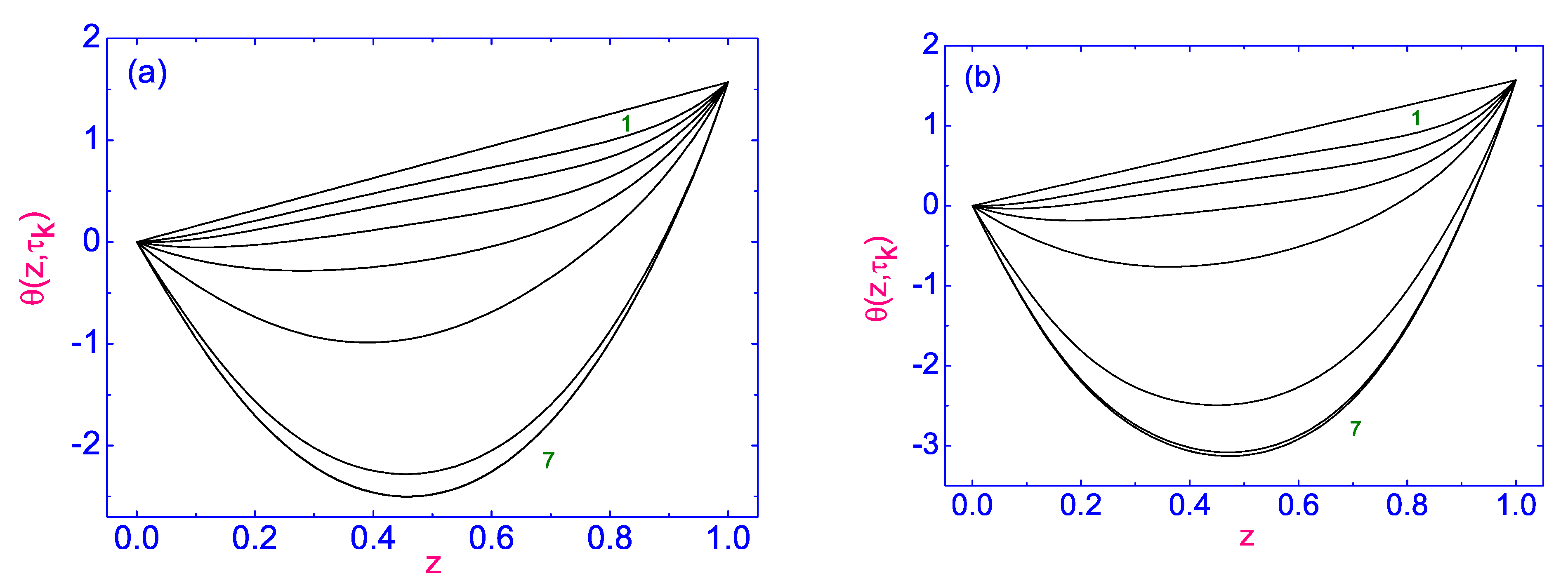
where , , and . The formation of the temperature difference across the HAN channel under the influence of the stationary flow with a triangular sharp profile
was investigated by the standard numerical relaxation method [23], and the results are shown in Figure 12a,b. The relaxation criterion for calculating procedure was chosen to be equal to and then, the numerical procedure was carried out until a prescribed accuracy was achieved.
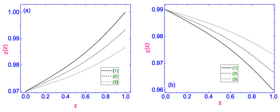
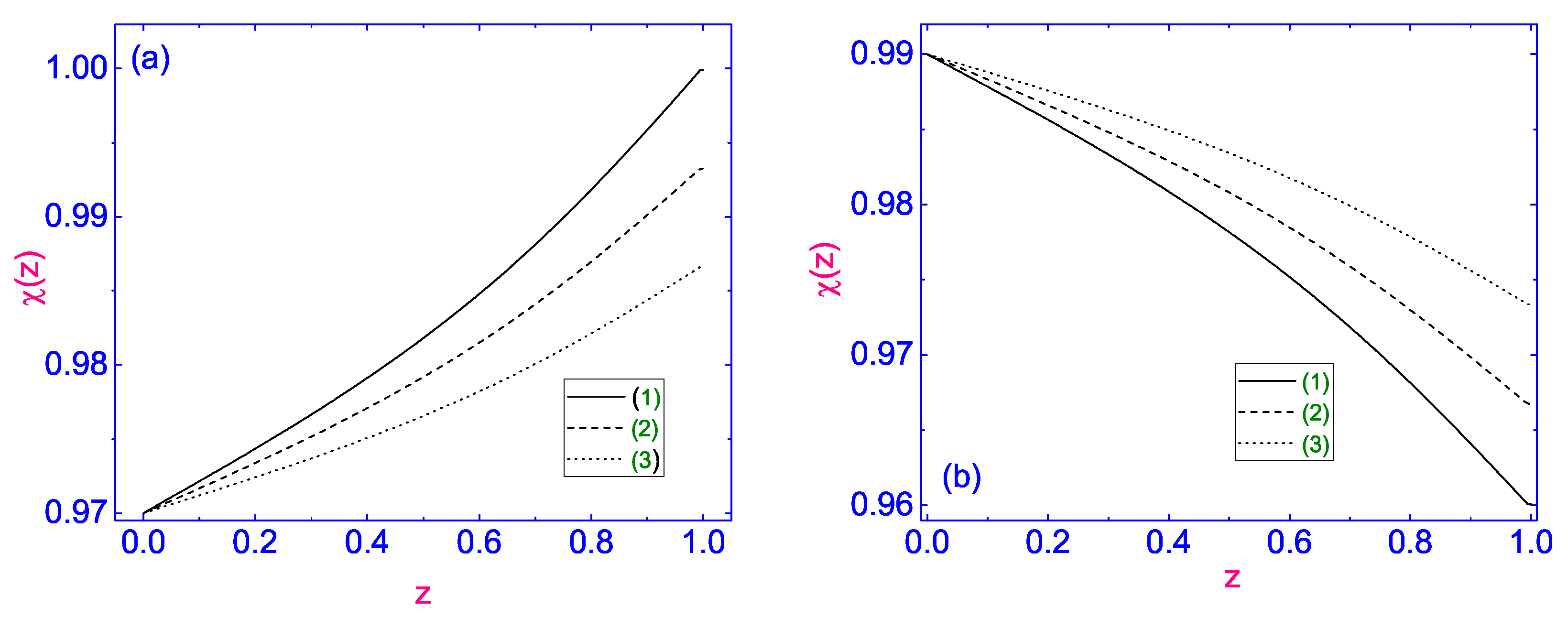
Figure 12.
(a) The distance z dependence of the temperature over the HAN channel under the effect of the stationary flow , with a triangular profile, for a number of values of [23]: (curve 1), (curve 2), and (curve 3). In this case, the vector is in the positive direction. (b) The same as in (a), but is in the negative direction.
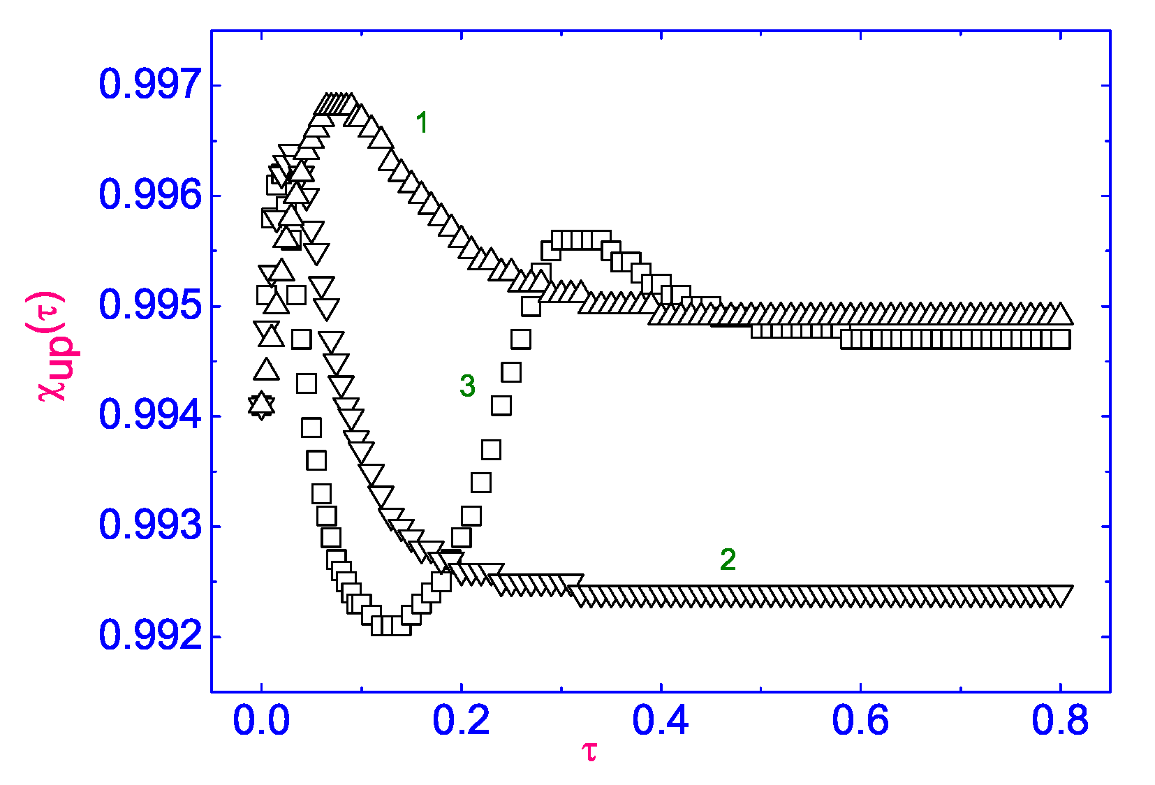
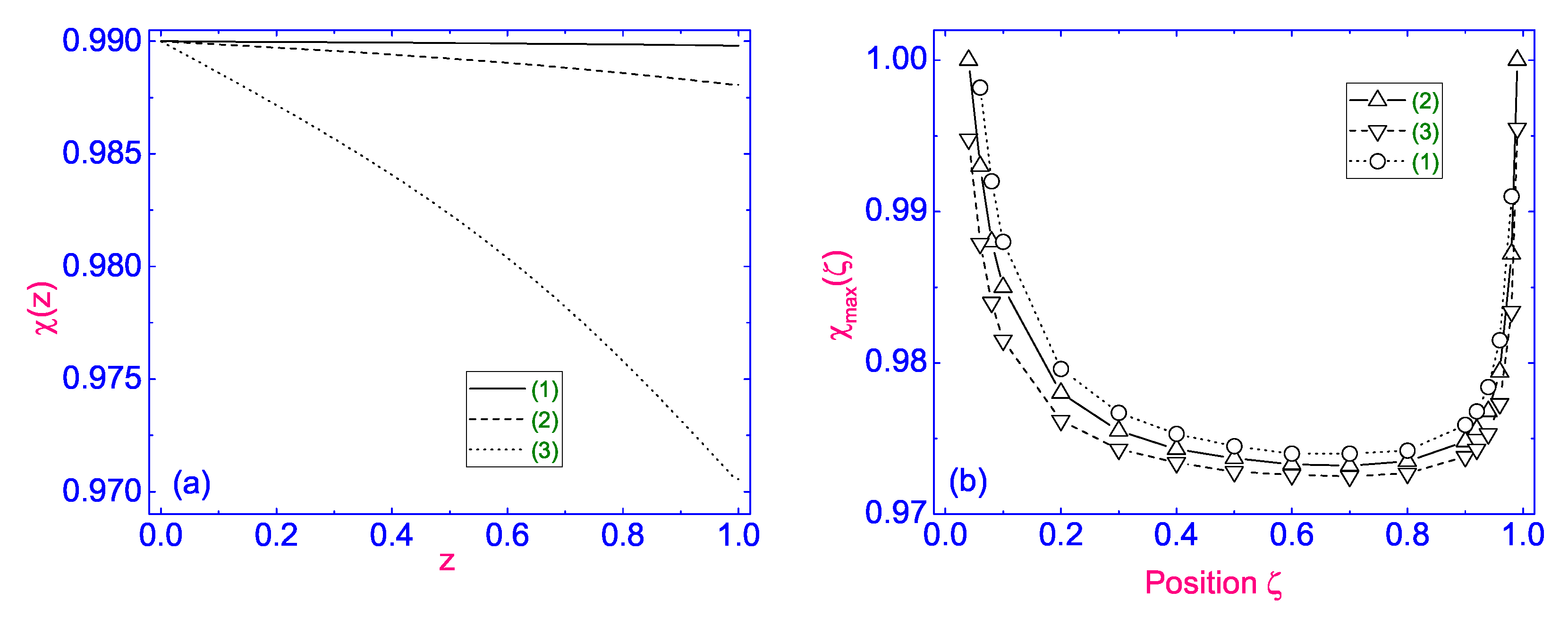
When the stationary hydrodynamic flow is directed in the positive direction (see Figure 12a), and the temperature at the lower boundary of the HAN channel keeps a constant value (∼298 K), across the nematic sample, a vertical temperature gradient directed to warmer upper boundary forms. The highest temperature difference (∼9 K), which was initially equal to zero, is built in the HAN channel under the influence of the hydrodynamic flow , where the magnitude of the factor is equal to (∼1.2 nm/s) (see Figure 12a, curve (1)). The rest curves (2) and (3) correspond to (∼1 nm/s) and (∼0.7 nm/s), respectively. In the case of the reverse direction (see Figure 12b), the temperature on the upper bounded surface remains constant (∼304 K), while the lower surface cools to (∼295 K), which is close to the nematic-solid phase transition temperature at (curve (1)). In all of these cases, (∼0.98) is close to the upper boundary of the HAN channel. The value of has a huge influence on the location of the maximum of . In the case where is placed in the middle part of the nematic channel, (see Figure 13a), the temperature difference, which was initially equal to zero, increases to (∼0.3 K) at the value of and only with the increase in by up to a two order of magnitude, from up to (∼0.1 μm/s); that difference in temperature increases to a few degrees (∼6 K). The effect of the position on the value of the maximum temperature difference when a constant temperature is kept at (∼298 K) at the lower boundary for a number of values of the hydrodynamic velocities is shown in Figure 13b. Notes that the velocity and the temperature at the boundaries must satisfy the boundary conditions Equations (24) and (25), respectively. We found that the value of is sensitive to the position of and shows an increase in the magnitude of the highest temperature difference when is close to both boundaries of the HAN channel. This behavior of is dictated by Equation (29). Indeed, in the case of the stationary flow, the value of the shear rate shift increases to infinity in the vicinity of the bounding surfaces, when the position of or 1. Physically, this means that only the stationary flow with a triangular sharp profile and a maximum position near boundaries can create the highest temperature difference in the hybrid aligned nematic channel of several degrees. With another hydrodynamic flow with profiles that cannot demonstrate the sharp growth of , the same result can be achieved only by using the “high-speed” hydrodynamic flow ∼0.1 μm/s.
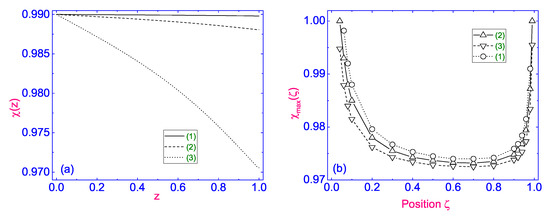
Figure 13.
(a) The distance z dependence of the temperature for the stationary flow in the negative direction and calculated for a number of [23]: (curve 1), (curve 2), and (curve 3). (b) Dependence of vs. position of for a number of : (curve 1), (curve 2), and (curve 3).
It was shown by the Brewster angular spectroscopy (BAS) method that the hydrodynamic flow of arachidic (eicosanoic) acid through the narrow channel with the width of ∼0.1 μm and with the triangular velocity profile at a shear rate of more than 0.2 s−1 at different values of surface pressure can be achieved [22]. It has also been shown that, as the flow rate increases, the velocity profile gradually becomes sharper, eventually becoming triangular. In a typical fluid, such a profile would indicate shear thickening. If this is the case, we do not exclude the possibility of extending the BAS method to the case of the abovementioned nematic system.
4. Conclusions
This section discusses some recent numerical advances in predicting the structural and hydrodynamic behavior of thermally excited flow in microfluidic hybrid aligned nematic (HAN) channels. Despite the fact that certain quantitative and qualitative advances have been made in the hydrodynamic description of relaxation processes in microsized nematic channels under the effect of a temperature field, there are still a number of questions concerning the temperature gradient formation across these channels. It is shown that, under the influence of the temperature gradient, the horizontal nematic layer, initially at rest, starts moving in the horizontal direction when heated both from below and from above. In the case of strong homeotropic and planar anchorings at the boundaries, the equilibrium distribution of the velocity field over the HAN channel is characterized by a sharp increase in the absolute value of in the vicinity of the boundary with the planar anchoring [7]. This result, in turn, leads to a number of questions. Is it possible for a temperature difference to occur between two boundaries of the HAN microfluidic channel as a result of the stationary hydrodynamic flow distribution of the flow across the channel or by applying the SS to the boundaries of this channel? Alternatively, in more general terms, how does depend on or ?
The second set of questions is related to the study of the influence of the microscopic width of the LC channel (confining) on the nature of the orientation dynamics of such an LC system. First, it should be noted that, in our case, the shear flow is formed under conditions of strong anchoring of the director field to the boundaries of the LC channel despite the fact that we deal with a microsized channel. Thus, confining also plays a crucial role in the formation of orientation dynamics in such an LC system. Apparently, with an increase in the width of the LC channel, the nature of the orientation dynamics of the director field changes in the direction of continuous rotation of the director, as we described in the article [19].
The absence of continuous rotation of the director field in the tumbling regime is actually due to the combined effect of both anchoring and the size of the HAN channel. Undoubtedly, further investigation of changes in the orientation dynamics in a microscopic LC channel under the influence of a shear stress applied to one of the boundaries of the LC channel as the channel width increases will be continued.
The above numerical results show that both the stationary flow with a triangular velocity profile and SS applied to the boundaries of the HAN channel can, under certain conditions, overcome the viscous, elastic, thermomechanical, and anchoring forces and cause a temperature gradient across this channel, with the maximum absolute temperature difference being up to several degrees.
This once again shows that the macroscopic description of the nature of the hydrodynamic flow of an anisotropic liquid subtly senses the microscopic structure of an LC material.
We believe that the present investigation can shed some light on the problem of precise handling of microvolume LC drops, which requires self-contained micropumps.
Author Contributions
Writing—original draft preparation and editing, I.Ś.; writing—original draft preparation and editing and supervision, A.V.Z. All authors have read and agreed to the published version of the manuscript.
Funding
This research received no external funding.
Data Availability Statement
Not applicable.
Conflicts of Interest
The authors declare no conflict of interest.
References
- Schenning, A.P.H.J.; Crawford, G.P.; Broer, D.J. Liquid Crystal Sensors; CRC Press, Taylor and Francis Group: Boca Raton, FL, USA, 2018. [Google Scholar]
- Zakharov, A.V.; Maslennikov, P.V.; Pasechnik, S.V. Electrically driven nematic flow in microfluidic devices containing a temperature gradient. Phys. Rev. 2020, 101, 062702. [Google Scholar] [CrossRef] [PubMed]
- Zakharov, A.V.; Maslennikov, P.V.; Pasechnik, S.V. Electrically driven nematic flow in microfluidic capillary with radial temperature gradient. Phys. Rev. 2021, 103, 012702. [Google Scholar]
- Squires, T.M.; Quake, S.R. Microfluidics: Fluid physics at the nanoliter scale. Rev. Mod. Phys. 2005, 77, 977–1026. [Google Scholar] [CrossRef] [Green Version]
- Schoch, R.B.; Han, J.; Renaud, P. Transport phenomena in nanofluidics. Rev. Mod. Phys. 2008, 80, 839–883. [Google Scholar] [CrossRef] [Green Version]
- Akopyan, R.S.; Zeldovich, B.Y. Thermomechanical effects in deformed nematics. Sov. Phys. JETP 1984, 87, 1660–1669. [Google Scholar]
- Zakharov, A.V.; Vakulenko, A.A. Influence of the flow on the orientational dynamics induced by temperature gradient in nematic hybrid-oriented cells. J. Chem. Phys. 2007, 127, 084907. [Google Scholar] [CrossRef] [PubMed]
- Śliwa, I.; Zakharov, A.V. Heat driven flow in microsized nematic volumes: Computational studies and analysis. Symmetry 2021, 13, 459. [Google Scholar] [CrossRef]
- Akopyan, A.R.; Alaverdian, R.B.; Santrosian, E.A.; Chilingarian, Y.S. Thermomechanical effects in the nematic liquid crystals. J. Appl. Phys. 2001, 90, 3371–3376. [Google Scholar] [CrossRef]
- Ericksen, J.L. Anisotropic Fluids. Arch. Ration. Mech. Anal. 1960, 4, 231–237. [Google Scholar] [CrossRef]
- Leslie, F.M. Some constitutive equations for liquid crystals. Arch. Ration. Mech. Anal. 1968, 28, 265–283. [Google Scholar] [CrossRef]
- Landau, L.D.; Lifshitz, E.M. Fluid Mechanics; Pergamon: Oxford, UK, 1987. [Google Scholar]
- Loisyu, A.; Eggers, J.; Liverpool, T.B. Active suspensions have nonmonotonic flow curves and multiple mechanical equilibria. Phys. Rev. Lett. 2018, 121, 018001. [Google Scholar] [CrossRef] [Green Version]
- Negro, G.; Carenza, L.N.; Lamura, A.; Tiribocchini, A.; Gonnella, G. Rheology of active polar emulsions; from linear to unidirectional and inviscid flow, and intermittent viscosity. Soft Matter 2019, 15, 8251–8265. [Google Scholar] [CrossRef] [Green Version]
- Markovich, T.; Tjhung, E.; Cates, M.E. Shear-induced first-order transition in polar liquid crystals. Phys. Rev. Lett. 2019, 123, 088004. [Google Scholar] [CrossRef] [Green Version]
- Eber, N.; Janossy, I. An experiment on the thermomechanical coupling in cholesterics. Mol. Cryst. Liq. Cryst. 1982, 72, 233–238. [Google Scholar] [CrossRef]
- Archer, L.A.; Larson, R.G. A molecular theory of flow alignment and tumbling in shear nematic liquid crystals. J. Chem. Phys. 1995, 103, 3108–3111. [Google Scholar] [CrossRef]
- Zakharov, A.V.; Dong, R.Y. Two shear flow regimes in nematic liquid crystals: Near a charged surface and in the bulk. J. Chem. Phys. 2002, 116, 6348–6353. [Google Scholar] [CrossRef]
- Zakharov, A.V.; Thoen, J. Pretransitional anomalies in the shear flow near a second-order nematic- smectic—A phase change. Phys. Rev. 2004, 69, 051709. [Google Scholar]
- Pieranski, P.; Guyon, E. Instability of certain shear flows in nematic liquids. Phys. Rev. 1974, A9, 404–417. [Google Scholar] [CrossRef]
- Chmielewski, A.G. Viscosity coefficients of some nematic liquid crystals. Mol. Cryst. Liq. Cryst. 1986, 132, 339–352. [Google Scholar] [CrossRef]
- Kurnaz, L.M.; Schwartz, D.K. Channel flow in a Langmuir monolayer: Unusual velocity profiles in a liquid-crystalline mesophase. Phys. Rev. 1997, E56, 3378–3384. [Google Scholar] [CrossRef]
- Zakharov, A.V.; Vakulenko, A.A. Temperature gradient formation across a nematic hybrid-oriented film. Chem. Phys. Lett. 1997, 454, 80–84. [Google Scholar] [CrossRef]
- Zakharov, A.V.; Maslennikov, P.V. Laser-excited motion of liquid crystals confined in a microsized volume with a free surface. Phys. Rev. 2017, 96, 052705. [Google Scholar] [CrossRef] [PubMed]
- Madhusudana, N.V.; Pratibha, R.P. Elasticity and orientational order in some cyanobiphenyls: Part IV. Reanalysis of the data. Mol. Cryst. Liq. Cryst. 1982, 89, 249–257. [Google Scholar] [CrossRef]
- Jamee, P.; Pitsi, G.; Thoen, J. Systematic calorimetric investigation of the effect of silica aerosils on the nematic to isotropic transition in heptylcyanobiphenyl. Phys. Rev. 2002, 66, 021707. [Google Scholar] [CrossRef] [PubMed]
- Marinelli, M.; Ghosh, A.K.; Mercuri, F. Small quartz silica spheres induced disorder in octylcianobiphenyl (8CB) liquid crystals: A thermal study. Phys. Rev. 2001, 63, 061713. [Google Scholar]
- Berezin, I.S.; Zhidkov, N.P. Computing Methods, 4th ed.; Clarendon: Oxford, UK, 1965. [Google Scholar]
Publisher’s Note: MDPI stays neutral with regard to jurisdictional claims in published maps and institutional affiliations. |
© 2021 by the authors. Licensee MDPI, Basel, Switzerland. This article is an open access article distributed under the terms and conditions of the Creative Commons Attribution (CC BY) license (https://creativecommons.org/licenses/by/4.0/).