Article

Design and Catalytic Behaviour of Hosted in Activated Carbon Foam CoxZn1−xFe2O4 Ferrites

1
Institute of Organic Chemistry with Centre of Phytochemistry, Bulgarian Academy of Sciences, 1113 Sofia, Bulgaria
2
Institute of Catalysis, Bulgarian Academy of Sciences, 1113 Sofia, Bulgaria
3
Institute of General and Inorganic Chemistry, Bulgarian Academy of Sciences, 1113 Sofia, Bulgaria
4
Institute of Optical Materials and Technologies, Bulgarian Academy of Sciences, 1113 Sofia, Bulgaria
*
Author to whom correspondence should be addressed.
Symmetry 2021, 13(8), 1532; https://doi.org/10.3390/sym13081532
Submission received: 15 July 2021 / Revised: 12 August 2021 / Accepted: 13 August 2021 / Published: 20 August 2021
(This article belongs to the Special Issue Heterogeneous Catalysis: Topics and Advances)

Abstract

:
Carbon foams with different surface functionality and tailored texture characteristics were prepared from mixtures containing coal tar pitch and furfural in different proportions. The obtained materials were used as a host matrix for the preparation of zinc- and cobalt-mixed ferrite nanoparticles. The texture, morphology, phase composition, and the related redox and catalytic properties of the obtained composites were characterized by low-temperature nitrogen physisorption, XRD, SEM, HRTEM, FTIR, Mössbauer spectroscopy, TPR and catalytic decomposition of methanol to syngas. The impact of the carbon support on the formation of Co- and Zn-mixed ferrites was discussed in detail using KIT-6 silica-based modifications as reference samples. The catalytic behavior of the ferrites was considered in a complex relation to their composition, morphology, location in the porous matrix and metal ions distribution in the spinel sub-lattices. The higher amount of furfural in the carbon foam precursor promoted the formation of cobalt-rich, more accessible and highly active methanol decomposition to syngas spinel particles.

1. Introduction

In the last century the nanoscale chemical engineering has gained a particular scientific, industrial and ecological interest [1,2,3,4]. Simple control of the magnetic, optic, electronic and catalytic properties of nanosized materials has been demonstrated by tuning of their composition, size, shape and morphology, which successfully expanded the fields of their application [5,6,7,8,9]. Ferrites belong to the magnetic nanomaterials and among them, spinel ferrites with general formula MFe2O4, are widely used for waste water treatment, electrochemical energy storage, magnetic devices, drug delivery systems and antibacterial agents [7,8,10,11,12]. Spinel ferrites are easy to regenerate; they are stable and inexpensive and their attractive properties could be enhanced by doping with different metals [11]. However, up to this moment, only copper, cobalt, nickel, zinc and several mixed-metal and core-shell ferrites have been applied in the catalytic reactions, mainly in the processes of synthesis and destruction of organic compounds [7,13,14,15,16].
The ideal spinel structure consists of cubic unit cells with 64 and 32 available tetrahedral and octahedral sites, of which only 8 and 16 sites, respectively, are occupied by cations [6,16]. Based on the position of the cations in the lattices, spinel ferrites can be categorized into three types. In the normal spinel ferrites, such as ZnFe2O4, the M2+ cations occupy all the tetrahedral sites and the Fe3+ ions are situated on the octahedral ones. In the inverse spinel, like magnetite, half of the Fe3+ ions occupy all the tetrahedral sites and both M2+ and Fe3+ ions are in the octahedral environment. In the mixed spinel ferrite, the M2+ and Fe3+ ions are randomly distributed on the tetrahedral and octahedral positions. Depending on the synthesis protocol, CoFe2O4 could be synthesized as normal or inverse spinel ferrite [17,18]. Generally, zinc-substituted cobalt ferrites with general formula CoxZn1−xFe2O4, have an inverse spinel structure, where the cobalt ions are within the octahedral position, while iron and zinc ions are distributed between the tetrahedral and octahedral sites [10,19,20,21,22,23]. It was well-established that the catalytic properties of the spinel ferrites are related to the cations situated on the octahedral sites, because they are considerably exposed in the crystallites [16]. The synthesis method and the concentration of the dopant could strongly affect the texture, morphology and cation distribution in the spinel ferrites [19,20]. Various techniques, such as sol-gel, auto-combustion, hydrothermal procedure, forced hydrolysis and co-precipitation, were used for the CoxZn1−xFe2O4 ferrites preparation [22].
The application of porous supports as a host matrix is a well-known approach for the stabilization of metal oxide particles at the nanoscale. Carbon materials are a typical example of porous supports, the texture and surface characteristics of which could be easily adjusted using diverse precursors and preparation methods [23,24,25,26,27,28]. In our previous investigation, a strong effect of activated carbon support on the formation of ZnFe2O4 [29,30,31] and NixZn1−xFe2O4 [32] ferrite nanoparticles was reported. The potential of the ferrite/activated carbon composites as catalysts in methanol decomposition was also demonstrated. Carbon foam is a new class of porous materials, which can be easily prepared by carbonization of low-cost materials, such as polymers, biomass, coal or petroleum tar pitch [32,33,34,35,36,37,38,39]. Carbon foam has a specific, highly interconnected porous structure. It is developed by macropores, surrounded by carbon wall (cells) and holes in the carbon wall, connecting the neighboring cells (windows) as well as a lot of micropores, mesopores and small macropores in the carbon wall [40]. The precursor characteristics and the preparation method used affect the structure of the obtained material [37,41,42,43]. Stoycheva et al. [44] reported an easy and economically viable procedure for the preparation of carbon foam. The authors used thermo-oxidative pre-treatment of coal tar pitch in the presence of mineral acids, avoiding the need for high pressure and a “stabilization” step during the synthesis. Development of additional porosity in the carbon foam by steam activation with preservation of the morphology of the pristine material was demonstrated in [41]. Recently, carbon foam has been intensively studied for gas storage and electromagnetic shielding, as a support in electrochemical capacitor, in heterogeneous catalysis and electro catalysis [34,42,43,44,45,46]. Velasco et al. [47] explored carbon foam/titania composite as a catalyst for phenol degradation. Varila et al. [48] used carbon foam as a catalyst support for batch hydro treatment of furfural to produce methyl furan. However, to the best of our knowledge, no data for CoxZn1−xFe2O4-modified carbon foam have been published yet.
The aim of this study is to obtain knowledge for the formation of CoxZn1−xFe2O4 ferrites with diverse composition (x varied between 0 and 1) into a carbon foam host matrix. For this purpose, different physicochemical techniques, such as X-ray Diffraction (XRD), Transmission Electron Microscopy (TEM), Infrared (FTIR) and Mössbauer spectroscopy and Temperature Programmed Reduction-Thermo-Gravimetric analyses (TPR-TG) in hydrogen, were used. The catalytic properties of the composites were studied in methanol decomposition. Recently, methanol has been intensively investigated as safe and abundant hydrogen carrier and methanol decomposition has been reported as easy and effective approach for hydrogen release from methanol, especially for the application in portative and mobile devices [49,50,51,52,53,54]. In order to increase the environmental and economic impact of the study, carbon foam was prepared from cheap and waste industrial sources, such as coal tar pitch and furfural using a thermo-oxidative pre-treatment in the presence of a nitric acid method [55]. For proper understanding of the obtained results, similar ferrite modifications of KIT-6 mesoporous silica were studied as well. It was illustrated that the morphology, phase composition and the distribution of the metal ions in the CoxZn1−xFe2O4 ferrites and the related redox and catalytic properties could be simply controlled by the Co/Zn ratio and the variation of the composition of the carbon foam precursor.

2. Materials and Methods

2.1. Materials

A commercial furfural (softening point 345 K) and coal tar pitch in 40:60 and 60:40 wt.% proportions were used as a precursor for the preparation of carbon foams, denoted as ACF40 and ACF60, respectively [55]. The coal tar pitch was heated at 393 K until melting conditions and was then mixed and heated up to 393 K furfural under stirring. The obtained mixture was treated with HNO3 (68 wt.%) until solidification. After washing with hot distilled water, the solid product was heated up to 873 K (heating rate of 15 K·min−1) in nitrogen atmosphere and then, subjected to activation with water vapor at 1073 for 1 h. In order to clarify the effect of the carbon supports and to precise the interpretation of the obtained results by different methods, KIT-6 mesoporous silica was used as a reference support. The KIT-6 silica was prepared using Pluronic 123 as a structure directing agent and decomposition of the template took place at 823 K for 6 h in air, following the procedure described in [56]. A modified incipient wetness impregnation technique was used for the support modification. For this purpose, the obtained carbon and silica supports were at first treated under vacuum in a glass pot and then sprayed with an appropriate volume of methanol solution of Fe(NO3)3·9H2O, Co(NO3)2·6H2O and Zn(NO3)2·6H2O. After drying at room temperature overnight, the composites were heated in nitrogen at 773 K for 2 h. The total metal content in the samples was 8 wt.% and the Fe/(Co + Zn) molar ratio was 2. The samples were denoted as CoxZn(1 − x)S, where x/(10 − x) was the Co/Zn molar ratio and S was the type of the support (ACF40, ACF60 or KIT-6).

2.2. Methods of Characterization

Low-temperature nitrogen physisorption analyses were performed on a Quantachrome Instruments NOVA 1200e (Quantachrome, Boynton Beach, FL, USA) apparatus. A Brunauer Emmett Teller (BET) Equation was used for specific surface area evaluation; the total pore volume was elucidated at 0.99 relative pressure; Dubinin–Astakhov method was applied for the micropore volume calculation and a Non-Localized Density Functional Theory method was used for the mesopore size distribution determination.
XRD patterns were obtained on a Bruker D8 Advance diffractometer (Bruker AXS GmbH, Bremen, Germany) using Cu Kα radiation and a LynxEye detector (2θ step = 0.02°; counting time = 17.5 sper step). The mean coherent domain size was calculated from the parameters of Lorentz component of the Voigt function using the Topas-4.2 software [57]. The transmission electron microscopic images were done on a JEOL JEM 2100 microscope (JEOL Ltd., Tokyo, Japan) (accelerated voltage = 200 kV). For the sample preparation, a standard copper grid, covered with amorphous carbon, was applied. The Mössbauer spectra were recorded on a Wissel (Wissenschaftliche Elektronik GmbH, Starnberg, Germany) electromechanical spectrometer at room temperature or under the temperature of liquid nitrogen (LNT). A 57Co/Rh (activity ≈ 10 mCi) source and α-Fe standard as well as a WinNormos software for the picks fitting were used.
The FTIR spectra were collected on a Bruker Vector 22 FTIR spectrometer with resolution 1 cm−1 using 64 scans.
The TPR/TG analyses were performed on a simultaneous thermal analyzer—STA 449 F3 Jupiter (NETZSCH-Gerätebau GmbH). Typically, about 15 mg of the sample was treated in 50 mL·min−1 flow of 5% H2 in Ar with heating rate of 5 K·min−1 up to 773 K.
The amount of various acidic oxygen-containing functional groups was determined by Boehm’s method using aqueous solutions of NaHCO3, Na2CO3, NaOH, and C2H5ONa, according to the procedure described in [58]. The total amount of basic sites was determined with 0.05 N HCl as described in [59].

2.3. Catalytic Test

The catalytic experiments were performed in a flow type apparatus, equipped with a thermostat at 373 K saturator with methanol, gas-flow and temperature regulators and gas chromatograph (GC) for analyses. Typically, 55 mg of each catalyst were pre-treated in situ in an argon flow at 373 K for 1 h. Then, a flow mixture of methanol and argon (methanol partial pressure = 1.57 kPa, flow velocity = 50 mL·min−1) was introduced into the reactor and. the temperature was increased up to 773 K (heating step = 20 K). At each temperature, the output gas was detected by a SCION 456-GC apparatus, equipped with flame ionization and thermo-conductivity detectors and PORAPAC-Q column. An absolute calibration method and a carbon-based material balance was used for the elucidation of methanol conversion and product distribution at different temperatures.

3. Results and Discussion

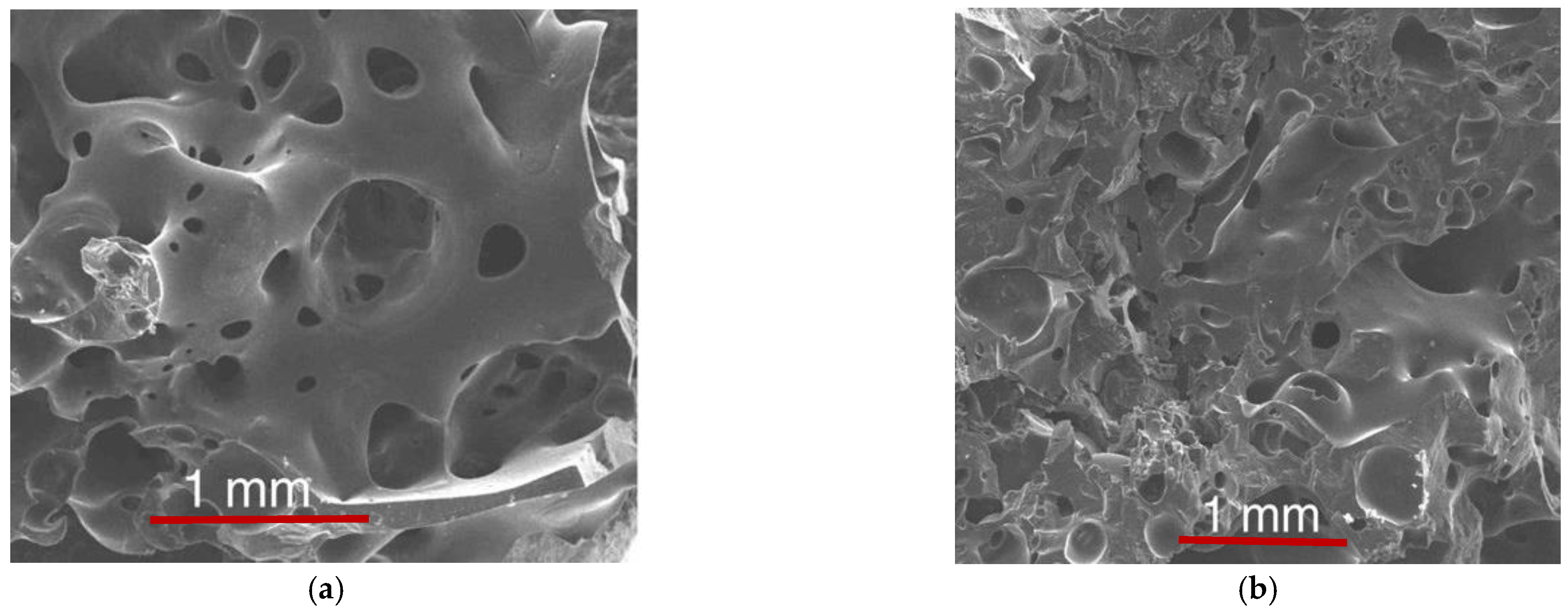
3.1. Catalyst Supports Characterization

XRD patterns of pristine carbon foams are shown in Figure 1a. The asymmetric diffraction reflections at around 25.7°, 43.2° and 78.4° 2θ in case of ACF40 correspond to (002), (100) and (110) planes of a turbostratic stack of a limited number of carbon layers [60,61]. These reflections were broader for ACF60, indicating that the increase in the furfural amount in the precursor promotes the formation of less ordered, almost amorphous, material [34,36,62]. In the low angle region (Figure S1, inset, in Supplementary) all reflections, typical of a 3-D-ordered porous structure, were detected for the reference KIT-6, which evidences good quality of the mesoporous silica support [56].
Nitrogen physisorption isotherms (Figure 2a) of both carbon foams exhibited a significant jump at a low relative pressure and a well-pronounced hysteresis loop in the 0.5−0.9 P/P0 region due to the presence of a significant amount of micro- and mesopores (Figure 2b,c). The absence of overlapping of the adsorption and desorption branches at low relative pressures probably related to the presence of a significant portion of ultramicropores and/or narrowings of the pore entrances. Data for the BET surface area (SBET), total pore volume (Vt), micropore pore volume (Vmic) and average pore diameter (Dav) are listed in Table 1. The BET surface area and the relative part of the mesopores were higher for ACF40 (Table 1). The strong increase of the adsorption in the high- pressure region evidences the co-existence of significant amount of macropores, which was well visualized by the SEM images (Figure 3). The adsorption–desorption isotherms of KIT-6 (Figure S2a) are of IV type (IUPAC classification) with a type H1 hysteresis loop in the 0.5–0.7 P/P0 region, which are typical of mesoporous materials with almost uniform cylindrical mesopores (Figure S2b). The reference silica sample possessed were almost similar to the carbon foams on the BET surface area, but had an approximately 2-fold bigger pore volume due to the predominant presence of larger mesopores (Table 1).
FTIR spectra were recorded for the characterization of the surface properties of the supports (Figure 4).
The broad intensive bands in the 3800–3200 cm−1 region could be due to the stretching vibrations of hydroxyl groups [46,60,63]. Generally, the bands in the 3100–2700 cm−1 range are assigned to C-H stretching vibrations in aliphatic and aromatic structures [63,64]. The bands at ca. 1724 cm−1 could be ascribed to C=O bending vibrations in carboxyl groups [64]. The bands at ca. 1600–1500 cm−1 are attributed to the C-C stretching vibrations in the aromatic rings [34,60]. The overlapping absorption features in the 1440–1380 cm−1 region could be assigned to C-OH bending and asymmetric CH2 and CH deformations [34,37]. The broad absorption band in the 1300–1260 cm−1 region originates probably with the superimposition of stretching vibrations in C-O-C, carbonyl and carboxyl groups [34,37,65]. For the ACF60 sample, this band is shifted to lower wavenumbers, which indicates the presence of a larger portion of carboxyl groups. Contribution of the C-N stretching vibrations to the band situated at around 1220 cm−1 due to the incorporation of nitrogen in the carbon foam during the synthesis in the presence of nitric acid could also be assumed [46]. The significant absorption bands in the 900–700 cm−1 region are generally assigned to out-of-plane vibrations in the aromatic rings [37,60,62]. The differences in the profile of this band for both samples is probably associated with the presence of a high amount of isolated (890–870 cm−1) and two adjacent (850–810 cm−1) H atoms in the aromatic ring for ACF40 and domination of over 3 adjacent H atoms (790–720 cm−1) in the aromatic ring for ACF60 [63], which indicates a higher degree of cross-link for the former material. The strong absorption band at ca. 613 cm−1 is attributable to the C-H vibrations [34].
The FTIR spectrum of KIT-6 (Figure S3 in Supplementary) represented a broad band around 3440 cm−1 due to the presence of silanol groups and adsorbed water molecules [66,67]. The bands at ca. 1085, 803 and 450 cm−1 are assigned to the vibrations in the Si-O-Si skeleton. The band at around 960 cm−1 originates from the Si-O vibrations in surface silanol groups [68].
Boehm analyses were performed in order to find the type and amount of different oxygen-containing acidic groups in the carbon foams and the data are listed in Table 2.
A significant amount of hydroxyl and carbonyl groups were registered for ACF60, while about 2-fold smaller portion of carbonyl groups were found for ACF40. These results are inconsistent with the FTIR data (Figure 4). Almost similar amount of basic sites were also detected in both materials (Table 2).

3.2. Catalysts Characterization

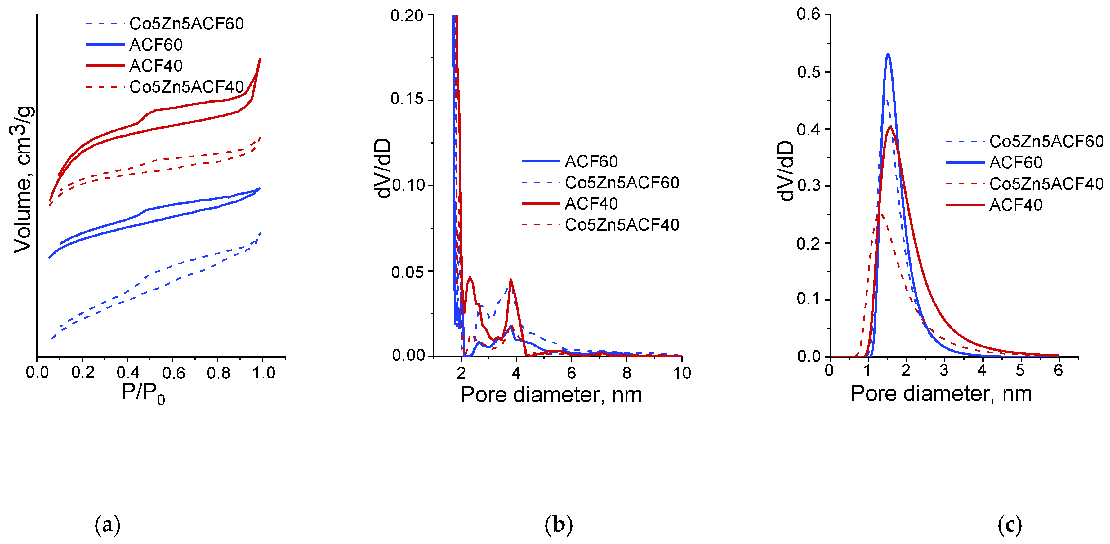
3.2.1. Texture and Surface Parameters

In Table 1 are presented data for the texture characteristics of carbon foams and KIT-6 silica modifications, elucidated by the low-temperature nitrogen physisorption. For the selected samples, the adsorption–desorption isotherms and pore size distribution are demonstrated in Figure 2 and Figure S2 (in Supplementary Materials). For the reference KIT-6 materials, no significant changes in the shape of the isotherms during the modification procedure were detected (Figure S2a). This indicates a preservation of the mesoporous texture of the silica support. The observed decrease in the BET surface area and pore volume (Table 1) and the changes in the pore size distribution (Figure S2b) evidence pore blocking due to the deposition of metal-containing species. For the ZnACF40 sample, the strong increase in the Vmic/Vmes ratio combined with a significant decrease in the BET surface area and pore volume (Figure 2b,c; Table 1) could be assigned to the predominant location of the metal particles into the mesopores of the carbon support. With the increase of Co content, the pore blocking effect became less-pronounced and a well-defined tendency for the Vmic/Vmes ratio decrease was observed (Table 1). This could be attributed to almost random deposition of finely dispersed particles in the whole porous matrix. More complicated were the textural variations for the ACF60-based modifications. Here, a significant change in the pore-size distribution combined with almost preservation in the BET surface area and pore volume were detected (Figure S2b,c; Table 1). Development of an additional porosity by the influence of the gaseous products, which released during the metal precursor decomposition, is assumed and this probably originates with the lower degree of ACF60 graphitization (Figure 1a). Besides, the deposition of metal particles on the external surface of the ACF60 support, which is promoted by its higher microporosity (Table 1) and well-developed surface functionality (Table 2, Figure 4), could not be fully excluded.
The FTIR spectra of the ACF60 modifications (Figure 4) exhibited a significant decrease in absorption in the 3200–3800 cm−1 region, with a simultaneous blue shifting of the bands at ca. 1724, 1400 and 1050 cm−1 as compared to the corresponding parent support. In agreement with the Boehm data (Table 2), this could be due to the interaction of the metal oxide species with surface hydroxyl, lactone, carbonyl and carboxyl groups. The observed change in the shape and position of the bands in the 1500–1600 cm−1 and 700–900 cm−1 regions supposes a change in the aromatic basal planes in ACF60 during the modification procedure, which is inconsistent with the nitrogen physisorption data (see above). Almost similar, but less pronounced features were detected for the ACF40 series of modifications, confirming the higher stability of the corresponding carbon support and the lower contribution of the surface acidic groups during the formation of the ferrite phase. The slight additional absorption features bellow 700 cm−1 in the spectra of all modifications could be attributed to M-O vibrations. The changes in the band at ca. 960 cm−1 for the KIT-6 supported materials (Figure S3, inset) indicates a strong interaction of the metal ions with the silica matrix [66].

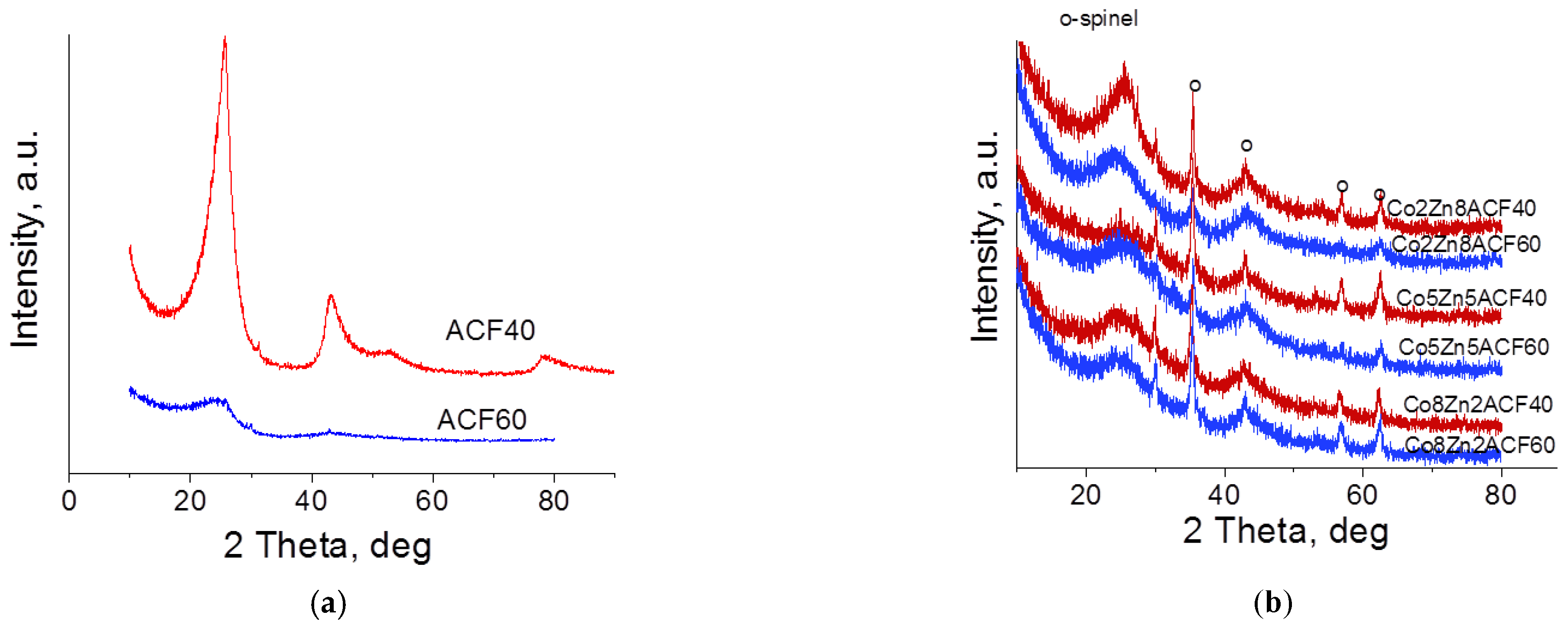
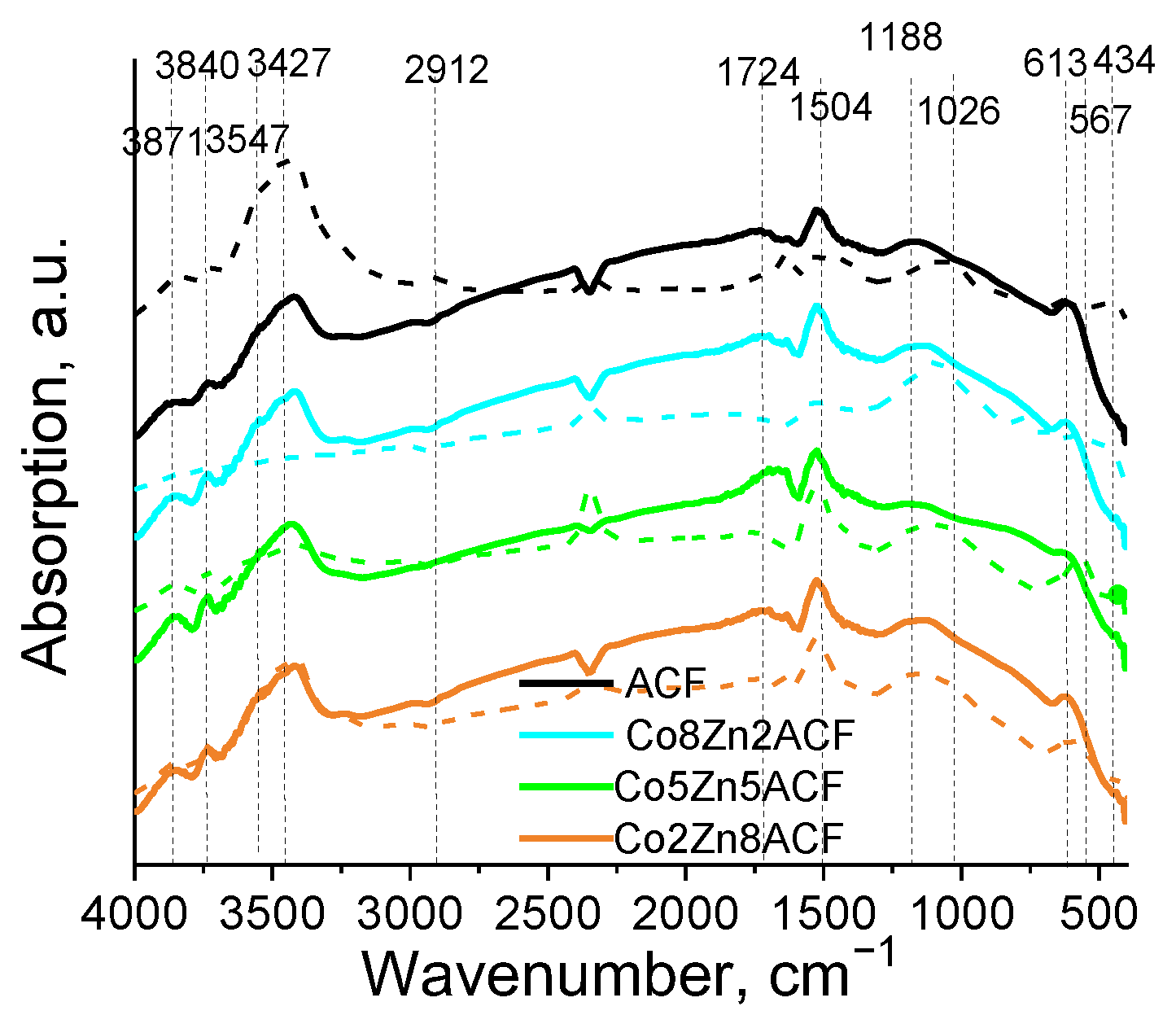
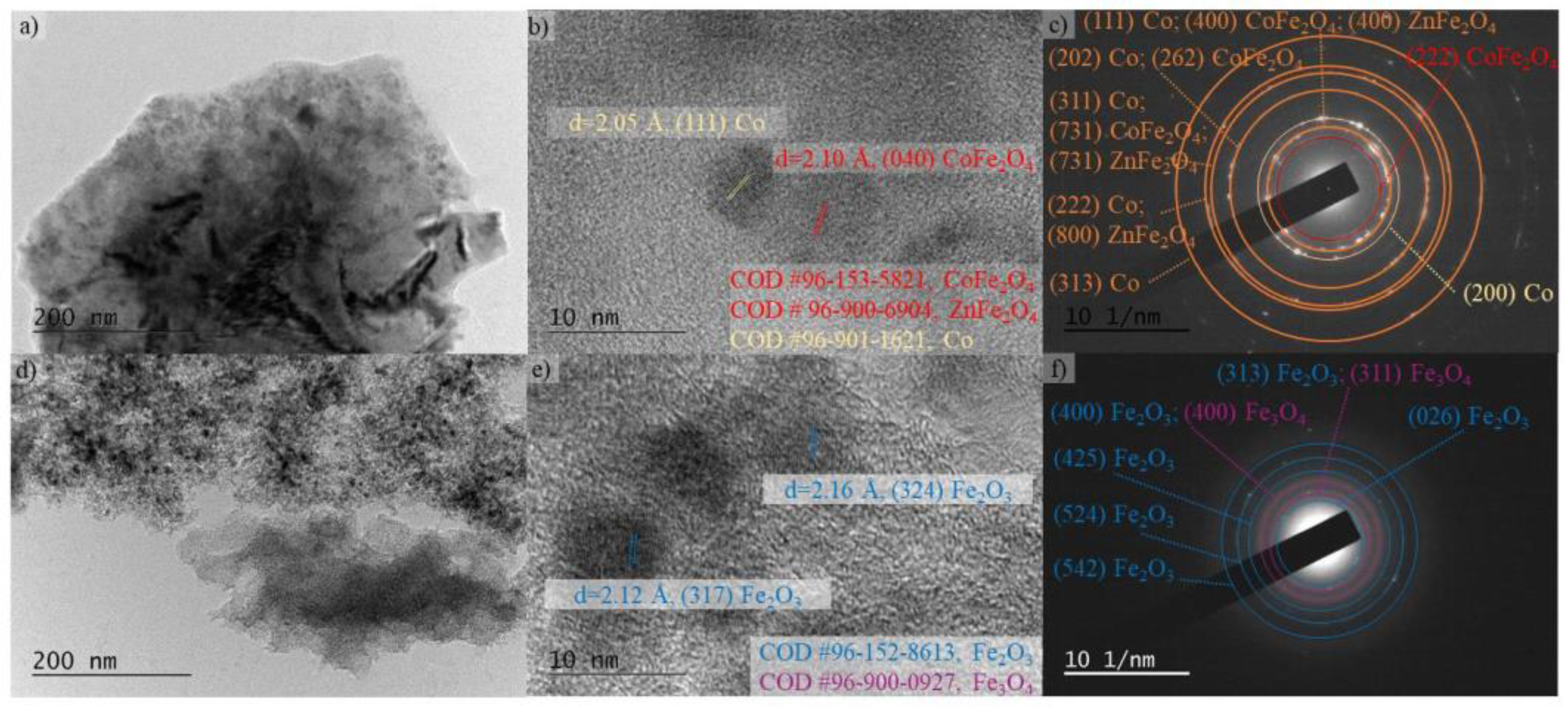
3.2.2. Structure, Morphology and Phase Composition

In Figure 1 and Figure S1 are shown XRD patterns of the carbon foam and silica-based modifications. Besides the reflections, typical of turbostratic carbon structure (See Section 3.2.1), well defined features at ca. 35.7°, 43.2°, 56.1° and 62.4° 2θ, corresponding to (311), (400), (511) and (440) planes of cubic spinel, were detected [65]. Data for the unit cell parameters and the average crystallite size of the spinel phase are collected in Table 1. Depending on the Co/Zn ratio, the average crystallite size of the ferrites varied between 22 and 26 nm for the ACF40 modifications and in a much wider range (8–43 nm) for their ACF60 analogues. With the increase of Co content in the spinels, the lattice parameters slightly decreased (Table 1, Figure S4). This is related to the smaller radius of the Co2+ ion (r = 0.82 Å) as compared to the Zn2+ one (r = 0.91 Å). Note that the change of the lattice parameters with the Co/Zn ratio did not obey Vegard’s low (Figure S4) [69], which was more pronounced for the ACF60 modifications. This proposes a higher degree of insertion of Co2+ ions in the spinel lattice or variations in the occupation of the sub-lattices [10,20,21,22]. Another explanation is the possible segregation of individual metal/metal oxide phases.
The low angle XRD patterns (Figure S1, inset) of the reference KIT-6 samples reveal the preservation of the pore ordering during the modification procedure. However, the observed decrease in the intensity of the main reflections, combined with their shifting to the wider 2θ, could be assigned to scattering from the inserting metal species silica walls, which was in accordance with the FTIR data (Figure S3, inset). No reflections of any metal oxide phase were observed in the wide angle region for most of the KIT-6 modifications, indicating its high dispersion (Figure S1). Only in the case of ZnKIT-6 and Co2Zn8KIT-6, were broad and low intensive reflections at ca. 33.2° and 35.5° 2θ, typical of hematite with average crystallite size of 10 nm, were detected.
For the visualization of the sample morphology, TEM images are obtained (Figure 5a,d). The metal-containing particles were observed as almost spherical dark spots with a higher electronic contrast compared to the lesser one of the surrounded carbon material. The homogeneous distribution of the particles in the carbon foam matrix is also observable. Generally, the particle size varied between 5 and 10 nm, but, inconsistent with the XRD data (Table 1), a small number of larger aggregates (above 20 nm) were also detected. In the HRTEM images (Figure 5b,e), the observed d-spacing of about 0.205 and 0.210 nm could be due to the (111) plane of Co (COD#96-901-1621) and (040) plane of CoFe2O4 (COD#96-153-5821), respectively. The formation of well-crystallized metal-containing particles in the carbon foam matrix was confirmed by Selected Area Electron Diffraction (SAED) analysis (Figure 5c,f). The diffraction rings revealed the presence of metallic Co, hematite (COD#96-152-8613), magnetite (COD#96-900-0927), CoFe2O4 and ZnFe2O4 (COD#96-900-6904). Due to the missing data in the database, the latter rings could be also attributed to mixed CoxZn1−xFe2O4 ferrites, which is in agreement with the XRD data.
Room temperature Mössbauer spectra were collected for more detail characterization of the iron-containing species (Figures S5–S7). The main Mössbauer parameters of isomer shift (δ), quadruple splitting (Δ), quadruple shift (2ε), hyperfine field (Beff) and full width of half-maxima (Γexp), as well as the relative part of each component (G), elucidated by the least squares fitting of a set of discrete Lorentzian line shapes, are listed in Table 3.
The spectra of all carbon foam modifications were well-fitted with several sextets and doublets. The sextet denoted as Sx1 possessed an isomer shift of about 0.30 mm/s, a zero quadruple shift and a hyperfine field of 48–49 T (Table 3). These parameters are attributable to Fe3+ ions in the tetrahedral environment [70]. The sextet Sx2 was with a higher isomer shift (δ = 0.50–0.60 mm·s−1) and lower hyperfine field (Beff = 44–46 T), which could be assigned to Fe2.5+ ions in the octahedral positions of a magnetite-like structure [70]. The deviation of the Mössbauer parameters from the reported ones for the pure magnetite [71] proposes changes in the environment of the iron ions due to the incorporation of Zn2+ and Co2+ ions. For both ZnACF samples, the Gtetra/Gocta was lower than the reported one for the magnetite [71], indicating that the Zn2+ ions predominantly occupy the tetrahedral sublattice. For the ACF40 series of materials, the Gtetra/Gocta ratio regularly decreased with the increase of the Co/Zn ratio up to 5:5 (sample Co5Zn5ACF40). This demonstrates a preferable insertion of the Co2+ ions in the tetrahedral positions. According to the XRD analysis (Table 1, Figure S4), this competitive substitution is probably accompanied with the segregation of a finely dispersed ZnO phase. The Gtetra/Gocta ratio increased with the further increase of the cobalt content in the samples, which was combined with a decrease in the isomer shift of the ions in the octahedral positions. This indicates a decrease in the number of Fe2+ ions in the octahedral sublattice, probably due to their replacement by Co2+ ions. The variations in the Mössbauer parameters with the Co/Zn ratio were more complex for the ACF60-based materials. In the case of CoACF60, additional small sextet components (Sx3), with parameters typical of hematite, appeared. This was in agreement with the SAED images (Figure 5).
The doublets in the spectra possessed parameters of Fe3+ ions (Figures S5 and S6, Table 3) and probably originate from the particles with a superparamagnetic behavior [72]. The higher quadruple splitting of the doublets than the reported ones for pure ZnFe2O4 (Δ = 0.4 mm·s−1) [73,74] proposes the existence of small (below 10–12 nm) and highly defective ferrite particles [72]. This assumption was in agreement with the HRTEM results (Figure 5). The doublets portion was larger for the ACF60-based analogues, which could be assigned to a higher dispersion of the iron containing its phase in it. In order to clarify the origin of the doublets, selected spectra at liquid nitrogen temperature (LNT) were recorded (Figure S6, Table 3). The observed decrease in the doublet part in the LNT spectrum as compared to the corresponding room temperature one evidences the presence of very small iron-containing particles (bellow 4 nm) with a supperparamagnetic behavior. The appearance of two sextets of iron ions in octahedral coordination (Table 3) indicates a different number of nearby neighbor iron ions from the tetrahedral sublattice [72].
The Mössbauer spectra of the reference Co8Zn2KIT-6 and Co5Zn5KIT-6 consisted only of doublets of Fe3+-containing particles with a superparamagnetic behavior (Table 3, Figure S7). In accordance with the XRD analyses (Figure S1), this could be attributed to their high dispersion. Contrary to the carbon foam-supported materials (Figures S5 and S6), the sextet components in the spectra of the other KIT-6 modifications possessed a quadruple split (2ε) of about −0.2 mm·s−1, which is typical of Fe3+ ions in the hematite structure. The lower hyperfine field of the sextets evidences that the hematite is partially substituted by Zn2+ and Co2+ ions (Table 3, Figure S7).

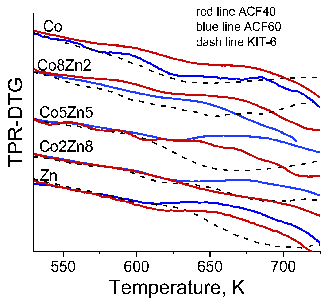
3.2.3. Temperature-Programmed Reduction-Thermo-Gravimetric Analyses (TPR-TG)

TPR-TG analyses were performed in order to highlight the influence of the supports on the redox properties of the metal oxide particles hosted in them (Figure 6). The broad reduction effect above 630 K for the reference ZnKIT-6 corresponded to about a 40% reduction in the transformation of Fe3+ to Fe0. Taking into account the XRD (Table 1) and Mössbauer (Table 3) data, it could be assigned to a partial step-wise reduction of Zn2+-substituted hematite to metallic iron.
For all cobalt-containing KIT-6 materials, a significant shift in the reduction effects to a lower temperature combined with higher weight loss were detected. With the increase of the Co/Fe ratio in the samples, these effects became more pronounced and clearly illustrate that the cobalt substitution promotes the labialization of the lattice oxygen ions in the hematite. Nevertheless, for all KIT-6-based materials, the reduction degrees were below 65%. In agreement with the FTIR (Figure S3) and nitrogen physisorption (Table 1) data, this could be due to the presence of small metal oxide species, which are either in strong interaction with the silica support, or are hardly acceptable due to their blocking in the long mesopores of the silica support. A common feature for the carbon foam-based modifications was the 80–100 K shifting of the reduction profiles to lower temperatures as compared to their silica analogues. In addition, the reduction degrees, calculated on the base of Co2+ and Fe3+ transitions to metals, were significantly higher and they generally varied between 70–100%. This evidences a facile impact of the carbon support on the reduction transformations of the loaded metal oxide particles. Taking into account the Mössbauer data (Table 3), the broad effect above 630 K for the ZnACF modifications could be assigned to the reduction transitions of Fe2+ and Fe3+ ions to Fe0. Similarly to the reference KIT-6 analogues, the Co- containing modifications of the carbon foams were easily reduced. “Spillover” of hydrogen, which was activated on the already reduced Co species, to the iron oxide particles could be proposed. The shape and position of the reduction profiles for different carbon-based materials evidence higher dispersion of the loaded phase on ACF60 (Figure 6), which is inconsistent with the XRD (Table 1) and Mössbauer (Table 3) analyses. In agreement with the Mössbauer (Table 3) and SAED (Figure 3) data, the additional low temperature effect at about 550–570 K, which was more pronounced for CoACF60, could be due to the segregation of individual hematite phase.

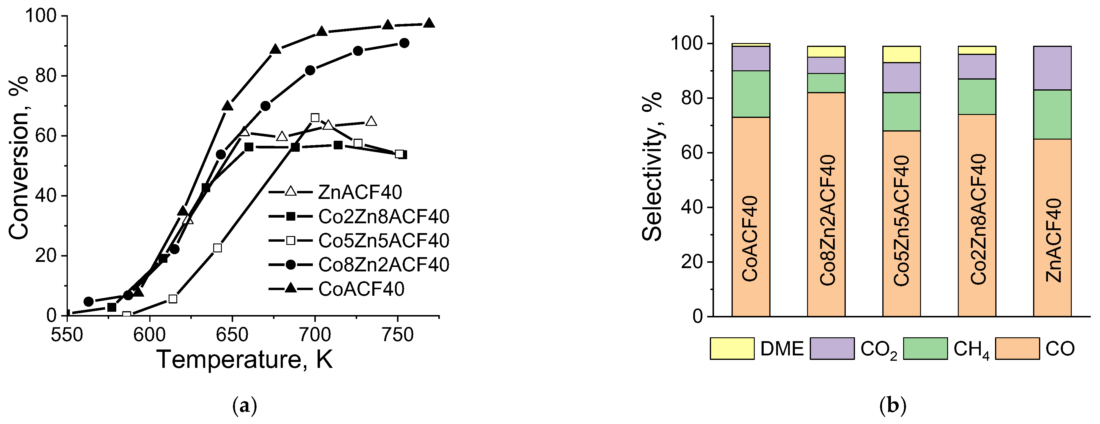
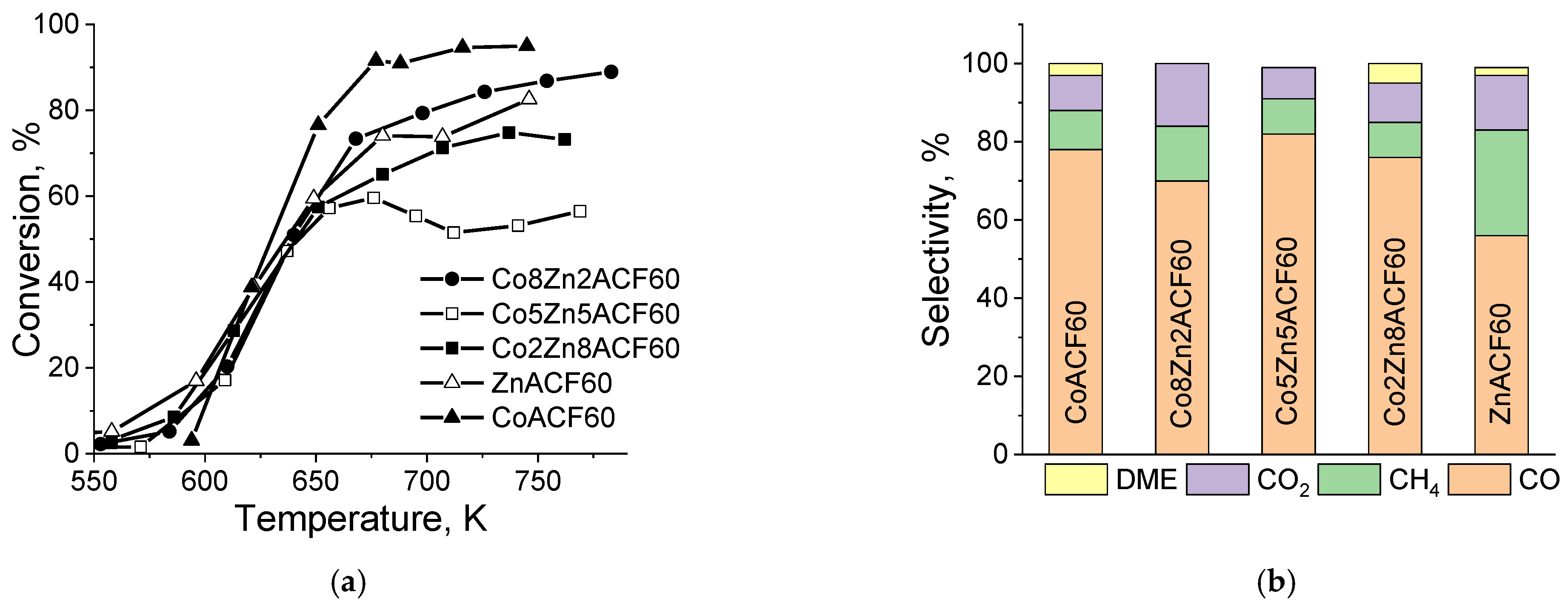
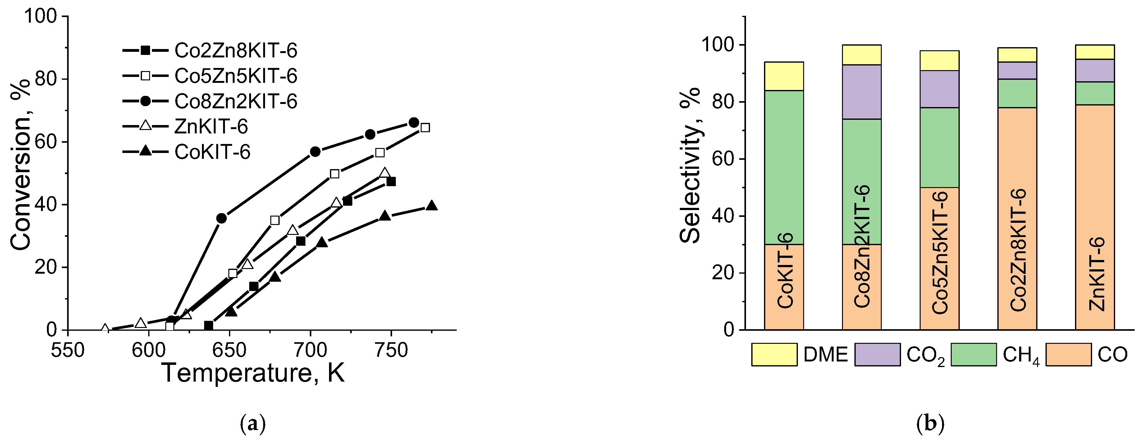
3.2.4. Catalytic Tests

In Figure 7 and Figure 8 the catalytic properties of CoxZn1−xFe2O4 modifications of carbon foams is demonstrated, derived from different precursors. For the proper understanding of the obtained results, the catalytic behavior of their KIT-6 silica analogues was also studied (Figure 9). For both CoACF samples (Figure 7 and Figure 8), the methanol decomposition was initiated at about 550 K and above 90% conversion was achieved with the temperature increase up to 670–690 K. The slightly steeper course of the conversion curve for CoACF60 indicates its higher catalytic activity. The main carbon-containing product was CO (about 70–75%), which illustrates the relatively high selectivity for hydrogen production during the methanol decomposition. CO2 (up to 10–15%), CH4 (bellow 10%) and in case of CoACF60, negligible amount of dimethyl ether (DME) were also detected as by-products.
For comparison, the reference CoKIT-6 (Figure 9) possessed catalytic activity just above 650 K and maximum conversion of 35% with above 55% selectivity to methane were registered. In accordance with the XRD (Table 1), TEM (Figure 5) and Mössbauer (Table 3) analyses, the higher catalytic activity in the selective decomposition of methanol to CO for the carbon foam-based materials originates from the formation of cobalt-substituted magnetite phase. The contribution of the Co2+-Co3+ and Fe2+-Fe3+ redox pairs, which occupied the more exposed octahedral positions in the spinel lattice (Table 3) could be assumed [16]. Small additives of Zn to the cobalt-containing spinels (samples Co8Zn2ACF) slightly decreased the catalytic activity in methanol decomposition to CO (Figure 7 and Figure 8). In accordance with the Mössbauer (Table 3) and TPR (Figure 6) data, this is probably related to the decrease of the number of the more active cobalt redox pairs. The catalytic behavior of the samples significantly changed with a further decrease in the Co/Zn ratio. For these series of samples, a lower catalytic activity and well-pronounced deactivation with the temperature increase above 650 K, were observed (Figure 7 and Figure 8). Taking into account the XRD (Figure S4), Mössbauer (Table 3) and TEM (Figure 5) analyses, this could be attributed to the preferable location of the smaller Co2+ ions in the tetrahedral spinel sub-lattice, which is accompanied with a segregation of less active phases, such as ZnO or Fe2O3 [30,31].
In accordance with the TPR study (Figure 6), the observed complex catalytic behavior of the samples and the absence of a clear relationship with their composition (Figure 7 and Figure 8) could be assigned to significant transformations of the spinel phase under the reduction reaction medium. Indeed, the Mössbauer analyses of the used in the catalytic test materials demonstrated disappearance of the sextets attributable to the substituted magnetite (Table 4, Figures S5 and S6). Instead, a new sextet component with an isomer shift of about 0.2 mm/s and a low hyperfine field, typical of Fe3C carbide, were detected [75,76]. With the increase in the Co/Zn ratio in the samples, an additional low-intensive sextet with parameters attributable to an α-(Fe,Co) alloy appeared. Note that the doublets in the spectra were almost preserved. To clarify the phase composition of the particles with a supper paramagnetic behavior, LNT Mössbauer spectra were recorded (Table 4, Figure S6). The observed simultaneous decrease in the relative part of the doublets and increase of the Fe3C and α-(Fe,Co) alloy sextets reveal that the reduction transformations under the reaction medium partially affects also the most finely dispersed spinel particles. However, the existence of a significant doublet component, even in the LNT spectra, indicates their stability most probably due to the strong interaction with the support and/or location in the less accessible micropores. This assumption is inconsistent with the data from the FTIR (Figure 3) and nitrogen physisorption (Table 1) study.
Conversely, all the supported KIT-6 silica-mixed Zn-Co composites demonstrated an improved catalytic activity and CO selectivity as compared to their single analogues (Figure 9). The catalytic activity regularly decreased with the increase in the Zn/Co ratio in the samples and a negligible change in the active phase during the catalytic test was detected by the Mössbauer analyses (Table 4). These results suggest a synergistic activity of Co2+ and Zn2+ ions, which were stabilized in the hematite structure.
Therefore, the diverse morphology and phase composition of the samples with similar Co/Zn ratios, as well as the variations in their reduction and catalytic properties, clearly demonstrate the strong effect of the supports on the formation of the CoxZn1−xFe2O4 ferrite structures.
During the heating in the inert atmosphere, decomposition of the impregnated within the support metal nitrate precursors to CoO, Fe2O3 and ZnO could be proposed as the initial step of the modification procedure. Obviously, due to the reduction ability of the carbon foam matrix, the hematite particles easily transform to magnetite. The next step of solid-state interaction between the metal oxides provides the formation of Zn- and Co-substituted magnetite [77,78]. XRD (Table 1, Figure S4) and Mössbauer (Table 3) analyses demonstrated the higher ability of Co2+ incorporation in the magnetite lattice. Moreover, predominantly, the occupation of the tetrahedral positions in the spinel structure by Co2+ ions at a low Co/Zn ratio and their preferable location on the octahedral sites with the increase of Co content in the samples (Table 3) was observed. Obviously, the surface functionality (Table 2), the texture characteristics (Table 1) and the reduction ability (Figure 6) of the carbon foam matrix could control the phase composition, the dispersion and the location of the individual metal oxides in the porous host matrix. This regulates the intimate contact and the interaction between them and, together with the reaction medium, regulates in a complex way the phase composition of the catalytic active phase. Thus, the higher catalytic activity of the ACF60-based modifications (Figure 8) could be related to the superimposition of several effects originated from the following:
  • Higher dispersion of the loaded metal oxide phase (Table 3), which was promoted by the higher amount of surface functional groups (Table 2) and a significant portion of micropores in the support (Table 1);
  • Higher degrees of insertion of the Co2+ ions in the spinels (Figure S4) due to the improved contact between the individual metal oxide species;
  • Higher accessibility of the active particles in the porous matrix due to the development of additional porosity (Table 1) during the modification procedure.
All these features could be simply achieved using a carbon foam precursor with a higher furfural/coal tar pitch ratio.
The impact of the carbon foam support on the formation of the spinel phase is confirmed by the diverse phase composition of the KIT-6 silica modifications, where only Co2+- and Zn2+- substituted hematite is observed (Table 3). Lower accessibility of the active particles, predominantly located in the long mesopores of the silica matrix (Table 1), could be proposed. All this ensures a significantly lower catalytic activity (Figure 7, Figure 8 and Figure 9) and less pronounced transformations under the reaction medium (Table 4) of the KIT-6 based modifications as compared to their carbon foam analogues.

4. Conclusions

Nano-sized cobalt-zinc substituted-magnetite with different compositions was produced by incipient wetness impregnation of carbon foam, obtained from a waste precursor (coal tar pitch and furfural) with a methanol solution of the corresponding nitrates and their further decomposition in nitrogen atmosphere. The phase composition, the morphology and the distribution of the metal ions in the spinel sub-lattices and the related redox and catalytic properties depend on the texture and surface functionality of the carbon foam support. They could be easily tuned by a variation of the composition of the carbon foam precursor and by the Co/Zn ratio of the impregnated solution. The high furfural/coal tar pitch ratio provides the formation of a higher amount of micropores and surface acidic functional groups in the carbon foam as well as in the development of additional porosity during the modification procedure. This ensures a higher catalytic activity due to the improved dispersion of the loaded metal oxide phase, higher degrees of insertion of Co2+ ions in the binary spinels and better accessibility of the active species to the reactants. The comparison with the reference mesoporous silica-based analogues demonstrates the potential of the supported carbon foam cobalt-zinc ferrites as catalysts in the selective decomposition of methanol to syngas.

Supplementary Materials

The following are available online at https://www.mdpi.com/article/10.3390/sym13081532/s1, Figure S1: XRD patterns of selected KIT-6 modifications. Inset: low angle XRD patterns, Figure S2: Nitrogen physisorption isotherms (shifted by y-axis) (a) and pore size distribution (b) for pristine and modified mesoporous KIT-6 silica, Figure S3: FTIR spectra of parent and modified mesoporous KIT-6 silica, Figure S4: Changes in the unit cell parameters of spinel phase for the ACF40 and ACF60 modified carbon foams, Figure S5: Room temperature Mössbauer spectra of ACF60 supported samples before (left) and after (cat) the catalytic test (right) and selected Mössbauer spectra at liquid nitrogen temperature (LNT), Figure S6: Room temperature Mössbauer spectra of the initial ACF40 based materials and selected spectra after the catalytic test (cat), Figure S7: Room temperature Mössbauer spectra of the initial KIT-6 based materials and selected spectra after the catalytic test (cat).

Author Contributions

Conceptualization, T.T.; methodology, T.T. and N.P.; investigation, R.I., D.K. (Daniela Karashanova), D.K. (Daniela Kovacheva), N.V., N.P. and I.S.; writing—original draft preparation, T.T.; writing—review and Editing, R.I., D.K. (Daniela Karashanova), D.K. (Daniela Kovacheva), N.V., N.P. and I.S.; Visualization, T.T., R.I., D.K. (Daniela Karashanova), D.K. (Daniela Kovacheva), N.V., N.P. and I.S.; supervision, T.T.; project administration, T.T.; funding acquisition, T.T. All authors have read and agreed to the published version of the manuscript.

Funding

This research was funded by Bulgarian Scientific Fund: Project KP-06-H 29/2 and Project BG05M2OP001-1.002-0019: “Clean technologies for sustainable environment—water, waste, energy for circular economy” (Clean & Circle).

Institutional Review Board Statement

Not applicable.

Informed Consent Statement

Not applicable.

Data Availability Statement

Not applicable.

Acknowledgments

Research equipment of distributed research infrastructure INFRAMAT (part of Bulgarian National roadmap for research infrastructures) supported by Bulgarian Ministry of Education and Science was used in this investigation.

Conflicts of Interest

The authors declare no conflict of interest.

References

  1. Roco, M.C. The emergence and policy implications of converging new technologies integrated from the nanoscale. J. Nanopart. Res. 2005, 7, 129–143. [Google Scholar] [CrossRef]
  2. Khalil, M.; Jan, B.M.; Tong, C.W.; Berawi, M.A. Advanced nanomaterials in oil and gas industry: Design, application and challenges. Appl. Energy 2017, 191, 287–310. [Google Scholar] [CrossRef]
  3. Lehner, R.; Wang, X.; Marsch, S.; Hunziker, P. Intelligent nanomaterials for medicine: Carrier platforms and targeting strategies in the context of clinical application. Nanomed. Nanotechnol. Biol. Med. 2013, 9, 742–757. [Google Scholar] [CrossRef]
  4. Keçili, R.; Büyüktiryaki, S.; Mustansar, C. Advancement in bioanalytical science through nanotechnology: Past, present and future. Trends Anal. Chem. 2019, 110, 259–276. [Google Scholar] [CrossRef]
  5. Kaur, A.; Bhargava, G.K. Review paper on nickel-zinc nano ferrite. Mater. Today Proc. 2021, 37, 3082–3086. [Google Scholar] [CrossRef]
  6. Masunga, N.; Mmelesi, O.K.; Kefeni, K.K.; Mamba, B.B. Recent advances in copper ferrite nanoparticles and nanocomposites synthesis, magnetic properties and application in water treatment: Review. J. Environ. Chem. Eng. 2019, 7, 103179. [Google Scholar] [CrossRef]
  7. Kharisov, B.I.; Dias, H.V.R.; Kharissova, O.V. Mini-review: Ferrite nanoparticles in the catalysis. Arab. J. Chem. 2019, 12, 1234–1246. [Google Scholar] [CrossRef] [Green Version]
  8. Mmelesi, O.K.; Masunga, N.; Kuvarega, A.; Nkambule, T.T.; Mamba, B.B.; Kefeni, K.K. Cobalt ferrite nanoparticles and nanocomposites: Photocatalytic, antimicrobial activity and toxicity in water treatment. Mater. Sci. Semicond. Process. 2021, 123, 105523. [Google Scholar] [CrossRef]
  9. Omelyanchik, A.; Levada, K.; Pshenichnikov, S.; Abdolrahim, M.; Baricic, M.; Kapitunova, A.; Galieva, A.; Sukhikh, S.; Astakhova, L.; Antipov, S.; et al. Green Synthesis of Co-Zn Spinel Ferrite, Nanoparticles: Magnetic and Intrinsic Antimicrobial Properties. Materials 2020, 13, 5014. [Google Scholar] [CrossRef]
  10. Ceicilia, A.S.J.; Dinesh, A.; Nirmala, G.F.; Preetha, A.C.; Slimani, Y.; Almessiere, M.A.; Baykal, A.; Xavier, B.; Vinosha, P.A.; Manikandan, A. Review on recent advances of zinc substituted cobalt ferrite nanoparticles: Synthesis characterization and diverse applications. Ceram. Int. 2021, 47, 10512–10535. [Google Scholar]
  11. Tatarchuk, T.R.; Paliychuk, N.D.; Bououdina, M.; Al-Najar, B.; Pacia, M.; Macyk, W.; Shyichuk, A. Effect of cobalt substitution on structural, elastic, magnetic and optical properties of zinc ferrite nanoparticles. J. Alloys Compd. 2018, 731, 1256–1266. [Google Scholar] [CrossRef]
  12. Narang, S.B.; Pubby, K. Nickel Spinel Ferrites: A review. J. Magn. Magn. Mater. 2021, 519, 167163. [Google Scholar] [CrossRef]
  13. Parveen, S.; Premkumar, T.; Poornima, S.; Govindarajan, S. Catalytic activity of nanocrystalline ZnM2O4 (M = Fe, Co) prepared via simple and facile synthesis of thermal decomposition of mixed metal complexes of Schiff bases generated from a-ketobutyric acid and diaminoguanidine. J. Saudi Chem. Soc. 2019, 23, 691–701. [Google Scholar] [CrossRef]
  14. Chahar, D.; Taneja, S.; Bisht, S.; Kesarwani, S.; Thakur, P.; Thakur, A.; Sharma, P.B. Photocatalytic activity of cobalt substituted zinc ferrite for the degradation of methylene blue dye under visible light irradiation. J. Alloys Compd. 2021, 851, 156878. [Google Scholar] [CrossRef]
  15. Huang, Y.H.; Wang, S.F.; Tsai, A.P.; Kameoka, S. Catalysts prepared from copper-nickel ferrites for the steam reforming of methanol. J. Power Sources 2015, 281, 138–145. [Google Scholar] [CrossRef]
  16. Peng, Y.; Tang, H.; Yao, B.; Gao, X.; Yang, X.; Zhou, Y. Activation of peroxymonosulfate (PMS) by spinel ferrite and their composites in degradation of organic pollutants: A Review. Chem. Eng. J. 2021, 414, 128800. [Google Scholar] [CrossRef]
  17. Nlebedim, I.C.; Snyder, J.E.; Moses, A.J.; Jiles, D.C. Dependence of the magnetic and magnetoelastic properties of cobalt ferrite on processing parameters. J. Magn. Magn. Mater. 2010, 322, 3938–3942. [Google Scholar] [CrossRef]
  18. Muhammad, A.; Sato-Turtelli, R.; Kriegisch, M.; Grössinger, R.; Kubel, F.; Konegger, T. Large enhancement of magnetostriction due to compaction hydrostatic pressure and magnetic annealing in CoFe2O4. J. Appl. Phys. 2012, 111, 013918. [Google Scholar] [CrossRef]
  19. Atif, M.; Asghar, M.W.; Nadeem, M.; Khalid, W.; Ali, Z.; Badshah, S. Synthesis and investigation of structural, magnetic and dielectric properties of zinc substituted cobalt ferrites. J. Phys. Chem. Solids 2018, 123, 36–42. [Google Scholar] [CrossRef]
  20. Tatarchuk, T.; Shyichuk, A.; Sojka, Z.; Gryboś, J.; Naushad, M.; Kotsyubynsky, V.; Kowalska, M.; Kwiatkowska-Marks, S.; Danyliuk, N. Green synthesis, structure, cations distribution and bonding characteristics of superparamagnetic cobalt-zinc ferrites nanoparticles for Pb(II) adsorption and magnetic hyperthermia applications. J. Mol. Liquids 2021, 328, 115375. [Google Scholar] [CrossRef]
  21. Naik, M.M.; Naik, H.S.B.; Nagaraju, G.; Vinuth, M.; Vinu, K.; Viswanath, R. Green synthesis of zinc doped cobalt ferrite nanoparticles: Structural, optical, photocatalytic and antibacterial studies. Nano Struct. Nano Objects 2019, 19, 100322. [Google Scholar] [CrossRef]
  22. Andhare, D.D.; Patade, S.R.; Kounsalye, J.S.; Jadhav, K.M. Effect of Zn doping on structural, magnetic and optical properties of cobalt ferrite nanoparticles synthesized via. Co-precipitation method. Phys. B 2020, 583, 412051. [Google Scholar] [CrossRef]
  23. Rao, P.A.; Rao, K.S.; Raju, T.R.K.; Kapusetti, P.G.; Choppadandi, M.; Varma, M.C.; Rao, K.H. A systematic study of cobalt-zinc ferrite nanoparticles for selfregulated magnetic hyperthermia. J. Alloys Compd. 2019, 794, 60–67. [Google Scholar]
  24. Hill, J.M. Sustainable and/or waste sources for catalysts: Porous carbon development and gasification. Catal. Today 2017, 285, 204–210. [Google Scholar] [CrossRef]
  25. García, P.G. Activated carbon from lignocellulosics precursors: A review of the synthesis methods, characterization techniques and applications. Renew. Sustain. Energy Rev. 2018, 82, 1393–1414. [Google Scholar] [CrossRef]
  26. Danish, M.; Ahmad, T. A review on utilization of wood biomass as a sustainable precursor for activated carbon production and application. Renew. Sustain. Energy Rev. 2018, 87, 1–21. [Google Scholar] [CrossRef]
  27. Bader, N.; Ouederni, A. Functionalized and metal-doped biomass-derived activated carbons for energy storage application. J. Energy Storage 2017, 13, 268–276. [Google Scholar] [CrossRef]
  28. Menya, E.; Olupot, P.W.; Storz, H.; Lubwama, M.; Kiros, Y. Production and performance of activated carbon from rice husks for removal of natural organic matter from water: A review. Chem. Eng. Res. Des. 2018, 129, 271–296. [Google Scholar] [CrossRef]
  29. Tsoncheva, T.; Mileva, A.; Tsyntsarski, B.; Paneva, D.; Spassova, I.; Kovacheva, D.; Velinov, N.; Karashanova, D.; Georgieva, B.; Petrov, N. Activated carbon from Bulgarian peach stones as a support of catalysts for methanol decomposition. Biomass Bioenergy 2018, 109, 135–146. [Google Scholar] [CrossRef]
  30. Tsoncheva, T.; Mileva, A.; Paneva, D.; Kovacheva, D.; Spassova, I.; Nihtianova, D.; Markov, P.; Petrov, N.; Mitov, I. Zinc ferrites hosted in activated carbon from waste precursors as catalysts in methanol decomposition. Microporous and Mesoporous Mater. 2016, 229, 59–67. [Google Scholar] [CrossRef]
  31. Tsoncheva, T.; Mileva, A.; Marinov, S.P.; Paneva, D.; Velinov, N.; Spassova, I.; Kosateva, A.; Kovacheva, D.; Petrov, N. Activated carbons from used motor oil as catalyst support for sustainable environmental protection. Microporous and Mesoporous Mater. 2018, 259, 9–16. [Google Scholar] [CrossRef]
  32. Tsoncheva, T.; Tsyntsarski, B.; Ivanova, R.; Spassova, I.; Kovacheva, D.; Issa, G.; Paneva, D.; Karashanova, D.; Dimitrov, M.; Georgieva, B.; et al. NixZn1-xFe2O4 modified activated carbons from industrial waste as catalysts for hydrogen production. Microporous and Mesoporous Mater. 2019, 285, 96–104. [Google Scholar] [CrossRef]
  33. Zeng, Z.; Zhang, Y.; Ma, X.D.; Shahabadi, S.I.S.; Che, B.; Wang, P.; Lu, X. Biomass-based honeycomb-like architectures for preparation of robust carbon foams with high electromagnetic interference shielding performance. Carbon 2018, 140, 227–236. [Google Scholar] [CrossRef]
  34. Rao, G.S.; Nabipour, H.; Zhang, P.; Wang, X.; Xing, W.; Song, L.; Hu, Y. Lightweight, hydrophobic and recyclable carbon foam derived from lignin–resorcinol–glyoxal resin for oil and solvent spill capture. J. Mater. Technol. 2020, 9, 4655–4664. [Google Scholar] [CrossRef]
  35. Min, Z.H.; Cao, M.; Zhang, S.; Wang, X.D.; Yong, Y.G. Effect of precursor on the pore structure of carbon foams. New Carbon Mater. 2007, 22, 75–79. [Google Scholar] [CrossRef]
  36. Li, Y.; Shen, B.; Pei, X.; Zhang, Y.; Yi, D.; Zhai, W.; Zhang, L.; Wei, X.; Zheng, W. Ultrathin carbon foams for effective electromagnetic interference shielding. Carbon 2016, 100, 375–385. [Google Scholar] [CrossRef]
  37. Banerjee, C.; Chandaliya, V.K.; Dash, P.S.; Meikap, B.C. Effect of different parameters on porosity and compressive strength of coal tar pitch derived carbon foam. Diam. Relat. Mater. 2019, 95, 83–90. [Google Scholar] [CrossRef]
  38. Xing, B.; Zeng, H.; Huang, G.; Jia, J.; Yuan, R.; Zhang, C.; Sun, Q.; Cao, Y.; Chen, Z.; Liu, B. Magnesium citrate induced growth of noodle-like porous graphitic carbons from coal tar pitch for high-performance lithium-ion batteries. Electrochim. Acta 2021, 376, 138043. [Google Scholar] [CrossRef]
  39. Klett, J.W. The role of precursor modification on the production of graphite foam. Carbon 2019, 144, 43–54. [Google Scholar] [CrossRef]
  40. Inagaki, M.; Qiu, J.; Guo, Q. Carbon foam: Preparation and application. Carbon 2015, 87, 128–152. [Google Scholar] [CrossRef]
  41. Tsyntsarski, B.; Petrova, B.; Budinova, T.; Petrov, N.; Krzesinska, M.; Pusz, S.; Majewska, J.; Tzvetkov, P. Carbon foam derived from pitches modified with mineral acids by a low pressure foaming process. Carbon 2010, 48, 3523–3530. [Google Scholar] [CrossRef]
  42. Gao, F.; Zang, Y.H.; Wang, Y.; Guan, C.Q.; Qu, J.Y.; Wu, M.B. A review of the synthesis of carbon materials for energy storage from biomass and coal/heavy oil waste. New Carbon Mater. 2021, 36, 34–48. [Google Scholar] [CrossRef]
  43. Wu, X.; Li, S.; Wang, B.; Liu, J.; Yu, M. Mesoporous Ni-Co based nanowire arrays supported on three-dimensional N-doped carbon foams as non-noble catalysts for efficient oxygen reduction reaction. Microporous and Mesoporous Mater. 2016, 231, 128–137. [Google Scholar] [CrossRef]
  44. Stoycheva, I.; Tsyntsarski, B.; Vasileva, M.; Petrova, B.; Georgiev, G.; Budinova, T.; Szeluga, U.; Pusz, S.; Kosateva, A.; Petrov, N. New method for synthesis of carbon foam on the base of mixture of coal tar pitch and furfural without using pressure and stabilization treatment. Diam. Relat. Mater. 2020, 109, 108066. [Google Scholar] [CrossRef]
  45. Liu, H.; Wu, J.; Zhuang, Q.; Dang, A.; Li, T.; Zhao, T. Preparation and the electromagnetic interference shielding in theX-band of carbon foams with Ni-Zn ferrite additive. J. Eur. Ceram. Soc. 2016, 36, 3939–3946. [Google Scholar] [CrossRef]
  46. Qin, G.X.; Hao, Y.; Wang, S.; Dong, Y.B. Rapid formation of nitrogen-doped carbon foams by self-foaming as metal free catalysts for selective oxidation of aromatic alkanes. Appl. Catal. A Gen. 2020, 591, 117400. [Google Scholar] [CrossRef]
  47. Velasco, L.F.; Tsyntsarski, B.; Petrova, B.; Budinova, T.; Petrov, N.; Parra, J.B.; Ania, C.O. Carbon foams as catalyst supports for phenol photodegradation. J. Hazard. Mater. 2010, 184, 843–848. [Google Scholar] [CrossRef] [PubMed] [Green Version]
  48. Varila, T.; Makela, E.; Kupila, R.; Romar, H.; Hu, T.; Karinen, R.; Puurunen, R.L.; Lassi, U. Conversion of furfural to 2-methylfuran over CuNi catalysts supported on biobased carbon foams. Catal. Today 2021, 367, 16–27. [Google Scholar] [CrossRef]
  49. Avgouropoulos, G.; Papavasiliou, J.; Ioannides, T. Hydrogen production from methanol over combustion-synthesized noble metal/ceria catalysts. Chem. Eng. J. 2009, 154, 274–280. [Google Scholar] [CrossRef]
  50. Li, G.; Gu, C.; Zhu, W.; Wang, X.; Yuan, X.; Cui, Z.; Wang, H.; Gao, Z. Hydrogen production from methanol decomposition using Cu-Al spinel catalysts. J. Clean. Prod. 2018, 183, 415–423. [Google Scholar] [CrossRef]
  51. Bai, Z.; Liu, T.; Liu, Q.; Lei, J.; Gong, L.; Jin, H. Performance investigation of a new cooling, heating and power system with methanol decomposition based chemical recuperation process. Appl. Energy 2018, 229, 1152–1163. [Google Scholar] [CrossRef]
  52. Pham, T.L.M.; Vo, D.V.N.; Nguyen, H.N.T.; Pham-Tran, N.N. C-H versus O-H bond scission in methanol decomposition on Pt (111): Role of the dispersion interaction. Appl. Surf. Sci. 2019, 481, 1327–1334. [Google Scholar] [CrossRef]
  53. Jing, J.; Li, L.; Chu, W.; Wei, Y.; Jiang, C. Microwave-assisted synthesis of high performance copper-based catalysts for hydrogen production from methanol decomposition. Int. J. Hydrog. Energy 2018, 43, 12059–12068. [Google Scholar] [CrossRef]
  54. Fan, M.; Xu, Y.; Sakurai, J.; Demura, M.; Hirano, T.; Teraoka, Y.; Yoshigoe, A. Spontaneous activation behavior of Ni3Sn, an intermetallic catalyst, for hydrogen production via methanol decomposition. Int. J. Hydrog. Energy 2015, 40, 12663–12673. [Google Scholar] [CrossRef]
  55. Tsyntsarski, B.; Petrova, B.; Budinova, T.; Petrov, N.; Velasco, L.F.; Parra, J.B.; Ania, C.O. Porosity development during steam activation of carbon foams from chemically modified pitch. Microporous and Mesoporous Mater. 2012, 154, 56–61. [Google Scholar] [CrossRef] [Green Version]
  56. Kleitz, F.; Choi, S.H.; Ryoo, R. Cubic Ia3d large mesoporous silica: Synthesis and replication to platinum nanowires, carbon nanorods and carbon nanotubes. Chem. Commun. 2003, 17, 2136–2137. [Google Scholar] [CrossRef] [PubMed]
  57. Bruker AXS. TOPAS V4: General Profile and Structure Analysis Software for Powder Diffraction Data—User’s Manual; Bruker AXS: Karlsruhe, Germany, 2008. [Google Scholar]
  58. Boehm, H.P. Advances in Catalysis; Eley, D.D., Pines, H., Weisz, P.B., Eds.; Academic Press: New York, NY, USA, 1966; Volume 16, pp. 179–274. [Google Scholar]
  59. Papirer, E.; Li, S.; Donnet, J.B. Contribution to the study of basic surface groups on carbons. Carbon 1987, 25, 243–247. [Google Scholar] [CrossRef]
  60. Yu, M.; Li, C.; Ao, X.; Chen, Q. Fabrication of coal tar pitch–derived reticulated carbon foam as oxidation resistant thermal insulation. J. Anal. Appl. Pyrolysis 2019, 141, 104643. [Google Scholar] [CrossRef]
  61. Inagaki, M.; Kang, F. Materials Science and Engineering of Carbon: Fundamentals; Butterworth-Heinemann: Oxford, UK, 2014. [Google Scholar]
  62. Liu, H.; Song, H.; Hou, W.; Chang, Y.; Zhang, Y.; Li, Y.; Zhao, Y.; Han, G. Coal tar pitch-based hierarchical porous carbons prepared in molten salt for supercapacitors. Mater. Chem. Phys. 2021, 265, 124491. [Google Scholar] [CrossRef]
  63. Zhuang, Q.Q.; Cao, J.P.; Zhao, X.Y.; Wu, Y.; Zhou, Z.; Zhao, M.; Zhao, Y.P.; Wei, X.Y. Preparation of layered-porous carbon from coal tar pitch narrow fractions by single-solvent extraction for superior cycling stability electric double layer capacitor application. J. Colloid Interface Sci. 2020, 567, 347–356. [Google Scholar] [CrossRef]
  64. Wu, J.; Wang, J.; Guan, T.; Zhang, G.; Wang, N.; Li, K. Tailored C-N bond toward defect-rich hierarchically porous carbon from coal tar pitch for high-efficiency adsorptive desulfurization. Fuel 2021, 292, 120251. [Google Scholar] [CrossRef]
  65. Karthikeyan, P.; Sirajudheen, P.; Nikitha, M.R.; Meenakshi, S. Removal of phosphate and nitrate via a zinc ferrite-activated carbon hybrid composite under batch experiments: Study of isotherm and kinetic equilibriums. Environ. Nanotechnol. Monit. Manag. 2020, 14, 100378. [Google Scholar] [CrossRef]
  66. Yuan, L.Y.; Bai, Z.Q.; Zhao, R.; Liu, Y.L.; Li, Z.J.; Chu, S.Q.; Zheng, L.R.; Zhang, J.; Zhao, Y.L.; Chai, Z.F.; et al. Introduction of bifunctional groups into mesoporous silica for enhancing uptake of Thorium(IV) from aqueous solution. ACS Appl. Mater. Interfaces 2014, 6–7, 4786–4796. [Google Scholar] [CrossRef] [PubMed]
  67. Fernandes, F.R.D.; Pinto, F.G.H.S.; Lima, E.L.F.; Souza, L.D.; Caldeira, V.P.S.; Santos, A.G.D. Influence of synthesis parameters in obtaining KIT-6 mesoporous material. Appl. Sci. 2018, 8, 725. [Google Scholar] [CrossRef] [Green Version]
  68. Wang, X. Stepwise removal of the copolymer template from mesopores and micropores in SBA-15. J. Porous Mater. 2011, 18, 623–630. [Google Scholar] [CrossRef]
  69. Sundararajan, M.; Kennedy, L.J.; Aruldoss, U.; Pash, S.K.; Vijay, J.J.; Dunn, S. Microwave combustion synthesis of zinc substituted nanocrystalline spinel cobalt ferrite: Structural and magnetic studies. Mater. Sci. Semicond. Process. 2015, 40, 1–10. [Google Scholar] [CrossRef]
  70. Greenwood, N.; Gibb, T. Mössbauer Spectroscopy; Capman and Hall Ltd.: London, UK, 1971. [Google Scholar]
  71. Shipilin, M.A.; Zakharova, I.N.; Shipilin, A.M.; Bachurin, V.I. Mössbauer studies of magnetite nanoparticles. J. Synch. Investig. 2014, 8, 557–561. [Google Scholar] [CrossRef]
  72. Kopcewicz, M.; Grabias, A.; Kuryliszyn-Kudelska, I.; Dobrowolski, W. Mössbauer effect study of superparamagnetic behavior of ZnFe2O4 nanoparticles formed in ZnO doped with Fe2O3. Phys. Status Solidi B 2019, 256, 1800223. [Google Scholar] [CrossRef]
  73. Koleva, K.; Velinov, N.; Tsoncheva, T.; Mitov, I.; Kunev, B. Preparation, structure and catalytic properties of ZnFe2O4. Bulg. Chem. Commun. 2013, 45, 434–439. [Google Scholar]
  74. Koleva, K.; Velinov, N.; Tsoncheva, T.; Mitov, I. Mössbauer study of Cu1-xZnxFe2O4 catalytic materials. Hyperfine Interact. 2014, 226, 89–97. [Google Scholar] [CrossRef]
  75. Herranz, T.; Rojas, S.; Pérez-Alonso, F.J.; Ojeda, M.; Terreros, P.; Fierro, J.L.G. Genesis of iron carbides and their role in the synthesis of hydrocarbons from synthesis gas. J. Catal. 2006, 243, 199–211. [Google Scholar] [CrossRef]
  76. Scrimshire, A.; Lobera, A.L.; Kultyshev, R.; Ellis, P.; Forder, S.D.; Bingham, P.A. Variable Temperature 57Fe-Mössbauer Spectroscopy Study of Nanoparticle Iron Carbides. Croat. Chem. Acta 2015, 88, 531–537. [Google Scholar] [CrossRef]
  77. Roy, P.C.; Doh, W.H.; Jo, S.K.; Kim, C.M. Interaction of methanol and hydrogen on a ZnO (0001) single crystal surface. J. Phys. Chem. C 2013, 117, 15116–15121. [Google Scholar] [CrossRef]
  78. Pankov, V.V.; Bashkirov, L.A. Mechanism of Ni-Zn ferrite formation. J. Solid State Chem. 1981, 39, 298–308. [Google Scholar] [CrossRef]
Figure 1. XRD patterns of the pristine ACF40 and ACF60 supports (a) and CoxZn1−xFe2O4-modified ACF40 and ACF60 (b).
Symmetry 13 01532 g001
Figure 2. Nitrogen physisorption isotherms (shifted by y-axis) (a), pore size distribution (b) and micropore size distribution (c) for parent ACF supports and selected CoxZn1−xFe2O4 modifications.
Symmetry 13 01532 g002
Figure 3. SEM images of parent ACF40 before (a) and after (b) the activation with water vapor.
Symmetry 13 01532 g003
Figure 4. FTIR spectra of the pristine ACF40 (solid line) and ACF60 (dash line) carbon foams and their CoxZn1−xFe2O4 modifications.
Symmetry 13 01532 g004
Figure 5. TEM images of the Co5Zn5ACF40 modifications (a,d) for two different areas of the sample; HRTEM of the particles (b,e) and SAED patterns (c,f), received from the central zones of the TEM images.
Symmetry 13 01532 g005
Figure 6. TPR-DTG profiles of different ferrite carbon foam modifications. For comparison theirKIT-6 analogues are also presented.
Symmetry 13 01532 g006
Figure 7. Temperature dependencies of methanol decomposition (a) and products distribution at 50% conversion (b) for the ferrite modifications of ACF40.
Symmetry 13 01532 g007
Figure 8. Temperature dependencies of methanol decomposition (a) and products distribution at 50% conversion (b) for the ferrite modifications of ACF60.
Symmetry 13 01532 g008
Figure 9. Temperature dependencies of methanol decomposition (a) and products distribution at 35% conversion (b) for all modifications of KIT-6.
Symmetry 13 01532 g009
Table 1. Nitrogen physisorption and XRD data for the parent and ferrite-modified activated carbon foams and reference KIT-6 silica.
SampleSBET
m2·g−1
Vt
mL·g−1
Vmi
mL·g−1
Dav
nm
Vmic/
Vmes
Phase
Composition
Unit Cell,
×10 nm
Crystallite
Size, nm
ACF4010130.530.352.11.94
ZnACF404660.270.222.34.40spinel8.435 (1)26
Co2Zn8ACF405480.310.242.23.43spinel8.418 (3)21
Co5Zn5ACF406610.330.242.02.67spinel8.409 (2)22
Co8Zn2ACF405830.360.252.42.27spinel8.407 (3)22
CoACF407120.450.302.62.00spinel8.395 (6)24
ACF607280.420.342.34.25
ZnACF606720.380.302.33.75spinel8.434 (9)19
Co2Zn8ACF605580.340.242.52.40spinel8.412 (3)18
Co5Zn5ACF606770.450.282.61.64spinel8.400 (5)24
Co8Zn2ACF606920.450.282.61.64spinel8.400 (1)8
CoACF609920.490.362.02.77spinel8.392 (2)43
KIT-69121.290.115.60.09
ZnKIT-66010.940.046.20.04hematiteA = 5.063 (4)
C = 13.80 (2)
10
Co2Zn8KIT-66791.060.056.20.05hematiteA = 5.044 (5)
C = 13.79 (2)
10
Co5Zn5KIT-66921.020.055.90.05amorphous
Co8Zn2KIT-66660.970.065.80.06amorphous
CoKIT-66000.920.066.10.07amorphous
Table 2. Surface functional groups of pristine carbon foams.
SampleSurface Functional Groups, mmol·g−1
CarboxylicLactonePhenolic Hydroxyl CarbonylTotal Acidic GroupsTotal Basic Groups
ACF400.010.010.030.600.640.59
ACF600.040.050.201.101.390.55
Table 3. Mössbauer parameters for CoxZn1−xFe2O4-modified carbon foams and KIT-6 silica.
SampleComponentsδ,
mm·s−1
(±0.01)
Δ (2ε),
mm·s−1
(±0.02)
Beff,
T
(±0.2)
Γexp,
mm·s−1
(±0.04)
G,
%
ZnACF60Sx1- Fe3+tetra-MxFe3−xO40.280.0049.30.4110
Sx2- Fe2.5+octa-MxFe3−xO40.62−0.0645.60.5416
Db-Fe3+0.340.79-0.5974
ZnACF40Sx1- Fe3+tetra-MxFe3−xO40.290.0049.50.5514
Sx2- Fe2.5+octa-MxFe3−xO40.570.0943.91.5935
Db-Fe3+0.350.47-0.6051
ZnKIT-6Sx1- Fe3+octa-α-MxFe2−xO30.38−0.2148.90.4328
Sx2- Fe3+octa-α-MxFe2−xO30.37−0.2246.30.4553
Db-Fe3+0.370.60-0.6419
Co2Zn8ACF60Sx1- Fe3+tetra-MxFe3−xO40.310.0049.00.357
Sx2- Fe2.5+octa-MxFe3−xO40.49−0.0443.61.4441
Db-Fe3+0.340.66-0.6252
Co2Zn8ACF40Sx1- Fe3+tetra-MxFe3−xO40.300.0048.80.4513
Sx2- Fe2.5+octa-Mx Fe3−xO40.590.0344.01.4939
Db-Fe3+0.340.60-0.6348
Co2Zn8KIT-6Sx1- Fe3+octa-α-MxFe2−xO30.37−0.2149.40.2955
Sx2- Fe3+octa-α-MxFe2−xO30.38−0.2246.60.6239
Db-Fe3+0.320.53-0.596
Co5Zn5ACF60Sx1- Fe3+tetra-MxFe3−xO40.300.0049.01.512
Sx2- Fe2.5+octa-MxFe3−xO40.500.0044.01.515
Db-Fe3+0.340.71-0.5273
Co5Zn5ACF40Sx1- Fe3+tetra-MxFe3−xO40.290.0048.80.3816
Sx2- Fe2.5+octa-MxFe3−xO40.540.0044.71.3758
Db-Fe3+0.320.81-0.7726
Co5Zn5KIT-6Db-Fe3+0.300.79-0.65100
Co8Zn2ACF60Sx1- Fe3+tetra-MxFe3−xO40.330.0048.90.506
Sx2- Fe2.5+octa-MxFe3−xO40.510.0744.51.3324
Db-Fe3+0.340.78-0.5470
Co8Zn2ACF60, LNTSx1- Fe3+tetra-MxFe3−xO40.410.0050.20.4525
Sx2- Fe2.5+octa-Mx Fe3−xO40.460.0052.30.4622
Sx3- Fe2.5+octa-Mx Fe3−xO40.540.0045.41.2517
Db-Fe3+0.410.83-0.5736
Co8Zn2ACF40Sx1- Fe3+tetra-MxFe3−xO40.30−0.0149.10.5931
Sx2- Fe2.5+octa-MxFe3−xO40.440.0345.01.3043
Db-Fe3+0.340.76-0.6526
Co8Zn2KIT-6Db-Fe3+0.340.71-0.54100
CoACF60Sx1- Fe3+tetra-MxFe3−xO40.300.0049.80.4832
Sx2- Fe2.5+octa-MxFe3−xO40.64−0.0546.20.6618
Sx3- Fe3+octa-α-Fe2O30.37−0.2052.00.308
Db-Fe3+0.350.72-0.5042
CoACF40Sx1- Fe3+tetra-MxFe3−xO40.250.0349.00.4718
Sx2- Fe2.5+octa-MxFe3−xO40.440.0345.60.7929
Db-Fe3+0.300.70-0.5353
CoKIT-6Sx- Fe3+octa-α-MxFe2xO30.37−0.2043.52.9542
Db-Fe3+0.330.79-0.6558
Table 4. Mössbauer parameters for selected CoxZn1−xFe2O4 modifications after the catalytic test.
SampleComponentsδ,
mm·s−1
(±0.01)
Δ (2ε),
mm·s−1
(±0.02)
Beff,
T
(±0.2)
Γexp,
mm·s−1
(±0.04)
G,
%
Co5Zn5ACF40(cat)Sx1- Fe3C0.200.0120.60.6534
Db-Fe3+octa0.340.84-0.9166
Co2Zn8ACF60(cat)Sx1- Fe3C0.180.0520.40.4539
Db-Fe3+octa0.330.88-0.8961
Co5Zn5ACF60(cat)Sx1- Fe3C0.180.0320.70.4931
Db-Fe3+octa0.310.85-0.8769
Co8Zn2ACF60(cat)Sx1- Fe3C0.180.0420.40.5327
Sx2-α-(Fe,Co) alloy0.000.0034.70.718
Db-Fe3+octa0.340.77-0.6265
Co8Zn2ACF60(cat) LNTSx1- Fe3C0.270.0323.70.5634
Sx2- α-(Fe,Co) alloy0.09−0.0335.70.7914
Sx3-Fe3+tetra-MxFe3−xO40.360.0048.50.555
Sx4-Fe2.5+octa-MxFe3−xO40.460.0045.20.735
Db-Fe3+octa0.370.86-0.6942
Co5Zn5KIT-6(cat)Db1-Fe3+octa0.340.83-0.6989
Db2-Fe2+octa0.641.86-0.6611
Publisher’s Note: MDPI stays neutral with regard to jurisdictional claims in published maps and institutional affiliations.

