Abstract
DNA computers and quantum computers are gaining attention as alternatives to classical digital computers. DNA is a biological material that can be reprogrammed to perform computing functions. Quantum computing performs reversible computations by nature based on the laws of quantum mechanics. In this paper, DNA computing and reversible computing are combined to propose novel theoretical methods to implement reversible gates and circuits in DNA computers based on strand displacement reactions, since the advantages of reversible logic gates can be exploited to improve the capabilities and functionalities of DNA computers. This paper also proposes a novel universal reversible gate library (URGL) for synthesizing n-bit reversible circuits using DNA to reduce the average length and cost of the constructed circuits when compared with previous methods. Each n-bit URGL contains building blocks to generate all possible permutations of a symmetric group of degree n. Our proposed group (URGL) in the paper is a permutation group. The proposed implementation methods will improve the efficiency of DNA computer computations as the results of DNA implementations are better in terms of quantum cost, DNA cost, and circuit length.
Highlights
This paper presents three main points: First, Improving the functionalities of DNA computers by constructing reversible gates and reversible circuits using strand displacement reactions (SDR) and toehold exchange principle. Second, Proposing two theoretical methods for implementing reversible circuits on DNA computers based on dual-rail logic (DLG) and switching circuits (DCS) which are experimented successfully in vitro in Ref. [1]. Third, Proposing a novel universal reversible gate library (URGL) for synthesizing n-bit reversible circuits using DNA with better average length and cost than relevant reversible gate libraries.
1. Introduction
Deoxyribonucleic acid (DNA) in living cells is one of three essential cores for life (DNA, RNA, and Proteins) [2]. Based on experimental results, the efficiency of using DNA as a computer for storing and manipulating data at the molecular level was proven [3] when Leonard M. Adleman [4] and Richard J Lipton [5] solved the directed Hamiltonian path problem and the Satisfaction problem, respectively, in polynomial time using DNA computers. DNA computing has many applications in bioinformatics, biomedical, bioelectronics, bioengineering, and biocomputers areas because of its parallelism in data processing, density, and cheap cost properties [3,6]. In biocomputers, DNA is used to synthesize logic circuits instead of electronic chips [7,8,9], and is used as a storage medium instead of hard drives [10,11,12].
To implement logic gates and circuits on a DNA computer, DNA strand displacement reaction system (SDR) [1,6,9,13,14,15] is used because DNA sequences using SDR can be resynthesized to perform specific functions such as logic gate or logic circuit function. SDR depends on replacing a single strand of DNA (ssDNA) with one or more ssDNA by a process called branch migration using the toehold exchange principle [16] and the Watson–Crick complementarity principle. The implementations of logic gates and circuits using SDR are compared together according to the number of DNA strands that have been used in computation and the time taken by the gate or the circuit to compute the outputs. DNA-based logic gates and circuits are implemented using seesaw gate [6,14], using single-stranded gates [9], and using switching circuits [1].
Logic circuits are essential parts in computational devices, especially using reversible gates, as manufacturing hardware devices using reversible gates prevents energy loss according to Bennett [17] because of the gate’s ability to get the inputs from the outputs and vice versa, i.e., no data loss and so no energy dissipation. A reversible circuit is generated using a library of reversible gates called generators. An n-bit universal library generates all possible permutations (reversible circuits) of a symmetric group of degree n [18]. The reversible circuits over 3-bits form a permutation group of size 40,320 () which is a subset of the symmetric group, where any universal library, such as the NCT library, is the generator of the permutation group [18,19].
The aim of this paper is to propose two theoretical methods for implementing reversible circuits on a DNA computer using the system. This paper also proposes a novel universal reversible gate library (URGL) for synthesizing any reversible boolean circuit on both quantum and DNA computers with a better average length and cost of the constructed circuits than previous methods. All proposals are based on real successful experiments of DNA synthesization circuits with details mentioned in ref. [1].
This paper is organized as follows. Section 2 presents literature review about DNA-based Logic gates. Section 3 focuses on constructing the reversible logic gates and circuits using DNA. Section 4 presents the proposed universal reversible library for n-bit circuits. Section 5 shows a comparison between the proposed library and previous libraries and the conclusion is presented in Section 6.
2. Related Works
Synthesizing logic gates and circuits using DNA helps in realizing DNA computers. Many systems have been used to synthesize logic gates using DNA such as the Sticking system [8,20,21,22], Enzyme system (DNAzyme) [7,23,24,25,26,27], and Strand Displacement Reactions system (SDR) [1,6,9,13,14,15]. Logic circuit implementations using the Sticking system are random. Many different implementations for each gate or circuit which makes the Sticking system unreliable for synthesizing reversible gates and circuits. DNAzyme system is based on using enzymes in the biological reactions. Brian E. Fratto [23] and Evgeny Katz [7] showed that because of the high complexity of DNAzyme, it is difficult to use in practical experiments for real computational applications. The SDR system is used for real computational applications because it is an enzyme-free system which has fewer restrictions in operations and less experimental complexity than DNAzyme system and it has been experimented in vitro for real computational applications by reprogramming DNA sequences to act as logic gates and circuits [1,6,9].
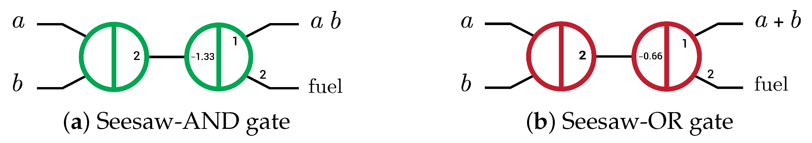
Logic gates were implemented using SDR by three main methods: The first implementation was the seesaw gate by Lulu Qian and Erik Winfree in 2011 [6,14]. This gate has three operations: seesawing (reversible), thresholding (irreversible), and reporting (irreversible) operations where the reversible operation is the operation that can produce the inputs through the outputs and vice versa, while the irreversible operation produces only the outputs through the inputs. Seesaw gate acts as AND and OR gates directly as shown in Figure 1 by changing the thresholding concentration only. Seesaw-AND and seesaw-OR gates have become the basic units (elementary gates) to implement any Boolean function by converting the function to an equivalent circuit with only AND and OR gates, using dual-rail logic because it is not possible to perform a NOTgate in the SDR system [6,14]. The seesaw gate took hours to compute the outputs of the four-bit square root circuit by using about 130 strands in the operation [14].
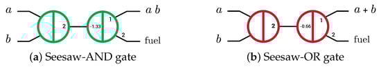
Figure 1.
Abstract diagram of two-layer DNA-based seesaw AND/OR logic implementations. Small numbers indicate relative concentrations of initial species (2× input, 1.33× and 0.66× threshold, 1× gate:output complex and 2× fuel) [6].
The second implementation was single-stranded gates by Tianqi Song et al. [9] in 2019. This implementation performs Boolean circuits in dual-rail logic by single-stranded-AND and single-stranded-OR gates [9]. It took 25 min at most to compute the outputs of the four-bit square root circuit by using about 37 strands in the operation [9].
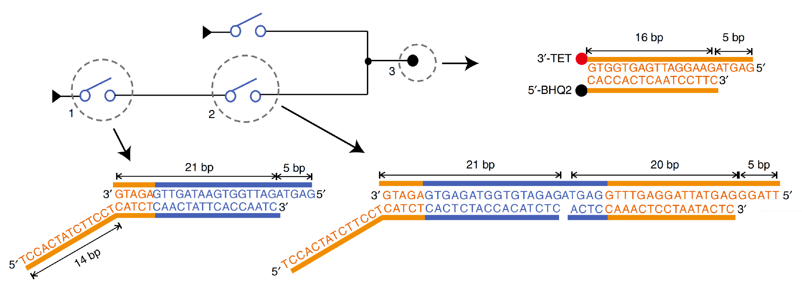
The third implementation was DNA-based switching circuits (DSC) by Fei Wang et al. [1] in 2020. This experiment follows a different technique to implement logic circuits which is Shannon’s switching circuit [28]. A switch is synthesized in DNA as a partial double-stranded that represents the OFF (0) state as shown in Figure 2, and after the switch responds to the required signals, it turns to fully double-stranded which represents the ON (1) state, then it generates a signal for the next switch to turn it ON, and so on.

Figure 2.
DNA-based switch implementation [1]. A switch is a partial double-stranded that represents the OFF (0) state, and after the switch responds to the required signals, it turns to fully double-stranded that represents the ON (1) state then it generates a signal for the next switch to turn it ON.
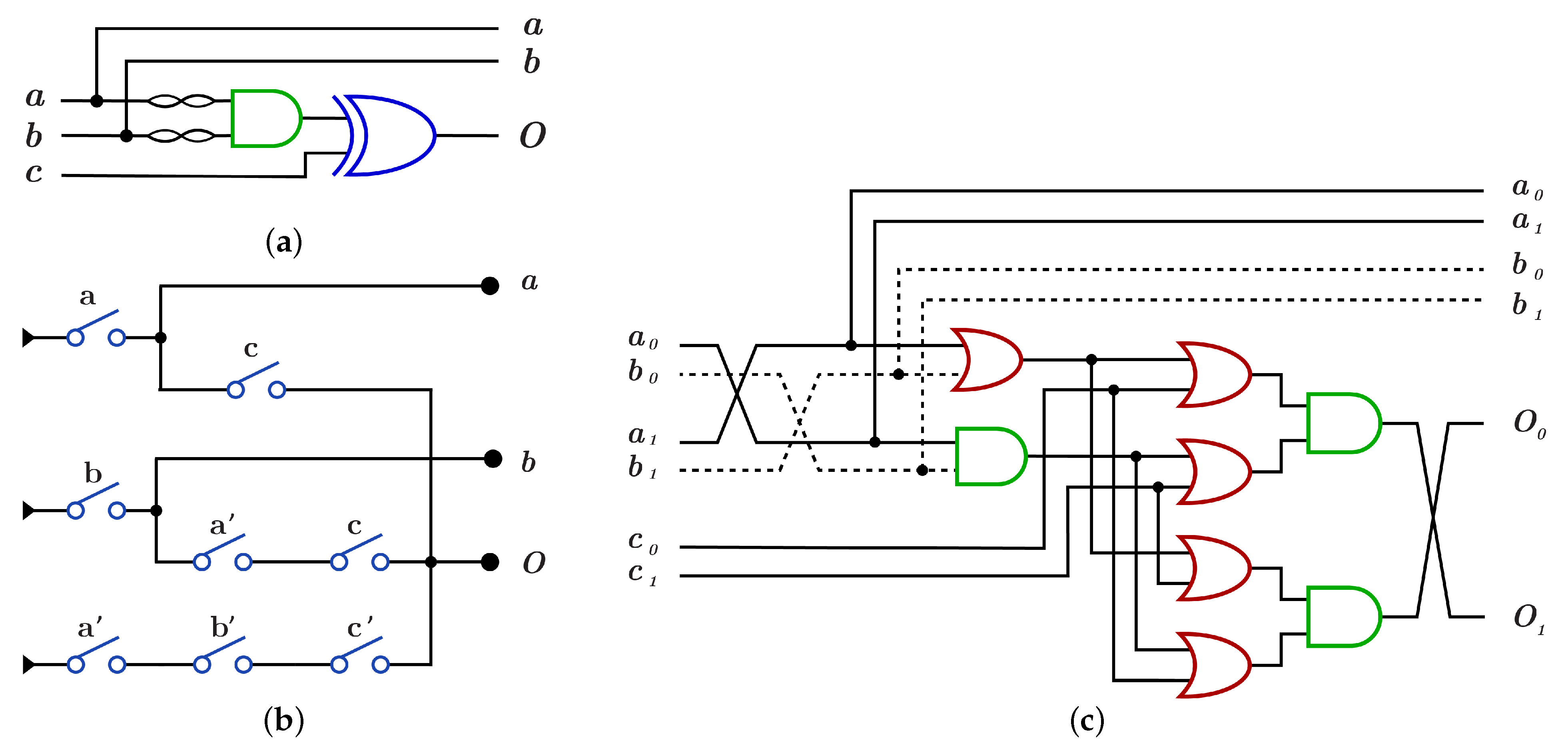
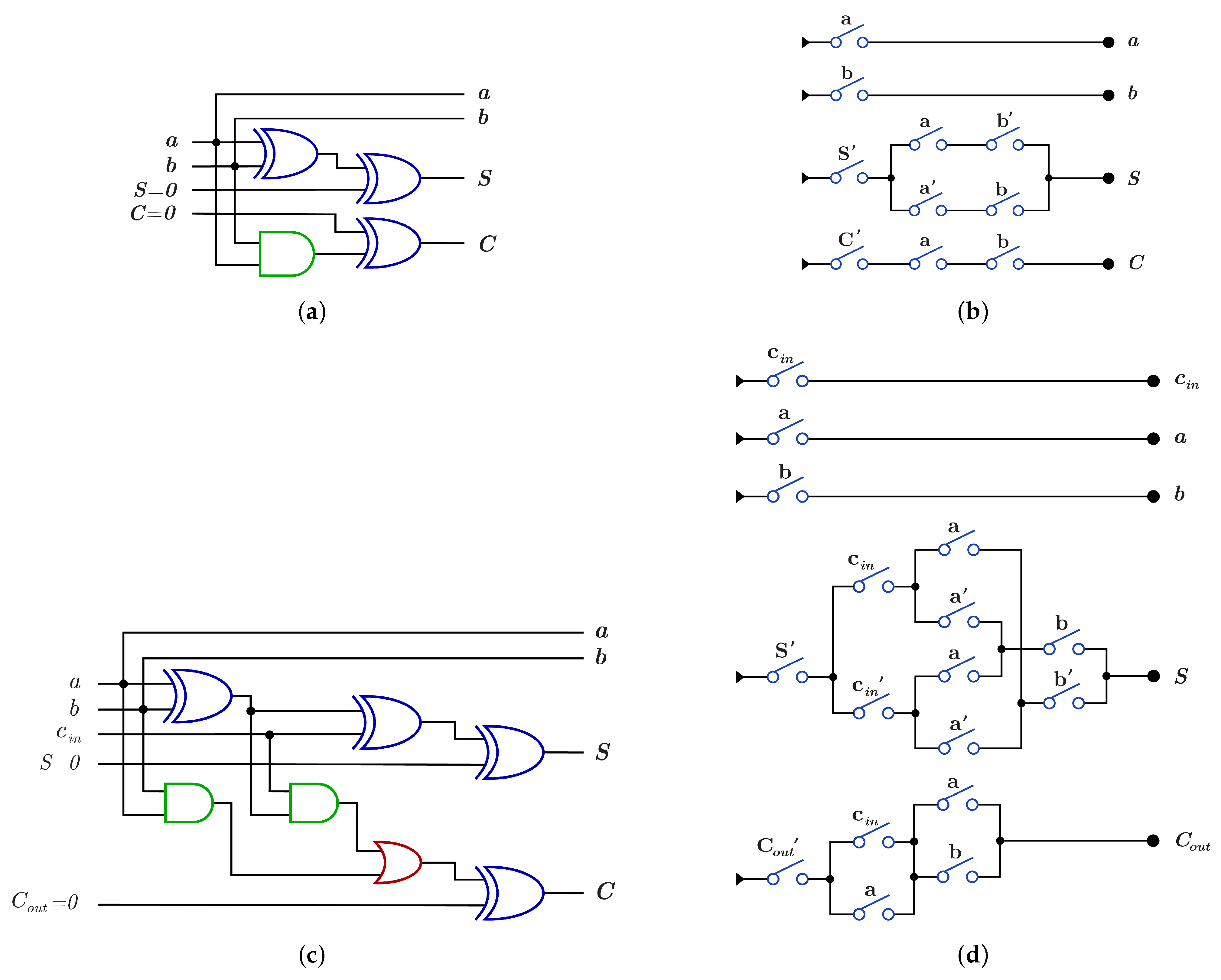
A Boolean function is implemented using DSC by mapping each term in the function Boolean expression into one or more switches, then these switches are connected as a circuit to perform the whole circuit function. DNA-based DSC circuit is an implementation of the true terms in the circuit truth table. The AND and OR gates are synthesized as a partially double-stranded DNA as shown in Figure 3a for AND gate and Figure 3b for OR gate. Another method for synthesizing AND and OR gates is by using multi-switches; serial switches for AND gate as shown in Figure 3c and parallel switches for OR gate as shown in Figure 3d.
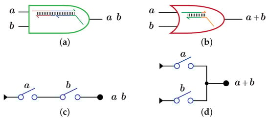
Figure 3.
DNA-based AND, OR gates using Strand Displacement Reactions (SDR) and Switches (DSC) [1]. (a) SDR implementation for AND gate. (b) SDR implementation for OR gate. (c) DSC implementation for AND gate. (d) DSC implementation for OR gate.
Dual-rail logic implementation for a circuit generates the full output as ON (1) or OFF (0) states, while in DSC implementation if the reporter responds to a signal then the output is 1 while if the reporter doesn’t respond to any signal, the output is 0. A Boolean function is implemented by two methods, by using the dual-rail logic with only AND and OR gates and by converting the circuit’s boolean expression into switches that perform the circuit function. Using DSC, it took less than 10 min to compute the outputs of the four-bit square root circuit by using at most 24 strands in the operation [1].
3. Reversible Logic Gates and Circuits Using DNA
This section presents the reversible gates and circuits with their DNA construction using SDR system, then it presents a comparison between the DNA cost and quantum cost for each gate or circuit implementation.
3.1. Reversible Gates and Circuits
The reversible gates such as NOT (N), CNOT (C), and Toffoli (T) gates are applicable on quantum computers and can operate on n-bits. The size of reversible gates and circuits that are implemented in this paper is 3-bits because gives 40,320 possible Boolean functions which is the most efficient circuit size that can be experimented and tested, unlike inputs/outputs circuits. Each gate or circuit has a quantum cost that is defined as follows:
Definition 1 (Quantum Cost (QC)).
Quantum Cost for a quantum circuit is (2-bit) elementary quantum gates that form the circuit after the decomposition of all (3-bit) or higher gates. The QC for a (1-bit) gate is 0, for a 2-bit gate is 1, and for a 3-bit gate is the count of 2-bit elementary gates that form the gate [29]. This term is used to measure the complexity of implementing the reversible circuits on real quantum computer.
The N gate, such as , as shown in Figure 4, is a 1-bit gate with ; it inverts the input value from 0 to 1 and vice versa. The N gate can act on any wire of the 3 input/output circuits, giving different functions as shown in Equation (1).
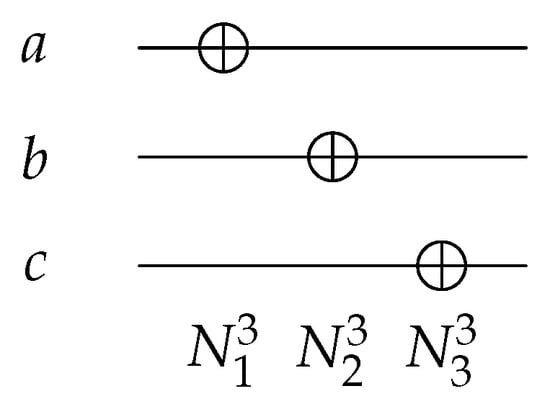
Figure 4.
Reversible NOT Gates.
For each of the following gates, the input can be a control bit or a target bit. The control bit has two conditions: an open condition (small white circle) and a closed condition (small black circle). In the open condition, the control bit is in true form if its value is set to 0, while in the closed condition, the control bit is in true form if its value is set to 1. The value of the target bit is inverted only if the control bit(s) are in true form.
The C gate such as as shown in Figure 5 is a 2-bit gate with ; it inverts the target bit value if the control bit is in its true form. For 3 input/output circuits, C gate can act on any two wires with different conditions for the control, a closed () or an open () control as shown in Figure 5. Equation (2) shows the function for some of C gates on different wires for 3 input/output circuits.
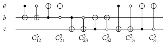
Figure 5.
Reversible CNOT Gates.
Using three C gates, Swap gate is implemented to swap two input values with as shown in Figure 6.
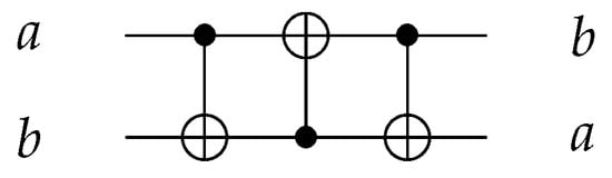
Figure 6.
Reversible SWAP Gate using three gates.
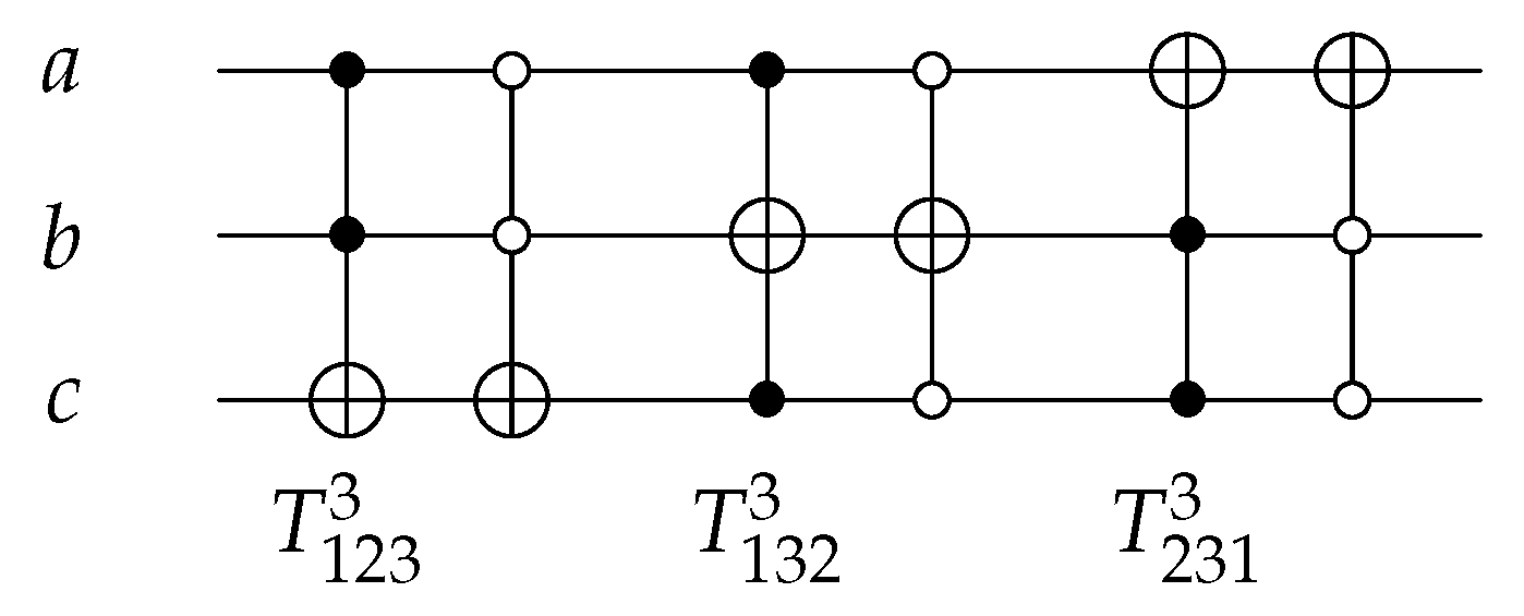
The T gate, such as as shown in Figure 7, is a 3-bit gate with . The value of the target bit is inverted if the control bits are in true form. The position of the target bit, with the control bits condition, changes the T gate function over the 3 input/output circuits as shown in Equation (3), where is the abbreviation of closed-closed T gate, and is the abbreviation of open-open T gate.
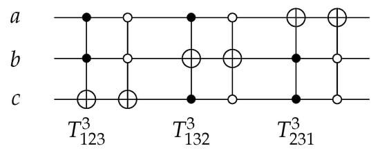
Figure 7.
Reversible TOFFOLI Gates.
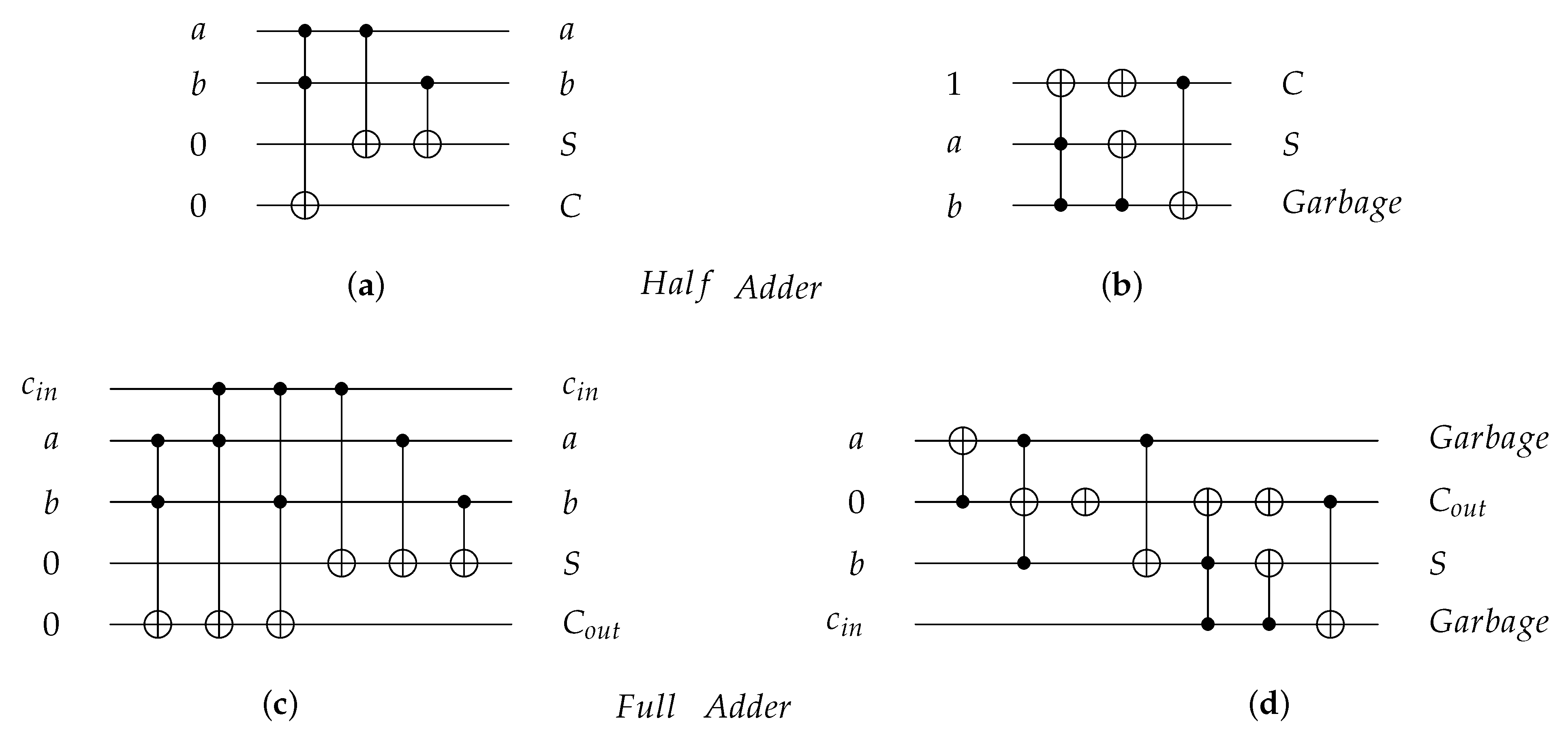
As an application for reversible gates, Figure 8 presents four reversible implementations for 1-bit Half adder and 1-bit Full adder circuits. The Half adder circuit implementations are shown in Figure 8a,b with for both implementations equal to 7, while the Full adder circuit implementations are shown in Figure 8c,d with equal to 18 and 14, respectively. Figure 8b,d for 1-bit Half adder and 1-bit Full adder, respectively, are implemented using gate [30] with for Half Adder circuit after cost optimization in Figure 8b and for Full Adder circuit after cost optimization in Figure 8d [31].
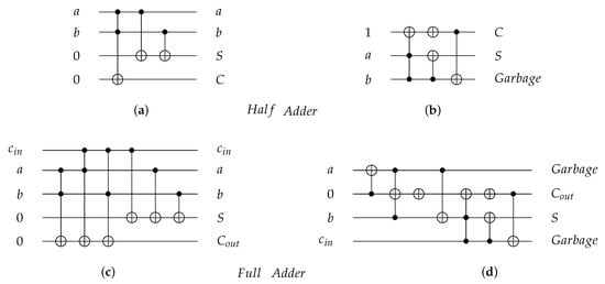
Figure 8.
Reversible implementations for 1-bit Half Adder and 1-bit Full Adder circuits. (a) 1-bit Half Adder reversible circuit using and gates with quantum cost () = 7. (b) 1-bit Half Adder reversible circuit using gate with = 7 before cost optimization and = 4 after cost optimization [31]. (c) 1-bit Full Adder reversible circuit using and gates with = 18. (d) 1-bit Full Adder reversible circuit using gate with = 14 before cost optimization and = 8 after cost optimization [31].
3.2. DNA-Based Reversible Gates and Circuits
The gate synthesization process is based on the logic equations that describe the gate behavior. Each gate from Section 3.1 is constructed using DNA in this section using two reversible methods. The first method involves DNA-based logic gates by using DNA-based AND gate and DNA-based OR gate which are implemented as in Figure 3a,b and these implementations are experimentally tested in detail in [1]. The second method involves using DNA switches , where switching circuits are also experimentally implemented and tested in ref. [1] and Figure 2 shows the implementation of a DNA switch. For each proposed construction, DNA cost is calculated as follows:
Definition 2 (DNA Cost (DNAC)).
DNA cost for a gate or a circuit is the count of layers that perform the gate or the circuit function. Layers of a circuit are the depth or the number of levels that construct the circuit diagram using dual-rail logic or switches as the gates in the same layer work in parallel.
Each layer has equal to 1 regardless of the number of elementary gates (DNA-based AND gate and DNA-based OR gate) or switches that it contains because the contents of each layer work in parallel.
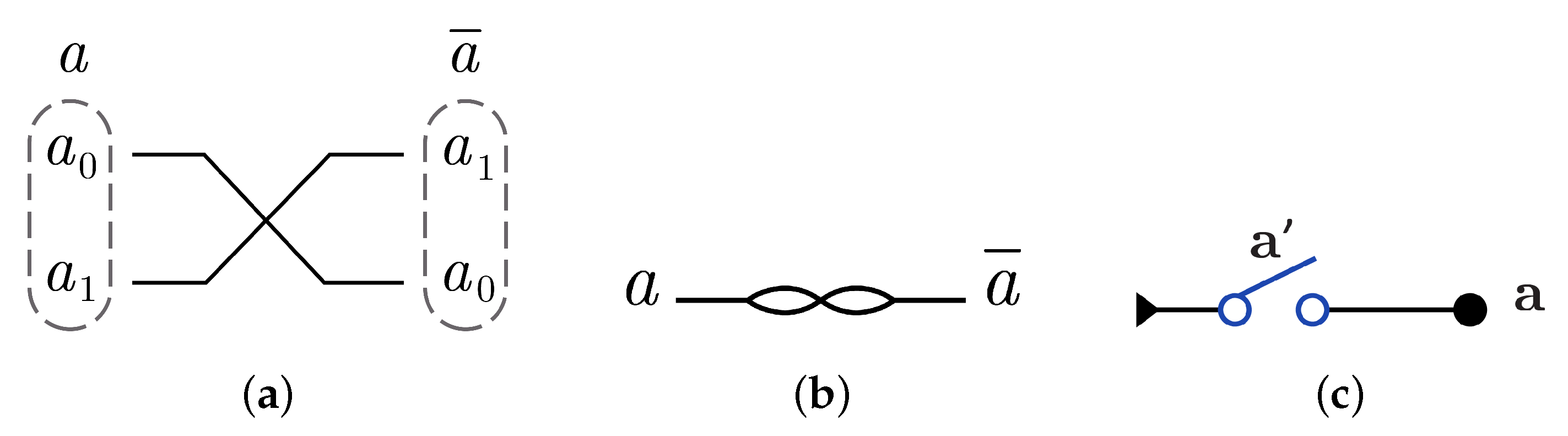
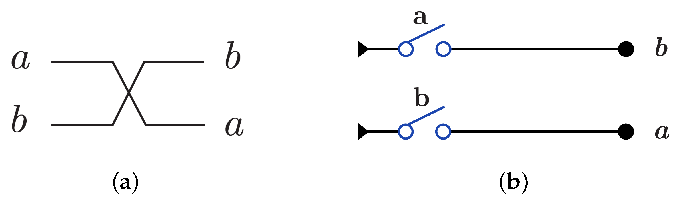
N gate construction using in dual-rail logic mode just involves swapping between the wires that represent the input as gate cannot be implemented using dual-rail logic in another way. N gate is represented using in dual-rail logic as shown in Figure 9a by only swapping the input wires which gives and it is symbolized as in Figure 9b, while N gate using is implemented by one switch in one layer as shown in Figure 9c with .

Figure 9.
DNA constructions for gate. (a) gate construction using in dual-rail logic. (b) Symbolized form for gate in . (c) gate construction using .
gate is constructed using by XOR gate as in Figure 10a with because it consists of two layers in the dual-rail logic mode as in Figure 10b. implementation using requires two layers with four switches as shown in Figure 10c with .
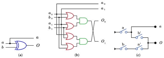
Figure 10.
DNA constructions for gate with closed control. (a) gate construction using . (b) construction details in dual-rail logic. (c) gate construction using .
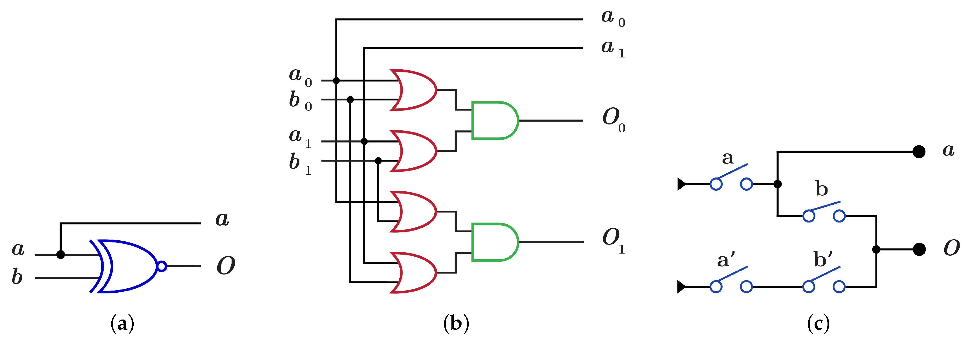
The construction of using is done by using XNOR gate as in Figure 11a which differs from dual-rail construction by swapping the two wires of the output O as shown in Figure 11b with , while implementation using requires two layers with the same four switches but in different order as shown in Figure 11c with .
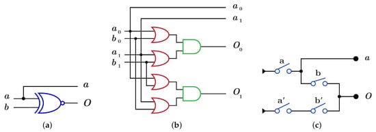
Figure 11.
DNA constructions for gate with open control. (a) gate construction using . (b) construction details in dual-rail logic. (c) gate construction using .
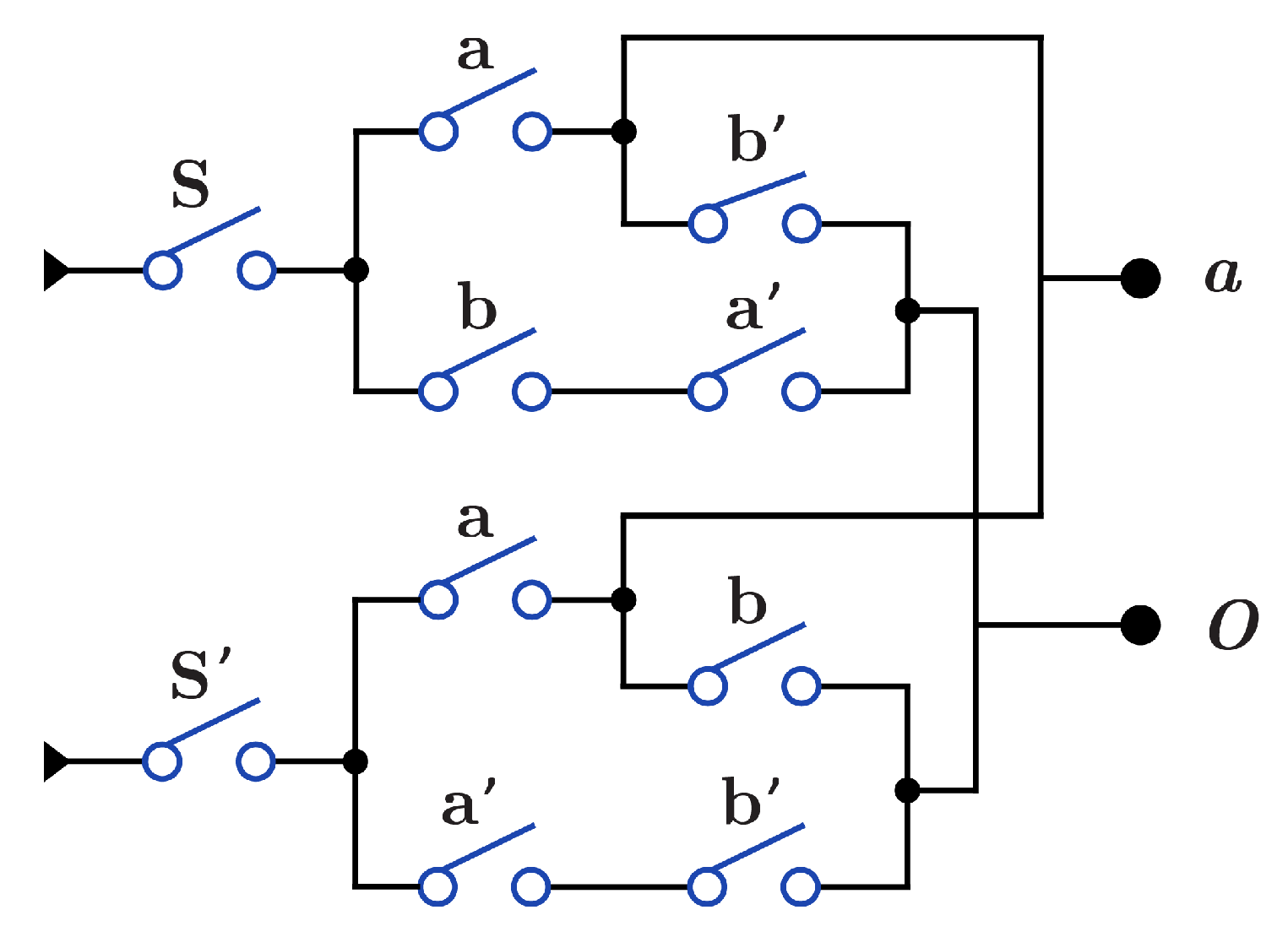
Figure 12 presents construction for gate that acts as both and through the S switch with . When , the circuit acts as , while when (), the circuit acts as . construction for is the same as in Figure 10b and Figure 11b, with swapping of the output O wires and .
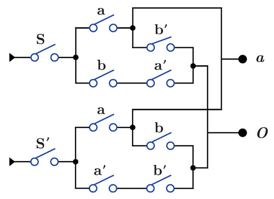
Figure 12.
DNA construction for gate using .
Swap gate is constructed using with by swapping the wires as in Figure 13a and implemented with using by one layer with two switches as in Figure 13b.
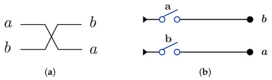
Figure 13.
DNA constructions for SWAP Gate. (a) SWAP gate construction using . (b) SWAP gate construction using .
The construction of using is done by using AND gate for the control bits and XOR gate for the target bit as shown in Figure 14a with because of the dual-rail three layers with five OR gates and three AND gates as in Figure 14c, while the construction using requires three layers with eight switches and as shown in Figure 14b.
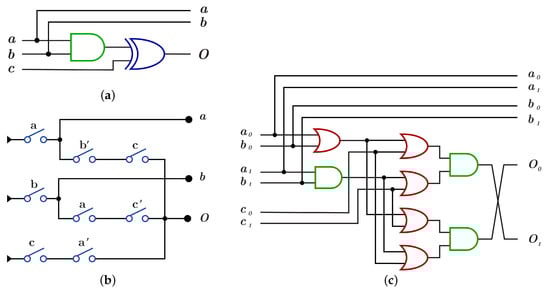
Figure 14.
DNA constructions for closed controls gate. (a) gate construction using . (b) gate construction using . (c) construction details in dual-rail logic.
construction using differs from construction by applying NOT operation on each control bit before it enters to AND gate as in Figure 15a,c with , while using , construction has three layers with eight switches different from switches as shown in Figure 15b with .
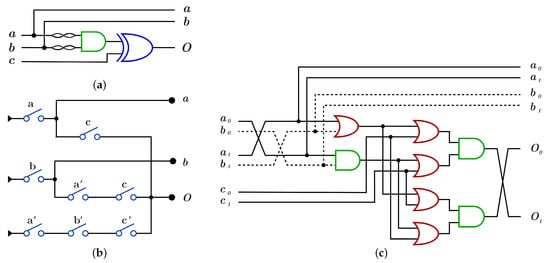
Figure 15.
DNA constructions for open controls gate. (a) gate construction using . (b) gate construction using . (c) construction details in dual-rail logic.
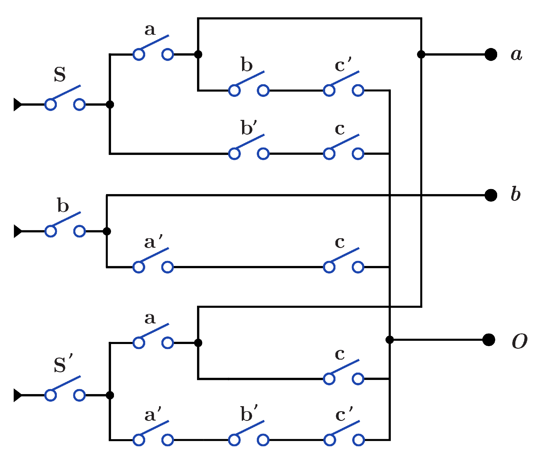
Figure 16 presents circuit for gate that acts as both and through the S switch with . When , the circuit acts as , while when (), the circuit acts as . Circuit paths in Figure 16 that start with input b are common paths for and gates. construction for has and is similar for open and closed states as in Figure 14a and Figure 15a, applying N for each open control bit.
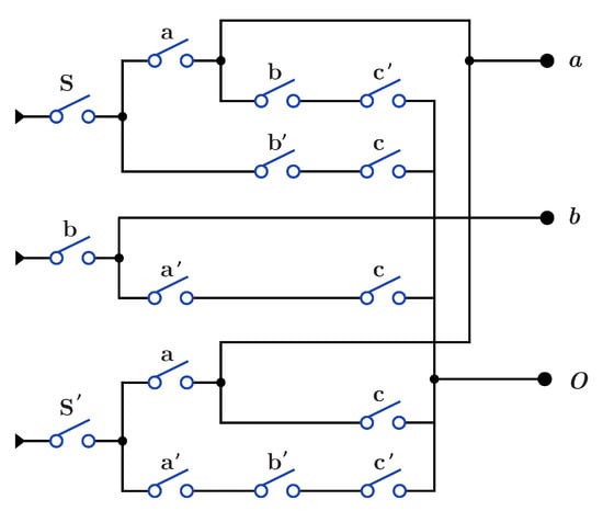
Figure 16.
DNA construction for gate using .
As an application for DNA-based reversible gates, Figure 17a,b show the proposed construction for the 1-bit Half adder circuit with using and using , respectively. Figure 17c,d presents the proposed construction for 1-bit Full adder circuit with using and using , respectively.
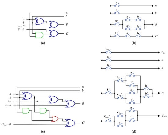
Figure 17.
DNA constructions for 1-bit Half Adder and 1-bit Full Adder. (a) construction for 1-bit Half Adder circuit with . (b) construction for 1-bit Half Adder circuit with . (c) construction for 1-bit Full Adder circuit with . (d) construction for 1-bit Full Adder circuit with .
Table 1 shows a comparison between for reversible implementations and for , constructions for reversible gates and circuits in Section 3. The data in Table 1 are obtained by calculating the circuit cost according to the circuit construction, which is constructed using reversible quantum gates or constructed using DNA techniques. This comparison shows the efficiency of DNA cost constructions for logic circuits as opposed to quantum reversible implementations as shown for Half and Full adder circuits.

Table 1.
Comparing between quantum cost () and DNA cost () for different reversible gates and circuits.
4. Proposed Novel Library of DNA Constructs for Reversible Circuits
The universal reversible gate library (URGL) is a universal set of reversible gates. This set is used in synthesizing all circuits instead of synthesizing each circuit individually by different implementations. A library that consists of n-bit reversible gates (generators) is used to synthesize arbitrary reversible circuits with n inputs/outputs, which builds a whole symmetric group of permutations of degree n.
Depending on this approach many libraries were presented with 3-bit circuits as the reversible circuits over 3-bits form a permutation group of size 40,320 (), which is a subset of the symmetric group. The presented libraries are such as , , , , , , , , , , , , , as P is the Peres gate, F is the Fredkin gate, is the Generalized Toffoli gate [19], and , , , are the proposed libraries in [32,33], any universal reversible libraries is considered as the generator of the permutation group [18,19].
Each proposed library is competing with the other libraries by generating the required circuit using fewer generators (length) or less manufacturing cost than the previous proposals, while the average length and the average cost of all the generated circuits using a specific library is calculated using the GAP software [34].
4.1. The Novel Proposed URGL (K Library)
This section proposes an n-bit URGL () for synthesizing any n input/output reversible circuit. The number of generators for this library that are used in the synthesization process is equals to when and n is the number of bits for the reversible circuits that are desired to build.
4.1.1. Library
For 1-bit circuits, the library is universal for the two possible circuits and has one generator (). gate is acting as N gate that inverts the input value with as shown in Figure 18; the gate function is shown in Equation (4).
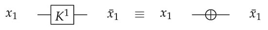
Figure 18.
Library Reversible Generator with .
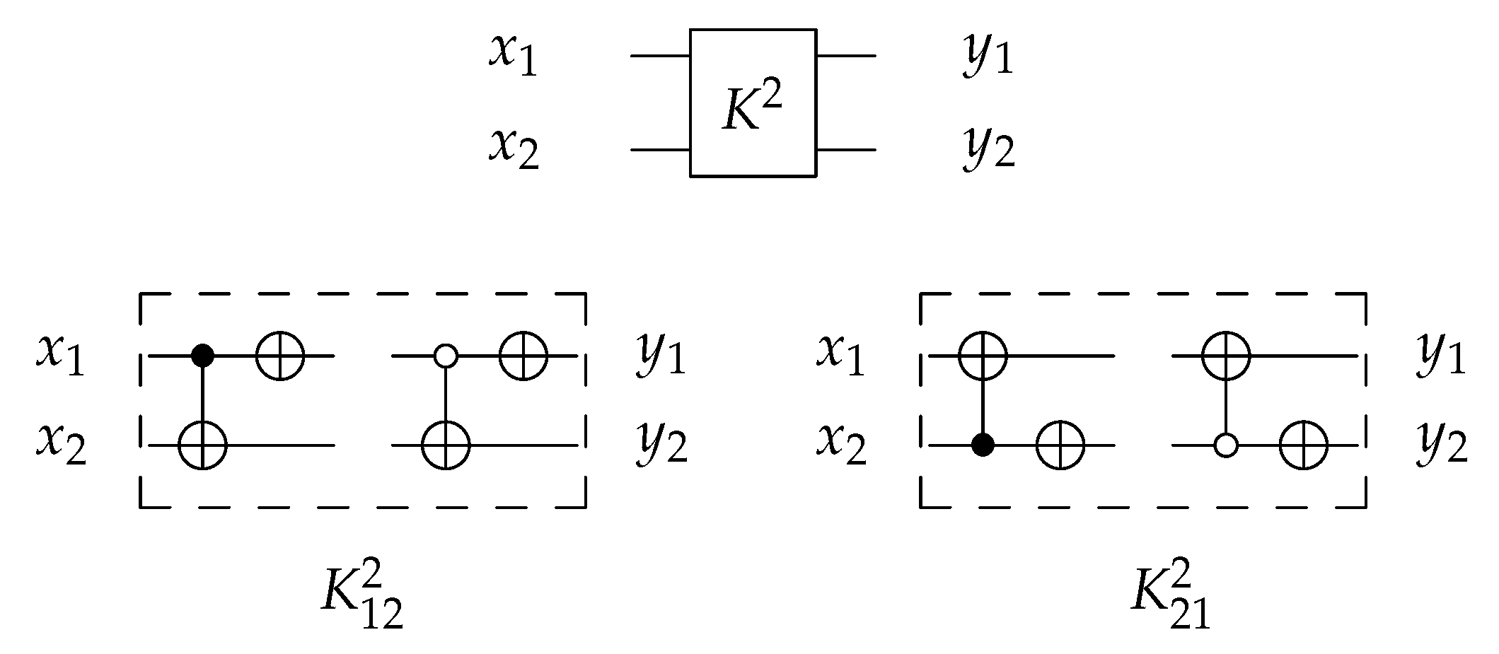
4.1.2. Library
For 2-bit circuits, the library is universal for 24 possible circuits and has four generators and with open () and closed control (). The 2-bit gate is the merging of C and N gates into one gate () with for each generator. The library generators are shown in Figure 19 and the function of each generator is shown in Equation (5). To implement any generator in the reversed direction, the gates must be implemented in a reverse order by applying N gate first, then C gate.
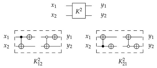
Figure 19.
Library Reversible Generators with for each generator.
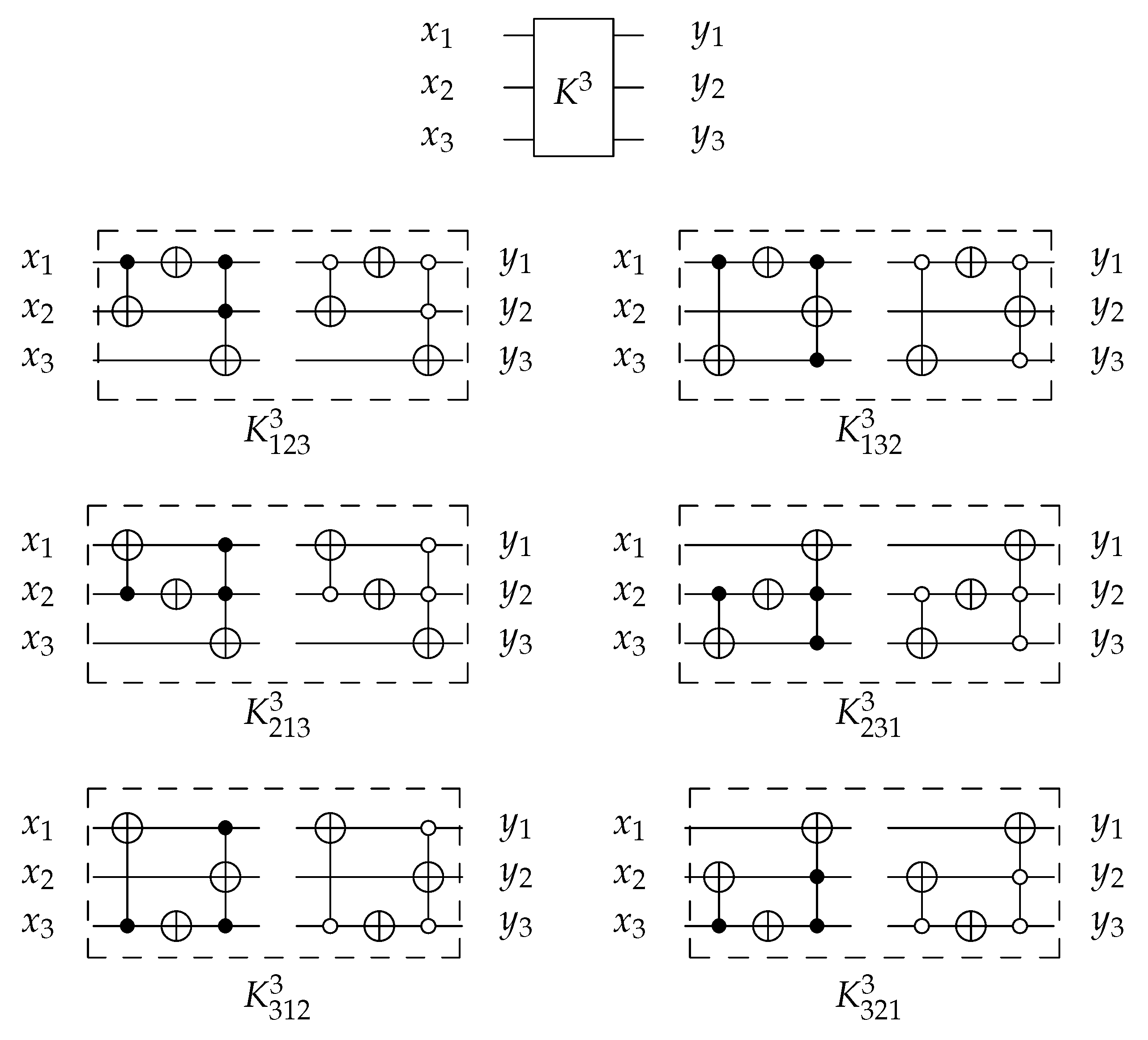
4.1.3. Library
For 3-bit circuits, the library is universal for 40,320 possible circuits and has twelve generators , , , , , and with open and closed controls. gate is the merging of C, N, and gates into one gate () with for each generator. The library generators are shown in Figure 20 and the function of each generator is shown in Equation (6). To implement any generator in the reversed direction, the gates must be implemented in a reverse order by applying first, then N gate, and finally C gate.
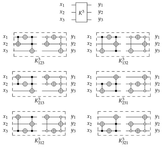
Figure 20.
Library Reversible Generators with for each generator.
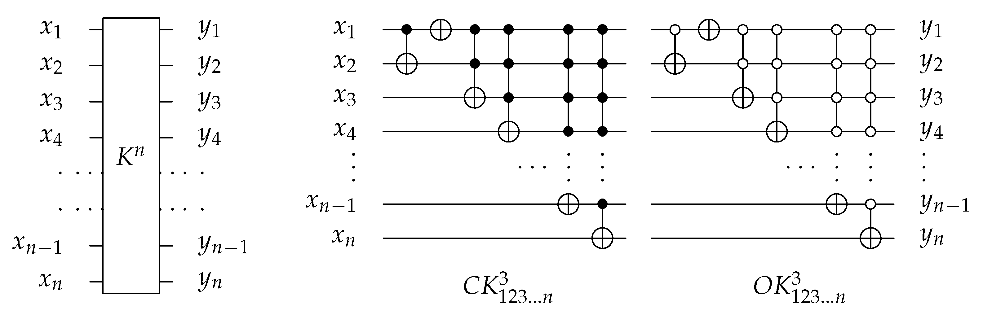
4.1.4. Library
For n-bit circuits, the library is universal for possible circuits and has generators with open and closed controls. The library is extended by at the end of gate. It merges the function of C, N, , …, , gates into one gate () with for each generator. Figure 21 shows as an example of extendable library generator. To implement any generator in a reversed direction, the gates must be implemented in a reverse order as follows: , , …, , then N, and finally C gate.
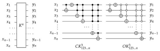
Figure 21.
The decomposition of reversible generator.
4.2. DNA-Based K Library
This section constructs the proposed K library using .
4.2.1. Library
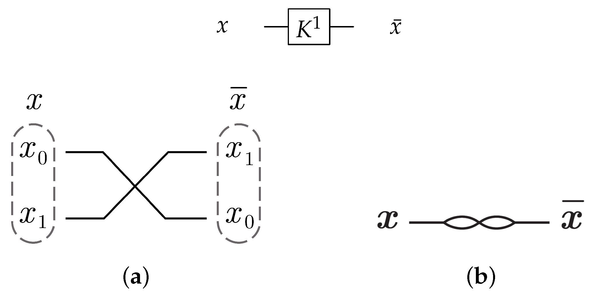
For the 1-bit gate library, gate constructs by swapping the input wires in dual-rail logic mode as shown in Figure 22a. gate is symbolized as in Figure 22b with .
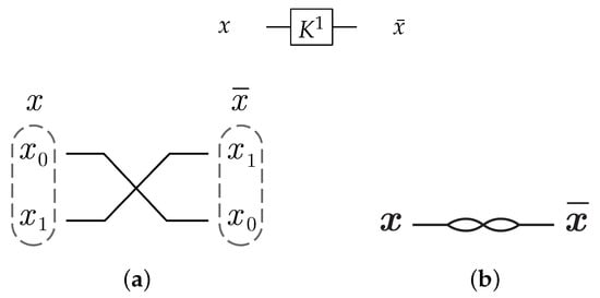
Figure 22.
DNA construction for gate library with . (a) construction for gate in dual-rail logic. (b) Symbolized form for gate in .
4.2.2. Library
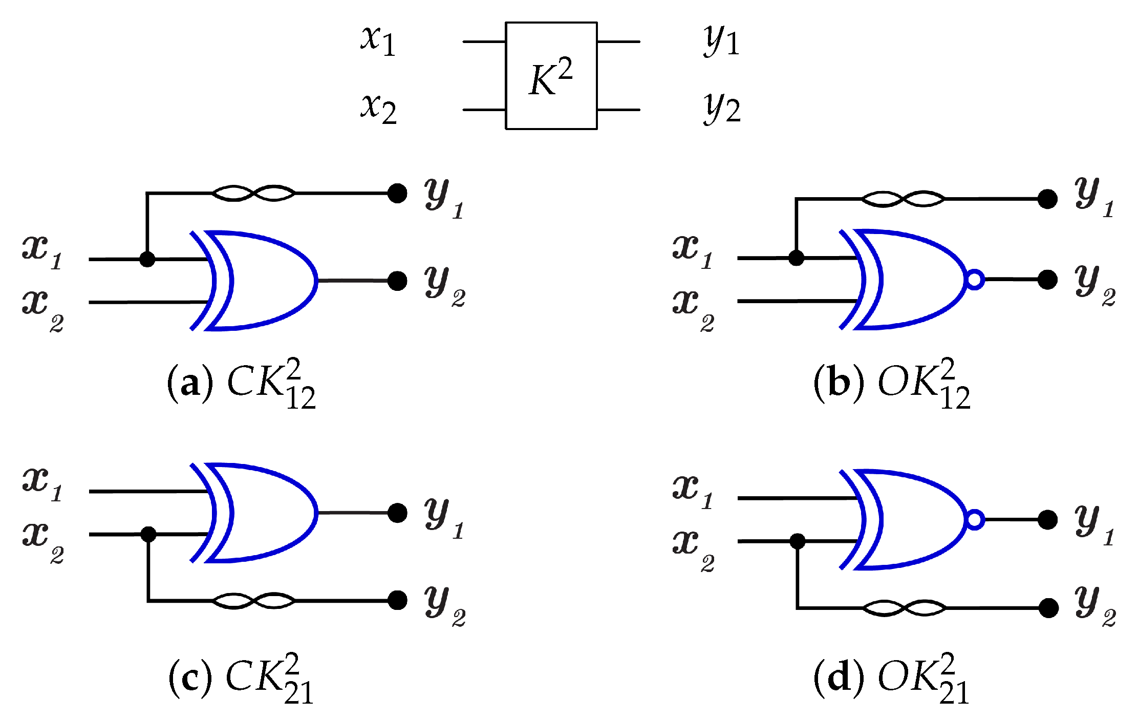
For 2-bit gate library, constructs by combining C and N gates, in other words by combining of and N gates as in Figure 23 that shows the implementations of the four generators for library with for each generator. To run any generator with a reversed direction, the gates are applied in a reverse order by running N gate first then gate.
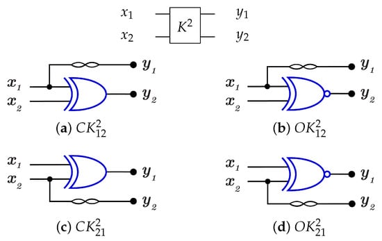
Figure 23.
DNA construction for library generators with for each generator. (a) construction for gate. (b) construction for gate. (c) construction for gate. (d) construction for gate.
4.2.3. Library
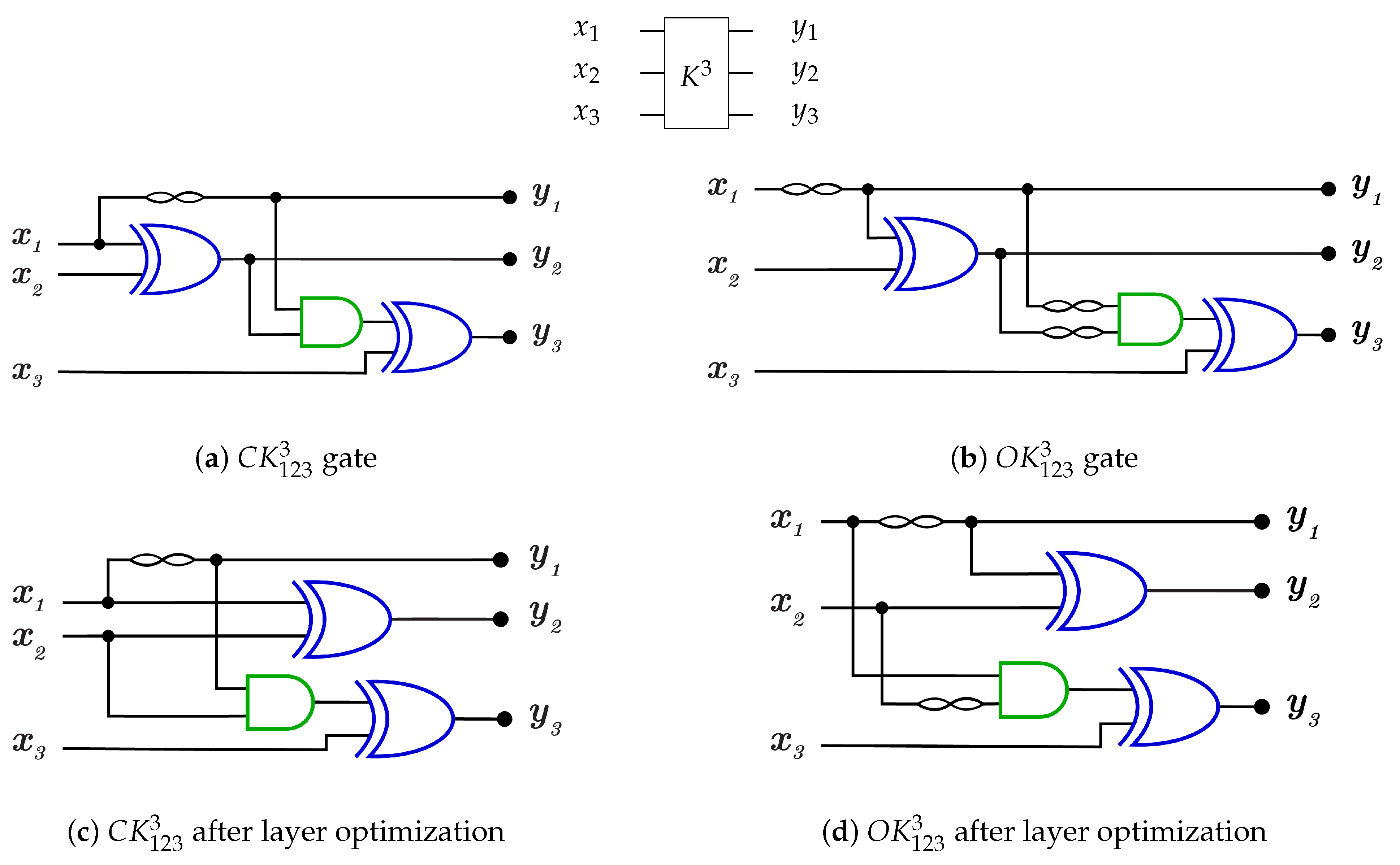
For 3-bit gate library, is constructed by a combination of N, , and gates. for each generator is equal to 5 as it is the sum of for N, C, gates. and are constructed as in Figure 24a,b with but some layers can be merged to work in parallel to reduce the generator cost down to 3 as shown in Figure 24c,d for and , respectively, with . For more details Table 2 presents the three layers in action for and in forward and backward directions.
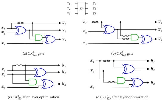
Figure 24.
DNA construction for generator. (a) construction for gate with . (b) construction for gate with . (c) construction for gate after layer optimization with . (d) construction for gate after layer optimization with .
Table 2.
gate layers in action.
library is a universal reversible library, as is the sublibrary () that contains six generators from as follows: , , , , , and with for each generator after layer optimization.
4.2.4. Library
For n-bit library, the extendable gate is constructed by a combination of N, , gates with for each generator, as it is the sum of for , , …, , gates as is the for the extended Toffoli gate that acts on n-bits.
Table 3 shows the for the extended Toffoli gates starting from as it is calculated according to the number of AND gates that are used to perform function according to the number of controls. For library, for each generator without layer optimization. For library, for each generator without layer optimization, and so on.
Table 3.
for Extended T gates.
As shown through this section with DNA constructions for K library generators for n-bits, Table 4 presents a comparison between and for the library generators. Note that for generators is calculated by and is calculated by . The results show that DNA constructions have a lower cost than for reversible implementation, which means it is better to build any reversible circuit using DNA than other implementations.
Table 4.
Comparing between and for library generators for building n reversible circuits.
5. Results
Section 3 and Section 4 show that implementing reversible circuits such as quantum circuits in DNA computing gives circuits with manufacturing DNA cost less than quantum cost based on the results shown in Table 1 and Table 4. Implementing proposed DNA reversible circuits is based on the chemical techniques and experiment details that are successfully tested in [1].
This section also presents a comparison between library and the other three input/output libraries according to the average of , average of , and average length of the generated circuits from each library.
The average of and average of are calculated by entering the following data into a Gap program (program inputs): the permutations that represent each library generator and the or for each permutation. The program generates the 40,320 possible circuit for 3-bit libraries using the given permutations (library generators), then calculates the average length of the generated circuits, which is fixed for each library, and the average or average based on the data inputs to the program ( or ) (program outputs).
The comparable libraries are with 6 generators, with 12 generators, with 6 generators, with 6 generators, with 9 generators, with 6 generators, with 9 generators, the proposed with 6 generators, and the proposed with 12 generators.
Table 5 presents the outputs of the Gap programs. The outputs show that the average length of the generated circuits is fixed for quantum and DNA implementations because of fixed generators for each library which form the same permutations, while the average cost is different between quantum and DNA implementations. For each of the comparable libraries, the average of before layer optimization is less than the average of , which shows the efficiency of DNA implementations for n-bit reversible circuits.
Table 5.
Comparing between the 3-bit universal reversible gate libraries according to library size, average quantum cost, average DNA cost, and average length.
6. Conclusions
This paper proposes theoretically two reversible methods for constructing reversible gates and circuits on DNA computers using DNA strand displacement reactions (SDRs) and the Toehold exchange principle based on real successful chemical experimented in vitro with details mentioned in ref. [1].
The first method involves constructing reversible circuits using dual-rail logic () and the second method involves using switching circuits ().
Logic circuit construction using DNA reduces the cost of the overall circuit because each single logic gate in dual-rail logic or switch has = 1 and each logic circuit has equal to the number of the circuit layers because of the DNA parallelism property as shown in the Half Adder and the Full Adder circuits. In the Half Adder circuit shown in Figure 8a,b, the before cost optimization and after cost optimization but when the circuit is constructed using DNA as shown in Figure 17a,b, for the constructed circuit using and using without layer optimization. Also, the Full adder circuit in Figure 8c,d has before optimization and after optimization but when the circuit is constructed using DNA, the constructed circuit has using and has using without optimization.
This paper also proposed a novel universal reversible extendable library (K library) for synthesizing n-bit circuits on quantum or DNA computers with less average length, average quantum cost, and average DNA cost than the previous proposed libraries. This library uses 1 generator for 1-bit circuits, 4 generators for 2-bit circuits, and 12 generators for 3-bit circuits. achieves average length = 4.857 which is less than the average length of the other libraries shown in Table 5. has an average , average without optimization, and average after layer optimization which shows the efficiency of DNA implementations. The construction using DNA-based SDR gates has advantages to build circuits within a small scale in test tubes with enzyme-free reactions, less average cost, and less average length than quantum implementations to get the correct computational output for each circuit.
Author Contributions
Conceptualization, M.R. and A.Y.; supervision, A.Y.; software M.R.; validation M.R. and A.Y.; writing the paper, M.R. and A.Y. All authors have read and agreed to the published version of the manuscript.
Funding
This research was funded by the Academy of Scientific Research and Technology (ASRT), Egypt, Grant No 6560.
Acknowledgments
This paper was supported financially by the Academy of Scientific Research and Technology (ASRT), Egypt, under initiatives of Science Up Faculty of Science (Grant No 6560). (ASRT) is the 2nd affiliation of this research.
Conflicts of Interest
The authors declare that they have no conflict of interest in preparing this article.
References
- Wang, F.; Lv, H.; Li, Q.; Li, J.; Zhang, X.; Shi, J.; Wang, L.; Fan, C. Implementing digital computing with DNA-based switching circuits. Nat. Commun. 2020, 11, 121. [Google Scholar] [CrossRef] [Green Version]
- Jones, N.C.; Pevzner, P. Introduction to Bioinformatics Algorithms; MIT Press: Cambridge, MA, USA, 2004. [Google Scholar]
- Watada, J. DNA Computing and Its Application; Springer: Berlin/Heidelberg, Germany, 2008; pp. 1065–1089. [Google Scholar]
- Adleman, L.M. Molecular computation of solutions to combinatorial problems. Science 1994, 266, 1021–1024. [Google Scholar] [CrossRef] [Green Version]
- Lipton, R. DNA solution of hard computational problems. Science 1995, 268, 542–545. [Google Scholar] [CrossRef] [Green Version]
- Qian, L.; Winfree, E. A simple DNA gate motif for synthesizing large-scale circuits. J. R. Soc. Interface 2011, 8, 1281–1287. [Google Scholar] [CrossRef] [Green Version]
- Katz, E.; Poghossian, A.; Schöning, M.J. Enzyme-based logic gates and circuits—Analytical applications and interfacing with electronics. Anal. Bioanal. Chem. 2017, 409, 81–94. [Google Scholar] [CrossRef] [PubMed]
- Khoshkhahesh, A.; Ebrahimi, S.; Sabbaghi-Nadooshan, R. Designing and Optimizing DNA Reversible Adders and Adder/Subtractors. BioNanoScience 2018, 8, 118–130. [Google Scholar] [CrossRef]
- Song, T.; Eshra, A.; Shah, S.; Bui, H.; Fu, D.; Yang, M.; Mokhtar, R.; Reif, J. Fast and compact DNA logic circuits based on single-stranded gates using strand-displacing polymerase. Nat. Nanotechnol. 2019, 14, 1075–1081. [Google Scholar] [CrossRef]
- Goldman, N.; Bertone, P.; Chen, S.; Dessimoz, C.; LeProust, E.M.; Sipos, B.; Birney, E. Towards practical, high-capacity, low-maintenance information storage in synthesized DNA. Nature 2013, 494, 77–80. [Google Scholar] [CrossRef] [PubMed] [Green Version]
- Organick, L.; Ang, S.D.; Chen, Y.J.; Lopez, R.; Yekhanin, S.; Makarychev, K.; Racz, M.Z.; Kamath, G.; Gopalan, P.; Nguyen, B.; et al. Random access in large-scale DNA data storage. Nat. Biotechnol. 2018, 36, 242–248. [Google Scholar] [CrossRef]
- Takahashi, C.N.; Nguyen, B.H.; Strauss, K.; Ceze, L. Demonstration of End-to-End Automation of DNA Data Storage. Sci. Rep. 2019, 9, 4998. [Google Scholar] [CrossRef] [Green Version]
- Seelig, G.; Soloveichik, D.; Zhang, D.Y.; Winfree, E. Enzyme-Free Nucleic Acid Logic Circuits. Science 2006, 314, 1585–1588. [Google Scholar] [CrossRef] [PubMed] [Green Version]
- Qian, L.; Winfree, E. Scaling Up Digital Circuit Computation with DNA Strand Displacement Cascades. Science 2011, 332, 1196–1201. [Google Scholar] [CrossRef] [Green Version]
- Song, X.; Eshra, A.; Dwyer, C.; Reif, J. Renewable DNA seesaw logic circuits enabled by photoregulation of toehold-mediated strand displacement. RSC Adv. 2017, 7, 28130–28144. [Google Scholar] [CrossRef] [Green Version]
- Yurke, B.; Turberfield, A.J.; Mills, A.P.; Simmel, F.C.; Neumann, J.L. A DNA-fuelled molecular machine made of DNA. Nature 2000, 406, 605–608. [Google Scholar] [CrossRef]
- Bennett, C.H. Logical Reversibility of Computation. IBM J. Res. Dev. 1973, 17, 525–532. [Google Scholar] [CrossRef]
- Vos, A.D. Reversible Computing—Fundamentals, Quantum Computing, and Applications; Wiley-VCH: Weinheim, Germany, 2010. [Google Scholar]
- Younes, A. On the universality of n-bit reversible gate libraries. Appl. Math. Inf. Sci. 2015, 9, 2579–2588. [Google Scholar]
- Song, T.; Wang, S.; Wang, X. The design of reversible gate and reversible sequential circuit based on DNA computing. In Proceedings of the 2008 3rd International Conference on Intelligent System and Knowledge Engineering, Xiamen, China, 17–19 November 2008; Volume 1, pp. 114–118. [Google Scholar]
- Sarker, A.; Ahmed, T.; Rashid, S.M.M.; Anwar, S.; Jaman, L.; Tara, N.; Alam, M.M.; Babu, H.M.H. Realization of Reversible Logic in DNA Computing. In Proceedings of the 2011 IEEE 11th International Conference on Bioinformatics and Bioengineering, Taichung, Taiwan, 24–26 October 2011; pp. 261–265. [Google Scholar]
- Sarkar, M.; Ghosal, P.; Mohanty, S.P. Minimal reversible circuit synthesis on a DNA computer. Nat. Comput. 2017, 16, 463–472. [Google Scholar] [CrossRef]
- Fratto, B.E.; Lewer, J.M.; Katz, E. An Enzyme-Based Half-Adder and Half-Subtractor with a Modular Design. ChemPhysChem 2016, 17, 2210–2217. [Google Scholar] [CrossRef] [PubMed]
- Bakshi, S.; Zavalov, O.; Halámek, J.; Privman, V.; Katz, E. Modularity of Biochemical Filtering for Inducing Sigmoid Response in Both Inputs in an Enzymatic AND Gate. J. Phys. Chem. B 2013, 117, 9857–9865. [Google Scholar] [CrossRef] [Green Version]
- Roy, P.; Dey, D.; Sinha, S.; De, D. Reversible OR Logic Gate Design Using DNA. In Proceedings of the Seventh International Conference on Bio-Inspired Computing: Theories and Applications (BIC-TA 2012); Bansal, J.C., Singh, P.K., Deep, K., Pant, M., Nagar, A.K., Eds.; Springer: New Delhi, India, 2013; pp. 355–366. [Google Scholar]
- Orbach, R.; Remacle, F.; Levine, R.D.; Willner, I. Logic reversibility and thermodynamic irreversibility demonstrated by DNAzyme-based Toffoli and Fredkin logic gates. Proc. Natl. Acad. Sci. USA 2012, 109, 21228–21233. [Google Scholar] [CrossRef] [Green Version]
- Genot, A.J.; Bath, J.; Turberfield, A.J. Reversible Logic Circuits Made of DNA. J. Am. Chem. Soc. 2011, 133, 20080–20083. [Google Scholar] [CrossRef]
- Shannon, C.E. A symbolic analysis of relay and switching circuits. Electr. Eng. 1938, 57, 713–723. [Google Scholar] [CrossRef] [Green Version]
- Yang, G.; Song, X.; Hung, W.N.N.; Perkowski, M.A.; Seo, C.J. Synthesis of reversible circuits with minimal costs. Calcolo 2008, 45, 193–206. [Google Scholar] [CrossRef]
- Montaser, R.; Younes, A.; Abdel-Aty, M. New Design of Reversible Full Adder/Subtractor Using R Gate. Int. J. Theor. Phys. 2019, 58, 167–183. [Google Scholar] [CrossRef] [Green Version]
- Montaser, R.; Younes, A.; Abdel-Aty, M. Improving the quantum cost of NCT-based reversible circuit. Quantum Inf. Process. 2015, 14, 1249–1263. [Google Scholar] [CrossRef]
- Montaser, R.; Younes, A.; Abdel-Aty, M. New Design of Universal Reversible Gate Library. Quantum Matter 2017, 6, 1–8. [Google Scholar] [CrossRef]
- Osman, M.; Younes, A.; Ismail, G.; Farouk, R. An Improved Design of n-Bit Universal Reversible Gate Library. Int. J. Theor. Phys. 2019, 58, 2531–2549. [Google Scholar] [CrossRef]
- GAP System for Computational Discrete Algebra, Version 4.11.0. 2020. Available online: https://www.gap-system.org/ (accessed on 2 June 2021).


Short Biography of Authors
 | Mirna Rofail obtained her BSc in Computer Science in 2016 from Faculty of Science, Alexandria University. Currently, she is a Computer Science Teaching Assistant in the Department of Mathematics and Computer Science, Alexandria University. She is a member in Alexandria Quantum Computing Group (AleQCG). She is interested in non-standard computation such as DNA computation and quantum computation. |
 | Ahmed Younes is a Professor of Computer Science at Alexandria University and Honorary Research Fellow at School of Computer Science, University of Birmingham, United Kingdom. He is the founder and leader of Alexandria Quantum Computing Group (AleQCG). He obtained his PhD from University of Birmingham, United Kingdom in 2004. He introduced a new technique, now know as ‘Partial Diffusion Operator’ in the field of amplitude amplification and made a contribution in representing Quantum Boolean circuits as Reed-Muller logic. He published many papers in Quantum Algorithms, Quantum cryptography and Reversible Circuits. |
Publisher’s Note: MDPI stays neutral with regard to jurisdictional claims in published maps and institutional affiliations. |
© 2021 by the authors. Licensee MDPI, Basel, Switzerland. This article is an open access article distributed under the terms and conditions of the Creative Commons Attribution (CC BY) license (https://creativecommons.org/licenses/by/4.0/).