1. Introduction
Air vibration isolators, using air as an elastic medium, have several advantages compared to other vibration isolation components such as metal spring vibration isolators, wire rope vibration isolators, and rubber vibration isolators. These advantages include a low natural frequency (as low as ~2 Hz), an adjustable stiffness, a wide load-bearing range, and the absence of “creep”. The bearing capacity of air vibration isolators can be controlled by adjusting the working pressure of the air springs, and alignment state of the main engine can be achieved [
1,
2,
3]. Lou et al. [
4,
5] derived the model for calculating the stiffness of single-bag rectangular air springs with auxiliary chambers based on the geometric changes of the shapes of the air springs and according to the laws of thermodynamics. They discovered that the vertical stiffness of an air spring was directly proportional to the pressure and the load, and that the load did not greatly affect the natural frequency. Their findings laid the foundation for the design and application of air vibration isolators. Xu et al. [
6,
7] studied the load-bearing characteristics, the general form of the stiffness model, and the stiffness calculation model of an air vibration isolator and they carried out a further technical investigation of large-load air vibration isolation technology. This technology is currently capable of producing a variety of ship-board high-capacity air vibration isolators with different models and parameters (shown in
Figure 1). This capability has provided reliable air vibration isolators for large scale equipment such as the main engines on ships. However, due to some assumptions made in the establishment of the air spring stiffness model, as well as the lack of rigorous adherence to the design requirements in the manufacturing process of air vibration isolators, the stiffness calculation model is mainly used for the design stage of a vibration isolator, and it is not suitable for the engineering application stage [
8]. Based on experimental data [
9], Xu pointed out that the lateral, vertical, static, and dynamic stiffnesses of an air spring were generally linearly proportional to the air pressure, and that the stiffness of any air spring of the vibration isolation device could be calculated from the air pressure. Therefore, the stiffness calculation method of an air vibration isolator in the application process is mainly an identification model based on experimental data. The above research has laid the foundation for the design of air vibration isolators and vibration isolation devices applied to main engine vibration isolation systems.
Air vibration isolation devices have been successfully applied to the main engines of ships with good stability [
10].
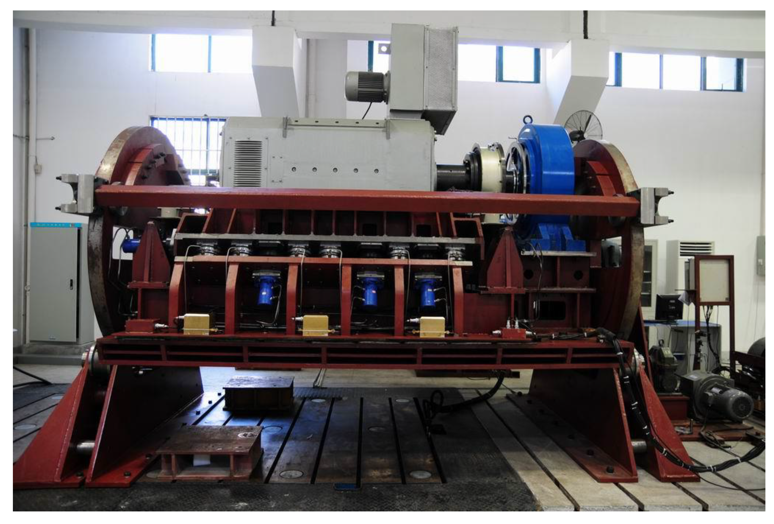
Figure 2 shows a photograph of an air vibration isolation system prototype and its test rig. To further enhance the alignment stability and vibration damping effects of air vibration isolation devices on ships’ main engines when the ship is tilted or swinging, Xu et al. analyzed the dynamic characteristic of the force transmission of an air vibration isolation device, and they noted that since the natural frequency of the air vibration isolator was lower than that of conventional rubber vibration isolators, its vibration isolation performance was far superior to that of rubber vibration isolation systems [
11]. He et al. [
10] established an analytical model for the alignment deviation of a main engine and analyzed the factors that affected the stability of the device. They found that for the design of the main engine air vibration isolation device, the location of the isolators needed to be as low as possible. Sun [
12] analyzed the effects of the stiffness, position, and angle of the air springs on the alignment stability and carried out the optimization design of the vibration reducing parameters of an air vibration isolation device using genetic algorithms. Compared to a horizontally positioned vibration isolation system, the optimization results not only improved the alignment stability of the device, but also reduced its natural frequency. The above research can play a guiding role in the design of a main engine air vibration isolation device, but the main emphasis is placed on the alignment stability of the device when the hull is tilted.
At present, the air vibration isolation devices for main engines are mostly installed using the inclined support method, and many researchers have studied this type of support. Crede has analyzed inclined isolation devices with a symmetric layout to obtain the position of the elastic axis and the vibration decoupling condition [
13]. The analysis shows that the vibration could be decoupled by judiciously configuring the structural parameters. Yan studied flat-mounted, radially mounted, converging-mounted, and inclined vibration isolation systems and found that the inclined configuration could not only reduce the center of gravity of the system, but also achieve vibration decoupling and ensure a higher transverse stiffness and roll flexibility by properly laying out the isolators [
14]. Wang et al. [
15] used the ratio of the difference between the two natural coupling frequencies of an inclined vibration isolation system and the vertical natural frequency of a horizontal vibration isolation system as the evaluation parameters to study the effects of the aspect ratio of the equipment, the inclination angle, and the ratio of the horizontal and vertical stiffnesses on the vibration isolation performance of the isolation system with inclined mounts. They further optimized the design and derived the matching relationship between the aspect ratio of the equipment, the stiffness ratio of the isolators, and the inclination angle to produce the optimal vibration isolation effect. Chen et al. [
16] studied the coupled lateral-roll vibration characteristics and the decoupling characteristics of an inclined vibration isolation system, and they showed that the transfer of the vibration energy could be substantially reduced by decoupling the lateral-roll vibration. The above investigations have shown that for power systems with a large excitation force in the roll direction, such as the main engines on a ship [
17], it is important to decouple the vibration isolation systems and to obtain the independent roll vibration when the inclined arrangement is adopted.
In engineering practice, the stability calculation of the vibration isolation device of a ship’s main engine often involves the use of the maximum swing or tilt angle to calculate the static response [
18]. The reasons for this are that: (1) A ship usually reaches the maximum swing period when it reaches the maximum swing angle. This rocking process can be regarded as a quasi-static process, which is equivalent to a tilted operating condition. (2) When a ship reaches its maximum rocking frequency, it usually reaches its smallest rocking amplitude. As a result, its impact on the stability of the vibration isolation device is much less than that of the large amplitude static swing. (3) A ship’s highest swing frequency is less than 0.5 Hz, which will not cause resonance of the vibration isolation device, and which has a small effect on the stability. The main effects of the main engine output torque on the stability of the vibration isolation device are: (1) The static displacement of the main engine caused by the DC component of the reaction of the output torque, and (2) The dynamic displacement of the main engine caused by the alternating torque reaction. Since the DC component of the output torque is much larger than its AC component, the fluctuating displacement caused by the AC component is relatively small, so in the design of the air vibration isolation device of the main engine, one usually considers only the static displacement change of the vibration isolation device caused by the DC component [
9].
In previous studies, since the tilt or swing of a hull has a much greater effect on the stability of a main engine air vibration isolation device when compared with the output torque reaction of the main engine, in the design of a vibration isolation device, the main concern is to eliminate the adverse effects of the tilt or swing of a hull [
10,
11,
12]. However, in the development of a propulsion system, some ship propulsion systems have adopted low-speed, high-power-density main engines [
19]. The power of the main engine increases by more than ten times, but the volume and weight change minimally, and the deviation in alignment generated by the torque reaction in the continued use of the inclined air vibration system will also increase by ten times or more. This increases the mechanical noise of the axle system and jeopardizes the safe operation of the system. Additionally, in terms of the alignment control of the main engine, because of the strong coupling between the components of the alignment control, the deviation in alignment generated by the torque reaction increases the conflict between the control targets and lowers the controllability of the main engine alignment [
20,
21]. Since the alignment control device adopts fuzzy control or pulse control [
22,
23], the alignment deviation caused by the reaction torque increases the adjustment amount or the number of adjustments of the air spring pressure required in the alignment control process, hence degrading the performance of the alignment control device. Therefore, unlike previous studies in which the main consideration has been the alignment stability of the device when the hull is tilted or swinging, in designing the alignment stability of the air vibration isolation devices for high power density main engines, emphasis should be placed on the effect of the output torque reaction.
In this research, we analyzed the alignment deviation generated by the output torque reaction and the decoupling condition of the system vibration by establishing a mechanical model of the air vibration isolation system. We proposed a dual-direction support for the air vibration isolators of a main engine and an optimized design method for the dual-direction support air vibration isolation device. The results showed that the dual-directional support air vibration isolation device and its optimized design method played an important role in eliminating the adverse effects of the output torque reaction on the main engine alignment stability, improving the alignment stability of the device under operating conditions with tilt or oscillation, improving vibration isolation performance and maintaining good alignment stability in the event of the failure of a single vertical support air spring.
2. Mechanical Model of Air Vibration Isolation System
Figure 3 shows a schematic diagram of a certain type of marine main engine air vibration isolation system. Taking the center of gravity of the main engine as the origin of the coordinate and the output shaft of the motor as the positive y-direction, we established a global coordinate system that coincided with the centered state of the main engine, as shown in
Figure 3. The air vibration isolators were positioned symmetrically with respect to the
yoz plane and the
xoz plane, and they were located at the same height.
The main engine and the foundation were treated as rigid bodies, and each air vibration isolator was treated as a linear spring. The system could then be expressed with the dynamics equation [
24]:
where
is the mass matrix of the main engine,
is the displacement of the main engine center of gravity in the direction of the
x,
y, and
z coordinates as well as the angle of rotation of the main engine around the
x,
y, and
z axes,
is the global stiffness matrix of the system formed by the stiffness matrix of the isolators and the elastic coupler after a coordinate transformation and
is a complex stiffness matrix when considering the damping, and
is the external force on the system.
By treating the effects of the external disturbance as a static process, one could obtain the displacement response of the main engine and the alignment of the main engine:
where
and
represents the position change matrix of the coupler.
Unless a vibration isolator is specifically designed to have a larger angular stiffness, the angular stiffness of the air vibration isolator can generally be ignored [
25] and the stiffness of the coupler can be ignored. Since the air vibration isolators were located at the same height, the global stiffness matrix was:
where
Here, , , are the coordinates of the ith air spring in the global coordinate system, , , , are the stiffness of the ith air spring in the directions of the global coordinate, , , are the lateral, lateral, and vertical stiffness of the ith air spring, θ is the inclination angle of the air vibration isolator, and is the sign function of , which was positive when was greater than zero and negative when was less than zero. Since the air spring was deployed symmetrically with respect to the yoz plane, and had equal magnitudes but opposite signs with respect to the yoz plane, while had a unified sign. Since appeared as a product form in , the coupling stiffnesses of the air spring in the directions of the coordinate system were not ignored in and .
The relationship of the load capacity of the air vibration isolator with the pressure and the effective area was [
6]:
In the formula,
P is the gauge pressure of the gas in the air spring, and
Se is the effective load-bearing area of the air vibration isolator. When the air spring was used at a constant height, the effective bearing area did not change. When the main engine was supported by multiple air springs, its load distribution was a statically indeterminate problem. In this research, the loads were distributed according to the principle of uniform distribution and optimized using the mean square error of the pressures in the different air springs as the objective function [
9,
26], as shown in Equation (7):
Here, is the pressure of each air spring, is the average pressure of n air springs, and lb and ub are the allowable lower limit and upper limit of the air spring pressure, respectively.
The general calculation model for the vertical stiffness of the air vibration isolator was [
6]:
where
is the atmospheric pressure,
is the air spring volume,
is the variable index of the gas change process, and
is the vertical deformation of the air spring.
In this research, the stiffness of the air vibration isolator was calculated according to an air vibration isolator stiffness recognition model based on the experimental data:
Here, and are the vertical and horizontal stiffness model parameter vectors to be recognized.
By combining Equations (2)–(5), we obtained the changes of the alignment state with the reaction of the output torque:
Here,
is the reaction of the output torque and
is the vertical coordinate of the coupler. Similarly, one could obtain the alignment state changes for the heeling and trimming conditions:
where
and
are the lateral and vertical forces on the main engine when the hull was heeled,
and
are the longitudinal and vertical forces on the main engine when the hull was trimmed.
Equation (4) shows that there were independent vertical and yaw vibrations, coupled transverse-roll vibrations, and longitudinal-pitch vibrations. When the transverse-roll coupling stiffness was zero, the main elastic axis of the system passed through the center of gravity and the decoupling condition was given by:
Similarly, the decoupling condition for the longitudinal-pitch vibration was:
4. Calculation Example Analysis
We used the design optimization of a dual-direction support of an air vibration isolation device for a specific high-power-density main engine as an example of the analysis. Based on the number of air springs limited by the dimensions of the installation space and the size of the air spring, and the number of air springs required by the weight of the main engine and the rated load capacity of the air spring, and further considering the fact that the horizontal support air springs were not under a load, we made the preliminary choice of JYQN-6000 air springs as vertical support air springs and JYQN-5000 air springs as horizontal support air springs to ensure the effectiveness of the vibration isolation device. The parameters of the main engine and the isolators are listed in
Table 1. The support modes were the inclined support mode and the dual-directional support mode proposed in this paper. The parameters of the air vibration isolation devices are listed in
Table 2.
The number of air springs used to assume the vertical load in the dual-direction support was based on the average load-bearing capacity of the air springs, and the number of horizontal support air springs was based on the reliability requirement of the control device. In total, six horizontal support air springs were installed at the four corners and on the two sides of the main engine. It could be ensured that the vertical coordinate of the coupler was at zero by properly adjusting the positions and weight of the counterweights of the cooling air fans to change the center of mass of the main engine, including the counterweights.
4.1. Alignment Stability
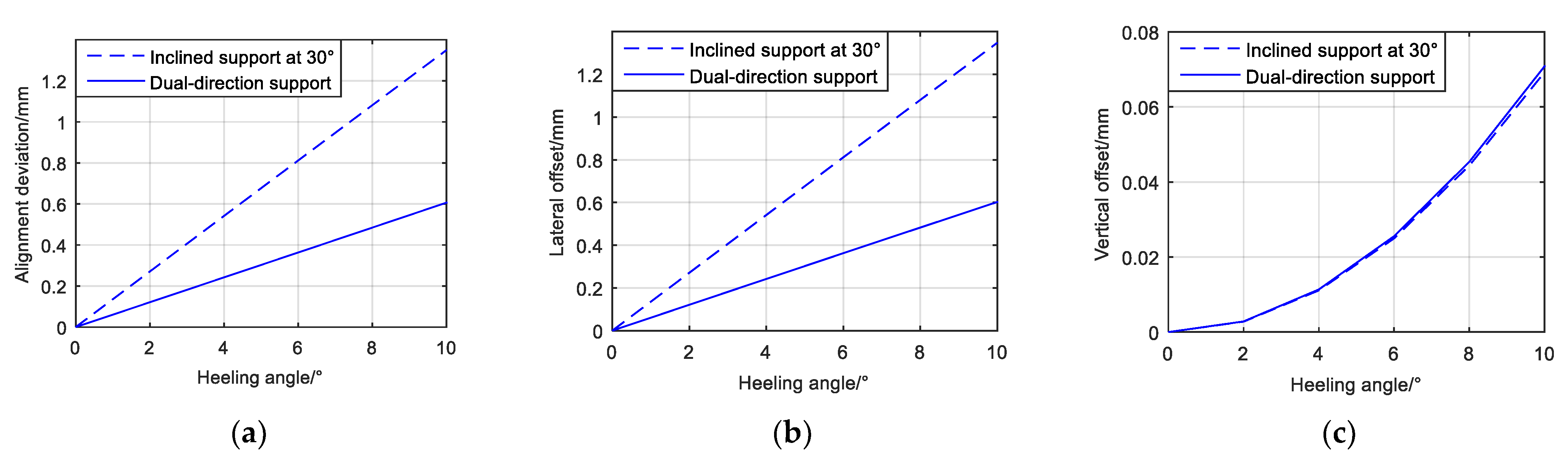
Using the horizontal–vertical stiffness ratio of the air spring and the operating pressure of the horizontal air spring as design parameters, we applied the design optimization method described in
Section 2 and we obtained a horizontal–vertical stiffness ratio of 2.4 for the vertical support air springs and a horizontal–vertical stiffness ratio of 1.0 for the horizontal support air springs; the obtained operating air pressure for the horizontal support air springs was 0.50 MPa. The displacement of the main engine output terminal with the disturbance of the output torque reaction and a listed hull in the stealth operating condition is shown in
Figure 5,
Figure 6 and
Figure 7.
Hence, unlike the inclined support of the air vibration isolator, when the dual-direction structure was adopted and the vertical mounting distance and the vertical coordinate of the coupler were both 0, the output terminal of the main engine with the reaction of the output torque no longer generated the alignment deviation, which eliminated the adverse effect of the output torque on the alignment performance of the main engine.
With the optimization method proposed here, although the vertical offset of the main engine when the ship heeled 10° went up by 2.27%, the lateral offset was reduced by 55.32%, resulting in a 55.07% reduction in alignment deviation. The longitudinal offset of the main engine when the ship trimmed 10° was reduced by 39.13%, the vertical offset was reduced by 90.28%, resulting in a 48.47% reduction in alignment deviation. Therefore, the alignment performance of the device was improved on a tilted or swaying ship.
4.2. Aligning Stability under Different Load Distribution Modes
In extreme cases, individual air springs can be incapacitated by severe malfunctions. The horizontal support air springs do not bear the weight of the main engine. Therefore, when one horizontal support air spring fails, the force balance of the main engine can be ensured by unloading the air spring at the symmetrical position of the yoz plane. However, the vertical support air springs are used to carry the weight of the main engine, so in the event of failures of the vertical support air springs, the load of the main engine needs to be redistributed among the remaining air springs to maintain the operation of the vibration isolation system. Therefore, it is necessary to study the influence of the change in the vertical support air springs’ load distribution on the alignment stability of the vibration isolation system. This paper studies the alignment stability of the vibration isolation device when a single vertical support air spring fails.
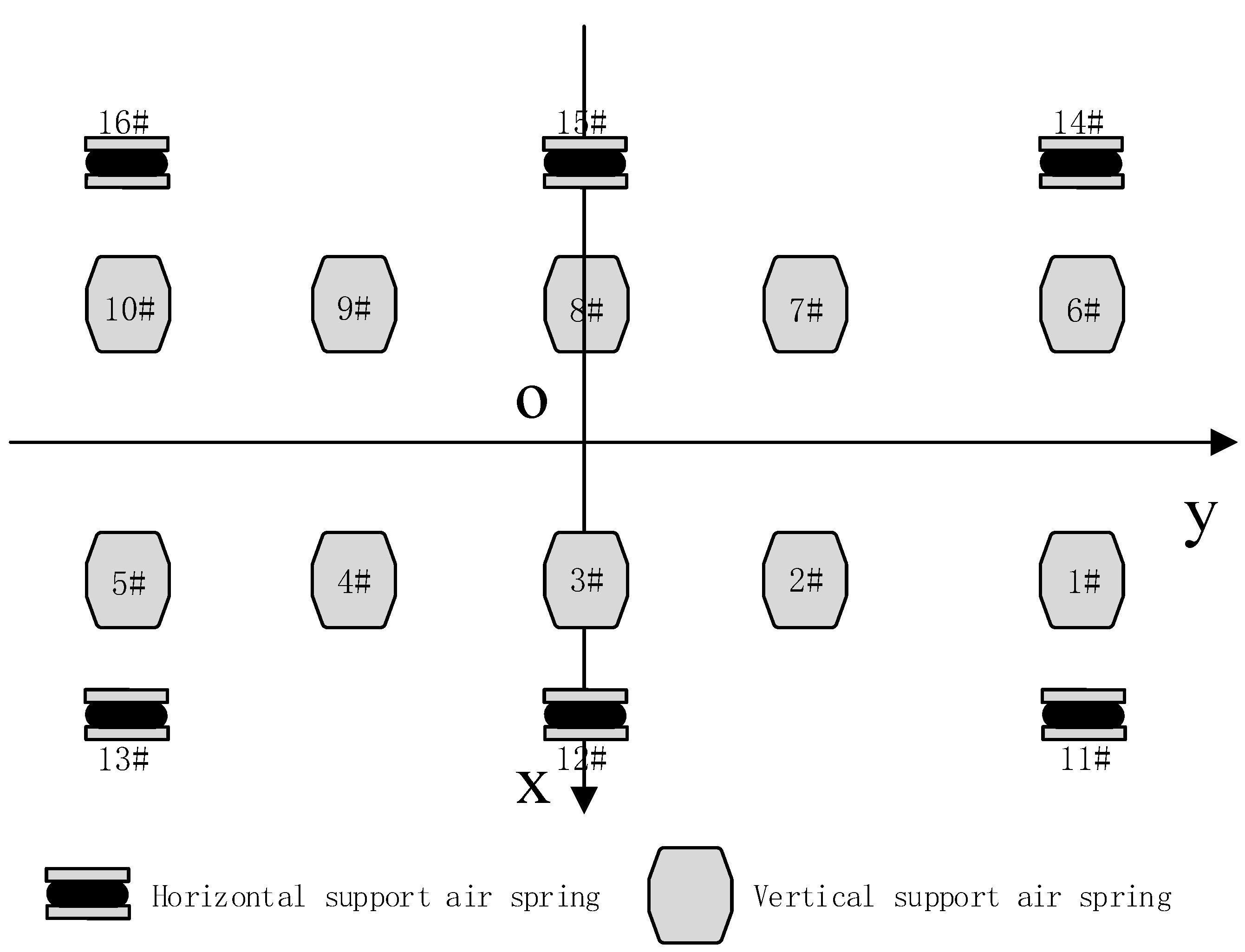
As the air springs are symmetrically arranged on the plane
xoz and
yoz, only the influence of first, second or third air spring failure on the stability of the vibration isolation device is studied. It is assumed that the air spring number is shown in
Figure 4 and the load of the air springs is distributed according to the modes shown in
Table 3. Modes 1–4 represent all air springs in normal operation, and in first, second, or third air spring failure, respectively.
Table 4,
Table 5 and
Table 6, respectively, show the alignment stability of the air vibration isolation device when the hull was heeled, trimmed and with the reaction of the output torque under the above four load distribution modes.
By comparing the alignment stability of any air spring failure with that of the vibration isolation device in normal mode, it can be seen that the alignment stability of the motor is basically the same under the heeling and trimming conditions when an air spring failure occurs. However, the motor’s alignment stability becomes very different with the reaction of the output torque. Under the condition of maximum output torque, the displacement of the main engine output terminal is 0 mm when the third air spring fails, 0.556 mm when the second air spring fails, and 1.431 mm when the first air spring fails, which is still less than the alignment deviation when the air springs are supported obliquely under normal working conditions.
This indicates that a single vertical air spring failure mainly affects the stability of the main engine under the reaction of output torque, especially the air springs arranged in the corner, while the air springs arranged in the middle have no effect. This is caused by the fact that when a single air spring fails, the air spring and its load distribution are no longer symmetric about the plane xoz and yoz, which affects the form of the system stiffness matrix in Equation (4).
4.3. Vibration Isolation Performance
The natural frequencies of the device in the inclined support configuration and the optimized dual-direction support configuration are shown in
Table 7. Since the vibrations transmitted to the base of the machinery were mainly the bending waves generated by the excitation force perpendicular to the base [
31], we evaluated the vibration isolation performance of the dual-direction support of the air vibration isolation device based on the transmission characteristics of the vertical and horizontal forces. According to the measured data, the damping ratio of the air spring used in the program was 0.06. With the action of the dynamic excitation forces and in the Z-direction and the X-direction, respectively, and the dynamic torque around the
Y-axis, the frequency response curves for the horizontal and vertical forces were as shown in the curves in
Figure 8.
Hence, when the dual-direction structure was adopted and the vertical mounting distance and the vertical coordinate of the coupler were both 0, the vibrations of the device in the various directions were decoupled, which was beneficial to the improvement of the vibration isolation performance of the device. The dynamic response results showed that air vibration isolation devices with dual-directional support could reduce the number of peaks in the transmitted force by decoupling the vibration of the system. With the optimized design, the natural frequency of the device could be further reduced to improve the vibration isolation at low frequencies.
5. Conclusions
Simulation experiments of alignment stability, aligning stability under different load distribution modes and vibration isolation performance were carried out for the dual-direction support design for the air vibration isolators of a main engine and the optimized design method for the dual-direction support air vibration isolation device proposed in this paper. In this regard, the main conclusions are summarized as follows:
(1) This design avoids the effects of the output torque reaction on the alignment of the device. That means the reaction torque no longer produced alignment deviation, which is important for the application of airbag vibration isolation device to high power density main engines.
(2)The optimized design not only improved the alignment stability of the main engine with the ship operating in tilted or swinging conditions compared to vibration isolation devices supported by inclined air springs, but also could maintain the good alignment stability of the device when a single vertical support air spring failed. It means the design can improve the alignment stability of the device under various disturbance conditions and keep the propulsion system safe even if a single vertical support air spring fails. Additionally, special attention should be paid to the safe working condition of the air springs located in the corner of the application because they have a greater effect on the stability of the main engine under the reaction of the output torque.
(3) The various terms of vibration of the dual-direction support air vibration isolation device become decoupled to reduce the number of peaks in the transmitted force, which facilitates vibration control. Additionally, the optimized design enhanced the vibration isolation performance, which served as an important reference for the design of the air vibration isolation devices of high power density main engines.
(4) As the reaction torque no longer produced alignment deviation and the coupling of the various control targets was reduced, the conflicts between the control targets were reduced, which was beneficial for improving the controllability of the alignment and the control performance of the device.


