Abstract
Bistable energy harvesters have been extensively studied. However, theoretical research on the dynamics of bistable energy harvesters based on asymmetric bistable composite laminated plate and shell structures has not been conducted. In this paper, a theoretical model on the dynamics of an energy harvester based on an asymmetric bistable composite laminated shell is established. The dynamic snap-through, the nonlinear vibrations and the voltage output with two potential wells of the bistable energy harvester are studied. The influence of the amplitude and the frequency for the base excitation on the bistable energy harvester is studied. When the frequency for the base excitation with a suitable amplitude in the frequency sweeping is located in a specific range or the amplitude for the base excitation with a suitable frequency in the amplitude sweeping is located in a specific range, the large-amplitude dynamic snap-through, nonlinear vibrations and voltage output with two potential wells can be found to occur. The amplitude and the frequency for the base excitation interact on each other for the specific amplitude or frequency range which migrates due to the softening nonlinearity. The vibration in the process of the dynamic snap-through behaves as the chaotic vibration. The nonlinear vibrations of the bistable system behave as the periodic vibration, the quasi-periodic vibration and the chaotic vibration. This study provides a theoretical reference for the design of energy harvesters based on asymmetric bistable composite laminated plate and shell structures.
1. Introduction
Bistable composite laminated plate and shell structures have two equilibrium configurations, so the large-amplitude dynamic snap-through and nonlinear vibrations may occur in dynamic environments, which greatly promotes the development of energy harvesters. The conventional energy harvesters integrated with bistable composite laminated plate and shell structures are designed as many kinds of bistable energy harvesters. Compared with conventional energy harvesters, bistable energy harvesters produce more strain and thus improve the power generation efficiency due to the large-amplitude dynamic snap-through and nonlinear vibrations with two potential wells. In fact, there have been several types of bistable energy harvesters based on different bistable structures. At present, the bistability of bistable energy harvesters can be realized by many ways. Specific boundary conditions and external forces can make structures buckle and thus obtain bistability [1,2,3]. In the manufacturing process, structures can realize bistability by applying the prestress to the materials [4,5,6,7]. When the plastic deformation or the inelastic deformation is applied to the materials, two or more stable equilibrium configurations can be obtained. The plastic deformation or the inelastic deformation is usually defined as Gaussian curvature effect [8,9,10,11,12,13]. The residual thermal stress formed in the curing process of asymmetric composite laminates can lead to two stable equilibrium configurations [14,15,16,17,18,19,20,21]. The integration of structures and bistable composite laminates can make the structures have two stable equilibrium configurations [22,23,24]. In this paper, an asymmetric bistable composite laminated shell for an energy harvester is adopted. The bistable shell is formed by an asymmetric composite laminated plate containing residual thermal stress which is naturally formed during curing. The greatest advantage of the asymmetric bistable composite laminated shell is that it is naturally formed by an asymmetric composite laminated plate through cooling from high temperature to room temperature without manual operations.
So far, some research on many different kinds of bistable energy harvesters has been carried out. Clamped–clamped buckled beams and cantilever beams for bistable energy harvesters were studied [25,26,27]. The magnetic forces were deployed to generate bistability [28,29]. Arrieta et al. [30] designed a nonlinear broadband energy harvester making use of a bistable plate and its nonlinearity. Lee and Inman [31] designed an asymmetric bistable composite laminated plate and shell structure by using two orthogonal MFCs (macro-fiber composites) for broadband energy harvesting. Syta et al. [32] utilized cross-well dynamics with snap-through of an asymmetric bistable composite laminated plate to enhance power generation capacity. Emam et al. [33] studied the snap-through and the period-doubling bifurcation of a bistable energy harvester based on an antisymmetric bistable composite laminated plate. Emam and Inman [34] summarized the developments and the principles of many different kinds of bistable energy harvesters. Pellegrini et al. [35] utilized the duffing oscillator to describe dynamics of all kinds of bistable energy harvesters. Lu et al. [36] performed research on energy harvesting during the passive vibration isolation. Single-well vibrations and the snap-through of bistable energy harvesters were also exhibited [37].
Above all, although there has been much research on many different kinds of bistable energy harvesters, the research on energy harvesters based on asymmetric bistable composite laminated plate and shell structures were focused on experiments. As the asymmetric bistable composite laminated plate and shell structures are naturally formed by asymmetric composite laminates through cooling from high temperature to room temperature without manual operations, it is very necessary and meaningful to study energy harvesters based on asymmetric bistable composite laminated plate and shell structures theoretically.
In this paper, a dynamic model of an energy harvester based on an asymmetric bistable composite laminated shell is established. The influence of the base excitation amplitude and frequency on the bistable energy harvester is studied. The frequency sweeping with a constant amplitude and the amplitude sweeping with a constant frequency are carried out respectively. The dynamic snap-through, the nonlinear vibrations and the voltage output with two potential wells of the bistable energy harvester are given. When the frequency for the base excitation with a suitable amplitude is located in a specific range in the frequency sweeping or the amplitude for the base excitation with a suitable frequency is located in a specific range in the amplitude sweeping, the large-amplitude dynamic snap-through, nonlinear vibrations and voltage output with two potential wells can be found to occur. That is to say, deploying only one parameter amplitude or frequency for the base excitation cannot maximize the optimization of the bistable energy harvester. When the amplitude and the frequency for the base excitation jointly achieve the maximum optimization, the large-amplitude dynamic snap-through and voltage output can be realized in a very ideal amplitude or frequency range for the base excitation.
2. Dynamic Model
In order to determine the two stable equilibrium configurations formed after curing of the asymmetric composite laminated plate shown in Figure 1, the displacement field can be written based on the classical plate theory in Ref. [38] as follows
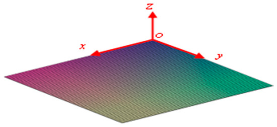
Figure 1.
The asymmetric composite laminated plate [0/0/0/0/90/90/90/90] before curing.
Based on the von Kármán′s large deformation theory in Ref. [38], the nonlinear strain-displacement relationship can be determined:
The constitutive relation of the asymmetric composite laminated plate is
where ΔΤ denotes the difference between the room temperature and the manufacturing temperature, and
where
Based on Equations (1)–(8), the potential energy of the asymmetric composite laminated plate can be determined
where the VLam denotes the volume of the asymmetric composite laminated plate.
In order to determine the static equilibrium configurations, u0, v0 and w0 in Equations (1)–(5) are replaced by static displacements , and .
According to Refs. [38,39], the static displacement field can be set as
The principle of minimum potential energy can be expressed in the following form
where the ULam1 denotes the potential energy of the asymmetric composite laminated plate, and , and .
Setting the absolute value of the temperature difference |ΔΤ| as the control parameter and solving f1, f2 and f3 by Equations (9)–(13), the static bifurcation diagram Figure 2 can be graphically presented as below.
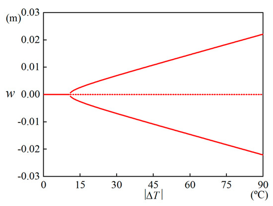
Figure 2.
The static bifurcation diagram for the asymmetric composite laminated plate.
When ΔΤ is set to −90 °C, the asymmetric composite laminated plate generates two stable equilibrium states with large deformation. However, when ΔΤ is too small, the deformation is not obvious, and when ΔΤ is too large, the manufacturing cost is increased.
Making ΔΤ = −90 °C, , and corresponding to the lower stable equilibrium configuration and , and corresponding to the upper stable equilibrium configuration can be determined shown in Figure 3.
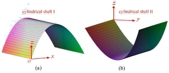
Figure 3.
The two stable cylindrical shells after curing, (a) the cylindrical Shell I, (b) the cylindrical Shell II.
Compared to a simple piezoelectric layer, the energy approach based on the MFC is similar. Since the two stable states of the bistable structure behave as cylindrical shells, the simple piezoelectric layer may significantly reduce the curvature and weaken the bistability of the bistable structure, while the MFC can guarantee the bistability of the bistable structure. Moreover, the MFC can be used to actuate the snap-through, which will be introduced in the next stage.
Since the MFC is to be attached to the surface of the shell, the plate model above must be transformed into a shell model.
Due to the stiffness of the MFC itself, new deformations can occur in the process of attaching the MFC to the surface of the bistable shell, which produces new equilibrium positions.
Setting , and as initial equilibrium positions and combining with Equations (1)–(3), the displacement field of the bistable shell can be obtained:
The new nonlinear strain-displacement relationship can be determined
To determine the new equilibrium positions, the potential energy must be recalculated, and the principle of minimum potential energy must be carried out again.
The constitutive relationship for the shell of the MFC–bistable composite laminated shell structure is
where ΔΤ denotes the difference between the room temperature and the manufacturing temperature, and
where
Equations (6), (7), (20) and (21) are the same in form but different in content. Equations (6) and (7) denote the plate, while Equations (20) and (21) denote the shell.
The constitutive relationship for the MFC of the MFC–bistable composite laminated shell structure is
Based on Equations (14)–(22), the potential energy of the bistable shell in the structure is recalculated as
Based on Equations (14)–(19) and (23), the potential energy of the MFC in the structure is
The total potential energy of the MFC–bistable composite laminated shell structure is
The principle of minimum potential energy is re-expressed as follows
By solving Equation (27), the deformations , and in the process of attaching the MFC to the surface of the bistable shell can be determined.
The new equilibrium positions can be expressed
Finally, the energy harvester based on the asymmetric bistable composite laminated shell is determined shown in Figure 4.
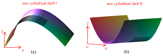
Figure 4.
The two new stable cylindrical shells with a piezoelectric patch on the surface, (a) the cylindrical Shell I, (b) the cylindrical Shell II.
In order to establish the dynamic model shown in Figure 5 for the bistable energy harvester, the displacement field must be written as follows
where Y is the base excitation.
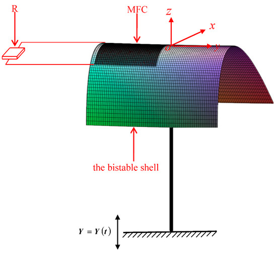
Figure 5.
The dynamic model for the bistable energy harvester based on the asymmetric bistable composite laminated shell.
The nonlinear strain-displacement relationship of the MFC–bistable shell structure is rewritten as
Based on Equations (20)–(22) and (28)–(36), the potential energy of the bistable shell in the structure is redefined as
Based on Equations (23) and (28)–(36), the potential energy of the MFC in the structure is the sum of its own strain energy and the electric potential energy after energization.
The kinetic energy of the bistable shell in the structure is defined as
The kinetic energy of the MFC in the structure is defined as
The work performed by the electric field in the direction of potential shift is
The potential shift Dz is homogenized in the thickness direction
The electric charge quantity is calculated
An energy balance is introduced
where V(t) is the voltage and Q(t) is the electric quantity.
The work performed by external forces is
where c is the damping coefficient.
The relationship between the current and the voltage is as follows
where R is the external electrical resistance, and I(t) is the current.
The Hamilton’s principle according to Ref. [38] is given as
where
In order to study the dynamic snap-through, the nonlinear vibrations and the voltage output with two potential wells of the bistable energy harvester, the dynamic displacements according to Ref. [39] are set as
Substituting Equations (37)–(46) and (49)–(51) into Equation (47), integrating on plane (x∈[−Lx, Lx] and y∈[−Ly, Ly]), selecting the first three degrees of freedom and introducing dimensionless parameters,
dimensionless ordinary differential equations can be obtained
The coefficients in Equations (53)–(55) can be determined by material properties shown in Table 1 and Table 2 and step-by-step numerical calculations from Equation (1) to Equation (55). Based on Ref. [40], the Table 1 and Table 2 take the following form.

Table 1.
Material properties of the bistable asymmetric composite laminated shell.
Table 2.
Material properties of the MFC.
3. Numerical Simulation
In order to study the dynamic snap-through, the nonlinear vibrations and the voltage output with two potential wells of the energy harvester based on the asymmetric bistable composite laminated shell, the Runge–Kutta method is adopted to solve Equations (53)–(55). The bifurcation diagram, the time-history graph, the Poincaré map, the amplitude-frequency curve and the spectrum diagram are demonstrated. Dimensionless symbols are omitted in Equations (53)–(55) for convenience. The influence of the base excitation amplitude f and frequency Ω on the bistable energy harvester is studied.
3.1. Dynamic Snap-Through and Nonlinear Vibrations
The time-history diagrams, the spectrum diagrams and the Poincaré maps are graphically presented in Figure 6, Figure 7, Figure 8, Figure 9, Figure 10 and Figure 11, which represent different vibrations based on different operating conditions. When the insufficient energy is applied, the vibration of the system revolves around either the upper stable state or the lower stable state shown in Figure 6, while when the sufficient energy is applied, the system vibrates between the two stable states, which denotes the dynamic snap-through shown in Figure 7 and Figure 11. The dynamic snap-through is elaborated in Figure 7 and Figure 11 delivering the vibrations around the two stable states respectively and the dynamic snap-through between the two stable states. The vibration in the process of the dynamic snap-through behaves as the chaotic vibration which is the nonlinear vibration with two potential wells due to the two stable equilibrium positions. The nonlinear vibrations of the bistable system in the whole process behave as the periodic vibration, the quasi-periodic vibration and the chaotic vibration based on the Poincaré maps shown in Figure 9, Figure 10 and Figure 11. Similarly, the vibrations of the bistable system can be detected by the spectrum diagrams. The vibration of the system revolves around either the upper stable state or the lower stable state behaves as the periodic vibration or the quasi-periodic vibration according to the spectrum diagrams in Figure 6b,c, where the response of the system is excited only at a certain frequency. Based on the spectrum diagram in Figure 7b, where the responses of the system are excited in a broadband, the vibration in the process of the dynamic snap-through behaves as the chaotic vibration.
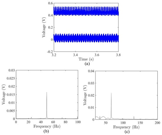
Figure 6.
The voltage outputs around the two stable states respectively, (a) the time-history graphs around the two stable states respectively, (b) the spectrum diagram for the lower stable state, (c) the spectrum diagram for the upper stable state.
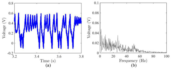
Figure 7.
The dynamic snap-through for the voltage output, (a) the time-history graph, (b) the spectrum diagram.
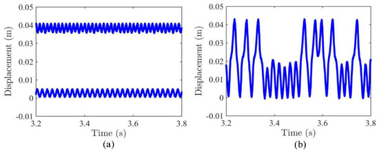
Figure 8.
The vibrations of the asymmetric bistable composite laminated shell, (a) the vibrations around the two stable states respectively, (b) the dynamic snap-through between the two stable states.
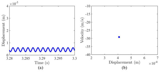
Figure 9.
The periodic vibration, (a) the time-history graph, (b) the Poincaré map.
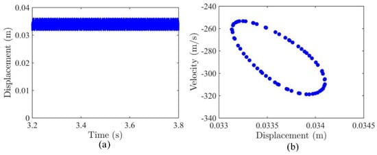
Figure 10.
The quasi-periodic vibration, (a) the time-history graph, (b) the Poincaré map.
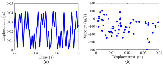
Figure 11.
The dynamic snap-through and chaotic vibration, (a) the time-history graph, (b) the Poincaré map.
3.2. Frequency Sweeping
The Runge–Kutta method is adopted to solve the dimensionless Equations (53)–(55). Dimensionless symbols are omitted in Equations (53)–(55) for convenience. A series of bifurcation diagrams can be obtained shown in Figure 12, Figure 13 and Figure 14 by sweeping frequency while keeping the amplitude constant. Figure 12 shows the bifurcation diagrams for displacement w and voltage output V by sweeping frequency when f = 0.2. Figure 13 shows the bifurcation diagrams for displacement w and voltage output V by sweeping frequency when f = 0.3. Figure 14 shows the bifurcation diagrams for displacement w and voltage output V by sweeping frequency when f = 0.6.
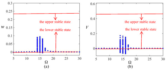
Figure 12.
The bifurcation diagrams for displacement w and voltage V via the base excitation frequency Ω when amplitude f = 0.2, (a) the dynamic displacement, (b) the voltage output of harvester.
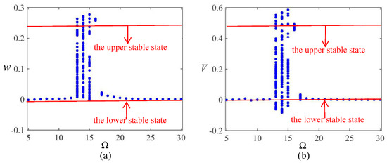
Figure 13.
The bifurcation diagram for displacement w and voltage V via the base excitation frequency Ω when amplitude f = 0.3, (a) the dynamic displacement, (b) the voltage output of harvester.
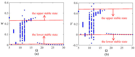
Figure 14.
The bifurcation diagram for displacement w and voltage V via the base excitation frequency Ω when amplitude f = 0.6, (a) the dynamic displacement, (b) the voltage output of harvester.
The bistable energy harvester has two equilibrium positions shown in Figure 12, Figure 13 and Figure 14 due to the two stable equilibrium states of the asymmetric bistable composite laminated shell. As shown in Figure 12, Figure 13 and Figure 14, when the frequency for the base excitation with an appropriate amplitude is located in a particular range, the bistable system is found to vibrate between the two equilibrium positions, denoting the dynamic snap-through, while when the frequency is outside this particular range, the bistable system is found to vibrate around an equilibrium position.
Deploying an amplitude of 0.3, the frequency range for the base excitation, where the bistable system vibrates violently between the two equilibrium positions, denoting the dynamic snap-through, is 13~15 shown in Figure 13. Nevertheless, when the amplitude varies from 0.3 to 0.6, the frequency range where the dynamic snap-through can be found to occur migrates from 13~15 to 10~12 shown in Figure 14. The major reason why the frequency range migrates with the increase of the amplitude is the softening nonlinearity of the bistable system. The softening characteristics are detected based on the amplitude-frequency curve shown in Figure 15. The bistable system is a softening nonlinear system due to its negative stiffness. When the excitation amplitude increases gradually, the softening nonlinearity of the bistable system is enhanced during frequency sweeping, leading to the migration of the frequency range for the dynamic snap-through.
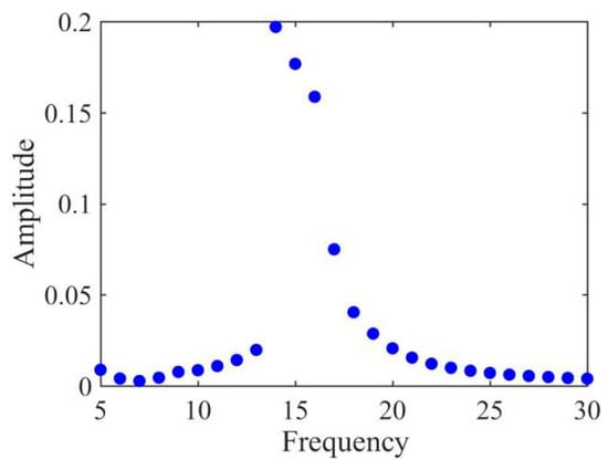
Figure 15.
The amplitude-frequency curve for the voltage output.
The voltage output can also be elucidated in Figure 12, Figure 13 and Figure 14. With an amplitude of 0.2, the small-amplitude voltage revolves round the upper equilibrium position during frequency sweeping shown in Figure 12, which is similar to that of conventional nonlinear energy harvesters with a single potential well. At an amplitude of 0.3, the bistability is exhibited in the process of frequency sweeping. Due to the two equilibrium positions, the voltage output of the bistable energy harvester behaves as the large-amplitude dynamic snap-through and nonlinear vibrations with two potential wells shown in Figure 13 and Figure 14. Comparing Figure 12 and Figure 13, the amplitude of the latter voltage is three times that of the former voltage. Due to the large-amplitude dynamic snap-through and nonlinear vibrations with two potential wells, the bistable energy harvester produces large strains and in turn generates large power.
3.3. Amplitude Sweeping
Analogy to the previous section, the Runge–Kutta method is adopted to solve the dimensionless Equations (53)–(55) and dimensionless symbols are omitted in Equations (53)–(55) for convenience. A series of bifurcation diagrams can be obtained shown in Figure 16, Figure 17, Figure 18, Figure 19 and Figure 20 by sweeping amplitude while keeping the frequency constant. When the amplitude for the base excitation with an appropriate frequency is located in a particular range shown in Figure 17, Figure 18 and Figure 19, the bistable system is found to vibrate between the two equilibrium positions, denoting the dynamic snap-through, while when the amplitude is outside this particular range, the bistable system is found to vibrate around an equilibrium position. During amplitude sweeping with the too small excitation frequency shown in Figure 16 and the too large excitation frequency shown in Figure 20, the bistable system is found to vibrate around an equilibrium position.
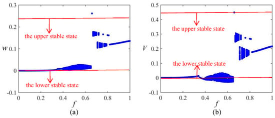
Figure 16.
The bifurcation diagram for displacement w and voltage V via the base excitation amplitude f when frequency Ω = 8, (a) the dynamic displacement, (b) the voltage output of harvester.
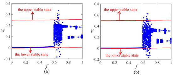
Figure 17.
The bifurcation diagram for displacement w and voltage V via the base excitation amplitude f when frequency Ω = 10, (a) the dynamic displacement, (b) the voltage output of harvester.
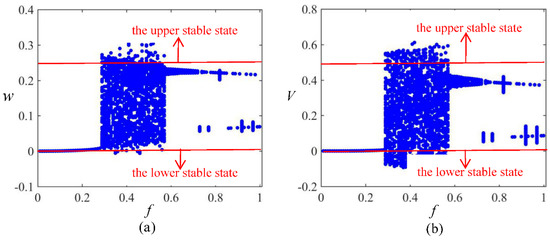
Figure 18.
The bifurcation diagram for displacement w and voltage V via the base excitation amplitude f when frequency Ω = 13, (a) the dynamic displacement, (b) the voltage output of harvester.
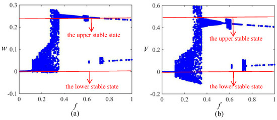
Figure 19.
The bifurcation diagram for displacement w and voltage V via the base excitation amplitude f when frequency Ω = 15, (a) the dynamic displacement, (b) the voltage output of harvester.
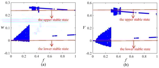
Figure 20.
The bifurcation diagram for displacement w and voltage V via the base excitation amplitude f when frequency Ω = 16, (a) the dynamic displacement, (b) the voltage output of harvester.
With a frequency of 8, the bistable system vibrates slightly around the lower equilibrium position during amplitude sweeping, which is similar to that of conventional nonlinear energy harvesters with a single potential well. With a slight increase in the frequency, a very narrow amplitude range for the base excitation, where the large-amplitude dynamic snap-through and nonlinear vibrations with two potential wells can be induced, is identified. As the frequency continues to increase, the amplitude range for the base excitation where the dynamic snap-through can be found to occur widens first, then narrows, and finally disappears.
Deploying a frequency of 10, the amplitude range for the base excitation, where the bistable system vibrates violently between the two equilibrium positions, denoting the dynamic snap-through, is 0.6~0.7 shown in Figure 17. Nevertheless, when the frequency varies from 10 to 13, the amplitude range where the dynamic snap-through can be found to occur migrates from 0.6~0.7 to 0.3~0.6 shown in Figure 18. Continuing to increase the frequency to 15, the amplitude range for the base excitation migrates to 0.25~0.35. The major reason why the amplitude range migrates with the increase of the frequency is the softening nonlinearity of the bistable system. The bistable system is a softening nonlinear system due to its negative stiffness. When the excitation frequency increases gradually, the softening nonlinearity of the bistable system is enhanced during amplitude sweeping, leading to the migration of the amplitude range for the dynamic snap-through.
The voltage output can also be elucidated in Figure 16, Figure 17, Figure 18, Figure 19 and Figure 20. With a frequency of 8, the small-amplitude voltage revolves round the upper equilibrium position during amplitude sweeping shown in Figure 16, which is similar to that of conventional nonlinear energy harvesters with a single potential well. At a frequency of 10, the bistability is exhibited in the process of amplitude sweeping shown in Figure 17. Due to the two equilibrium positions, the voltage output of the bistable energy harvester behaves as the large-amplitude dynamic snap-through and nonlinear vibrations with two potential wells shown in Figure 17, Figure 18 and Figure 19. Comparing Figure 19 and Figure 20, the amplitude of the former voltage is five times that of the latter voltage. Due to the large-amplitude dynamic snap-through and nonlinear vibrations with two potential wells, the bistable energy harvester produces large strains and in turn generates large power.
4. Conclusions
In this paper, the theoretical model on the dynamics of the energy harvester based on the asymmetric bistable composite laminated shell is established. The influence of the amplitude and the frequency for the base excitation on the bistable energy harvester is studied. The frequency sweeping with a constant amplitude and the amplitude sweeping with a constant frequency are carried out respectively.
When the frequency for the base excitation with a suitable amplitude is located in a specific range in the frequency sweeping or the amplitude for the base excitation with a suitable frequency is located in a specific range in the amplitude sweeping, the large-amplitude dynamic snap-through, nonlinear vibrations and voltage output with two potential wells can be found to occur. The amplitude and the frequency for the base excitation interact on each other for the specific frequency or amplitude range, that is to say, for the base excitation with different constant amplitudes in the frequency sweeping, the specific frequency ranges are different while for the base excitation with different constant frequencies in the amplitude sweeping, the specific frequency ranges are different.
The specific frequency or amplitude range for the base excitation, where the large-amplitude dynamic snap-through, nonlinear vibrations and voltage output with two potential wells can be found to occur, migrates due to the softening nonlinearity. The vibration in the process of the dynamic snap-through of the bistable system behaves as the chaotic vibration. The nonlinear vibrations of the bistable system behave as the periodic vibration, the quasi-periodic vibration and the chaotic vibration.
Author Contributions
Conceptualization, T.D. and X.C.; methodology, T.D.; software, T.D.; validation, T.D., X.C. and J.Z.; formal analysis, T.D.; investigation, T.D.; resources, T.D.; data curation, T.D.; writing—original draft preparation, T.D.; writing—review and editing, X.C.; visualization, T.D.; supervision, X.C. and J.Z.; project administration, X.C.; funding acquisition, X.C. All authors have read and agreed to the published version of the manuscript.
Funding
This research work was funded by Natural Science Foundation of Beijing Municipality (8202015), the Excellent Researcher Award Program from Ministry of Beijing (No. 2017000020124G005), the Fundamental Research Funds for Beijing Universities (No. X18253), Open Research Fund Pro-gram of Beijing Advanced Innovation Center for Future Urban Design (Grant No. UDC2017033022), Open Research Fund Program of Beijing Key Laboratory of Performance Guarantee on Urban Rail Transit Vehicles (No. 06080915001) and Beijing Shi Pei Project.
Institutional Review Board Statement
Not applicable.
Informed Consent Statement
Not applicable.
Data Availability Statement
The study did not report any data.
Acknowledgments
This research work was supported by Natural Science Foundation of Beijing Municipality (8202015), the Excellent Researcher Award Program from Ministry of Beijing (No. 2017000020124G005), the Fundamental Research Funds for Beijing Universities (No. X18253), Open Research Fund Program of Beijing Advanced Innovation Center for Future Urban Design (Grant No. UDC2017033022), Open Research Fund Program of Beijing Key Laboratory of Performance Guarantee on Urban Rail Transit Vehicles (No. 06080915001) and Beijing Shi Pei Project.
Conflicts of Interest
The authors declare no conflict of interest.
References
- Emam, S.A.; Nayfeh, A.H. On the nonlinear bynamics of a buckled beam subjected to a primary-resonance excitation. Nonlinear Dyn. 2004, 35, 1–17. [Google Scholar] [CrossRef]
- Abou-Rayan, A.M.; Nayfeh, A.H.; Mook, D.T. Nonlinear response of a parametrically excited buckled beam. Nonlinear Dyn. 1993, 4, 499–525. [Google Scholar] [CrossRef]
- Lacarbonara, W.; Nayfeh, A.H.; Kreider, W. Experimental validation of reduction methods for nonlinear vibrations of distributed-parameter systems: Analysis of a buckled beam. Nonlinear Dyn. 1998, 17, 95–117. [Google Scholar] [CrossRef]
- Daynes, S.; Potter, K.D.; Weaver, P.M. Bistable Prestressed Buckled Laminates. Compos. Sci. Technol. 2008, 68, 3431–3437. [Google Scholar] [CrossRef]
- Li, H.; Dai, F.; Weaver, P.M.; Du, S. Bistable hybrid symmetric laminates. Compos. Struct. 2014, 116, 782–792. [Google Scholar] [CrossRef]
- Daynes, S.; Nall, S.J.; Weaver, P.M.; Potter, K.D.; Margaris, P.; Mellor, P.H. Bistable composite flap for an airfoil. J. Aircr. 2010, 47, 334–338. [Google Scholar] [CrossRef]
- Daynes, S.; Weaver, P.M.; Trevarthen, J.A. A morphing composite air inlet with multiple stable shape. J. Intell. Mater. Syst. Struct. 2011, 22, 961–973. [Google Scholar] [CrossRef]
- Guest, S.D.; Pellegrino, S. Analytical models for bistable cylindrical shells. Proc. R. Soc. A 2006, 462, 839–854. [Google Scholar] [CrossRef]
- Seffen, K.A. ‘Morphing’ bistable orthotropic elliptical shallow shells. Proc. R. Soc. A 2007, 463, 67–83. [Google Scholar] [CrossRef]
- Brinkmeyer, A.; Santer, M.; Pirrera, A.; Weaver, P.M. Pseudo bistable self-actuated domes for morphing applications. Int. J. Solids Struct. 2012, 49, 1077–1087. [Google Scholar] [CrossRef] [Green Version]
- Brinkmeyer, A.; Pirrera, A.; Santer, M.; Weaver, P.M. Pseudo bistable pre-stressed morphing composite panels. Int. J. Solids Struct. 2013, 50, 1033–1043. [Google Scholar] [CrossRef] [Green Version]
- Coburn, B.H.; Pirrera, A.; Weaver, P.M.; Vidoli, S. Tristability of an orthotropic doubly curved shell. Compos. Struct. 2013, 96, 446–454. [Google Scholar] [CrossRef]
- Eckstein, E.; Pirrera, A.; Weaver, P.M. Multi-mode morphing using initially curved composite plates. Compos. Struct. 2014, 109, 240–245. [Google Scholar] [CrossRef]
- Hyer, M.W. Some observations on the cured shape of thin unsymmetric laminates. J. Compos. Mater. 1981, 15, 175–194. [Google Scholar] [CrossRef]
- Hyer, M.W. Calculations of the room-temperature shapes of unsymmetric laminates. J. Compos. Mater. 1981, 15, 296–310. [Google Scholar] [CrossRef]
- Hyer, M.W. The room-temperature shapes of four-layer unsymmetric cross-ply laminates. J. Compos. Mater. 1982, 16, 318–340. [Google Scholar] [CrossRef]
- Peeters, L.J.B.; Powell, P.C.; Warnet, L. Thermally induced shapes of unsymmetric laminates. J. Compos. Mater. 1996, 30, 603–626. [Google Scholar] [CrossRef]
- Schlecht, M.; Schulte, K.; Hyer, M.W. Advanced calculation of the room-temperature shapes of thin unsymmetric composite laminates. Compos. Struct. 1995, 32, 627–633. [Google Scholar] [CrossRef]
- Schlecht, M.; Schulte, K. Advanced calculations of the room-temperature shapes of unsymmetric laminates. J. Compos. Mater. 1999, 33, 1472–1490. [Google Scholar] [CrossRef]
- Cho, M.; Choi, M.H.; Chung, H.C.; Ahn, K.J.; Eom, Y.S. A study on the room-temperature curvature shapes of unsymmetric laminates including slippage effects. J. Compos. Mater. 1998, 32, 460–482. [Google Scholar] [CrossRef]
- Gigliotti, M.; Wisnom, M.R.; Potter, K.D. Development of curvature during the cure of AS4/8552 [0/90] unsymmetric composite plates. Compos. Sci. Technol. 2003, 63, 187–197. [Google Scholar] [CrossRef]
- Dai, F.; Li, H.; Du, S. Design and analysis of a tri-stable structure based on bi-stable laminates. Compos. Part A 2012, 43, 1497–1504. [Google Scholar] [CrossRef]
- Dai, F.; Li, H.; Du, S. A multi-stable wavy skin based on bi-Stable laminates. Compos. Part A 2013, 45, 102–108. [Google Scholar] [CrossRef]
- Dai, F.; Li, H.; Du, S. A multi-stable lattice structure and its snapthrough behavior Among Multiple States. Compos. Struct. 2013, 97, 56–63. [Google Scholar] [CrossRef]
- Wang, G.Q.; Liao, W.H. A bistable piezoelectric oscillator with an elastic magnifier for energy harvesting enhancement. J. Intell. Mater. Syst. Struct. 2016, 28, 392–407. [Google Scholar] [CrossRef]
- Cottone, F.; Basset, P.; Vocca, H.; Gammaitoni, L.; Bourouina, T. Bistable electromagnetic generator based on buckled beams for vibration energy harvesting. J. Intell. Mater. Syst. Struct. 2013, 25, 1484–1495. [Google Scholar] [CrossRef]
- Harne, R.L.; Wang, K.W. A review of the recent research on vibration energy harvesting via bistable systems. Smart Mater. Struct. 2013, 22, 023001. [Google Scholar] [CrossRef]
- Stanton, S.C.; Mcgehee, C.C.; Mann, B.P. Nonlinear dynamics for broadband energy harvesting: Investigation of a bistable piezoelectric inertial generator. Phys. D Nonlinear Phenom. 2010, 239, 640–653. [Google Scholar] [CrossRef]
- Mann, B.P.; Owens, B.A. Investigations of a nonlinear energy harvester with a bistable potential well. J. Sound Vib. 2010, 329, 1215–1226. [Google Scholar] [CrossRef]
- Arrieta, A.F.; Hagedorn, R.; Erturk, R.; Inman, R.J. A piezoelectric bistable plate for nonlinear broadband energy harvesting. Appl. Phys. Lett. 2010, 97, 174103. [Google Scholar] [CrossRef] [Green Version]
- Lee, A.J.; Inman, D.J. A multifunctional bistable laminate: Snap-through morphing enabled by broadband energy harvesting. J. Intell. Mater. Syst. Struct. 2018, 29, 2528–2543. [Google Scholar] [CrossRef] [Green Version]
- Syta, A.; Bowen, C.R.; Kim, H.A.; Rysak, A.; Litak, G. Experimental analysis of the dynamical response of energy harvesting devices based on bistable laminated plates. Meccanica 2015, 50, 1961–1970. [Google Scholar] [CrossRef] [Green Version]
- Emam, S.A.; Hobeck, J.; Inman, D.J. Experimental investigation into the nonlinear dynamics of a bistable laminate. Nonlinear Dyn. 2019, 95, 3019–3039. [Google Scholar] [CrossRef]
- Emam, S.A.; Inman, D.J. A review on bistable composite laminates for morphing and energy harvesting. Appl. Mech. Rev. 2015, 67, 060803. [Google Scholar] [CrossRef]
- Pellegrini, S.P.; Tolou, N.; Schenk, M.; Herder, J.L. Bistable vibration energy harvesters: A review. J. Intell. Mater. Syst. Struct. 2013, 24, 1303–1312. [Google Scholar] [CrossRef]
- Lu, Z.Q.; Shao, D.; Fang, Z.W.; Ding, H.; Chen, L.Q. Integrated vibration isolation and energy harvesting via a bistable piezo-composite plate. J. Vib. Control 2020, 26, 779–789. [Google Scholar] [CrossRef]
- Borowiec, M.; Rysak, A.; Betts, D.N.; Bowen, C.R.; Kim, H.A.; Litak, G. Complex response of a bistable laminated plate: Multiscale entropy analysis. Eur. Phys. J. Plus 2014, 129, 1–7. [Google Scholar] [CrossRef] [Green Version]
- Reddy, A.N. Mechanics of Laminated Composite Plates and Shells: Theory and Analysis; CRC Press: Boca Raton, FL, USA, 2004; pp. 200–216. [Google Scholar]
- Pirrera, A.; Avitabile, D.; Weaver, P.M. Bistable plates for morphing structures: A refined analytical approach with high-order polynomials. Int. J. Solids Struct. 2010, 47, 3412–3425. [Google Scholar] [CrossRef] [Green Version]
- Sembiring, L.; van Ormondt, M.; van Dongeren, A.; Roelvink, D. A validation of an operational wave and surge prediction system for the Dutch coast. Nat. Hazards Earth Syst. Sci. 2015, 15, 1231–1242. [Google Scholar] [CrossRef] [Green Version]
- Gude, M.; Hufenbach, W.; Kirvel, C. Piezoelectrically driven morphing structures based on bistable unsymmetric laminates. Compos. Struct. 2011, 93, 377–382. [Google Scholar] [CrossRef]
Publisher’s Note: MDPI stays neutral with regard to jurisdictional claims in published maps and institutional affiliations. |
© 2021 by the authors. Licensee MDPI, Basel, Switzerland. This article is an open access article distributed under the terms and conditions of the Creative Commons Attribution (CC BY) license (https://creativecommons.org/licenses/by/4.0/).